1. Introduction
Operating an ultra-high-caliber optical system in high space orbit is one of the key goals of the Chinese space industry and will help scientists to make more detailed observations of the universe [
1]. However, it is impossible to transport it to space as a whole or install such a large space system manually in space. Large space structure construction through on-orbit services (OOS) may be the best solution [
2,
3,
4,
5,
6,
7,
8,
9,
10,
11,
12,
13]. OOS missions also include visual inspection, fuel refueling and satellite repair and are of increasing interest to the space industry because of their high economical potential and strategic benefits. There are many interesting challenges in the development and operation of space robots for OOS missions, such as motion estimation and the prediction of target objects, multi-physics modeling and the simulation of space manipulators, practical dynamic parameter identification, dexterous and efficient manipulation, time delay and sensor errors in feedback controls, compliance and intelligent controls, multi-arm coordinated controls and operations, among others [
5,
6,
7]. A visual servo is also an important technology for manipulators for OOS missions [
8,
9,
10,
11,
12,
13]. It uses the image information captured by a camera to position or track space manipulators. This paper mainly considers the uncalibrated visual servo strategy for a hyper-redundant manipulator with a hand–eye system to realize the alignment of both static and dynamic assembly objects when the desired image features are known. Joint flexibility is a problem in space manipulators that may cause vibration. Joint flexibility is ignored in the research presented in this paper; the details of the joint flexibility problem can be found in [
14].
The traditional visual servo relies on the accurate calibration of the internal camera parameters and the hand–eye relationship and determines the pose of the manipulator based on the current image information and calibrated system parameters [
13,
15,
16,
17,
18]. Various parameters of a robotic vision system are likely to change in the complex and harsh space environment, which will have a serious impact on the accuracy of the visual servo. Moreover, frequent system recalibration will greatly increase the cost and workload, and its feasibility is quite low [
19,
20,
21,
22]. For these reasons, research into uncalibrated visual servos is very significant.
The term “uncalibrated” mainly means that the internal and external parameters of a camera are unknown. Compared with the position-based visual servo and hybrid visual servo, which both require 3-D reconstruction and are highly sensitive to calibration error, an image-based visual servo is more applicable to this uncalibrated situation [
21,
22]. An image-based uncalibrated visual servo (IBUVS) uses image information such as the pixel coordinates of target feature points to construct task functions directly and design a controller based on the image Jacobian, which is estimated online in each control period [
22,
23,
24,
25,
26,
27,
28,
29,
30,
31,
32,
33,
34,
35,
36,
37,
38].
In actual application, some image features may be missing owing to motion blur, inconspicuous background contrast and the occlusion of the visual field, causing the visual servo task to fail. In addition, image transmission noise and the resulting image processing errors also impact the accuracy of visual servos. To solve these problems, researchers have proposed an uncalibrated visual servo based on projective homography (PHUVS) [
23]. This method solves the homography matrix by matching as many feature points as possible and uses the elements of the homography matrix to construct the task function. The homography matrix can be solved as long as there are no less than four pairs of matched feature points. Therefore, the visual servo will not be interrupted even if some feature points are lost. In addition, the PHUVS has a certain compensatory effect on image noise. As the number of matched feature points increases, this compensation becomes more obvious and the system shows better robustness to image noise [
39]. It is worth mentioning that the dimensions of the homography matrix and task function remain constant regardless of the number of matching feature points, so the real-time performance of system is not affected. However, the original homography-based task function fails to take full advantage of the eight degrees of freedom of the homography matrix. In addition to further improving the real-time performance, this property is of great significance to the application of PHUVS in hyper-redundant manipulators.
The online estimation of the image Jacobian is another pivotal point of an uncalibrated visual servo. Classic image Jacobian estimation methods include the dynamic Broyden–Gauss–Newton method [
37], Broyden–RLS method [
29], group-based Broyden method [
38], Kalman filter (KF) method [
23,
26,
27,
36], and particle filter [
33,
38]. Hao [
22] showed that the KF method performs better than other methods when tracking targets with changing directions of motion. Music [
29] also compared these methods and showed that the particle filter is slightly more accurate when the noise level is high, but the Kalman filter has better real-time and dynamic performance for mechanical systems. A limitation of Kalman filtering is that its accuracy may decrease or even diverge when there is modeling uncertainty and the statistical characteristics of noise are unknown [
31,
32]. To solve this problem, researchers have proposed several methods such as the fuzzy adaptive Kalman filter [
31,
32], Sage–Husa adaptive Kalman filter and Kalman neural network [
34], but the performances of these methods are not always stable. A recently proposed variational Bayesian-based adaptive Kalman filter can improve accuracy to a certain extent, but its process is so cumbersome that it takes more than 20 times as much calculation time as the Kalman filter [
40].
Considering the complexity of on-orbit maintenance tasks and the need for flexibility, a redundant manipulator with more degrees of freedom is a reasonable choice [
41,
42]. Redundancy is often used in space manipulators; for example, to minimize the reactions transferred from the manipulator to the spacecraft [
43] or to minimize the kinetic energy and joint torques [
44]. Therefore, a hyper-redundant manipulator with nine degrees of freedom has been designed to implement on-orbit maintenance tasks for large space facilities. However, its kinematic parameters are affected by factors such as thermal expansion and contraction, corrosion, etc., and often change. It is almost impossible to recalibrate a hyper-redundant manipulator with a complex structure when its parameters change due to working in the harsh space environment for a long time. Meanwhile, a controller that is constructed with the estimated total Jacobian and directly controlled manipulator joints is more accurate and robust to the changes of manipulator parameters. In addition, the estimated total Jacobian of the homography-based task function tends to present an unstable conditional number. This results in a sudden increase of the manipulator velocity in some directions, which causes the manipulator to shake and results in serious errors [
45].
On the basis of the above description, an improved uncalibrated visual servo strategy for hyper-redundant manipulators in on-orbit automatic assembly is proposed. In this strategy, an improved task function with robustness to image noise and better real-time performance is constructed; another advantage of this is that the joint space of hyper-redundant manipulators has redundancy. To improve the system accuracy and make the system robust to the variable parameters of manipulator in space, the estimated total Jacobian, which maps the task function and manipulator joints, is used to construct a controller to control the manipulator joints directly without a kinematics model. When designing the controller, the above-mentioned redundancy is exploited to prevent damage to the mechanical structure caused by the over-limiting of the joint angles of the manipulator. Meanwhile, considering that the visual servo system uses an approximate linear model and the measurement noise of the task function is difficult to determine, the KF-smooth variable structure filter (SVSF) method for state space estimation is introduced into the visual servo to perform the online estimation of the total Jacobian. This method combines the KF method and SVSF method and shows better robustness to noise and modeling uncertainty [
46,
47,
48]. In addition, the singular value filtering (SVF) method [
45] is adopted to avoid the disturbance caused by the unstable conditional number of the estimated total Jacobian. Finally, this strategy is verified by several simulations and experiments.
2. Projective Homography
The current frame
and the desired frame
of an eye-in-hand camera are defined for problems with an eye-in-hand system in which the camera moves with the manipulator.
Figure 1 shows the geometric relationship between these two camera frames. Suppose
is the coordinate of the feature point
in
and
is the coordinate described by the desired camera, while
and
are the homogeneous pixel coordinates of feature point
captured by the current and desired cameras, respectively. The geometric relationship between
and
can be expressed as
where
and
are the orientation matrix and displacement vector between
and
expressed in
, respectively.
Suppose each target point
is on the plane
,
is the distance between the desired projection center and plane
and
is the normal vector of
expressed in the desired camera frame
with length
. Based on Equation (1), we can obtain
where
is the Euclidean homography matrix. In normalized coordinates, (2) can be expressed as
where
and
. The depth scale is denoted as
The following relationship can be obtained from Equations (2), (3) and (5):
where
is the internal parameter matrix of the eye-in-hand camera [
36]. The homography matrix can be obtained as
which refers to the mapping between different images projected from the same object to two different image planes. It has been applied in many domains such as motion estimation, 3-D reconstruction [
49] and of course the visual servo. Even in an uncalibrated situation, this matrix can be estimated up to a scale
with more than four corresponding image features in different images via
where
is independent of the depth ratio
in (5).
Because the images are always disturbed by noise during transmission and processing, the exact solution of
cannot be obtained via the noisy measurement image point
. However, it is possible to obtain the optimal estimated homography matrix
in the sense of least squares. The estimated image point of
in the current image can be obtained via
. The root-mean-squared (RMS) error between
and the true points can be obtained via
[
38], where
is the number of image features and
is the RMS error between the measurement point
and the true point. It is worth noting that the estimated homography matrix
can be equivalently considered as being estimated by the matching points
. Obviously, if
, building the task function with the elements of the homography matrix will have a certain compensation effect for image noise.
3. Improved Strategy for the Uncalibrated Visual Servo of a Hyper-Redundant Space Manipulator
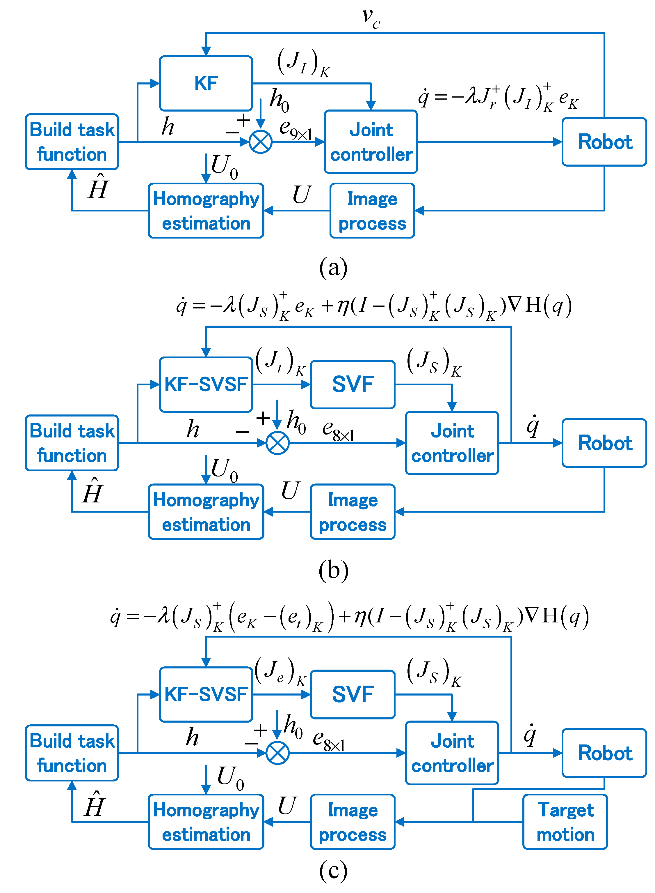
In this section, our improved strategy as shown in
Figure 2c will be described in detail. The first part details the new task function and provides related proofs. Then, the more robust Kalman filter–smooth variable structure filter (KF-SVSF) method will be introduced to estimate the total Jacobian. Finally, the estimated total Jacobian, processed via SVF to reduce the disturbance caused by an unstable conditional number, is used to build a controller to control the manipulator joints directly for both static positioning and dynamic tracking while limiting the joint angle.
3.1. Improved Homography-Based Task Function
In the original PHUVS strategy proposed by Zeyu Gong [
23], the homography-based task function is defined as
where
is the
row of the estimated homography matrix. The error vector of the system is denoted by
where
is constructed by stacking the rows of the identity matrix
. The purpose of our strategy can be considered to be making the current camera frame
coincide with
. To guarantee this, the constraint
is defined to obtain the unique projective homography matrix
between the current and desired feature points in each iteration. It can be proved that
if and only if rotation matrix
and position vector
[
23].
In our strategy, the constraint is defined, where is the last element of the homography matrix and a direct linear transformation (DLT) is introduced to estimate the homography matrix. First, it is necessary to normalize the two images, respectively, as follows:
Translate the feature points as and to ensure that the centroid of these feature points is at the origin;
Scale feature points as and to make their average distance from the origin equal to .
On the basis of the properties of homogeneous coordinates, homogeneous simultaneous equations can be constructed with transformed pixel coordinates as
where
is the coefficient matrix and
is the
ith row of
. The purpose of the above normalization operation is to prevent the coefficient matrix
from becoming ill-conditioned owing to image noise. This solves the problem of numerical instability.
Then, the least squares solution of equation (11) can be calculated via singular value decomposition. Then, we conduct an inverse transform on
as
where
is the estimated homography between the current and desired feature points. The homography
can be scaled at any scale.
Thus,
is scaled as
and the new task function is constructed as
where
reflects the eight degrees of freedom of the homography matrix and further reduces the dimensions of the system. The error vector of system is defined as
where
if and only if the rotation matrix
and the position vector
. Its sufficiency and necessity can be proved as follows.
Necessity proof: If and , then . On the basis of the similarity of and , we obtain . From Equation (8), we obtain . The constraint gives ; i.e., , , and .
Sufficiency: It is obvious that
and
if
. From Equation (7), we have
Taking two feature points, the coordinates of these points in
and
can be described as
Obviously, regardless of in which frame this is expressed, the distance between
and
is constant. That is,
This means that , which implies and . Thus, and .
This new task function takes full advantage of the property that the homography matrix has eight degrees of freedom. This not only reduces the dimensions of the task function but also simplifies the state space of the visual servo system that needs to be estimated online, so the real-time performance of system is further improved. Meanwhile, this causes the total Jacobian , which maps the task function and joint space of the hyper-redundant manipulator, to become redundant. Therefore, this redundancy can be used to finish some secondary tasks such as limiting the joint angle without a manipulator kinematic model during the servo process. Obviously, this improves the robustness of system to changes in the kinematic parameters of manipulators.
Remark 1. A flaw in the inhomogeneous solution of the homography matrix is that if the true value ofis 0 or very close to 0, the estimated homography matrix becomes very unstable. In fact, this situation rarely occurs in the visual servo. In static positioning tasks, the task function generally changes near to the desired gradient direction. As long asis not equal to 0 at the initial position, its value will never become 0 during the servo process. In tracking tasks, the task function is always close to the desired value.
3.2. Online Estimation of Total Jacobian
The kinematic parameters of the space manipulator change easily in the harsh space environment. To avoid the repeated calibration of the complex hyper-redundant manipulator, the total Jacobian between the task function and the joints of the manipulator is used to construct the controller. The expression of the total Jacobian is
Therefore, the accuracy of the estimation of the total Jacobian is directly related to the system performance.
The uncalibrated visual servo system of the nine degree-of-freedom (9 DOF) manipulator is modeled as
where
and
is the
row of the estimated total Jacobian
.
is constructed by the joint velocity of the manipulator, and
can be considered as the change rate of task function
.
It is worth noting that this model is a linear approximation of the visual servo system, and it causes modeling uncertainty. Meanwhile, because the homography-based task function is used to compensate for the image noise, the statistical characteristics of the measurement noise of the task function become difficult to obtain as well. Therefore, the more robust KF-SVSF method [
46,
47,
48] is introduced into the visual servo to improve the system accuracy.
This method combines the optimality of the KF method with the robustness of the SVSF method. As shown in
Figure 3, it introduces the concept of an optimal smoothing variable boundary layer, which is an estimation of the impact of modeling uncertainty and noise. The KF-SVSF method seeks a balance between accuracy and robustness by introducing a saturation limit into the calculated optimal boundary layer. By switching between KF gain and SVSF gain, the optimality of KF is maintained within the limit, while the robustness and stability of SVSF remain outside the limited range.
First, the smooth variable boundary layer can be obtained as follows:
Then, we complete the subsequent total Jacobian estimation process:
6. Calculate the a posteriori state error covariance matrix:
7. Obtain the estimated state vector
:
8. Split the state vector
into the estimated Jacobian
as:
Remark 2. When carrying out dynamic tracking tasks, the expanded total Jacobian matrixis estimated online, whererepresents the Jacobian between the gradient of the task function and the velocity of the target and is important for the construction of a dynamic tracking controller.
3.3. Controller Design
Several advanced controllers based on the estimated Jacobian can be used to realize a well-behaved uncalibrated visual servo; for example, a nonlinear controller with a disturbance observer and a disturbance-rejection controller with an extended-state observer [
25]. However, the proportional controller is still the most widely used and developed method in visual servos [
22,
23,
26,
29,
31,
32,
33,
34,
35,
36,
37,
38]. In addition, its simplicity is beneficial for us to verify this robust strategy.
Before constructing the proportional controller, two problems need to be solved. The first is the disturbance caused by the unstable conditional number of the estimated total Jacobian. Through a large number of simulations, it is found that the estimated Jacobian of the homography-based task function tends to present an unstable conditional number and causes drastic changes of the manipulator velocity in certain directions, resulting in severe vibrations and serious errors. Therefore, the SVF method is introduced to deal with this problem [
45]. Singular value decomposition is performed on the estimated total Jacobian
of the hyper-redundant manipulator according to
where
is the singular value of the total Jacobian
and
and
are the
columns of
and
, respectively. The filtering function
of the singular value
proposed in the SVF method can maintain the stability of the smallest singular value of the estimated total Jacobian. It is defined as
where
is the minimum acceptable singular value and
is a scaling factor that regulates the filtering shape of function
. If
and
,
can stay monotonic. The pseudo-inverse of the total Jacobian
can be developed via the SVF method as
The restriction on the minimum singular value guarantees the stability of the conditional number of the estimated total Jacobian. Thus, the disturbance caused by the unstable conditional number can be reduced without generating much additional error in the algorithms.
Another problem is that the manipulator joint angles may overrun. If the joint angle is not limited, it may cause a failure of the visual servo or even cause damage to the space manipulator. At this time, the redundancy of the joint space of the hyper-redundant manipulator resulting from the improved homography-based task function can be used to prevent this from happening. The gradient projection based on the redundant Jacobian can be adopted to avoid the joint limit [
41,
42]. When the joints move away from the limit of joint, allowing the joints to move freely can reduce unnecessary energy consumption. The gradient function is defined as
On the basis of these optimizations, the controllers for static positioning and dynamic tracking are designed, respectively, as follows:
Static positioning controller:
where
is the processed total Jacobian in the
period and
is the proportional gain.
Dynamic tracking controller:
where
is the estimation of the task function variation in the
period caused by target movement.


