Abstract
Four variants of elastic optical data center network (DCN) architectures based on optical circuit switching were proposed in an earlier study. The necessary and sufficient values of frequency slot units (FSUs) per fiber required for these four DCNs in the sense of there being strictly nonblocking (SNB) were derived, but no results in the sense of being rearrangeable nonblocking (RNB) were presented. In reality, only limited bandwidths are available, and reducing the value of FSUs per fiber has become a critical task to realize nonblocking optical DCN architectures in practice. In this paper, we derive the sufficient value of FSUs per fiber required for the four DCNs to be RNB by two multigraph approaches. Our results show that the proposed RNB conditions in terms of FSUs per fiber for a certain two of the four DCNs reduce their SNB results down to at least half for most cases, and even down to one-third.
1. Introduction
Recently, high transmission speed between the servers in data centers [1] has become an increasing requirement to meet the needs of current applications such as cloud computing and data mining. To support such high transmission speed, various data center network (DCN) architectures have been proposed [1,2,3,4]. One among them integrates an electronic packet switching (EPS) network and an optical circuit switching (OCS) network [1,2,4]. In such a hybrid electrical/optical architecture, both the EPS and OCS networks connect to each top-of-rack (ToR) switch simultaneously, where EPS serves small flows and OCS serves big flows. It has been shown that such a hybrid electrical/optical architecture reduces the power consumption and the operating expense [5,6].
An elastic optical network (EON) [7,8,9,10,11] is a candidate for being the OCS part of a DCN [2]. In EONs, flexible frequency grids proposed by ITU-T [12] are used, and a different number, say m, of adjacent frequency slot units (FSUs) are assigned to an optical connection, where m is usually upper bounded by a value, say mmax. The bandwidth of an FSU is 12.5 GHz [12], and a connection is called an m-slot connection if it is assigned m adjacent FSUs. Four variants of optical DCN architectures based on elastic optical switches, called DCN1, DCN2, DCN3 and DCN4, were proposed in [13]. The four DCN architectures are similar to wavelength-space-wavelength (W-S-W) networks [8,9,10], which are Clos-like architectures, but they do not adopt costly tunable wavelength converters as W-S-W networks do. In addition, the maximum number of connections generated from each input fiber in the four DCNs and W-S-W networks is limited due to the different components used. This leads to the nonblocking conditions derived for these four DCNs being different from those derived for W-S-W networks.
When a network is called nonblocking, it is in reference to the nonblocking traffic assigned to the network [14]. To prevent excessive blocking of connections, the network should be nonblocking. A network is called strictly nonblocking (SNB) if a connection will never be blocked by existing connections, and a network is called rearrangeable nonblocking (RNB) if a new connection can be accommodated by rearranging some existing connections [14]. An RNB network is also defined as one where any set (or frame) of connections can be routed simultaneously. The necessary and sufficient number of FSUs per fiber required for these four DCNs in the sense of their being SNB were given in [13], but no results in the sense of being RNB were proposed.
The four DCNs usually require a great number of FSUs per fiber to be SNB, especially when mmax is growing. However, the resource of FSUs per fiber in practical systems is limited since for the EON switches, and the C-band has only around 350 available FSUs (1530–1565 nm). Reducing the value of FSUs per fiber is a challenging task, and this issue has been studied in various research on EONs [8,9,10,11]. In order to reduce the value of FSUs per fiber to realize nonblocking optical DCN architectures in practice, we studied the four DCNs in the sense of being RNB in this paper, and derived the sufficient number of FSUs per fiber by adopting two multigraph approaches. Our results show that two of the proposed RNB conditions reduced the SNB results significantly.
The rest of the paper is organized as follows: In Section 2, we give a brief review of the four DCN architectures and introduce the notations used in the paper. In Section 3, we prove the RNB conditions for the DCN1 and DCN3 networks. In Section 4, we prove the RNB conditions for the DCN2 and DCN4 networks. Section 5 concludes the paper.
2. Preliminaries and Notations
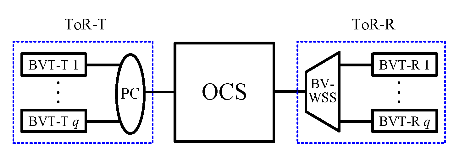
In this section, we will review the four elastic optical DCN architectures proposed in [13] and introduce the notations used in this paper. The four elastic optical DCN architectures require bandwidth-variable, waveband-selective switches (BV-WSSs) [15,16], bandwidth-variable space switches (BV-SSs), passive combiners (PCs) and ToR switches. Both BV-WSSs and BV-SSs, the latter of which consist of BV-WSSs and PCs, can switch wavebands with flexible bandwidths without spectrum conversion capabilities. Each ToR switch consists of q bandwidth-variable transponders (BVTs), which are divided into two parts: the transmission part, denoted by BVT-T, and the receiving part, denoted by BVT-R. The part of each ToR switch consisting of q BVT-Ts (or BVT-Rs) and a PC (or BV-WSS) is denoted by ToR-T (or ToR-R) (see Figure 1). A BVT-T can use any m consecutive FSUs of its output; i.e., the frequency of its output is arbitrarily tunable. In addition, a BVT-T is connected to a BVT-R in a strict one-to-one manner, and thus a BVT-T does not simultaneously send connections to two or more BVT-Rs. All connections generated from the same ToR switch occupy different FSUs, so that all of them can be sent through one fiber connecting the ToR-T (or ToR-R) to the OCS network.
Figure 1.
A ToR switch consisting of q BVTs.
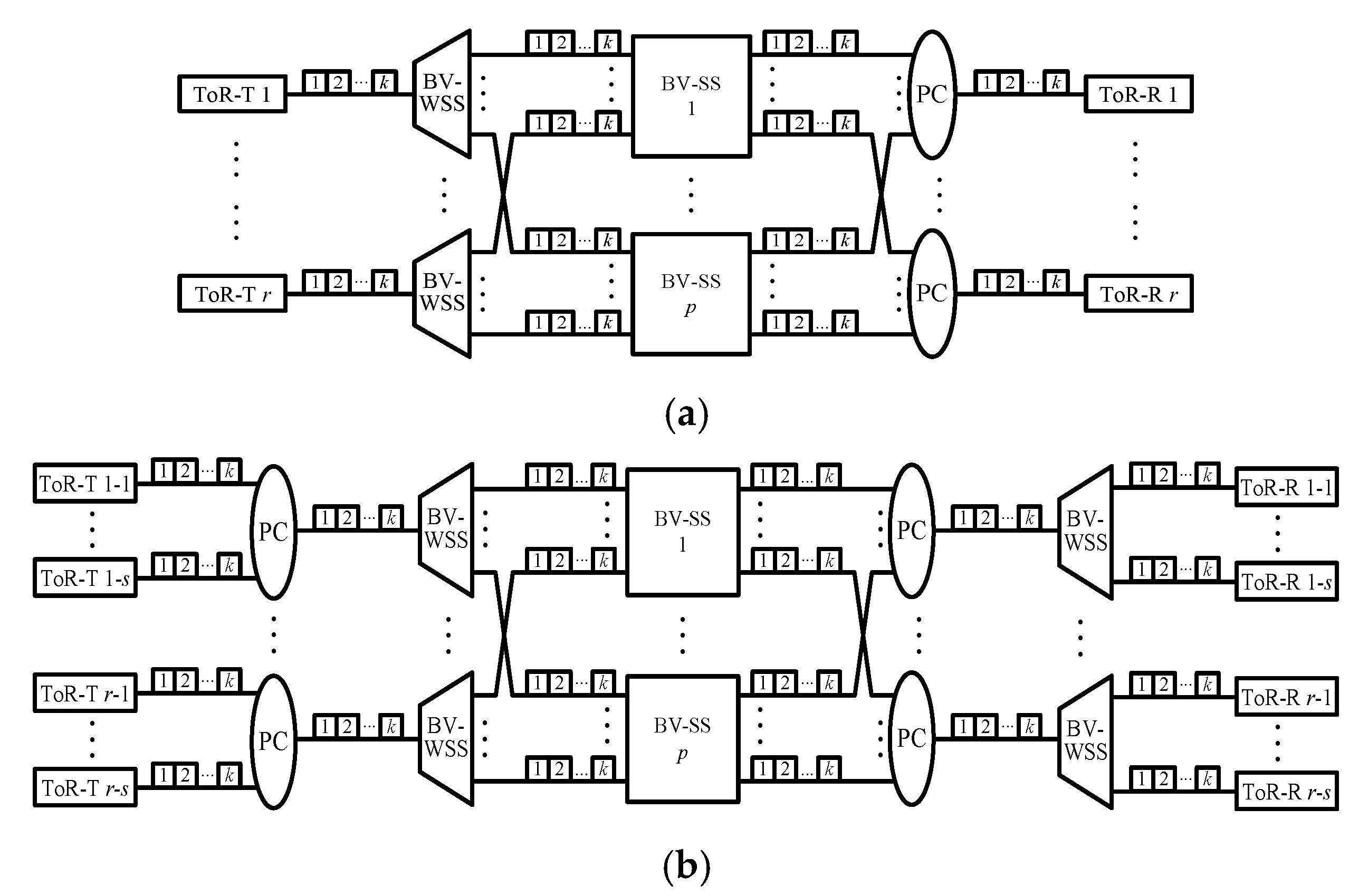
The DCN1 architecture, denoted by DCN1(r, q, k), is given in Figure 2a. A DCN1(r, q, k) network contains one r × r BV-SS and r ToR switches, each of which consists of q BVT-Ts (or BVT-Rs) and is attached to an input (or output) fiber with k FSUs of the BV-SS. The DCN2 architecture, denoted by DCN2(s, r, q, k), is a variant of DCN1(r, q, k) and is given in Figure 2b. A DCN2(s, r, q, k) network contains one r × r BV-SS and r groups of s ToR switches, which are combined by one PC into (or directed from one BV-WSS to) one input (or output) fiber connecting to the BV-SS. We use ToR-T (or ToR-R) u-i to denote the ith ToR-T (or ToR-R) in group u, where 1 ≤ u ≤ r and 1 ≤ i ≤ s. The DCN3 architecture is denoted by DCN3(r, q, k, p), and it contains p r × r BV-SSs and r ToR switches (Figure 3a). The output (or input) fiber of ToR-T u (or ToR-R v) is connected to one BV-WSS (or PC) which connects to the uth input (or vth output) of each BV-SS. Finally, the DCN4 architecture is denoted by DCN4(s, r, q, k, p), and it is obtained from a DCN2(s, r, q, k) network by adopting p BV-SSs to connect ToR-Ts and ToR-Rs (Figure 3b).

Figure 2.
(a) A DCN1(r, q, k) network and (b) a DCN2(s, r, q, k) network, where each ToR-T (or ToR-R) consists of q BVT-Ts (or BVT-Rs), as given in Figure 1.
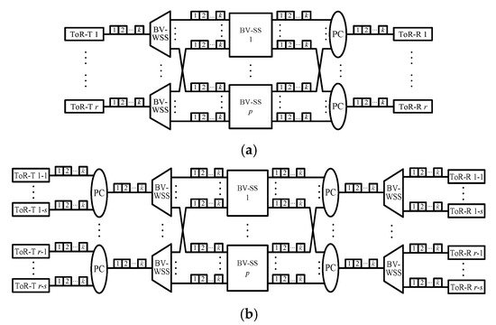
Figure 3.
(a) A DCN3(r, q, k, p) network, and (b) a DCN4(s, r, q, k, p) network, where each ToR-T (or ToR-R) consists of q BVT-Ts (or BVT-Rs), as given in Figure 1.
The four DCN architectures serve m-slot connections with m ≤ mmax. To guarantee that each fiber occupying k FSUs is sufficient to carry connections served by all BVT-Ts, the value of k is assumed to be k ≥ qmmax (or k ≥ sqmmax) for the DCN1 and DCN3 (or DCN2 and DCN4) architectures. An m-slot connection from a BVT-T in ToR-T u (or ToR-T u-i) to a BVT-R in ToR-R v (or ToR-R v-j) in a DCN1 or DCN3 (or a DCN2 or DCN4) is denoted by (u, v, m) (or (u-i, v-j, m)), where 1 ≤ u, v ≤ r and 1 ≤ i, j ≤ s.
FSUs in each fiber are numbered from 1 to k. To set up a connection (u, v, m) (or (u-i, v-j, m)), the same sets of m adjacent FSUs must be found in both the fiber connecting ToR-T u (or ToR-T u-i) with one BV-SS and the fiber connecting this BV-SS with ToR-R v (or ToR-R v-j). If those sets do not exist, the connection is blocked. The necessary and sufficient values of k for DCN1 to DCN4 in the sense of being SNB were given in [13]. We quote the SNB results for the DCN1 and DCN2 networks in Lemmas 1 and 2 for further comparison in Section 3 and Section 4.
Lemma 1.
A DCN1(r, q, k) network for m-slot connections with 1 ≤ m ≤ mmax is SNB if and only if
k ≥ kSNB = 2(q − 1)·(2mmax − 1) + mmax
Lemma 2.
A DCN2(s, r, q, k) network for m-slot connections with 1 ≤ m ≤ mmax is SNB if and only if
k ≥ k′SNB = 2(sq − 1)·(2mmax − 1) + mmax
3. RNB DCN1 and DCN3 Networks
In this section, we first consider the RNB DCN1 network and then the RNB DCN3 network. In order to derive the sufficient value of k for a DCN1(r, q, k) network in the sense of being RNB, we propose a multigraph approach and a routing algorithm in the following.
3.1. Multigraph Approach and Routing Algorithm
Given a DCN1(r, q, k) network and a frame F of connections, we propose Multigraph Approach A, given below, to convert the DCN1(r, q, k) network for frame F into a multigraph GF.
Multigraph Approach A:
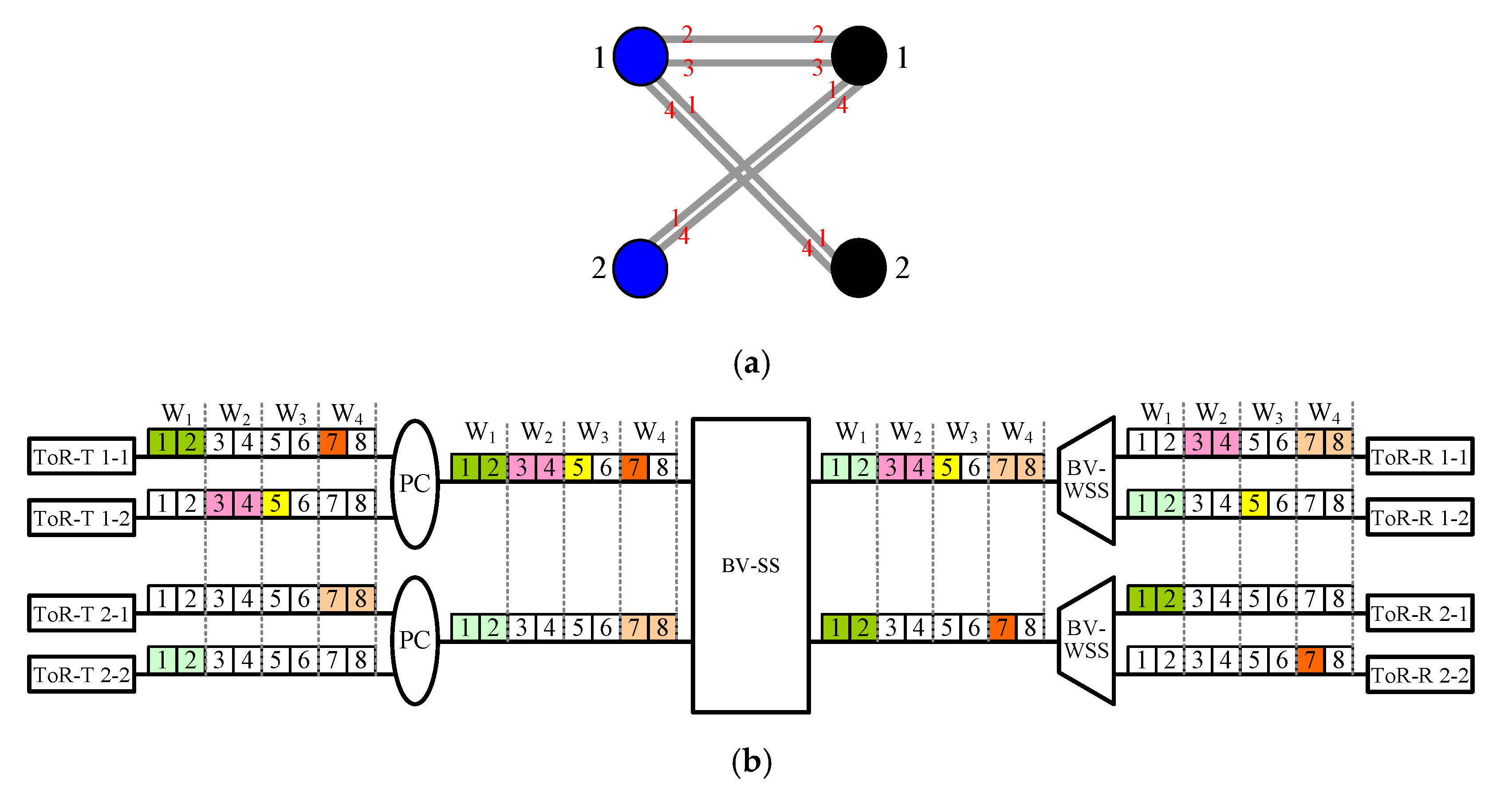
Let each left vertex u (or right vertex v) in multigraph GF be ToR-T u (or ToR-R v) of the DCN1(r, q, k) network. In multigraph GF, there is an edge connecting vertexes u and v if there is an m-slot connection from a BVT-T in ToR-T u and it is destined to a BVT-R in ToR-R v, i.e., (u, v, m) (see Figure 4a). Note that we call GF a multigraph [17] because multiple connections between ToR-T u and ToR-R v are allowed, and thus there could be more than one edge connecting vertexes u and v in GF.

Figure 4.
Given a DCN1(4, 3, 9) network and a frame F of connections (1, 1, 3), (1, 2, 3), (1, 3, 2), (2, 2, 2), (2, 4, 3), (3, 1, 1), (4, 3, 2) and (4, 4, 2): (a) The corresponding multigraph GF constructed by Multigraph Approach A. Note that GF is edge-colored by colors 1, 2, and 3 (marked in red), and left and right vertices are marked in blue and black, respectively. (b) A routing of connections in frame F according to Routing Algorithm A in association with the edge-coloring of GF.
In Property 1, we show that GF is q-edge-colorable.
Property 1.
Given a DCN1(r, q, k) network and a frame F of connections, let GF be the corresponding multigraph constructed by Multigraph Approach A. Multigraph GF is q-edge-colorable.
Proof.
Let Δ(GF) be the maximum degree of GF. Since each ToR switch consists of q BVT-Ts and q BVT-Rs, at most q m-slot connections can be generated from a ToR-T (or destined to a ToR-R). Thus, we have Δ(GF) ≤ q. From the construction of GF, we can see that GF is a bipartite multigraph. In addition, GF is q-edge-colorable according to graph theory [17] if GF is a bipartite multigraph with Δ(GF) ≤ q. □
In a DCN1(r, q, k) network, we use Iu (or Ov) to denote the fiber connecting ToR-T u (or ToR-R v) and the BV-SS, where k ≥ qmmax and 1 ≤ u, v ≤ r. In addition, we partition each fiber with k FSUs into q parts, each of which consists of mmax consecutive FSUs. Each part is called a window, and these q windows, denoted by Wl for 1 ≤ l ≤ q, are numbered from 1 from left to right. We use |Wl| to represent the size of window Wl, and also use Iu,l (or Ov,l) to represent the lth window in fiber Iu (or Ov) for 1 ≤ u, v ≤ r and 1 ≤ l ≤ q.
Recall that GF is q-edge-colorable (Property 1). Let colors 1, 2,…, q be adopted to edge color GF. We route each (u, v, m) for the RNB condition [14] using Routing Algorithm A given below.
Routing Algorithm A:
Connection (u, v, m) is routed in windows Iu,c and Ov,c if color c is assigned to the corresponding edge of (u, v, m) in GF (see Figure 4b).
3.2. RNB Sufficient Conditions
A sufficient value of k for a DCN1(r, q, k) network in the sense of being RNB is derived in Property 2.
Property 2.
A DCN1(r, q, k) network for m-slot connections with 1 ≤ m ≤ mmax is RNB if
k ≥ kRNB = q·mmax
Proof.
This property holds if Routing Algorithm A is feasible, and Routing Algorithm A is feasible if each m-slot connection can be carried by the corresponding windows. Since m ≤ mmax, each m-slot connection can be carried by any window Wl if |Wl| = mmax for 1 ≤ l ≤ q, which implies that each fiber has k = q·mmax FSUs. Therefore, when Routing Algorithm A is applied, a DCN1(r, q, k) network with k ≥ q·mmax is RNB. □
Comparing Equation (3) with Equation (1), we have kRNB/kSNB ≤ 1/2 for mmax ≥ 2 and q ≥ 3. Property 2 implies that kRNB reduces the SNB DCN1 result given in [13], namely, kSNB, down to at least half for most cases. In addition, numerical results are given in Table 1 which show that kRNB can reduce kSNB down to as low as one third, for example, the cases with mmax ≥ 6 and q = 4, and the cases with mmax ≥ 4 and q ≥ 8.

Table 1.
Numerical results of k required for being an SNB or RNB DCN1(r, q, k) network for m-slot connections with q = 4, 8, 10 and 1 ≤ m ≤ mmax, where kSNB and kRNB are given in Equations (1) and (3), respectively.
The sufficient condition for being an RNB DCN1(r, q, k) network (Property 2) is also the necessary condition if only one connection rate mmax is considered (Property 3).
Property 3.
Suppose only one connection rate, mmax, is considered. Then, the DCN1(r, q, k) network is RNB if and only if k ≥ kRNB = q·mmax.
Proof.
The sufficient condition of this property is true since it is a special case with one connection rate of Property 2. In addition, the necessary condition holds when q connections (u, u, mmax) for 1 ≤ u ≤ r are generated from each ToR-T u. □
From the architectures of the DCN1 and DCN3 networks (see Figure 2a and Figure 3a), we can see that a DCN1(r, q, k) network for k ≥ q·mmax functions the same as a DCN3(r, q, k, p) network with p = 1. Thus, we derive Property 4 immediately.
Property 4.
A DCN3(r, q, k, p) network for m-slot connections with 1 ≤ m ≤ mmax and k ≥ q·mmax is RNB if p ≥ 1.
Proof.
This property is true for two reasons: i) a DCN3(r, q, k, p) network with p = 1 functions as well as a DCN1(r, q, k) network, and ii) a DCN1(r, q, k) network for k ≥ q·mmax is RNB (Property 2). □
For a DCN1(r, q, k) (or DCN3(r, q, k, p)) network, recall that the resource of FSUs per fiber in practical systems is limited, namely, k ≤ 350. This implies that to have an RNB DCN1(r, q, k) (or DCN3(r, q, k, p)) network for m-slot connections with 1 ≤ m ≤ mmax in the real word, we also need q·mmax ≤ 350 due to Property 2 (or Property 4).
4. RNB DCN2 and DCN4 Networks
Similar to Section 3, we first consider the RNB DCN2 network and then the RNB DCN4 network. For the DCN2 network (Figure 2b), Iu-i (or Ov-j) is used to represent the fiber connecting ToR-T u-i (or ToR-R v-j) and the uth PC (or vth BV-WSS), and I’u (or O’v) is used to represent the fiber connecting the uth PC (or vth BV-WSS) and the BV-SS for 1 ≤ u, v ≤ r and 1 ≤ i, j ≤ s. Next, we will propose Multigraph Approach B and Routing Algorithm B for the DCN2 network in the sense of being RNB by modifying Multigraph Approach A and Routing Algorithm A, respectively.
Multigraph Approach B:
Given a DCN2(s, r, q, k) network and a frame F of connections, multigraph G’F is constructed in the following way. Let each left vertex u (or right vertex v) in G’F be the uth (or vth) group of s ToR-Ts u-i (or ToR-Rs v-j) for 1 ≤ i, j ≤ s. An edge is added between two vertexes u and v in G’F if there is an m-slot connection from the uth ToR-T group destined to the vth ToR-R group (see Figure 5a).
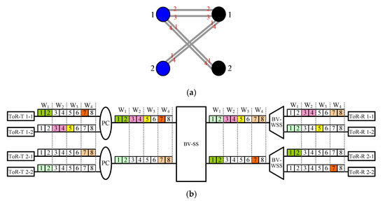
Figure 5.
Given a DCN2(2, 2, 2, 8) network and a frame F of connections (1-1, 2-1, 2), (1-1, 2-2, 1), (1-2, 1-1, 2), (1-2, 1-2, 1), (2-1, 1-1, 2) and (2-2, 1-2, 2): (a) The corresponding multigraph G’F generated by Multigraph Approach B. Note that G’F is edge-colored by colors 1, 2, 3 and 4 (marked in red font), and left and right vertices are marked in blue and black, respectively. (b) A routing of connections in frame F according to Routing Algorithm B in association with the edge-coloring of G’F.
Since each group of ToR switches can generate at most sq m-slot connections, we derive that Δ(G’F) ≤ sq, and thus G’F is sq-edge-colorable [17]. Let colors 1, 2,…, sq be used to edge-color G’F. We adopt Routing Algorithm B, shown below, to route each (u-i, v-j, m) in association with the edge-coloring of G’F for the RNB condition.
Routing Algorithm B:
Connection (u-i, v-j, m) is routed in windows Iu-i,c, I’u,c, O’v,c and Ov-j,c if color c is assigned to the corresponding edge of (u-i, v-j, m) in G’F (see Figure 5b).
Similar to Properties 2–4, we have Properties 5–7, as follows.
Property 5.
A DCN2(s, r, q, k) network for m-slot connections with 1 ≤ m ≤ mmax is RNB if
k ≥ k’RNB = sq·mmax
Proof.
The proof is similar to that of Property 2. □
Property 6.
Suppose only one connection rate, mmax, is considered. Then a DCN2(s, r, q, k) network is RNB if and only if k ≥ k’RNB = sq·mmax.
Proof.
The proof is similar to that of Property 3. □
Property 7.
A DCN4(s, r, q, k, p) network for m-slot connections with 1 ≤ m ≤ mmax and k ≥ sq·mmax is RNB if p ≥ 1.
Proof.
From the topology of the DCN4 architecture (see Figure 3b), we can see that a DCN4(s, r, q, k, p) network with p = 1 and k ≥ sq·mmax functions as well as a DCN2(s, r, q, k) network. According to Property 5, the property holds immediately. □
Comparing Equation (2) with Equation (4), we have k’RNB/k′SNB ≤ 1/2 for mmax ≥ 2 and sq ≥ 3. Property 5 implies that k’RNB reduces the SNB DCN2 result given in [13], namely, k’SNB, down to at least half for most cases, and even down to one third. In addition, numerical results are given in Table 2, which shows that k′RNB can reduce k′SNB down to as low as one third, for example, all the cases with mmax ≥ 4, s = 3 and q ≥ 4. Again, due to the limited resource of FSUs per fiber in practical systems, to have an RNB DCN2(s, r, q, k) (or DCN4(s, r, q, k, p)) network for m-slot connections with 1 ≤ m ≤ mmax in the real word, we need sq·mmax ≤ 350 due to Property 5 (or Property 7).

Table 2.
Numerical results of k required for being an SNB or RNB DCN2(s, r, q, k) network for m-slot connections with s = 3, q = 4, 8, 10 and 1 ≤ m ≤ mmax, where k’SNB and k’RNB are given in Equations (2) and (4), respectively.
5. Conclusions
Four variants of elastic optical DCN architectures, called DCN1, DCN2, DCN3 and DCN4, were proposed in [13]. The four DCNs in the sense of being SNB usually require a large number of FSUs per fiber. To reduce the value of FSUs, we considered the four DCNs in the sense of their being RNB in this paper. We proposed two multigraph approaches to firstly prove the sufficient number of FSUs per fiber for these four DCNs in the sense of there being RNB. Our results show that the proposed RNB conditions in term of FSUs per fiber for the DCN1 and DCN2 networks reduce their SNB results down to at least half in most scenarios, and even down to one third. In addition, we show that the sufficient condition for an RNB DCN3 (or DCN 4) network is exactly the same as that derived for an RNB DCN1 (or DCN 2) network. The proposed multigraph approaches can be applied to all Clos-like architectures for studying RNB conditions.
Funding
This work was supported by the Ministry of Science and Technology, Taiwan, under Contract MOST 108-2221-E-024-002-MY2.
Conflicts of Interest
The authors declare no conflict of interest.
References
- Kachris, C.; Tomkos, I. A survey on optical interconnects for data centers. IEEE Commun. Surv. Tutor. 2012, 14, 1021–1036. [Google Scholar] [CrossRef]
- Yoo, S.J.B. Integrated photonic-electronic technologies for next generation data centers and the future internet. In Proceedings of the 2012 International Conference on Photonics in Switching (PS), Ajaccio, France, 11–14 September 2012. [Google Scholar]
- Fiorani, M.; Aleksic, S.; Casoni, M. Hybrid optical switching for data center networks. J. Electr. Comput. Eng. 2014, 2014, 1–13. [Google Scholar] [CrossRef]
- Hamza, A.S.; Deogun, J.S.; Alexander, D.R. Wireless communication in data centers: A survey. IEEE Commun. Surv. Tutor. 2016, 18, 1572–1595. [Google Scholar] [CrossRef]
- Ji, P.N.; Kachris, C.; Tomkos, I.; Wang, T. Energy efficient data center network based on a flexible bandwidth MIMO OFDM optical interconnect. In Proceedings of the 4th IEEE International Conference on Cloud Computing Technology and Science Proceedings, Taipei, Taiwan, 3–6 December 2012. [Google Scholar]
- Kachris, C.; Ji, P.N.; Wang, T.; Tomkos, I. Energy efficient flexible bandwidth OFDM-based data center network. In Proceedings of the 2012 IEEE 1st International Conference on Cloud Networking (CLOUDNET), Paris, France, 28–30 November 2012. [Google Scholar]
- Lopez, V.; Velasco, L. Elastic Optical Networks: Architectures, Technologies, and Control; Springer International Publishing: Cham, Switzerland, 2016. [Google Scholar]
- Kabaciński, W.; AI-Tameemi, A.; Rajewski, R. Necessary and sufficient conditions for the rearrangeability of WSW1 switching fabrics. IEEE Access 2019, 7, 18622–18633. [Google Scholar] [CrossRef]
- Lin, B.-C. Rearrangeable W-S-W elastic optical networks generated by graph approaches. IEEE OSA J. Opt. Commun. Netw. 2018, 10, 675–685. [Google Scholar] [CrossRef]
- Kabaciński, W.; Abdulsahib, M. Wide-sense nonblocking converting-space-converting switching node architecture under XsVarSWITCH control algorithm. IEEE ACM Trans. Netw. 2020, 28, 1550–1561. [Google Scholar] [CrossRef]
- Danilewicz, G. Asymmetrical space-conversion-space SCS1 strict-sense and wide-sense nonblocking switching fabrics for continuous multislot connections. IEEE Access 2019, 7, 107058–107072. [Google Scholar] [CrossRef]
- Spectral Grids for WDM Applications: DWDM Frequency Grid. In ITU-T Standard G.694.1; International Telecommunications Union (CCIR) and (CCITT): Geneva, Switzerland, 2012.
- Kabaciński, W.; Michalski, M.; Rajewski, R.; Żal, M. Optical datacenter networks with elastic optical switches. In Proceedings of the 2017 IEEE International Conference on Communications, Paris, France, 21–25 May 2017. [Google Scholar]
- Hwang, F. The Mathematical Theory of Nonblocking Switching Networks; World Scientific: Singapore, 2004. [Google Scholar]
- 1×9/1×20 Flexgrid® Wavelength Selective Switch (WSS). 2015. Available online: https://www.finisar.com/sites/default/files/downloads/1×9_1×20_flexgrid_wss_pb_v3.pdf (accessed on 18 September 2020).
- Xie, D.; Wang, D.; Zhang, M.; Liu, Z.; You, Q.; Yang, Q.; Yu, S. LCoS-based wavelength-selective switch for future finer-grid elastic optical networks capable of all-optical wavelength conversion. IEEE Photon. J. 2017, 9, 7101212. [Google Scholar] [CrossRef]
- West, D.B. Introduction to Graph Theory; Pearson: London, UK, 2001. [Google Scholar]
Publisher’s Note: MDPI stays neutral with regard to jurisdictional claims in published maps and institutional affiliations. |
© 2020 by the author. Licensee MDPI, Basel, Switzerland. This article is an open access article distributed under the terms and conditions of the Creative Commons Attribution (CC BY) license (http://creativecommons.org/licenses/by/4.0/).

