Article

Photonic Microwave Distance Interferometry Using a Mode-Locked Laser with Systematic Error Correction

1
Department of Mechanical Engineering, Korea Advanced Institute of Science and Technology (KAIST), 291 Daehak-ro, Yuseong-gu, Daejeon 34141, Korea
2
Ultra-Precision Optoelectronic Instrument Engineering Center, Harbin Institute of Technology, School of Electrical Engineering and Automation, Harbin 150001, China
3
NanoSystem Co. Ltd., 90 Techno 2-ro, Yuseong-gu, Daejeon 34014, Korea
4
Department of Ultra-Precision Machines and Systems, Korea Institute of Machinery & Materials (KIMM), Daejeon 34103, Korea
5
Length Standard Group, Physical Metrology Division, Korea Research Institute of Standards and Science (KRISS), 267 Gajeong-ro, Yuseong-gu, Daejeon 34113, Korea
*
Authors to whom correspondence should be addressed.
Appl. Sci. 2020, 10(21), 7649; https://doi.org/10.3390/app10217649
Submission received: 29 September 2020 / Revised: 28 October 2020 / Accepted: 28 October 2020 / Published: 29 October 2020
(This article belongs to the Special Issue Manufacturing Metrology)

Abstract

:
We report an absolute interferometer configured with a 1 GHz microwave source photonically synthesized from a fiber mode-locked laser of a 100 MHz pulse repetition rate. Special attention is paid to the identification of the repeatable systematic error with its subsequent suppression by means of passive compensation as well as active correction. Experimental results show that passive compensation permits the measurement error to be less than 7.8 μm (1 σ) over a 2 m range, which further reduces to 3.5 μm (1 σ) by active correction as it is limited ultimately by the phase-resolving power of the phasemeter employed in this study. With precise absolute distance ranging capability, the proposed scheme of the photonic microwave interferometer is expected to replace conventional incremental-type interferometers in diverse long-distance measurement applications, particularly for large machine axis control, precision geodetic surveying and inter-satellite ranging in space.

1. Introduction

Distance interferometry employing lasers has long been used for precision ranging and positioning in diverse industrial applications [1,2]. Continuous-wave monochromatic sources such as He–Ne gas lasers or semiconductor diode lasers are preferably used to attain sub-wavelength resolutions by performing phase-measuring interferometry based on homodyne or heterodyne principles [3,4]. Such continuous-wave laser interferometry basically leads to incremental displacement measurement, whereas absolute positioning interferometry requires incorporating additional source functionality such as intensity modulation [5], frequency sweeping [6], and multiple wavelengths [7]. In general, most industrial applications favor absolute positioning interferometry, but its measurement accuracy when attained with continuous-wave lasers is limited by the practical difficulties encountered in extending the source functionalities. As a result, incremental displacement interferometry using continuous-wave lasers is still widely used, with absolute positioning being achieved by the digital accumulation of instantaneous distance increments. At the same time, the zero-datum of absolute positioning has to be set up arbitrary by installing a fiducial reference in advance.
With the aim of providing a new light source for absolute positioning interferometry, mode-locked pulse lasers are being investigated to provide more efficient functionalities beyond continuous-wave lasers [8,9,10]. As a result, by making the most of the unique spectral and temporal characteristics of mode-locked lasers, various novel methods for absolute positioning have so far been demonstrated; they are conveniently referred to as synthetic wavelength interferometry [11,12], spectral-resolved interferometry [13,14], dual-comb interferometry [15,16], optical cross-correlation [17,18] and multi-wavelength interferometry [19,20]. Each method has its own capability of utilizing mode-locked lasers as an alternative source for absolute positioning, and particularly the method of synthetic wavelength interferometry draws attention as it utilizes microwaves that are photonically synthesized directly from the pulse repetition rate of a mode-locked laser. Compared with conventional microwaves that are electrically generated by means of intensity or frequency modulation, the photonic microwaves offer superior stability in frequency and intensity so as to implement long-distance ranging with high precision. Accordingly, efforts are being made to apply photonic microwaves to large-scale industrial metrology [21] and space missions such as multiple satellite formation flying [22,23].
In this investigation, we describe a 1 GHz microwave distance interferometer based on the 10th inter-mode harmonic of a 100 MHz pulse repetition rate of a fiber mode-locked laser. A comprehensive analysis is made for correction of the systematic error through pre-calibration with respect to a commercial incremental He–Ne laser interferometer. The photonic microwave created in this study is able to offer an accurate length ruler with a 0.3 m wavelength stabilized to the Rb clock, with a fractional instability of 10−11 at 1 s averaging. The repeatable systematic measurement error attributable to the optical and radio frequency (RF) electrical disturbance embedded in the interferometer system is identified and corrected by passive and active suppression schemes. Experimental results reveal that absolute positioning can be achieved within a residual error of 3.5 μm (1 σ) over a 2.0 m distance, which corresponds to a phase resolution of ~0.0084°, which is in fact comparable to the phase resolving power of the phasemeter configured in this study using a lock-in amplifier.

2. Photonic Microwave Distance Interferometer

2.1. Interferometer Configuration

Figure 1 describes the distance interferometer devised in this investigation. The light source is an Er-doped fiber mode-locked laser emitting 120 fs short pulses at a repetition rate (fr) of 100 MHz. When the laser pulses are observed using a photodetector over a time period, the resulting electrical signal exhibits an RF comb structure in the frequency domain. As illustrated in Figure 1a, the resulting RF comb is in fact a down-converted version of the optical comb of the mode-locked source. Each RF comb mode element represents an integer-multiple harmonic frequency of the pulse repetition rate fr, which can be isolated from other modes through an electrical bandpass filter. An N-th harmonic frequency has the wavelength (ΛN), expressed as Λ N = c N f r , with c being the speed of light in a vacuum. Lower harmonic frequencies, i.e., longer wavelengths, are preferable as the interferometer source to enlarge the non-ambiguity range of distance measurement, whereas higher harmonic frequencies offer finer measurement resolutions.
The source beam is launched into free space and divided into the reference beam (green) and measurement beam (blue) with a 50:50 beam splitter as shown in Figure 1b. Both the reference beam and measurement beam are converted into electrical signals and mixed with a local oscillator signal (1 GHz–100 kHz) stabilized to the Rb atomic clock by phase-locked loop (PLL) control as shown in Figure 1c. The reference beam directly goes to a reference photodetector, while the measurement beam reaches a measurement photodetector after reflecting from a target mirror installed on a motorized stage with a 2.5 m travel range. In this study, the 10th harmonic of 1 GHz is selected to be used as the microwave source. The phase delay (θN) of the 1 GHz source microwave signal is measured by down-shifting to a 100 kHz signal using an electrical local oscillator set to operate near 1 GHz. The target distance (L) is then determined as:
L = Λ N 2 n air ( m N + θ N )
where nair denotes the refractive index of air and mN is an integer. The phase delay θN between the measurement and measurement paths is measured with respect to the particular photonic wavelength ΛN. Finally, the super-heterodyned electrical signals of 100 kHz are processed through a lock-in amplifier that is used as a phase meter to determine the interferometric phase delay θN. The phase measurement resolution is found to be 0.01° with an accuracy of 0.02°, from which the measurement precision is estimated to be 4.2 μm.

2.2. Measurement Repeatability

The measurement repeatability was evaluated at a fixed target distance of about 1 m. Figure 2a shows a typical time-trace of distance measurement with an update rate of 10 Hz (blue) and 0.1 Hz (yellow), respectively. Over a time period of 1000 s, the measured distance fluctuates within a few tens of micrometers as clearly seen in the measurement histogram, appearing to be a Gaussian shape. For quantitative evaluation of the measurement repeatability, the Allan deviation of the time-trace measurement was calculated as shown in Figure 2b, from which the measurement repeatability is estimated to be 9.5 and 2.5 μm at an averaging of 0.1 s and 10 s, respectively. It is important to note that the best measurement repeatability achievable near 10 s averaging is practically limited by the detection resolution of the used phasemeter of lock-in amplifier type, not by the photonic microwave signal stability of the mode-locked laser source.

3. Systematic Error Correction

3.1. Systematic Error Analysis

We performed distance measurements repeatedly over a range of 0.5 to 2.5 m back and forth with 10 mm steps as illustrated in Figure 3. Each position value is represented by an average of 60 consecutive measurements taken over a period of 6 s. The averaged distance was compared with its counterpart value obtained simultaneously with a commercial incremental-type He–Ne laser interferometer, of which the discrepancy was plotted in Figure 3a. At each distance, with respect to the He–Ne laser interferometry, the measurement error of our interferometer was evaluated by processing eight individual data sets. The measurement error appears to be a sum of two separable terms; one is the non-repeatable random error and the other is the repeatable systematic error. In principle, the random error determines the measurement precision ultimately achievable, whereas the systematic error can be eliminated through correction at each position. Further, as depicted in Figure 3b, it is also important to note that the repeatability of the systematic error can be either periodic (orange line) or non-periodic (purple line).
In general, it is known that the periodic systematic error is caused by the signal leakage occurring in the interferometer optics or electronics, with the period appearing to be identical to the wavelength of the microwave signal used in distance measurement [24]. On the other hand, the non-periodic systematic error arises from the amplitude-to-phase error conversion due to the light intensity fluctuation as well as the imperfect RF electronics of nonlinear behaviors [25,26]. For the 1 GHz microwave wavelength employed in this study, the periodic error is found to have an amplitude of 22.6 μm with an actual period of 0.15 m. The periodic error is attributable to the cyclic cross talk of the measurement signal with unwanted signals. Yielding no position-dependency, the periodic error is generated by the RF circuit noise, as well as the partially-reflected laser beam from the interferometer optics for beam splitting and recombination. The effect of cross talk on the measurement error can be modelled as [24]:
cos ( 2 π f c 2 L ) + ε crosstalk cos ( θ crosstalk ) = cos ( 2 π f c 2 L + θ p eriodic   error ( L ) )
where f is the carrier frequency (here 1 GHz), c is the speed of light, L is the target distance, εcrosstalk is the cross talk ratio to the measurement signal, θcrosstalk is the constant phase of the cross talk components and θperiodic error (L) is the periodic error induced by cross talk as a function of the target distance L. In our case, the cross talk ratio εcrosstalk is found to be 0.1%, as illustrated in Figure 3c.
The non-periodic systematic error shown in Figure 3a is found to be ±300 μm, with a position dependency with a strong correlation with the optical power actually received by the photodetector, as shown in Figure 3d. This confirms that the non-periodic error is attributable to the amplitude-to-phase conversion caused by the photodiode and RF components. However, the microwave phase is not reciprocal for increasing and decreasing the direction of the received optical power.

3.2. Passive Correction by Post-Processing

Figure 4 shows the passive correction results of the systematic error, of which the mean line before correction is shown in Figure 3a. The residual error after correction is found to be ±7.8 μm (1 σ) over a 2 m range. The accuracy of the phasemeter used in the calibration is 0.02°, which corresponds to 8.4 μm. This implies that our passive correction almost reached the ultimate limitation imposed by the phasemeter. For more comprehensive analysis, the residual error after correction was Fourier transformed as shown in Figure 4b. The result revealed that the periodic error of an amplitude of 22.6 μm is completely suppressed, whereas the residual error after correction is mainly dominated by the non-periodic error.

3.3. Active Correction by Compensating Optical Power

Figure 5 shows the result of active correction of the systematic error. The optical power received by the interferometer photodetectors in the measurement and reference arms varies while the target is translated on the motorized stage. The optical power fluctuation is detected within the lock-in amplifier as illustrated Figure 5a, and stabilized by controlling the gain of the RF amplifier installed in the measurement arm circuit. As a consequence, the amplitude of the measurement signal into the lock-in amplifier is kept constant with a maximum deviation of 0.014% as depicted in Figure 5b. As discussed in the previous section, because the non-periodic error is dominantly influenced by the amplitude-to-phase conversion in RF components, the optical power stabilization is able to actively eliminate the non-periodic error. As a result, the systematic error is observed only in the form of cyclic error without the non-periodic error over a 2-m travel range, as shown in Figure 5c. The residual cyclic error can be corrected by post-processing so that the total measurement error remains within the level of ±3.5 μm (1 σ).

4. Conclusions

We have demonstrated a photonic scheme of an absolute distance interferometer using a 1 GHz microwave synthesized by the 10th harmonic of the pulse repetition rate of a fiber mode-locked laser. The photonic microwave offers an accurate length ruler with a 0.3 m wavelength stabilized to the Rb clock with a fractional instability of 10−11 at 1 s averaging. However, the measured interferometric phase is disturbed by optical and RF electrical components comprising the interferometer system, which were identified by measurements and subsequently corrected by passive and active schemes of systematic error suppression. Experimental results revealed that the systematic error can be corrected to a residual level of 7.8 μm in terms of the standard deviation (1 σ), which is a phase measurement error of ~0.0084°, comparable to the resolution of the lock-in amplifier used in phase measurement. It is expected that the measurement error can be enhanced to a sub-micron level by selecting a higher microwave frequency, along with high frequency RF components that will be available in the near future. It is also important to note that the scheme of photonic microwave interferometry can be a promising candidate for practical use of the frequency comb-based distance measurement with traceability to the time/frequency standard, which can be applied to high-precision machine axis control as well as long distance measurement space missions such as geodetic survey and inter-satellite ranging.

Author Contributions

Conceptualization, Y.-S.J. and S.-W.K.; methodology, W.K.; software, H.F.; validation, W.K., H.F. and Y.-S.J.; formal analysis, W.K.; investigation, H.F.; resources, K.L.; data curation, S.H.; writing—original draft preparation, Y.-S.J.; writing—review and editing, S.-W.K.; visualization, W.K.; supervision, Y.-S.J.; project administration, S.-W.K.; funding acquisition, S.-W.K. All authors have read and agreed to the published version of the manuscript.

Funding

This work was supported by the National Research Foundation of the Republic of Korea (NRF-2012R1A3A1050386).

Acknowledgments

Y.-S. Jang acknowledges support from the KRISS (20011030) and S. Han appreciates support from the KIMM (NK224A).

Conflicts of Interest

The authors declare no conflict of interest.

References

  1. Gao, W.; Kim, S.-W.; Bosse, H.; Haitjema, H.; Chen, Y.L.; Lu, X.D.; Knapp, W.; Weckenmann, A.; Estler, W.T.; Kunzmann, H. Measurement technologies for precision engineering. CIRP Ann. Manuf. Technol. 2015, 64, 773–796. [Google Scholar]
  2. Berkovic, G.; Shafir, E. Optical methods for distance and displacement measurements. Adv. Opt. Photon. 2012, 4, 441–473. [Google Scholar] [CrossRef]
  3. Bobroff, N. Recent advances in displacement measuring interferometry. Meas. Sci. Technol. 1993, 4, 907–926. [Google Scholar] [CrossRef]
  4. Joo, K.-N.; Ellis, J.D.; Buice, E.S.; Spronck, J.W.; Schmidt, R.H.M. High resolution heterodyne interferometer without detectable periodic nonlinearity. Opt. Express 2010, 18, 1159–1165. [Google Scholar] [CrossRef] [PubMed] [Green Version]
  5. Fujima, I.; Iwasaki, S.; Seta, K. High-resolution distance meter using optical intensity modulation at 28 GHz. Meas. Sci. Technol. 1998, 9, 1049–1052. [Google Scholar] [CrossRef]
  6. Dale, J.; Hughes, B.; Lancaster, A.J.; Lewis, A.J.; Reichold, A.J.H.; Warden, M.S. Multi-channel absolute distance measurement system with sub ppm-accuracy and 20 m range using frequency scanning interferometry and gas absorption cells. Opt. Express 2014, 22, 24869–24893. [Google Scholar] [CrossRef]
  7. Dandliker, R.; Thalmann, R.; Prongue, D. Two-wavelength laser interferometry using superheterodyne detection. Opt. Lett. 1988, 13, 339–341. [Google Scholar] [CrossRef] [PubMed]
  8. Kim, S.-W. Metrology: Combs rule. Nat. Photon. 2009, 3, 313–314. [Google Scholar] [CrossRef]
  9. Jin, J. Dimensional metrology using the optical comb of a mode-locked laser. Meas. Sci. Technol. 2016, 27, 022001. [Google Scholar] [CrossRef]
  10. Jang, Y.-S.; Kim, S.-W. Distance measurements using mode-locked laser: A review. Nanomanuf. Metrol. 2018, 1, 131–147. [Google Scholar] [CrossRef]
  11. Minoshima, K.; Matsumoto, H. High-accuracy measurement of 240-m distance in an optical tunnel by use of a compact femtosecond laser. Appl. Opt. 2000, 39, 5512–5517. [Google Scholar] [CrossRef] [PubMed]
  12. Jang, Y.-S.; Kim, W.; Jang, H.; Kim, S.-W. Absolute distance meter operating on a free-running mode-locked laser for space mission. Int. J. Precis. Eng. Manuf. 2018, 19, 975–981. [Google Scholar] [CrossRef]
  13. Joo, K.-N.; Kim, S.-W. Absolute distance measurement by dispersive interferometry using a femtosecond pulse laser. Opt. Express 2006, 14, 5954–5960. [Google Scholar] [CrossRef] [PubMed]
  14. Van Den Berg, S.A.; Persijn, S.T.; Kok, G.J.P.; Zeitouny, M.G.; Bhattacharya, N. Many-wavelength interferometry with thousands of lasers for absolute distance measurement. Phys. Rev. Lett. 2012, 108, 183901. [Google Scholar] [CrossRef]
  15. Coddington, I.; Swann, W.C.; Nenadovic, L.; Newbury, N.R. Rapid and precise absolute distance measurements at long range. Nat. Photon. 2009, 3, 351–356. [Google Scholar] [CrossRef]
  16. Zhang, H.; Wei, H.; Wu, X.; Yang, H.; Li, Y. Absolute distance measurement by dual-comb nonlinear asynchronous optical sampling. Opt. Express 2014, 22, 6597–6604. [Google Scholar] [CrossRef]
  17. Lee, J.; Kim, Y.-J.; Lee, K.; Lee, S.; Kim, S.-W. Time-of-flight measurement using femtosecond light pulses. Nat. Photonics 2010, 4, 716–720. [Google Scholar] [CrossRef]
  18. Han, S.; Kim, Y.-J.; Kim, S.-W. Parallel determination of absolute distances to multiple targets by time-of-flight measurement using femtosecond light pulses. Opt. Express 2015, 23, 25874–25882. [Google Scholar] [CrossRef] [Green Version]
  19. Jin, J.; Kim, Y.-J.; Kim, Y.; Kim, S.-W.; Kang, C.-S. Absolute length calibration of gauge blocks using optical comb of a femtosecond pulse laser. Opt. Express 2006, 14, 5968–5974. [Google Scholar] [CrossRef]
  20. Hyun, S.; Kim, Y.-J.; Kim, Y.; Jin, J.; Kim, S.-W. Absolute length measurement with the frequency comb of a femtosecond laser. Meas. Sci. Technol. 2009, 20, 095302. [Google Scholar] [CrossRef]
  21. Jang, Y.-S.; Wang, G.; Hyun, S.; Chun, B.J.; Kang, H.J.; Kim, Y.-J.; Kim, S.-W. Comb.-referenced laser distance interferometer for industrial nanotechnology. Sci. Rep. 2016, 6, 31770. [Google Scholar] [CrossRef] [Green Version]
  22. Lee, J.; Lee, K.; Jang, Y.-S.; Jang, H.; Han, H.; Lee, S.-H.; Kang, K.-I.; Lim, C.-W.; Kim, Y.-J.; Kim, S.-W. Testing of a femtosecond pulse laser in outer space. Sci. Rep. 2014, 4, 5134. [Google Scholar]
  23. Lezius, M.; Wilken, T.; Deutsch, C.; Giunta, M.; Mandel, O.; Thaller, A.; Schkolnik, V.; Schiemangk, M.; Dinkelaker, A.; Kohfeldt, A.; et al. Space-borne frequency comb metrology. Optica 2016, 3, 1381–1387. [Google Scholar] [CrossRef]
  24. Kikuta, H.; Iwata, K.; Nagata, R. Absolute distance measurement by wavelength shift interferometry with a laser diode: Some systematic error sources. Appl. Opt. 1987, 26, 1654–1660. [Google Scholar] [CrossRef]
  25. Phung, D.-H.; Merzougui, M.; Alexandre, C.; Lintz, M. Phase Measurement of a Microwave Optical Modulation: Characterisation and Reduction of Amplitude-to-Phase Conversion in 1.5 μm High Bandwidth Photodiodes. J. Lightwave Technol. 2014, 32, 3759–3767. [Google Scholar] [CrossRef] [Green Version]
  26. Guillory, J.; Gardia-Marques, J.; Alexandre, C.; Truong, D.; Wallerand, J.-P. Characterization and reduction of the amplitude-to-phase conversion effects in telemetry. Meas. Sci. Technol. 2015, 26, 084006. [Google Scholar] [CrossRef] [Green Version]
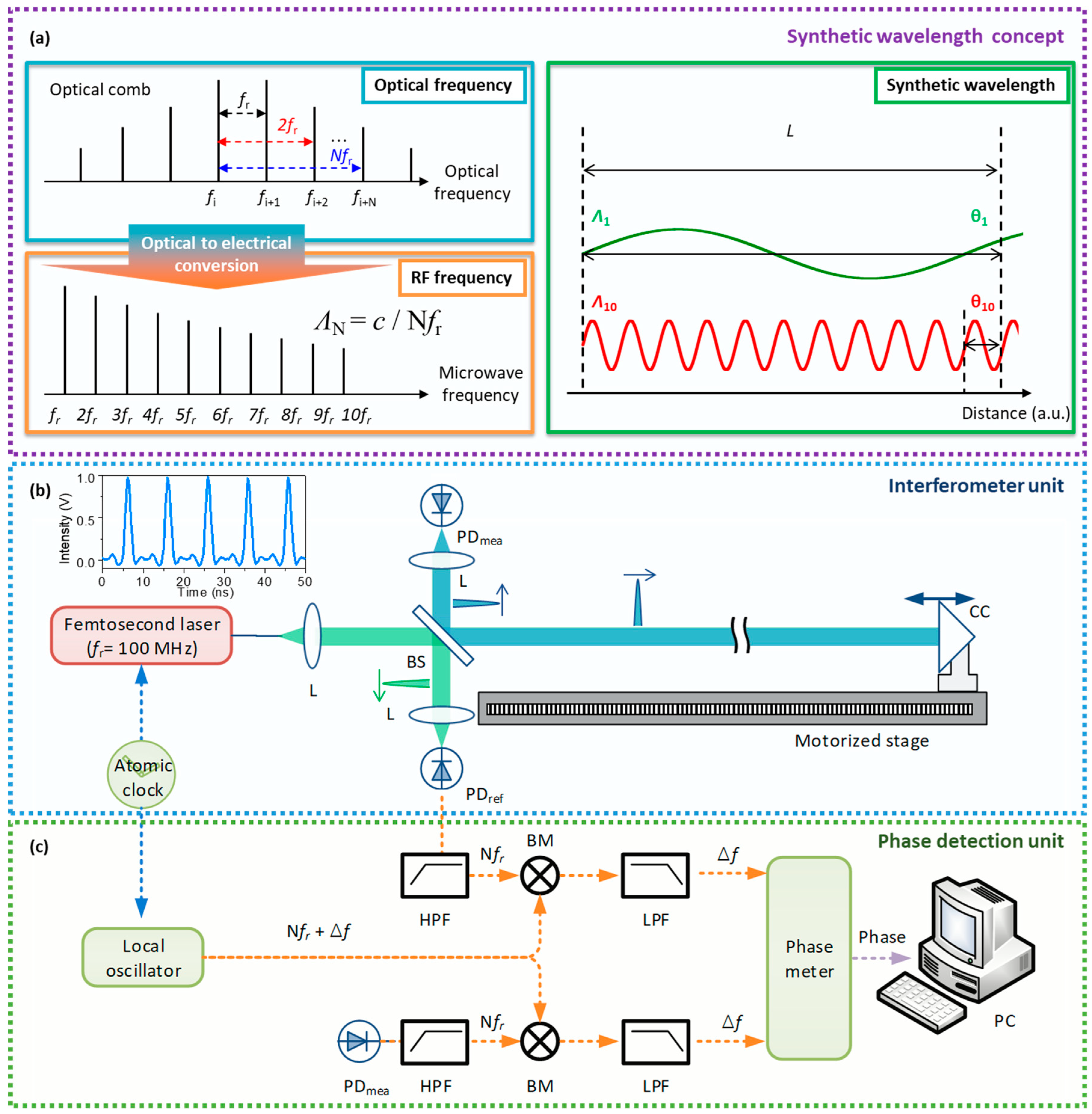
Figure 1. Photonic microwave distance interferometer. (a) Optical spectrum of a mode-locked laser and its radio frequency (RF) synthetic wavelengths. (b) Optical configuration for absolute distance measurement. (c) RF electrical circuit for interferometric phase detection. BM: balanced mixer, BS: beam splitter, c: speed of light in air, CC: corner cube, HPF: high pass filter, L: lens, LPF: low pass filter, PC: personal computer, PD: photodetector, ref: reference, mea: measurement, Δf: beat frequency, fr: pulse repetition rate, Nfr: N-th harmonics of fr, Λ: synthetic wavelength, θ: interferometric phase.
Applsci 10 07649 g001
Figure 2. Measurement repeatability. (a) Measurement fluctuation of a 1-m fixed distance traced over 1000 s along with its histogram. (b) Allan deviation from 0.1 to 100 s averaging.
Applsci 10 07649 g002
Figure 3. Systematic measurement error. (a) Experimental data of measurement errors over a range from 0.5 to 2.5 m. (b) Periodic error vs. and non-periodic error. (c) Cyclic error amplitude vs. unwanted signal ratio (d) Photodiode output amplitude (proportional to the received optical power) in comparison to the non-cyclic error.
Applsci 10 07649 g003
Figure 4. Passive systematic error correction. (a) Mean systematic error (blue) and residual error after passive correction—1 σ line (green) and 2 σ line (orange). (b) Fourier transformed result of the mean error (blue) and corrected error (orange). FFT means a Fourier transformed result.
Applsci 10 07649 g004
Figure 5. Active systematic error correction. (a) Phase measurement circuit with feedback control for signal power compensation. (b) The result of optical power stabilization. (c) Position error after power compensation (blue) and its corrected error (green). BM: balanced mixer, HPF: high pass filter, LPF: low pass filter, PD: photodetector, RF: radio frequency, ref: reference, mea: measurement, fr: pulse repetition rate, PI: proportional integral, STD: standard deviation.
Applsci 10 07649 g005
Publisher’s Note: MDPI stays neutral with regard to jurisdictional claims in published maps and institutional affiliations.