1. Introduction
The use of fibre-reinforced polymers (FRP) to strengthen concrete structures has been steadily gaining popularity over the last decades. The externally bonded reinforcement (EBR) and near-surface mounted (NSM) techniques are currently the most well-known methodologies employed to enhance the load-carrying capacity of civil structures. Standards and guidelines such as the fib Bulletin 90 [
1], the ACI 440.2R-17 [
2], and the CNR-DT 200 R1/2013 [
3] have already approved the design of FRP strengthening systems for concrete structures.
Even though the short-term bond behaviour of EBR and NSM methodologies has been extensively studied over the past decades, less attention has been paid to their behaviour under service conditions. External circumstances, such as sustained loading or environmental temperature conditions, can cause significant damage, either to the concrete [
4,
5,
6] itself or to the strengthening system during its service life, which can then lead to a reduction of the load-carrying capacity, resulting in premature bond failures [
7,
8,
9]. It is extremely important, therefore, to investigate the behaviour of FRP strengthening systems under real service environmental conditions.
The effect of sustained loading in NSM CFRP strengthening systems was experimentally evaluated in Emara et al. [
10] and Gómez et al. [
11] for room conditions. In both studies, sustained loading caused a substantial increase in the relative slip between the CFRP and concrete, although the load applied was much lower than the ultimate load of the bonded joint. From these investigations, numerical models based on the degradation of the bond-slip law of the bonded joint were proposed to predict their sustained loading behaviour.
On the other hand, high service temperatures have been proved to significantly affect the performance of FRP strengthening systems. In general, dramatic decreases in the bond strength and stiffness of the joint have been observed when temperatures are close to the glass transition temperature (
Tg) [
8,
12,
13,
14,
15,
16,
17,
18], along with an increase in the bonded length needed to carry the maximum load [
13,
15], a redistribution in the FRP strain [
13,
16,
18], and a change in the failure mode [
17,
18].
Furthermore, because service temperatures do not remain constant with time in real applications but rather oscillate during the day-night cycle and during the different seasonal weather conditions, it is crucial that the effects such cyclic temperatures might have on the structural response of the bonded joint be investigated. Fernandes et al. [
7] performed durability tests of NSM CFRP-concrete specimens under cyclic temperature (20 to 80 °C) conditions for six months and obtained a significant variation in the stiffness and a similar value of the ultimate load in comparison with the instantaneous values. On the contrary, when Lee et al. [
9,
19] studied the effect cyclic temperature conditions have on concrete elements strengthened with NSM CFRP rods using temperature cycles ranging from −15 to 55 °C they detected a decrease in the ultimate load of the bonded joint as the temperature cycles being applied were increased.
Several other experimental studies focused their investigations on the effects of the combination of sustained loading performance and high service temperatures, evaluating their impact on the activated length, the residual strength, and the stiffness of the bonded joint. Some contributions [
20,
21] have concluded that the combination of high service temperature with sustained loading caused an increase in the overall strength of the EBR bonded joint, while others [
9,
22,
23] observed a reduction in the EBR joint strength.
In the field of NSM strengthening, only a few investigations on the subject of the combination of sustained loading and high service temperatures are to be found in the literature. For instance, Borchert et al. [
24] observed a loss of the load carrying capacity which was attributed to the creep effect caused by the combination of both factors, while Emara et al. [
25] concluded that service conditions greatly affected the bonded joint performance, causing a significant increase in the slip with time between the CFRP and the concrete element. Nevertheless, less attention has been paid to the effect of cyclic environmental conditions, such as day-night cycles, and these may prove crucial for a better understanding of the bond behaviour of FRP strengthening systems.
This paper aims to contribute to the understanding on how steady and cyclic service temperature conditions affect the sustained loading bond response of NSM CFRP-concrete elements through an experimental programme using sustained loading single-shear tests. The effects the service load level, temperature, groove thickness and preconditioning have are presented and discussed. Furthermore, following the sustained loading tests, monotonic tests have been carried out to investigate the residual strength, stiffness and failure mode of the bonded joints.
2. Experimental Programme
Four experimental series (S1 to S4)—each consisting of eight specimens—were performed under sustained loading (ST) and different service temperatures at 55% relative humidity (RH). Two different service loads were applied (15% and 30% of the ultimate load of the NSM CFRP-concrete joint) which represent the range of load values that the CFRP-concrete joint can undergo in a flexural configuration under service conditions. Furthermore, two steady-state and two cyclic service temperatures were programmed. Their bond response was studied by analysing the slip between the CFRP and concrete with time.
The instantaneous bond behaviour of the NSM specimens was experimentally investigated and presented previously by Gómez et al. [
26]. The ultimate loads (
Pu), stiffnesses (
Ke) and failure modes that were obtained have been summarised in
Table 1. Specimens are labelled as
I-
Lb-
tg, where
I stands for instantaneous test, and
Lb and
tg are the bonded length and groove thickness, respectively.
All the specimens that did not fail during the sustained loading (SL) were tested using a monotonic pull-out configuration to investigate the residual mechanical characteristics of the bonded joints and were called post-sustained loading (PSL) specimens.
2.1. Specimen Characteristics
In each experimental series eight NSM CFRP-concrete specimens combining two groove thicknesses (7.5 and 10.0 mm) and two bonded lengths (150 and 225 mm) were loaded under two sustained load levels (15% and 30% of the instantaneous ultimate load,
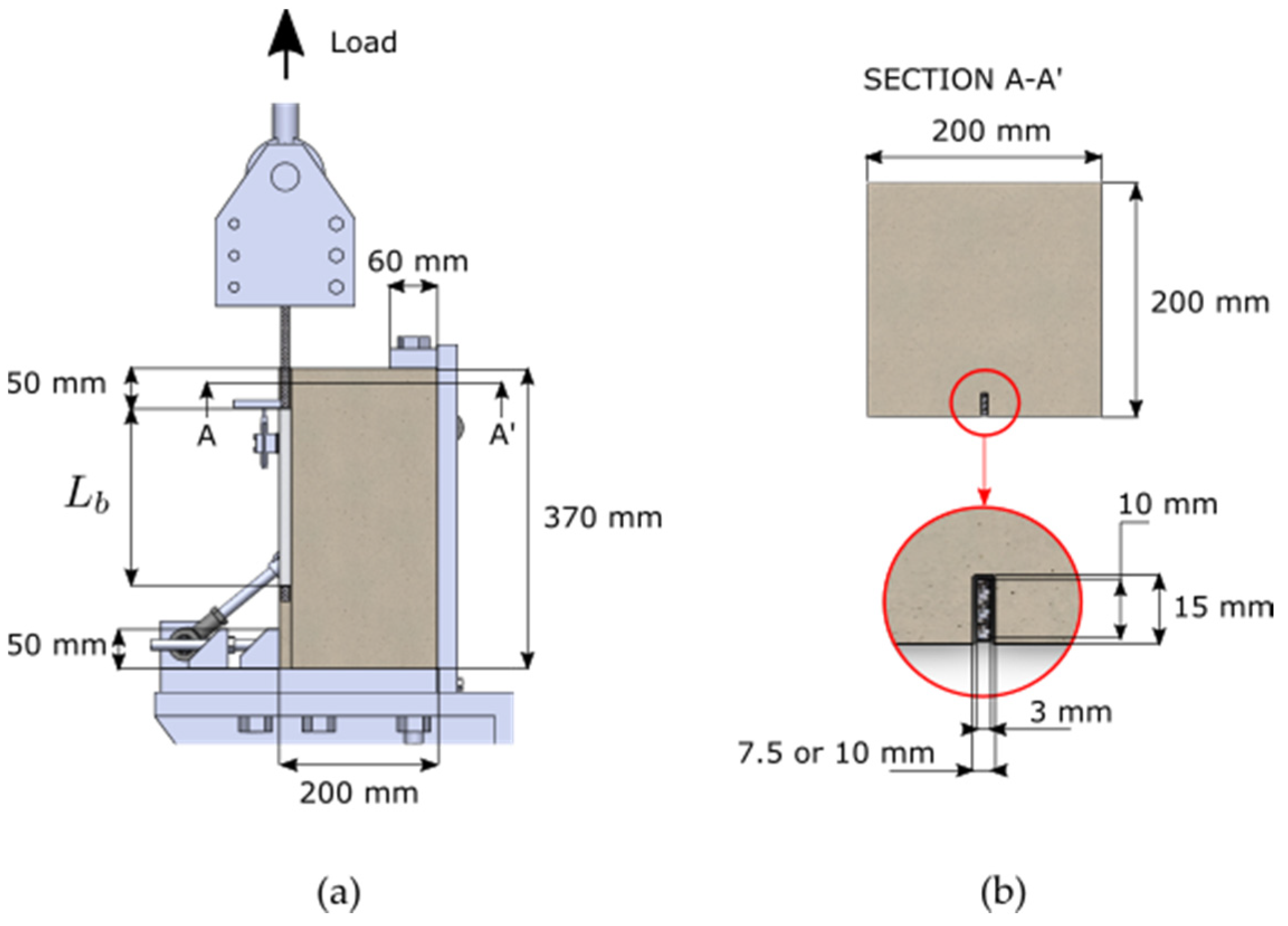
Pu). Concrete blocks measuring 200 mm × 200 mm × 300 mm and 200 mm × 200 mm × 370 mm were used for short and long bonded length specimens, respectively.
Figure 1a shows a lateral view of the setup for the single shear test and
Figure 1b presents a detailed view of the groove dimensions and the CFRP strip into the groove.
For each experimental series, the concrete blocks were cast with a standard ready-mix concrete supplied by a local company and cured for 28 days under laboratory conditions. Once the concrete had cured, 15 mm deep grooves were then cut and cleaned. The adhesive was prepared by mixing a 3:1 ratio of resin and hardener, as indicated by the manufacturer. Next, CFRP strips were carefully introduced into the grooves and then the NSM CFRP-concrete specimens were subsequently cured for 12 days under laboratory conditions before testing.
The specimens under sustained loading were called S-SL-Lb-tg-%Pu, where S stands for the series number, SL for Sustained-load, Lb and tg are the bonded length and groove thickness, respectively, and %Pu the percentage of ultimate load applied as sustained load.
The residual response of the NSM CFRP-concrete joint after SL was evaluated for all the specimens by employing an instantaneous pull-out test until failure at room temperature (20 °C and 55% RH). Each specimen was then called S-PSL-Lb-tg-%Pu, where PSL stands for post-sustained-loading and the rest of the parameters representing the same as those previously defined above. It should be noted that the specimens from series S3-B were those from the S3-A series, therefore, only the S3-B series specimens’ PSL behaviour following the sustained-loading (SL) tests could be studied.
2.2. Material Properties
All the concrete blocks were cast from the same concrete batch. Following the ASTM S3-A69/S3-A69M-10 [
27] and UNE 12390-3 [
28] standards, a concrete compressive strength of 33.0 MPa (with Standard Deviation, SD = 1.8 MPa) and an elastic modulus of 33.1 GPa (SD = 1.6 GPa) were obtained.
CFRP Sika CarboDur S NSM 1030 strips of 10 mm × 3 mm were used. A tensile strength of 3.2 GPa (SD = 68.3 MPa) and an elastic modulus of 169.3 GPa (SD = 13.1 GPa) were obtained following the ISO 527-5 standard [
29]. To measure the thermophysical properties of the adhesive, differential scanning calorimetry (DSC) tests were performed after 12 days of curing at 20 °C [
30]. A
Tg of 53.1 °C and a curing degree (
α) of 96.3% were obtained.
The adhesive used in the experimental campaigns was Sika 30 bi-component epoxy resin, which had been previously characterized according to the ISO 527-2 standard [
31]. The tensile strength and elastic modulus were, respectively, 26.1 MPa (SD = 4.5 MPa) and 10.7 GPa (SD = 471.4 MPa).
2.3. Test Set-up and Instrumentation
All tests were performed using a direct pull-out shear configuration. The test set-up for the sustained loading tests consisted of adapting the set-up applied in the instantaneous characterization of the NSM CFRP-concrete joint [
11] by using a steel lever arm with a magnifying factor of 8.3 (
Figure 2a). For the PSL tests, the instantaneous characterization set-up was used (
Figure 2b).
For the SL tests, the instrumentation consisted of one linear variable differential transformer (LVDT) placed at the loaded end to measure the relative displacement between the CFRP and the concrete, and one strain gauge bonded at the loaded end to register the load applied to the bonded joint. To measure the internal temperature of the bonded joint, a temperature strain gauge was bonded onto the CFRP surface, inside the NSM groove, of a dummy specimen, which was also kept inside the climatic chamber during the tests, in each of the series. Another temperature strain gauge was bonded onto the NSM groove surface of the same dummy specimen to measure the temperature on the specimen’s surface. In the case of the post-sustained loading monotonic tests, the instrumentation consisted of one LVDT placed at the loaded end.
2.4. Sustained Loading Experimental Series
The details of each experimental series are listed in
Table 2, i.e., where the cycle function (steady for constant objective temperature and cyclic for 24 h-periodical temperature cycles), whether the specimens were preconditioned (or not) before loading, the objective temperature in the climate chamber, the temperature measured on the specimen’s surface, the temperature measured inside the NSM groove (attached to the CFRP) and the duration of the test are presented.
In the experimental series S1 (previously presented in Gómez et al. [
11]) and S2, specimens were tested under steady temperatures, while in series S3 and S4, trapezoidal and triangular 24-h temperature cycles, respectively, were applied (
Figure 3). Experimental series S3 was split into two different steps. First, specimens were subjected to an objective temperature cycle ranging between 18.0 and 38.0 °C (S3-A) and then, after 600 h of testing and without any unloading, the same specimens were subjected to a new objective temperature cycle ranging between 22.0 and 43.0 °C (S3-B). Series S1–S3 were subjected to a thermal preconditioning before loading which consisted of acclimatizing the specimens to the objective temperature for seven days. In series S4, the specimens were loaded without undergoing any previous preconditioning stage.
Figure 3 shows the details of the objective temperature (red curve), the temperature on the specimen’s surface (blue curve) and the temperature inside the NSM groove (black curve) for all series. As observed, the temperature on the specimen’s surface was generally lower than the objective temperature for both steady and cyclic temperature series, basically due to thermal inertia effects. Furthermore, in the cyclic temperature series, the mean temperature measured inside the NSM groove was between 1.3 and 3.3 °C lower than on the specimen’s surface, while in the steady temperature cycles this difference did not occur. Finally, in the S3 series, with a trapezoidal shape for the objective temperature, the temperature inside the NSM groove reached higher values than in the S4 series where a triangular shape was programmed as the objective temperature.
3. Sustained Loading Bond Behaviour of NSM CFRP-Concrete Specimens
The evolution of slip with time was obtained from the sustained loading tests in all series, as seen in
Figure 4.
Overall, two different stages were identified in the slip evolution with time for all experimental series: an initial stage with a high non-linear increase in slip and a second stage where the slip evolution tended to increase at a lower and constant rate with time. In the following subsections, the effects of the sustained load level, thermal effects, preconditioning and groove size are discussed.
3.1. Effect of Sustained Load Levels
The effect of sustained load levels can be clearly observed in
Figure 4 for all the experimental series, i.e., as expected, the higher the sustained load, the higher the slip and increment of slip. This effect was observed regardless of the temperature conditioning, bonded length or groove size. Moreover, the specimens under 30%
Pu experienced approximately double the slip than the under 15%
Pu specimens. This linearity in the slip with respect to load was also observed in Emara et al. [
25].
3.2. Thermal Effects
3.2.1. Effect of Steady Temperatures
The effect of different steady temperatures on the slip behaviour can be observed by comparing series S1 (with a steady 18.7 °C inside the NSM groove,
Figure 4a) and S2 (37.7 °C,
Figure 4b). As expected, higher slips were obtained in the S2 series which could be attributed to the effect temperature has on the creep behaviour of the adhesive [
25]. Furthermore, of all the experimental series it was the S2 specimens that showed the highest increments of slip; albeit with the only exception being the S4 specimens which experienced a significant increase in the slip in the first cycles which is attributed to the lack of preconditioning (see
Section 3.2.3). In contrast, series S1, with the lowest temperature, experienced the smallest effect on the creep behaviour of the bonded joint. This behaviour was likewise observed in Emara et al. [
25], where the highest increases of slip were obtained in specimens subjected to the highest temperatures.
3.2.2. Effect of Cyclic Temperatures
The temperature cycles in series S3-A, S3-B and S4 caused important fluctuations in the evolution of slip as a result of the thermal effects on the materials. These slip oscillations were relatively high in comparison with the increase in slip due to the sustained loading effect, especially in those cases under 15%
Pu where the evolution of slip was small. In
Figure 5, the comparison of the slip evolution between the S1 (with a steady temperature in the NSM groove of 18.7 °C) and S3-A (with a cyclic temperature of 17.8–33.9 °C) series is presented.
It can be observed that, in general, similar mean evolutions of slip were obtained in both series despite the temperature cycles applied in S3-A. This could be explained by the fact that in series S3-A the average temperature measured in the NSM groove (25.6 °C) was relatively far away from the Tg of the adhesive (53.1 °C), thus leading to a small influence in comparison with the effect of sustained loading.
On the other hand,
Figure 6 depicts a comparison between the evolution of slip in the S3-A series with its trapezoidal cyclic temperature between 17.8 and 33.9 °C and a mean temperature of 25.6 °C, and the S3-B with the same shape for the temperature cycles but ranging between 24.6 and 39.2 °C and with a mean value of 31.3 °C.
Comparison between these series seems to indicate a somewhat greater influence of temperature in the S3-B series, mainly in those cases loaded at 30%
Pu, which could be attributed to the higher mean and maximum temperatures in the S3-B series and being closer to the
Tg of the adhesive. Finally,
Figure 7 depicts the comparison of the slip evolution with time between S2, (with a steady temperature of 37.7 °C) and S3-B (with a trapezoidal cyclic temperature between 24.6 and 39.2 °C and a mean temperature of 31.3 °C).
The lower values of slip obtained in the S3-B series could be attributed to the fact that the mean temperature in S3-B was 6.4 °C lower than that of the S2 series, even though the peak temperature of the cycle was slightly higher than the steady temperature in S2 (see
Table 2). To sum up, in general terms the effect the temperature exerted on the sustained loading behaviour became more significant as the average temperature in the NSM CFRP-concrete joint moved closer to the
Tg of the adhesive.
3.2.3. Effect of Preconditioning
As shown in
Figure 4, results from series S4 indicate that the thermal preconditioning of the specimens had a significant effect—particularly important in the first temperature cycles—on the bonded joint response. This behaviour was also observed in [
24] where a very high increase in FRP strain was observed in specimens under a sustained load of 40%
Pu, when the temperature was raised from 20 to 50 °C. However, after around three cycles, the slip evolution stabilized and similar increases of slip with time were obtained among the S1, S3-A and S4 series, probably because the average temperatures inside the NSM groove were relatively low (18.7 °C for series S1, 25.6 °C for S3-A and 26.8 °C for S4).
3.3. Effect of Groove Thickness
While in the previous sections the comparisons were made among different series, in this section the effect of the groove thickness is analysed. Since the instantaneous slip caused by the percentage of sustained load is different for 7.5 and 10 mm groove thicknesses, to better compare its effect, the evolution of the slip increase, defined as the slip occurring after the instantaneous slip (Δs), is presented in
Figure 8 for the different series. For series S4 (
Figure 8d), the instantaneous slip was taken three first cycles after the test started to avoid the effect of the preconditioning.
In general, the effect of the groove thickness was small in comparison with other parameters such as the sustained load level. At t = 1000 h, the maximum difference in slip evolution between the specimens with different groove thicknesses was found in S2 series for specimens loaded at 30% Pu and with a bonded length of 225 mm. This was equal to 0.016 mm.
In series S1, slightly higher increases of slip were obtained in specimens with narrower grooves, probably because more sustained loads were applied to the 7.5 mm specimens compared to the 10 mm ones [
11]. However, in the S2 and S3-B series, where temperature had a more significant effect, as the average temperature increased, the 10 mm specimens experienced higher slips than the 7.5 mm specimens did, especially those under 30%
Pu. This might be attributed to more of the adhesive surface being in contact with the ambient temperature, thus causing greater damage to the bonded joint.
4. Post-Sustained Loading Bond Behaviour of NSM CFRP-Concrete Specimens
The residual bond response of the NSM CFRP-concrete specimens after sustained loading, in terms of ultimate load (
Pu,PSL), stiffness (
Ke,PSL) and failure mode, was studied using instantaneous pull-out tests until failure.
Table 3 presents the ratio of
Pu,PSL, obtained from the PSL tests, with respect to the value of the instantaneous
Pu for each experimental series. Due to gripping/un-gripping operations during long-term and subsequent pull-out tests, four specimens experienced a premature FRP failure in the zone of the gripping system (S1-PSL-225-10-15, S1-PSL-225-10-30, S1-PSL-225-7.5-30, S2-PSL-150-7.5-15). While the results from these specimens have been considered non-representative and consequently removed from the analysis of ultimate load, they were, however, retained for the stiffness comparisons (since the initial part of the curve could be used).
4.1. Effect on the Ultimate Load and Failure Mode
Overall, no significant differences were obtained in the PSL ultimate load compared to the instantaneous characterization values (the mean ratio of all specimens being equal to 0.99). Likewise, ratios close to the unity were observed when analysing the global results of groups of specimens under either 15% or 30% Pu.
Some aspects should be highlighted when analysing the different series. For instance, series S1 does not present any significant effects from the sustained loading conditions, despite presenting a mean global reduction of
Pu,PSL lower than 1%, and no relevant differences being observed either for load values or bonded length and groove thickness. Some differences, however, can be identified in series S2 and S3-B. For example, series S2 presents a mean global increment of 6.3% (probably due to the post-curing effect on the adhesive) with similar values for the two load levels, and a slightly more pronounced increment for the 10 mm groove thickness (9%) than for the 7.5 mm thickness (3%). Meanwhile, for S3-B in terms of temperature cycles, an 8% global reduction can be seen. This influence is greater in the specimens loaded at 30%
Pu (12% reduction) than in those loaded at 15%
Pu (4% reduction), which might indicate that there the temperature cycles exert some influence, albeit mainly for the higher sustained load value. On the other hand, with a final global mean value of the ratio close to the unity, no clear tendencies are observed in series S4 with temperature cycles but without preconditioning. The results presented are in accordance with the observations made in Fernandes et al. [
7], where small decreases of the ultimate load were observed in specimens subjected to outdoor environmental conditions (around 12%).
As for the failure mode of the NSM CFRP-concrete joint, no differences were generally obtained in comparison with the instantaneous characterization, with the main failure mode being the cohesive failure in the concrete for specimens with a 7.5 mm groove thickness and failure in the FRP-adhesive interface for specimens with a 10 mm groove thickness. However, specimens S3B-PSL-150-10-30 and S3B-PSL-225-10-30 experienced a failure in the adhesive-concrete (A-C) interface, which indicates a decrease in the bond at the interface.
Figure 9 shows two examples of failure modes obtained from PSL tests: a failure in the A-C interface obtained in specimen S3-B-PSL-225-10-30 (
Figure 9a), and a cohesive concrete failure obtained in specimen S3-B-PSL-225-7.5-30 (
Figure 9b).
4.2. Effect on the Stiffness
The PSL load-slip load is illustrated in
Figure 10 (black curve) together with the load-slip curves obtained in the instantaneous characterization (blue curve) for specimens PSL-225-10-30 from each series (S1, S2, S3-B and S4). Note that in
Figure 10a, the specimen experienced a premature failure in the CFRP strip (marked with an X in
Figure 10). A reduction in the initial stiffness was observed in all specimens, but there was an overall recovery as the load in the instantaneous test surpassed the value of the sustained loading. This effect is attributed to the unloading-loading path as a combination of damage and creep effects. During the sustained loading tests, the activated length was lower than the total bonded length (
Lb) and, consequently, the effects of sustained loading affected only part of
Lb. Subsequently, as the load was increased in the monotonic PSL test, as the load increased, the activated length increased and moved towards the free end and joint stiffness was recovered because this zone had not been activated during the sustained loading test.
When the observed values of all the specimens are considered, the global overall reduction of the stiffness was about 14% (see
Table 3). This reduction was more noticeable for specimens loaded under 30% of the initial ultimate load, and, in particular, those from series S2, thus showing that the higher the sustained load level and average temperature are, the greater the decrease in stiffness is. These observations agree with the results presented in Fernandes et al. [
7], where a significant decrease in the stiffness of the bonded joint was observed in specimens under cyclic environmental conditions.
5. Conclusions
The present work experimentally studied the bond behaviour of an NSM CFRP-concrete joint under sustained loading and different service temperature conditions. Four experimental campaigns consisting of eight NSM CFRP-concrete pull-out single shear tests (SL tests) were performed under sustained loading for 1000 h inside a climatic chamber at different temperature conditions, combining steady and cyclic objective temperatures. After that, post-sustained loading tests (PSL tests), where the specimens were tested under monotonic loading until failure, were carried out.
From the SL tests the following conclusions can be drawn:
Overall, the slip values obtained in specimens under 15% and 30% Pu were proportional to the applied load;
Similar slips were obtained in specimens with short and long bonded lengths under a sustained loading level of 15% Pu;
Higher slips were obtained in the 10 mm grooved specimens in comparison with the 7.5 mm grooved specimens under high steady temperatures;
Significant slip oscillations, caused by the thermal expansion of the materials, were observed in series with temperature cycles;
As the mean temperature of the thermal cycle increased, so too did the slip at the loaded end;
Specimens under temperature cycles (S3-A, S3-B and S4) experienced increases of slip that ranged between S1 and S2 slips, since the temperatures in the NSM groove fell between 20 and 40 °C;
The decisive effect of the preconditioning cycles was observed during the initial loading days as the specimens that had been submitted to preconditioning temperature cycles experienced lower increases in slip during the first temperature cycles.
From the PSL tests the following conclusions can be drawn:
The ratio of the PSL ultimate load with respect to the initial instantaneous ultimate load was globally close to unity. However, some differences were observed in series S2 with its global increment of 6.3% and in series S3-B with a global reduction of 8%;
Overall, no change in the failure modes were observed in the instantaneous post-sustained loading tests;
A global reduction in the initial stiffness in the load-slip curve was observed, followed by its recovery at higher loads as the load of the PSL test surpassed the value of the sustained loading.
During their service life, civil structures are submitted to a combination of sustained loading and cyclic environmental conditions. This study has helped to appreciate and understand the effect thermal cycles have in constantly loaded CFRP-concrete joints. The bonded joints have been shown to be affected by creep and have their mechanical properties reduced. Therefore, it can be concluded that environmental conditions must be taken into account when designing of CFRP strengthened civil structures.
While this study limited the sustained loading tests to 1000 h, further studies would need to extend this further, especially for higher average temperatures where the high increases of slip were observed in this work.


