Abstract
The authors developed two types of block systems, consisting only of main and key blocks, without joint mortar, to improve the in- and out-of-plane seismic performances and enhance the workability. Two types of block systems have different key block shapes. One is the peanuts shape, and the other is the H shape. The proposed block systems have a half-height difference between the main and key blocks, to significantly improve seismic performance in in- and out-of-plane directions, compared to typical masonry wall with joint mortar. In this study, in order to evaluate the out-of-plane seismic performance of the proposed block systems, two types of block walls are experimentally investigated, including the typical block wall. Firstly, the shaking table tests are carried out to investigate the fundamental out-of-plane behaviors of three specimens. Next, four-point bending tests are planned to evaluate the out-of-plane seismic performance, since all specimens do not occur the out-of-plane collapse in the shaking table tests from the preliminary calculation. In this paper, the development of predominant period, profiles of acceleration and displacement, and maximum tensile strength of each specimen are discussed in detail. As a result, the maximum loads of the proposed block walls were about three to four times that of the typical block wall. This result means that the proposed block system has significantly improved seismic performance in the out-of-plane direction.
1. Introduction
Unreinforced masonry (URM) buildings are the most representative construction system, since the early ages of mankind. Most of them are constructed without the consideration of earthquake design requirements or reference to any particular design code. It is common that total or partial collapse of URM buildings occurs during an earthquake, due to poor quality of materials and construction technology, as shown in Figure 1 and Figure 2 (e.g., [1,2,3,4,5,6]). The low tensile strength, low ductility, and low ability to dissipate energy are the main reasons for limiting the use of URM in middle- and high-seismicity regions. On the other hand, masonry has several advantages as a structural material, such as thermal and acoustic efficiency, economy, simple construction technology, excellent fire behavior, and, usually, low embedded energy. Masonry has good durability and adequate performance, with respect to healthy indoor environment, and can be effectively considered as an alternative low-cost construction solution to low to medium rise residential buildings.
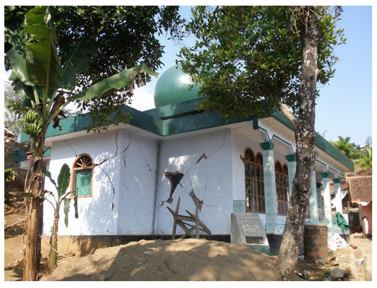
Figure 1.
Masonry wall damage of West Java earthquake, Indonesia (2009).
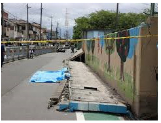
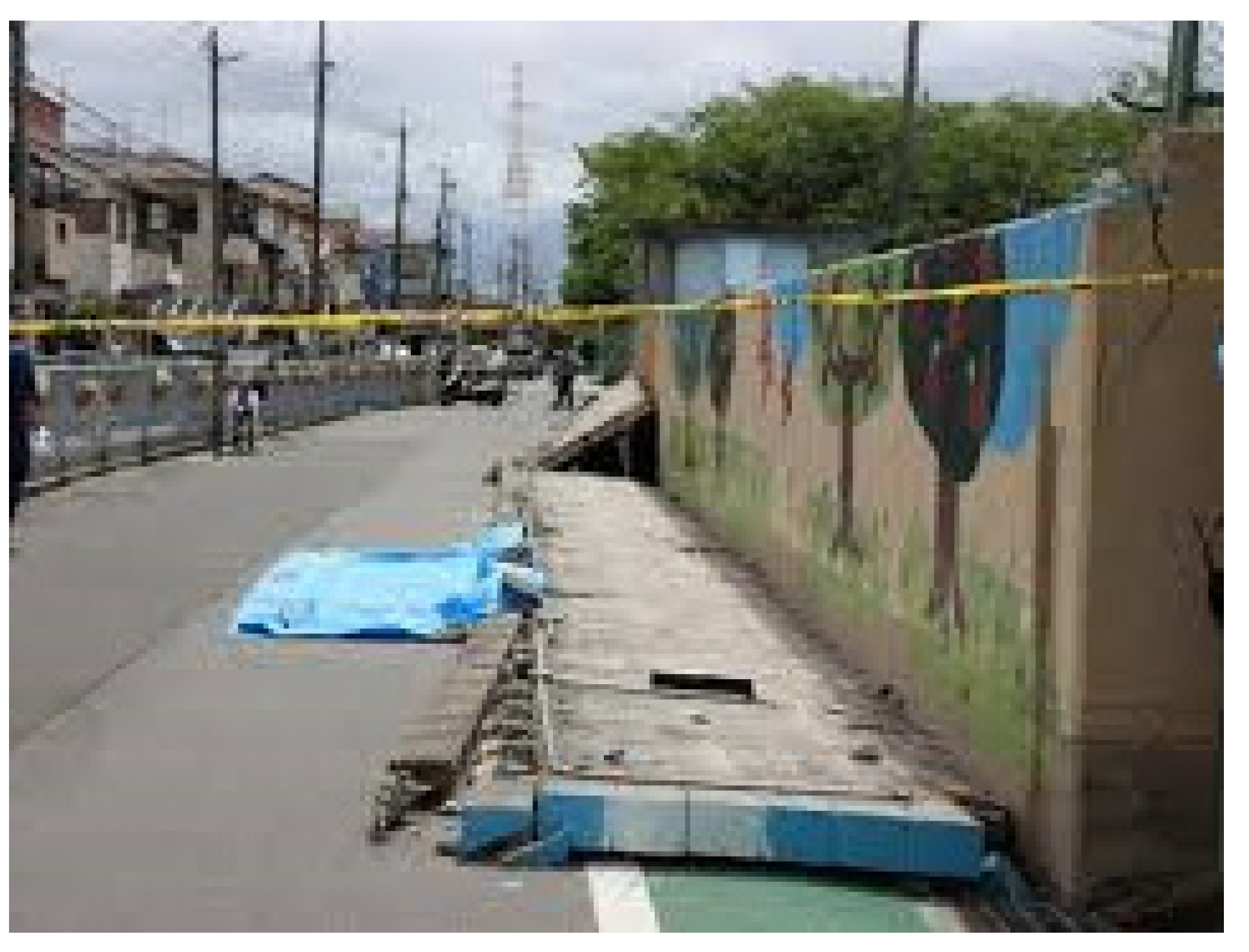
Figure 2.
Masonry wall damage of Northern Osaka earthquake, Japan (2018).
Increasing interest in this construction technique, in the last few decades, has resulted in many experimental tests on in-plane URM sub-assemblages [7,8,9,10,11] and in-plane URM buildings [12,13,14,15,16,17,18]. These studies have provided significantly valuable insights into in-plane seismic performance on URM buildings.
On the other hand, in recent decades, there has been an increasing number of investigations focusing on the out-of-plane behavior (e.g., [19,20,21,22]). Despite the fact that masonry walls are widely used in all over the world, there is only a limited number of experimental studies addressing the out-of-plane behavior of masonry walls [23,24]. Thus, the knowledge of their behavior and design provisions is limited. In general, URM walls exposed to horizontal loads perpendicular to their plane are the most vulnerable elements, in terms of failure mechanisms, as evidenced by post-earthquake damage observations of both public and private buildings [13,14,16,17,18,25]. Due to the out-of-plane vulnerability of URM walls, and the need to understand their behavior, a few experimental studies have been conducted in the past (e.g., [3,4,26,27,28,29]).
Furthermore, some studies on mortar-free masonry units, considering the interlocking mechanism, have been conducted (e.g., [30,31,32,33]). However, most of the studies are on brick units with unevenness; there is no study targeting block units, this study does.
Under these backgrounds, the authors developed two types of new block systems, consisting only of main and key blocks, without joint mortar, in consideration of seismic performance and workability. Two types of block systems have different key block shapes. One is the peanuts shape, and the other is the H shape. It is expected that the proposed masonry wall system will be applied mainly to low-rise masonry houses, masonry fences, and infilled masonry walls in developing countries.
In the previous study, the proposed two types of concrete block walls, as well as a typical concrete block walls, were experimentally investigated to evaluate the in-plane seismic performance. In the tests, full-scale, single-story specimens were tested under static cyclic in-plane loading, and failure patterns and cracks were carefully observed [34].
In this study, in order to evaluate the out-of-plane seismic performance of the proposed block systems, two types of the proposed block walls were experimentally investigated, including the typical block wall. Firstly, the shaking table tests were carried out to investigate the fundamental, out-of-plane behaviors of three specimens. Next, four-point bending tests were planned to evaluate the maximum tensile strength of out-of-plane direction of each specimen, since all specimens do not occur the out-of-plane collapse in the shaking table tests from the preliminary calculation. In this paper, the development of predominant period, profiles of acceleration and displacement, and maximum tensile strength of each specimen are discussed in detail.
2. Proposed Block Systems and Material Characteristics
2.1. Proposed Block Systems
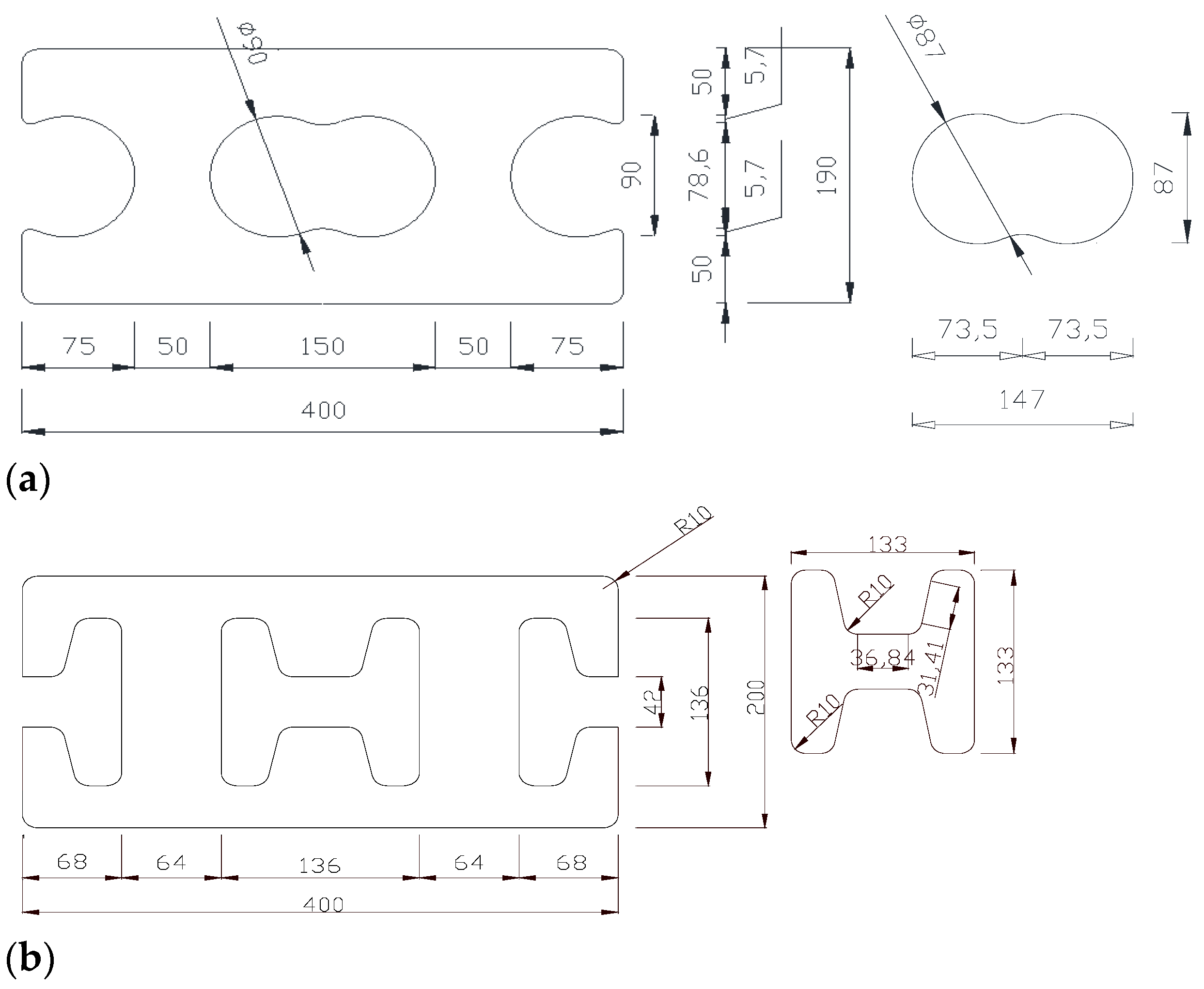
The authors developed two types of concrete blocks to improve the seismic performance, in both the in- and out-of-plane directions, and enhance the workability, without the joint mortar [35]. The two types of concrete blocks only consist of main and key blocks, and they have different key block shapes. One is the peanuts shape and the other is the H shape, as shown in Figure 3.
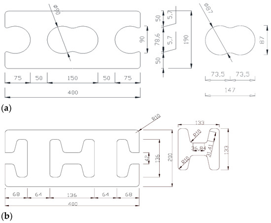
Figure 3.
Two types of concrete block systems (unit: mm): (a) peanuts-shaped concrete block; (b) H-shaped concrete block.
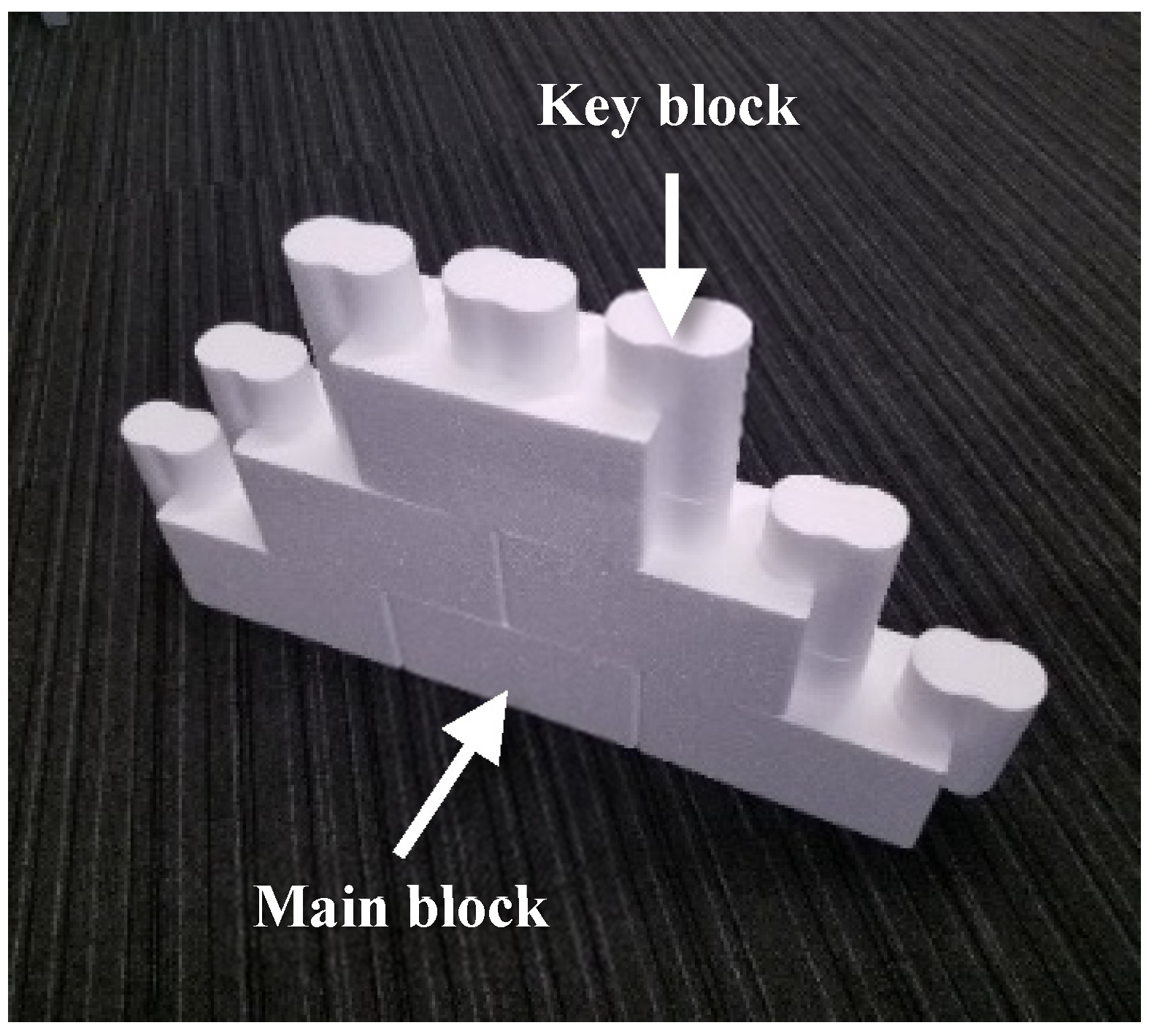
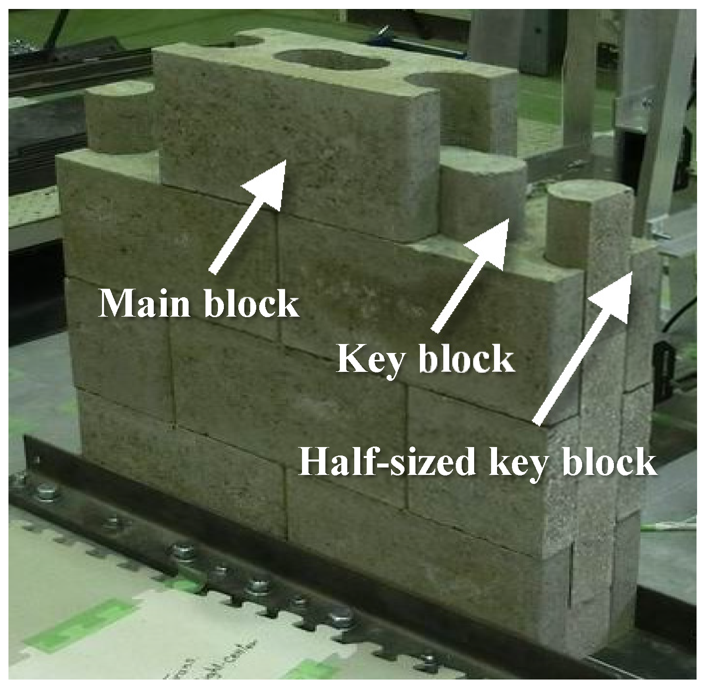
Since the masonry unit may expand in the process of demolding and curing, a gap of 1.5 mm was inserted between the main and key blocks, in consideration of these production errors, as shown in Figure 3. As can be found in Figure 4 and Figure 5, the proposed block systems have half-height difference between the main and the key block. The main blocks, on both sides of the wall, have half-sized key blocks, as shown in Figure 5. Although the behavior of the masonry wall in the in- and the out-of-plane directions are different, a high seismic performance in both directions can be expected because of the height difference formed in the interlocking mechanism.
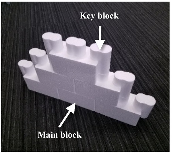
Figure 4.
Construction of the peanuts-shaped block wall using styrofoam model.
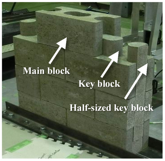
Figure 5.
Construction of the peanuts-shaped concrete block wall specimen.
2.2. Material Characteristics
Each concrete block’s material test results are shown in Table 1 (the average values of three samples are shown in the table). The typical concrete block and peanut-shaped concrete block were made by the normal cement-to-sand-to-water ratio of 1:3:0.5 used in Korea. However, since the H-shaped concrete block has a higher cement ratio, the compressive strength is the highest value among the three concrete blocks, as shown in Table 1. The typical concrete block has three hollows inside and a half-sized hollow on both ends. On the other hand, the peanut-shaped concrete block has the key blocks in hollow parts of the main block. Therefore, the compressive strength of the peanut-shaped concrete block is higher than that of the typical concrete block, because it is divided by the whole area, including the hollow parts (=390 mm × 190 mm), and not the net area excluding the hollow parts, as shown in Table 1. The weights of the typical concrete block, peanut-shaped concrete block, and the H-shaped concrete block, including the key blocks, are 0.2, 0.3, and 0.36 kN, respectively. The compressive strength of mortar is 45.1 N/mm2.

Table 1.
Mechanical properties of each concrete block.
3. Shaking Table Tests
As the first experimental series, in order to investigate the fundamental dynamic out-of-plane behaviors, the shaking table tests were carried out. The details of the tests and results are described below.
3.1. Test Specimens
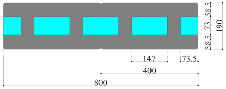
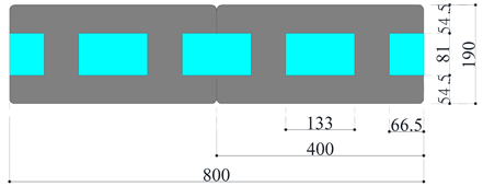
In this study, three single-story, full-height, narrow specimens were designed and fabricated supposing the single-story storage building, as shown in Figure 6: (a) typical concrete block wall specimen with joint mortar (Specimen CB); (b) seismic block wall with H-shaped key block without joint mortar (Specimen HS); (c) seismic block wall with peanuts-shaped key block without joint mortar (Specimen PS). Their dimensions were approximately 2000 × 800 × 190 mm (10 × 2 × 1 layers) in height, length, and thickness, respectively. In this test, due to the restrictions of the experimental equipment, only the central part (2 layers) of the wide wall was considered, which has larger out-of-plane deformation because it is less affected by the transverse wall.
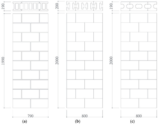
Figure 6.
Details of typical and proposed concrete block wall specimens (unit: mm): (a) Specimen CB; (b) Specimen HS; (c) Specimen PS.
The typical concrete block wall can resist only friction force to the horizontal load after losing the adhesive force between concrete block and joint mortar. On the other hand, the proposed concrete block wall systems are expected to have higher deformability, due to the interlocking mechanism between the main and the key blocks, as shown in Figure 4 and Figure 5.
3.2. Test Setup and Measurement System
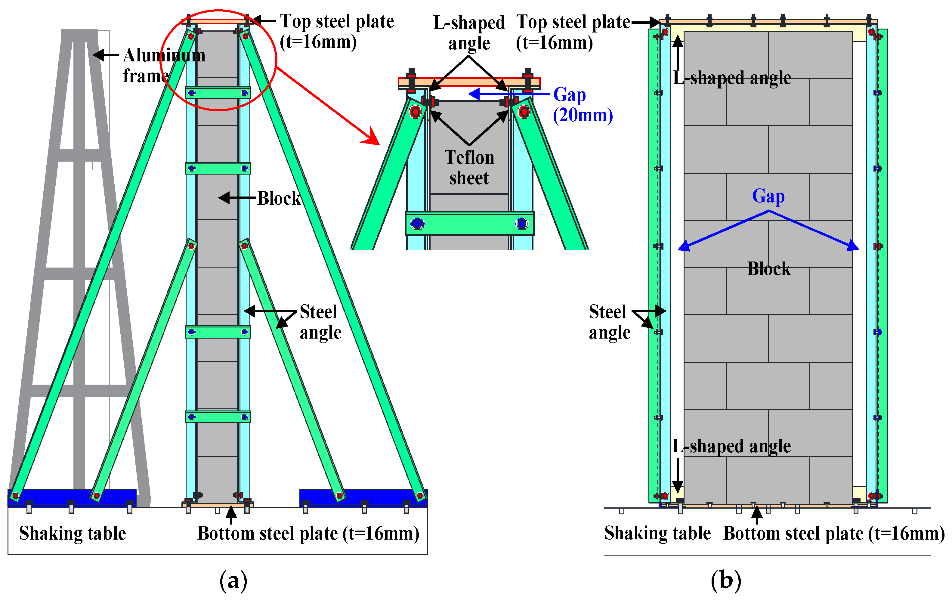
The test setup of the shaking table test is shown in Figure 7. Masonry walls are generally fixed to the slab and beam with mortar at the top and bottom, and the out-of-plane behavior of the wall is formed by the behaviors of the building and the wall itself. In this test, due to the restrictions of the experiment equipment, the behavior of the building was not reproduced, and only the out-of-plane behavior of the wall itself was considered. In order to reproduce this constraint, the specimen was built within the steel frames, as shown in Figure 7. To avoid the development of vertical force on the specimen, due to vertical confinement by the steel frame, a vertical gap of approximately 20 mm was left between the specimen and the top steel plate, whereas the specimen was tightly sandwiched by the rigid L-shaped angles to prevent horizontal slip of the specimen on/at the bottom/top steel plates during excitation. Thus, a roller condition with a freedom in the vertical direction was created at the top by inserting Teflon sheet between the L-shaped angle and the block wall, preventing vertical friction.
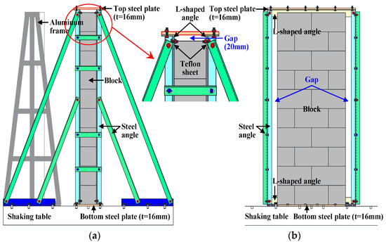
Figure 7.
Shaking table test setup: (a) side view; (b) elevation view.
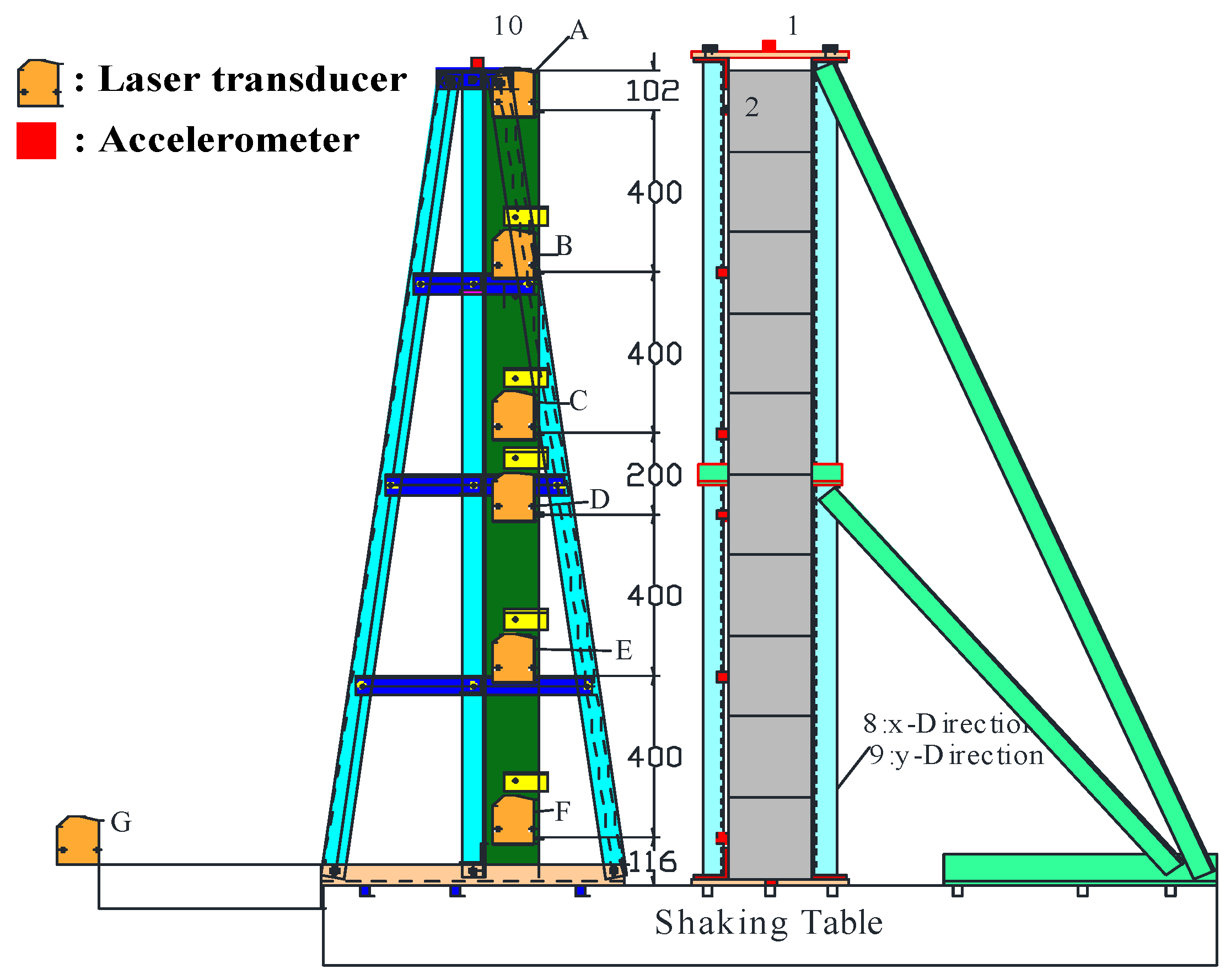
A shaking table of 2 × 2 m was used for the test. It had a maximum earthquake acceleration of 8.9 m/s2, with a restricting weight of 1000 kg. To measure displacement and acceleration over the specimen’s height during the test, six laser transducers and ten accelerometers were installed at different locations, as shown in Figure 8 and Figure 9.

Figure 8.
Measurement system.
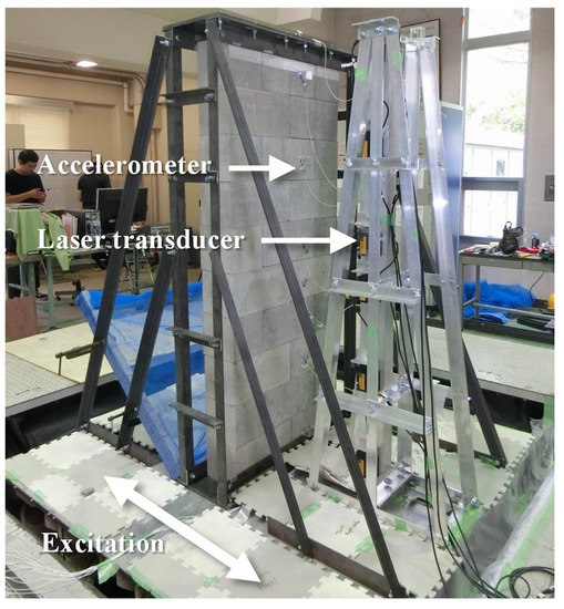
Figure 9.
Overall view of test setup.
3.3. Test Program
In the current seismic design provisions of Korea, a response spectrum of Sa with 5% of critical damping shown in Equation (1) can be obtained by the spectral response acceleration at short-period parameter of SDS and the spectral response acceleration at one second of SD1 shown in Equations (4) and (5), respectively [36]. Figure 10 shows the spectral response acceleration determined by Equation (1). The parameters SDS and SD1 were determined from Table 2, Table 3, Table 4 and Table 5, respectively. In this study, site class SD, at seismic zone I, was selected, since the soil type of Korea mainly consists of stiff soil.
where T0 and TS are given by Equations (2) and (3).
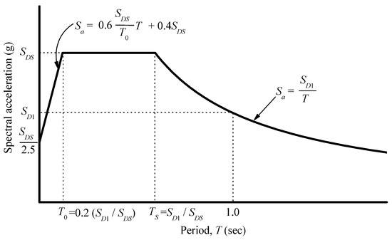
Figure 10.
Design acceleration response spectrum in Korea.
Table 2.
Soil amplification parameter at short-period, Fa.
Table 3.
Soil amplification parameter at one second, Fv.
Table 4.
Site classes in Korea.
Table 5.
Seismic zone factor corresponding to each zone.
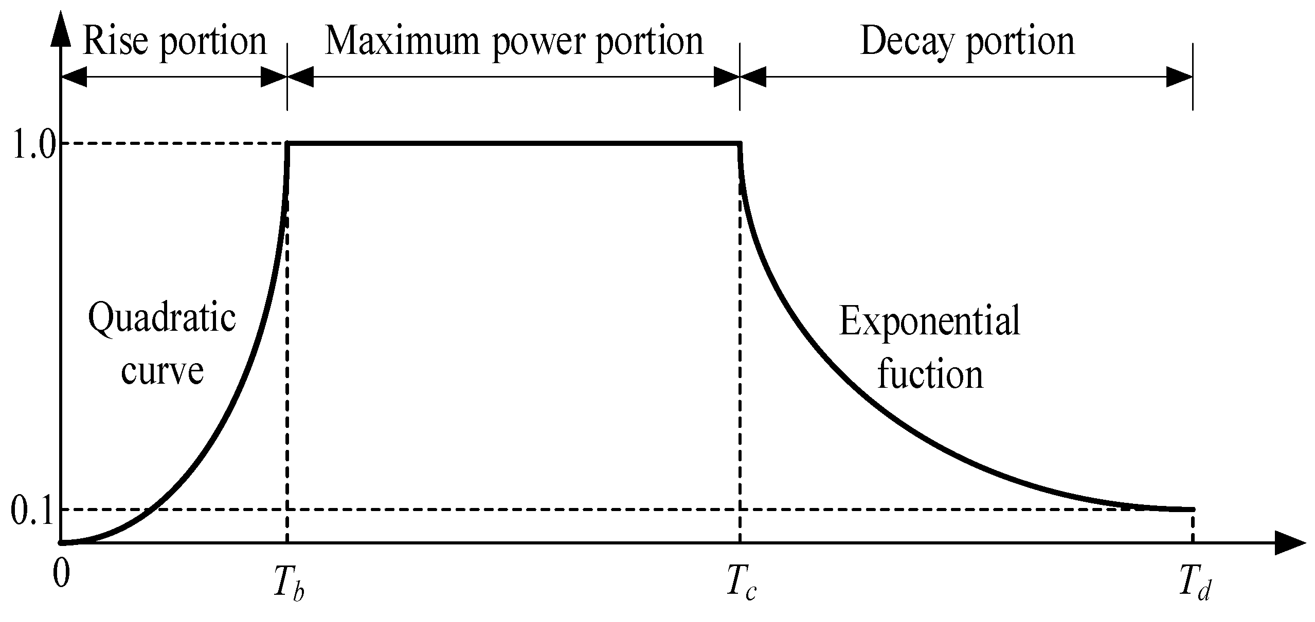
In this study, since the earthquakes of maximum acceleration level, specified in the current seismic design provisions of Korea, have not occurred, a random Fourier phase spectrum and deterministic time-envelope function were used to create an artificial seismic wave. The duration envelope function of an artificial seismic wave used the method suggested by a previous study, as shown in Figure 11 and Equations (6)–(12) [37]. The magnitude of an earthquake, to determine the duration envelope function, was set to M = 8.0, considering the maximum seismic intensity that can occur in Korea in the future.

Figure 11.
Duration envelope function.
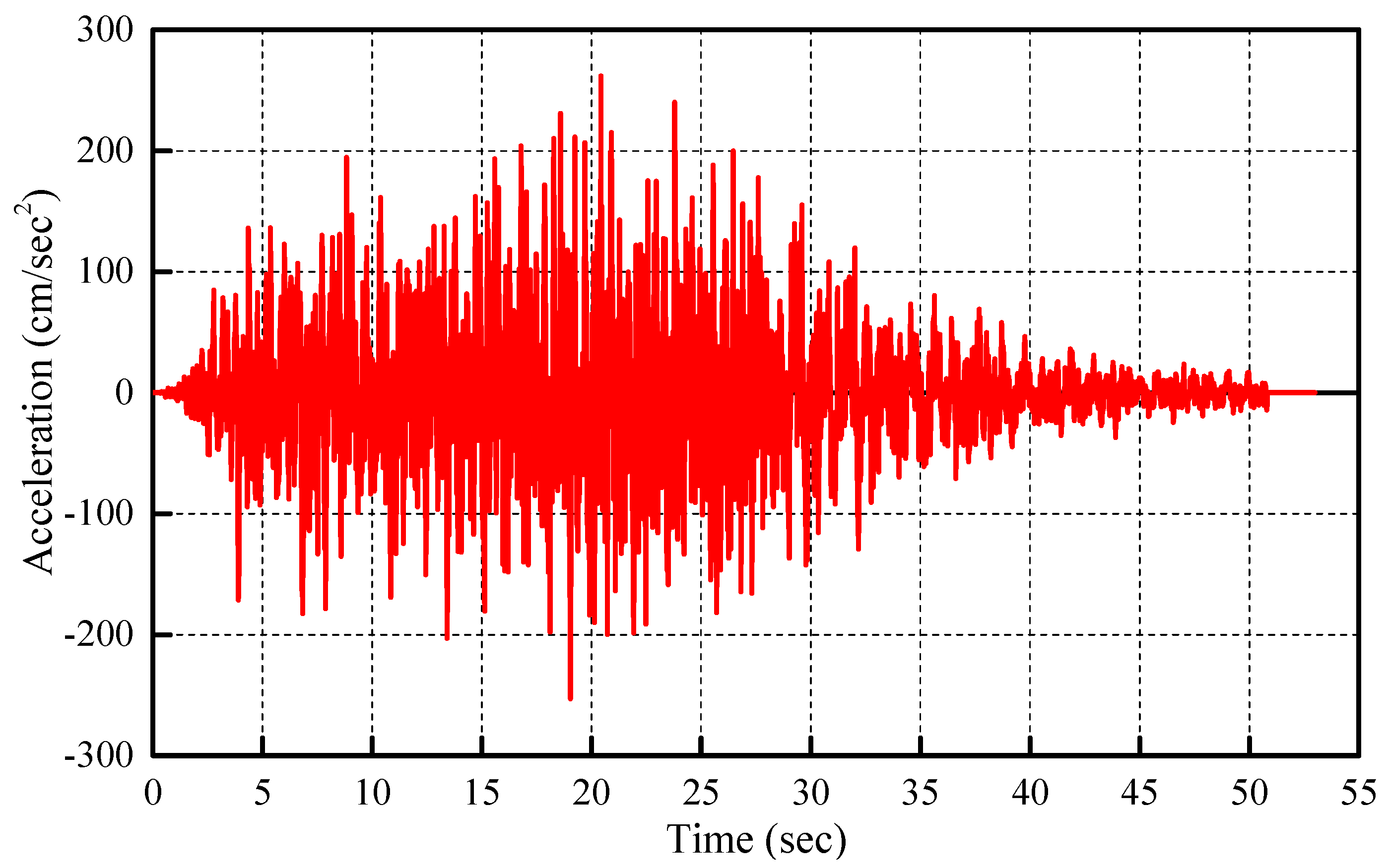
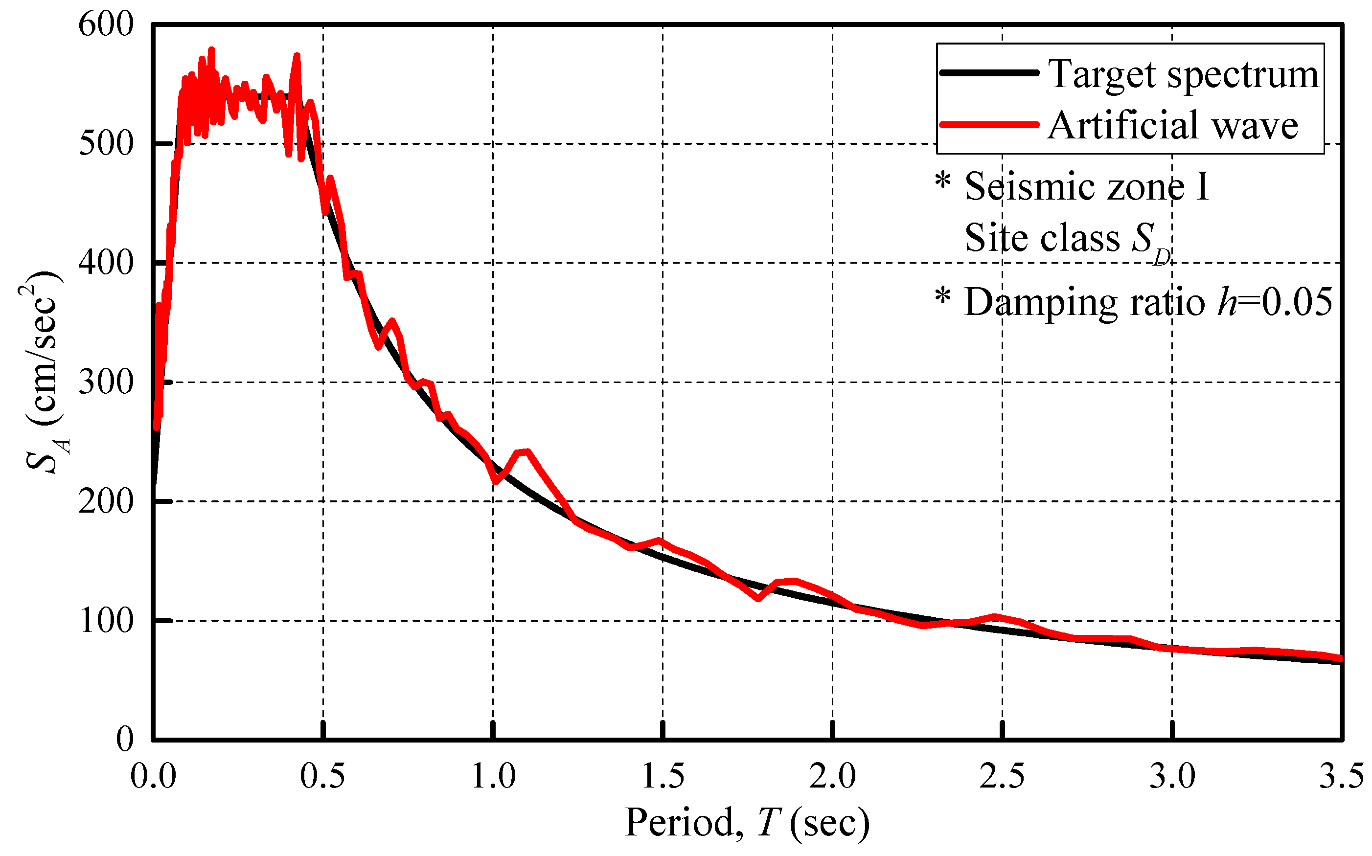
Figure 12 shows the artificial seismic wave, obtained based on the above process, and the maximum acceleration is approximately 2.5 m/s2. Figure 13 shows the elastic acceleration response spectra of artificial ground motions, with 5% of critical damping, corresponding to the design response spectrum at seismic zone 1 and site class SD. In addition, the test was performed under 12 input stages, i.e., 10% (0.25 m/s2), 30% (0.75 m/s2), 50% (1.25 m/s2), 75% (1.88 m/s2), 100% (2.5 m/s2), 120% (3.0 m/s2), 150% (3.75 m/s2), and 160% (4.0 m/s2), of 5 times of the artificial seismic wave.
where
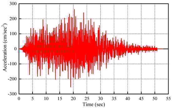
Figure 12.
Artificial seismic wave.
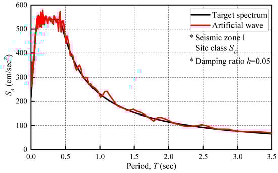
Figure 13.
Elastic acceleration spectra of artificial ground motions.
- Td: Excitation duration of an earthquake (s);
- M: Magnitude of an earthquake (M = 8.0, herein).
3.4. Experimental Results of Shaking Table Tests
3.4.1. Failure Patterns
Figure 14 shows the failure patterns of each specimen after final excitation. As shown in the figure, in Specimen CB, the cracks occurred at the top bed joint mortar and head joint mortar during 150% (3.75 m/s2) and 160% (4.0 m/s2) stages, respectively. Whereas in Specimens HB and PB without joint mortar, no damage occurred, including the block unit, until the final excitation.
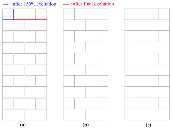
Figure 14.
Final failure patterns: (a) Specimen CB; (b) Specimen HS; (c) Specimen PS.
3.4.2. Development of Predominant Periods
The predominant period of each specimen was calculated using the white noise data input after the excitation of each stage. The development of the predominant period of each specimen is shown in Figure 15. As the maximum acceleration level increases, the damage of a wall generally progresses, and the predominant period increases. However, in this test, no extension of the predominant period was observed any specimen, as shown in Figure 15. This result is consistent with the fact that there was no noticeable damage to each specimen until the final excitation. Furthermore, since there is a gap between the main and key blocks in the proposed block system, the periods of Specimen HS and PS are longer than that of Specimen CS in all stages.
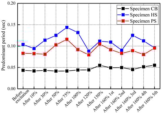
Figure 15.
Development of predominant period of each specimen.
3.4.3. Acceleration and Displacement Profiles
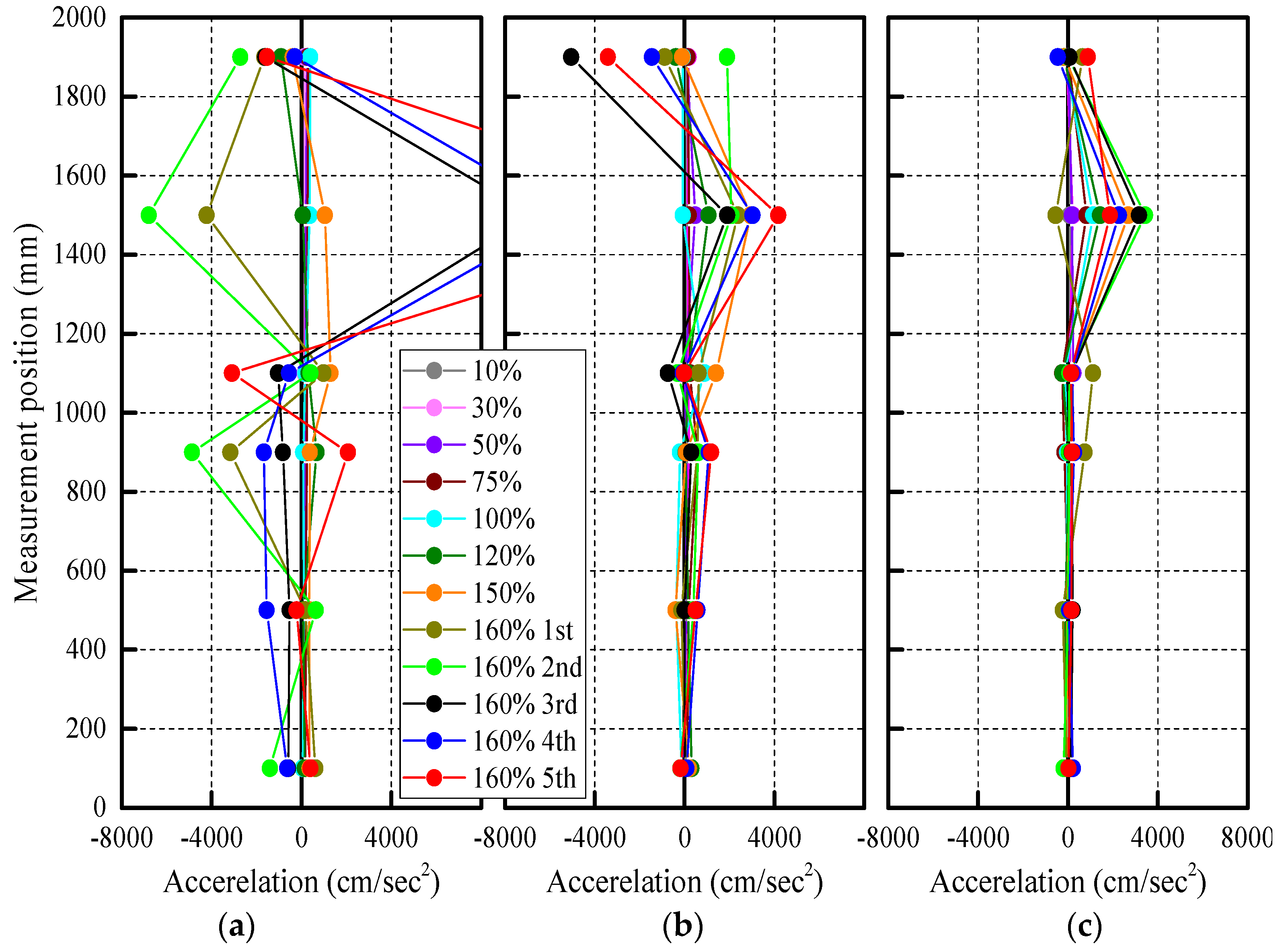
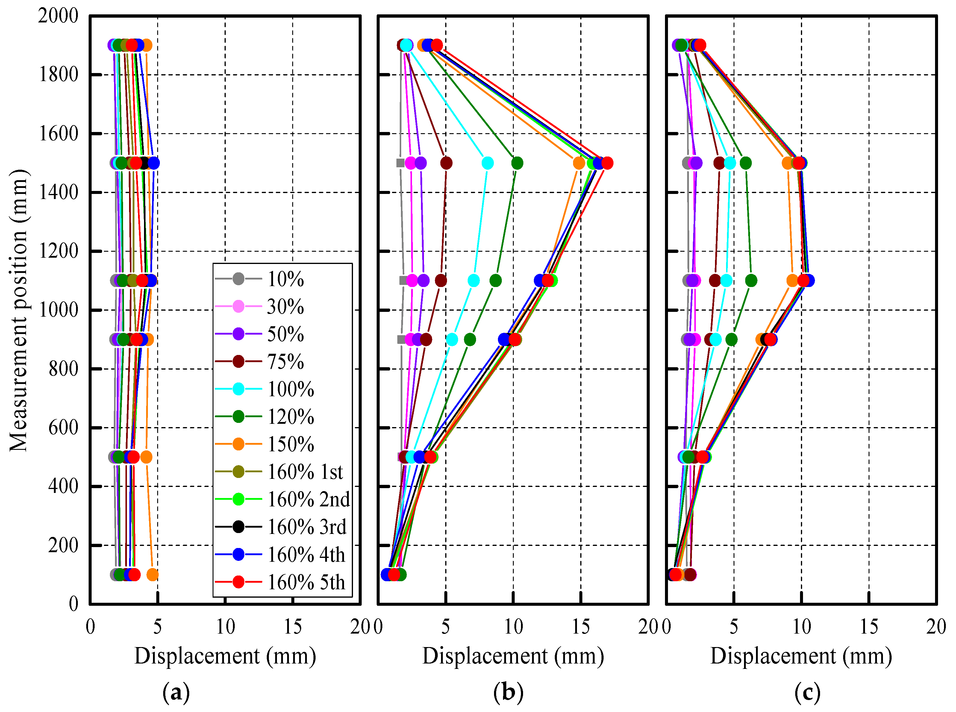
Figure 16 and Figure 17 show the acceleration and displacement profiles in each stage of each specimen when the maximum values were recorded. As shown in the figures, the acceleration and displacement values were the largest on the upper side than the center in all specimens. This result is consistent with the wall constraints; that is, the bottom of the wall is a fixed support, and the top of the wall is a roller support. In addition, due to the presence of gap in the proposed block system, Specimens HS and PS has smaller acceleration and larger displacement than Specimen CS.
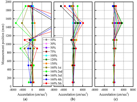
Figure 16.
Acceleration profiles: (a) Specimen CB; (b) Specimen HS; (c) Specimen PS.
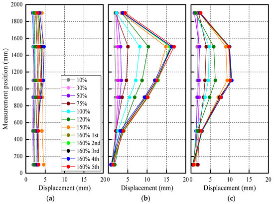
Figure 17.
Displacement profiles: (a) Specimen CB; (b) Specimen HS; (c) Specimen PS.
4. Four-Point Bending Tests
As the second experimental series, four-point bending tests were planned to evaluate the maximum tensile strength of out-of-plane direction of each specimen, since all specimens do not occur the out-of-plane collapse in the shaking table tests from the preliminary calculation. The details of the tests and results are mentioned below.
4.1. Test Specimens and Test Setup
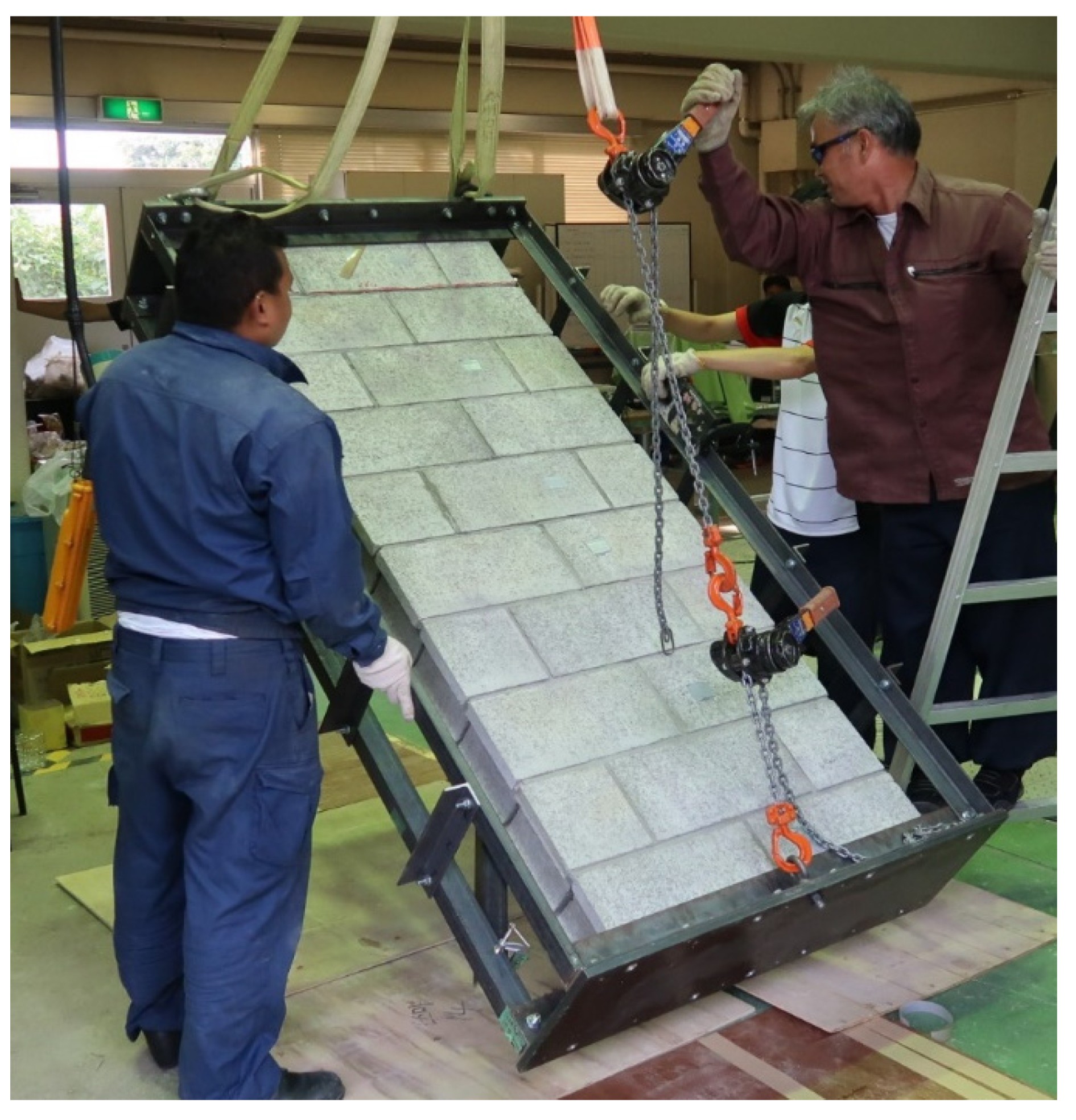
Since all specimens did not occur, the out-of-plane failure in the shaking table tests was calculated in advance; the specimens used in the shaking table tests were used in the four-point bending tests. Therefore, it is necessary to lay down each specimen to perform the four-point bending tests. Figure 18 shows the overview of laying down work. The specimen was carefully laid down, so that no force, other than self-weight of the specimen, was applied. However, Specimen CB collapsed when the inclination angle α was 21°. The force that caused the out-of-plane failure was 3.4 kN, using Equation (13).
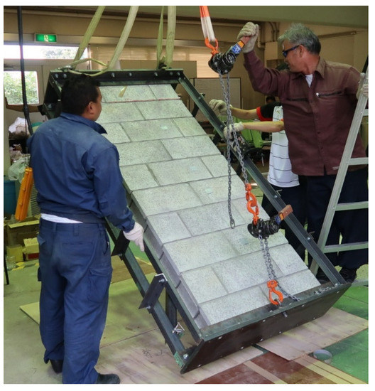
Figure 18.
Overview of laying work.
Since Specimen CB collapsed due to self-weight when it was laid down, the four-point bending tests were conducted with Specimens HS and PS. Figure 19 and Figure 20 show the conceptual drawing, including bending moment diagram of Specimen PS, and overall view of the four-point bending test, respectively.
where
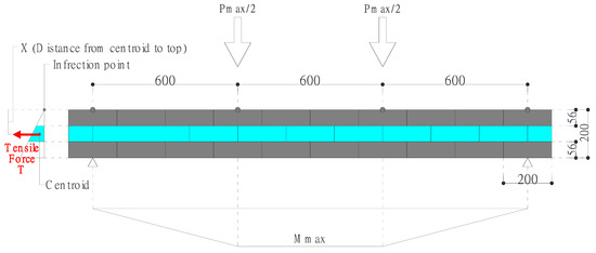
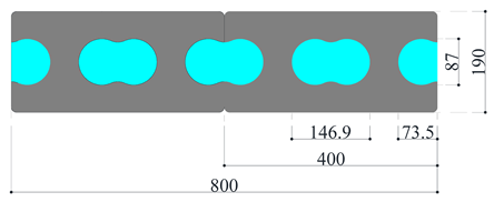
Figure 19.
Conceptual drawing of four-point bending test of Specimen PS (unit: mm).

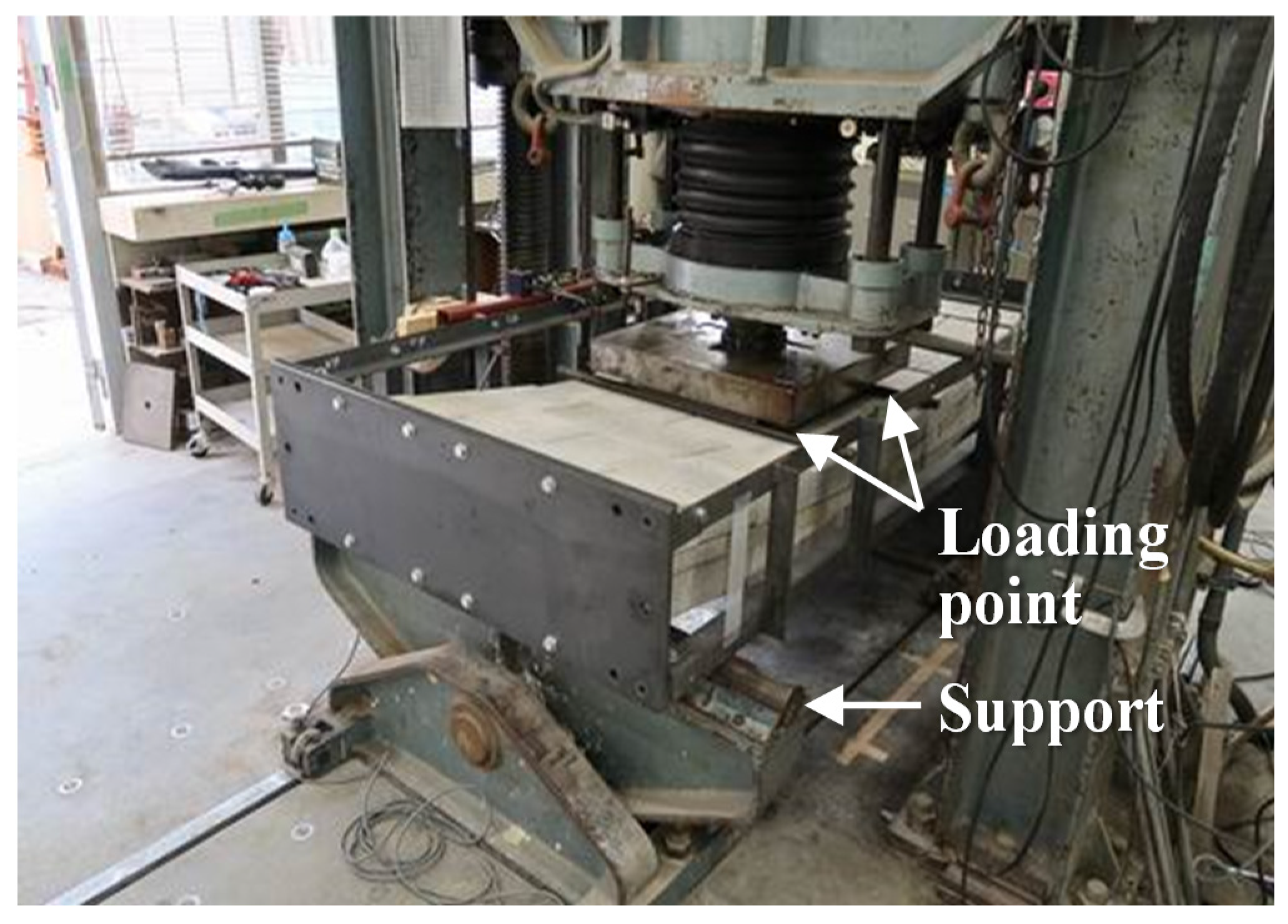
Figure 20.
Overall view of four-point bending test.
- m: Wall weight of Specimen CB (=377 kg, herein);
- g: Gravitational acceleration (=9.8 m/s2);
- α: collapsed inclination angle (=21°).
4.2. Maximum Tensile Strength of Specimens HS and PS
In this study, the maximum tensile strength by the four-point bending tests was calculated to evaluate the out-of-plane seismic capacity of the proposed block system. In calculating the maximum tensile strength, it was assumed that the center of inflection point of stress was on the upper surface of the wall and only the key block resisted, as shown in Figure 19.
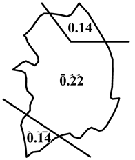
First, the maximum bending moment (Mmax) is calculated from the maximum load acting on the specimen, as shown in Figure 19. Next, the tensile stress is calculated assuming that the value of Mmax is the same as the resistance moment, due to the tensile force (T) and the distance (X) from the centroid to top, as shown in Figure 19. To simplify the calculation, the key block was replaced with two types of rectangular cross sections with the same area of H shape or peanuts shape, as shown in Table 6. In the simplification Method 1, the horizontal length of the key block was set to be the same as the horizontal length of the original key block; in the simplification Method 2, the average value of the longest and concave vertical lengths of the original key block was set as the vertical length.
Table 6.
Simplification method of cross-sectional area of key block (Specimen PS).
Table 7 shows the maximum loads and tensile strengths obtained from test results and calculation results, based on the above assumption. As shown in Table 7, the tensile stresses of the key block were almost the same, regardless of cross-section replacement methods of the key block. From the four-point bending tests, the tensile stresses of Specimen HS and PS were 0.87 to 0.89 N/mm2, which were almost the same results. Comparing the maximum loads of the proposed block system, shown in Table 7, and Specimen CS, described in Equation (13), the maximum load of Specimen CS is about 1/4 to 1/3 of that of Specimens HS and PS. This result means that the proposed block system has significantly improved seismic performance in the out-of-plane direction.
Table 7.
Maximum load and tensile stress.
5. Conclusions
The current paper presented the out-of-plane experimental tests of the two types of new concrete block walls, as well as a typical block wall, and investigated the development of predominant period, profiles of acceleration and displacement, and maximum tensile strength of each specimen. The following major findings were obtained:
- (1)
- From the shaking table test results, no extension of the predominant period was observed in all specimens, and this result was consistent with the fact that there was no noticeable damage to each specimen, until the final excitation. Since there was a gap between the main and key blocks in the proposed block system, the periods of Specimen HS and PS were longer than that of Specimen CS in all stages. The acceleration and displacement values were the largest on the upper side than the center in all specimens. This result is consistent with the wall constraints, which, at the bottom and top of the wall, were the fixed roller supports, respectively. In addition, due to the gap in the proposed block system, Specimens HS and PS had smaller acceleration and larger displacement than Specimen CS.
- (2)
- During the laying works, Specimen CB collapsed when the inclination angle was 21°, and the force that cause the out-of-plane failure was 3.4 kN.
- (3)
- From the four-point bending test results, the tensile stresses of the key block were almost the same, regardless of rectangular cross-section replacement methods of the key block. The tensile stresses of Specimen HS and PS were 0.87 to 0.89 N/mm2, which were almost the same results. Furthermore, the maximum load of Specimen CS was about 1/4 to 1/3 of that of Specimens HS and PS. This result means that the proposed block system has significantly improved seismic performance in the out-of-plane direction.
The current paper focused only on the out-of-plane experimental behavior. The experimental data should be investigated from numerical perspectives in future studies.
Author Contributions
All authors have contributed to the development of the research and in the elaboration of this article. Particularly, H.C. contributed to the methodology and experimental research, and K.-S.L. contributed the methodology and edited the manuscript. All authors have read and agreed to the published version of the manuscript.
Funding
This research received no external funding.
Acknowledgments
This research was supported by a grant (2020-MOIS31-012) from the Fundamental Technology Development program for Extreme Disaster Response, funded by Ministry of Interior and Safety (MOIS, Korea).
Conflicts of Interest
The authors declare no competing interests.
References
- Abrams, D.P.; Shah, N. Cyclic Load Testing of Unreinforced Masonry Walls; Advanced Construction Technology Centre Report No. 92-26-10; University of Illinois at Urbana Champaign: Champaign, IL, USA, 1992. [Google Scholar]
- Magenes, G.; Calvi, G.M. Shaking Table Tests on Brick Masonry Walls. In Proceedings of the 10th European Conference on Earthquake Engineering 1995, Vienna, Austria, 28 August–2 September 1994; Volume 3, pp. 2419–2424. [Google Scholar]
- Doherty, K.T. An Investigation of the Weak Links in the Seismic Load Path of Unreinforced Masonry Buildings. Ph.D. Thesis, Faculty of Engineering, University of Adelaide, Adelaide, Australia, 2000. [Google Scholar]
- Griffith, M.C.; Vaculik, J.; Lam, T.K.; Wilson, J.; Lumntarna, E. Cyclic Testing of Unreinforced Walls in Two-way Bending. Earthq. Eng. Struct. Dyn. 2006, 36, 801–821. [Google Scholar] [CrossRef]
- Simsir, C.; Aschheim, M.; Abrams, D. Influence of Diaphragm Flexibility on the Out-of-plane Response of Unreinforced Masonry Bearing Walls. In Proceedings of the 9th North American Masonry Conference 2002, Clemson, SC, USA, 1–4 June 2003. [Google Scholar]
- Tomazevic, M. Dynamic Modelling of Masonry Buildings: Storey Mechanism as a Simple Alternative. Earthq. Eng. Struct. Dyn. 1987, 15, 731–749. [Google Scholar] [CrossRef]
- Qamaruddin, M.; Chandra, B. Behaviour of Unreinforced Masonry Buildings Subjected to Earthquakes. Prof. J. Mason. Soc. USA 1991, 9, 47–55. [Google Scholar]
- Calvi, G.M.; Pavese, A. Application of Dynamic Identification Techniques to a Brick Masonry Building Prototype. In Proceedings of the 10th European Conference on Earthquake Engineering 1995, Vienna, Austria, 28 August–2 September 1994; Volume 3, pp. 2413–2418. [Google Scholar]
- Tomazevic, M. Seismic Upgrading of Old Brick-Masonry Urban Houses: Tying of Walls with Steel Ties. Earthq. Spectra 1996, 12, 599–622. [Google Scholar] [CrossRef]
- Costley, A.C.; Abrams, S.P. Dynamic Response of Unreinforced Masonry Buildings with Flexible Diaphragm; Technical Report No. MCEER-96-0001; MCEER: Buffalo, NY, USA, 1996; p. 22. [Google Scholar]
- Benedetti, D.; Carydis, P.; Pezzoli, P. Shaking Table Test on 24 Masonry Buildings. Earthq. Eng. Struct. Dyn. 1998, 27, 67–90. [Google Scholar] [CrossRef]
- Yi, T.; Moon, F.L.; Leon, R.T.; Kahn, L.F. Lateral Load Tests on a Two-story Unreinforced Masonry Building. ASCE J. Struct. Eng. 2006, 132, 643–652. [Google Scholar] [CrossRef]
- Architectural Institute of Japan (AIJ). Report on the Damage Investigation of the 1999 Chi-Chi Earthquake; AIJ: Tokyo, Japan, 2000. [Google Scholar]
- Architectural Institute of Japan (AIJ). Report on the Damage Investigation of the 2006 Central Java Earthquake; AIJ: Tokyo, Japan, 2007. [Google Scholar]
- Manafpour, A.R. Bam Earthquake, Iran: Lessons on the Seismic Behavior of Building Structures. In Proceedings of the 14th World Conference on Earthquake Engineering, Beijing, China, 12–17 October 2008. [Google Scholar]
- Sanada, Y.; Kishimoto, I.; Kuroki, M.; Sakashita, M.; Choi, H.; Tani, M.; Hosono, Y.; Fauzan, M.S.; Farida, F. Preliminary Report on Damage to Buildings due to the September 2 and 30, 2009 Earthquakes in Indonesia. In Proceedings of the Eleventh Taiwan-Korea-Japan Joint Seminar on Earthquake Engineering for Building Structures, Kyoto, Japan, 2–3 November 2009; pp. 297–306. [Google Scholar]
- Choi, H.; Sanada, Y.; Kuroki, M.; Sakashita, M.; Tani, M.; Hosono, Y.; Musalamah, S.; Farida, F. Comparing Damage to Building Structures Due to the 2009 West Java Earthquake in Indonesia. In Proceedings of the 2nd International Conference on Earthquake Engineering and Disaster Mitigation, Surabaya, Indonesia, 19 July 2011; pp. E-9–E-18. [Google Scholar]
- Architectural Institute of Japan (AIJ). Reconnaissance Report on the 2015 Nepal Gorkha Earthquake; AIJ: Tokyo, Japan, 2016. [Google Scholar]
- Akhoundi, F.; Vasconcelos, G.; Lourenco, P.; Silva, L.C. Out-of-Plane Response of Masonry Infilled RC Frames: Effect of Workmanship and Opening. In Proceedings of the 16th International Brick and Block Masonry Conference, Padova, Italy, 23 June 2016. [Google Scholar]
- Angel, R.; Abrams, D.P.; Shapiro, D.; Uzarski, J.; Webster, M. Behavior of Reinforced Concrete Frames with Masonry Infills; Department of Civil Engineering, University of Illinois at Urbana-Champaign: Champaign, IL, USA, 1994. [Google Scholar]
- Dizhur, D.; Walsh, K.; Giongo, I.; Derakhshan, H.; Ingham, J. Out-of-Plane Proof Testing of Masonry Infill Walls. Structures 2018, 15, 244–258. [Google Scholar] [CrossRef]
- Hashemi, A.; Mosalam, K.M. Shake-Table Experiment on Reinforced Concrete Structure Containing Masonry Infill Wall. Earthq. Eng. Struct. Dyn. 2006, 35, 1827–1852. [Google Scholar] [CrossRef]
- Petrone, C.; Magliulo, G.; Manfredi, G. Shake Table Tests for the Seismic Assessment of Hollow Brick Internal Partitions. Eng. Struct. 2014, 72, 203–214. [Google Scholar] [CrossRef]
- Derakhshan, H.; Dizhur, D.; Griffith, M.C.; Ingham, J.M. In Situ Out-of-Plane Testing of As-Built and Retrofitted Unreinforced Masonry Walls. J. Struct. Eng. 2014, 140, 04014022. [Google Scholar] [CrossRef] [Green Version]
- Giaretton, M.; Dizhur, D.; da Porto, F.; Ingham, J.M. Construction Details and Observed Earthquake Performance of Unreinforced Clay Brick Masonry Cavity-Walls. Structures 2016, 6, 159–169. [Google Scholar] [CrossRef]
- Damiola, M.; Esposito, R.; Messali, F.; Rots, J.G. Quasi-Static Cyclic Two-Way out-of-Plane Bending Tests and Analytical Models Comparison for URMWalls. In Proceedings of the 10th International Masonry Conference, Milan, Italy, 9–11 July 2018. [Google Scholar]
- Drysdale, R.G.; Essawy, A.S. Out-of-Plane Bending of Concrete Block Walls. J. Struct. Eng. 1988, 114, 121–133. [Google Scholar] [CrossRef]
- Gattesco, N.; Boem, I. Out-of-Plane Behavior of Reinforced MasonryWalls: Experimental and Numerical Study. Compos. Part B Eng. 2017, 128, 39–52. [Google Scholar] [CrossRef] [Green Version]
- Graziotti, F.; Tomassetti, U.; Sharma, S.; Grottoli, L.; Magenes, G. Experimental Response of URM Single Leaf and Cavity Walls in Out-of-Plane Two-Way Bending Generated by Seismic Excitation. Constr. Build. Mater. 2019, 195, 650–670. [Google Scholar] [CrossRef]
- Amin, A.; Bashar, S.M.; Fadhil, N.; Ehsan, N. Development of Interlocking Masonry Bricks and its’ Structural Behaviour: A Review Paper. IOP Conf. Ser. Earth Environ. Sci. 2018, 140, 012127. [Google Scholar]
- Hossain, M.A.; Totoev, Y.Z.; Masia, M.J. Experimental assessment of large displacement cyclic in-plane shear behaviour of semi-interlocking masonry panels. Int. J. Mason. Res. Innov. 2019, 4, 378–399. [Google Scholar] [CrossRef]
- Liu, H.; Liu, P.; Lin, K.; Zhao, S. Cyclic Behavior of Mortarless Brick Joints with Different Interlocking Shapes. Materials 2016, 3, 166. [Google Scholar] [CrossRef]
- Majid, A.; Romain, B.; Nawawi, C. Dynamic response of mortar-free interlocking structures. Constr. Build. Mater. 2013, 42, 168–189. [Google Scholar]
- Choi, H.; Lee, K.S. Experimental Study on the In-Plane Seismic Performance of a New Type of Masonry Wall System. Appl. Sci. 2020, 10, 9102. [Google Scholar] [CrossRef]
- Choi, H.; Jin, K.W.; Jeong, J.C.; Kim, B.S.; Hwang, E.J.; Jin, C. Feasibility Study on Seismic Block without Joint Mortar, Part1 Shape Determination Using Finite Element Analysis. Summaries of Technical Papers of Annual Meeting; Architectural Institute of Japan: Tokyo, Japan, 2019; Volume 4, pp. 977–978. (In Japanese) [Google Scholar]
- Architectural Institute of Korea (AIK). 2016 Korean Building Code; AIK: Seoul, Korea, 2016. (In Korean) [Google Scholar]
- Ohsaki, Y. New Introduction of Sepctral Analysis of Earthquake Ground Motion; Kajima Institute Publishing: Tokyo, Japan, 1994; pp. 81–109. (In Japanese) [Google Scholar]


Publisher’s Note: MDPI stays neutral with regard to jurisdictional claims in published maps and institutional affiliations. |
© 2021 by the authors. Licensee MDPI, Basel, Switzerland. This article is an open access article distributed under the terms and conditions of the Creative Commons Attribution (CC BY) license (https://creativecommons.org/licenses/by/4.0/).