Article

Design, Optimization and Evaluation of a New Cylinder Attachment Geometry to Improve the Hopping Height of the Bionic One-Legged Robot

School of Mechanical Engineering, Northwestern Polytechnical University, Xi’an 710072, China
*
Author to whom correspondence should be addressed.
Appl. Sci. 2021, 11(8), 3676; https://doi.org/10.3390/app11083676
Submission received: 16 March 2021 / Revised: 16 April 2021 / Accepted: 16 April 2021 / Published: 19 April 2021
(This article belongs to the Special Issue Biorobotics and Bionic Systems)

Abstract

:
Due to the high power-to-weight ratio and robustness, hydraulic cylinders are widely used in the actuation area of the legged robot systems. Most of these applications are focused on the motion stability, gait planning, and impedance control. However, the energy efficiency of the legged robotic system is also a very important point to be considered. Hopping locomotion requires a fast extension of the tibia leg at the end of the take-off phase, which causes a continuous increment of the cylinder velocity under the normally direct attachment geometry (DAG) of the cylinder. This leads to a high flow requirement, large pressure drop, and low energy efficiency. Therefore, we propose a four-bar mechanism attachment geometry (FMAG) to improve the energy efficiency by refining the relationship between the joint angle and cylinder displacement trend. The kinematic and dynamic models of the bionic one-legged robot are built to calculate the hopping process during the take-off phase. Based on the established dynamic models, the design parameters in both the DAG and FMAG are optimized to maximize the hopping height, respectively. The hopping experiments are conducted to verify the effectiveness of the new attachment geometry. The experimental results show that the robot hopping energy at the end of the take-off phase increases 14.8% under the FMAG.

1. Introduction

The legged robots have superior mobility and adaptation on the rough road compared to the wheeled and tracked robots. This significant advantage has encouraged scholars to research the legged robot over the past decades. Raibert et al. developed one-legged, biped, and quadruped running robots which performed highly dynamic ability in the 1980s [1,2,3]. All these robots used a pneumatic cylinder as a telescopic leg. The cylinder worked as an air spring that could store and recover the kinetic energy during the landing phase. Ahmadi et al. developed a one-legged hopping robot ARL-Monopod, which was driven by an electric motor. The mechanical springs located at the telescopic leg and hip joint improved this robot’s hopping efficiency [4,5].
Besides the telescopic type of the leg, the articulated leg, which could mimic the locomotion of animal, was developed and used in the bionic legged robots [6,7,8]. Lee et al. designed an articulated one-legged robot Monopod, which mimicked the segment proportion of the horse’s hindlimb [9]. Hyon et al. developed a bionic one-legged hopping robot KenKen [10,11]. Boston Dynamics designed the famous quadruped robot BigDog in 2008 [12]. This robot was able to run at about 1.6 m/s with a trotting gait and keep balancing after a strong lateral disturbance. The success of the BigDog encouraged many researchers to focus on the large quadruped robot research all over the world (e.g., HyQ [13,14], HyQ2Max [15], Scalf [16], Baby Elephant [17]). All of these quadruped robots used the double-acting hydraulic cylinder as the joint actuator due to the wide dynamic range and the high power-to-weight ratio of the cylinder.
The limbs of reptiles like lizard, alligator and gecko are laterally to the body, which cause a different locomotion posture from mammals. Alligators use sprawling posture to slide across the muddy land and erect posture to walk on the dry land [18]. To mimic the particular locomotion of alligators, Shriyam et al. developed an alligator-inspired robot [19]. Geckos have extraordinary climbing ability due to the high adhesion and friction force on their toes [20]. Kim et al. developed Stickybot to mimic the reptilian locomotion of geckos on vertical surfaces [21].
The jumping mechanisms of small animals like frog [22,23], galago [24,25], locust [26,27,28,29] and flea [30] are studied and used in the small legged robots. Due to its compactness, diversity and controllability, the electric motor is wildly used in small legged robots. Based on the hopping strategies, small-sized legged robots can be divided into two kinds. Some hop through the direct actuation of the electric motor [31,32], while the others are actuated by the catapult mechanism [33,34,35,36,37,38]. Most existed catapult mechanisms work with two stages. First, the mechanical spring stores the electric motor’s energy during the slow contraction of the leg. Then, the mechanical spring quickly releases to accelerate the robot’s body.
Due to the low power-weight ratio of the electric motor, a gear reduction device that converts the high speed into the large torque is necessary for the electric motor actuated legged robots. The gear reduction device introduces extra friction and damping and reduces the efficiency of the electric motor. The reduction gear is also easy to damage with excessive impact. Therefore, compared to the electric motor, the hydraulic cylinder is more suitable for the large legged robot.
In most hydraulic-actuated legged robots, the ends of the hydraulic cylinder always directly connect to the robot leg segments, which is named as the direct attachment geometry (DAG) in this paper. During the take-off phase, the fast extension of the tibia leads to a continuous increment of the cylinder velocity and flow requirement under the DAG. On the other side, the unavoidable pressure drop and energy consumption existing at the orifice of the control valve will deteriorate with the increment of the flow rate. Therefore, the efficiency of the hydraulic actuated legged robot is low at the hopping locomotion.
Since the relationship between the cylinder displacement and the joint angle is directly affected by the cylinder attachment geometry, the hopping performance of the legged robot could be improved by optimizing these attachment geometry parameters. Although the DAG structure is compact and simple, the number of the DAG design parameters limits the improvement of the hopping performance through parameter optimization. In this paper, a new attachment geometry of the cylinder with more design parameters is proposed. The new attachment geometry uses a four-bar mechanism to connect the cylinder rod and robot tibia, named as the four-bar mechanism attachment geometry (FMAG). A bioinspired one-legged robot that is only actuated by the knee joint cylinder and hops at the vertical rail is used to compare the performances of the DAG and FMAG. This vertical hopping model with a single actuator is wildly used in the robot field to study and test the actuator property [39,40,41,42]. The design parameters in these two attachment geometries are optimized respectively. For the accuracy of the simulation, the dynamic equations of the fluid pressure are considered during the calculation of the hopping process. The prototypes under the two attachment geometries are fabricated, and the vertical hopping experiments are conducted to verify the simulation results.
The rest of the paper is organized as follows. In Section 2, the design and parameters of the kangaroo inspired one-legged robot are described. In Section 3, the dynamic equation of the vertical hopping is given firstly, then the mathematical models of the DAG and FMAG are built, respectively. In Section 4, the constraints of the two attachment geometries are given, and the design parameters are optimized respectively to achieve their maximum hopping heights. In Section 5, two prototypes based on the two attachment geometries are fabricated. The simulation and experiment results are presented and analyzed to explore the inherent difference between the two attachment geometries. In Section 6, the conclusions and future work are discussed.

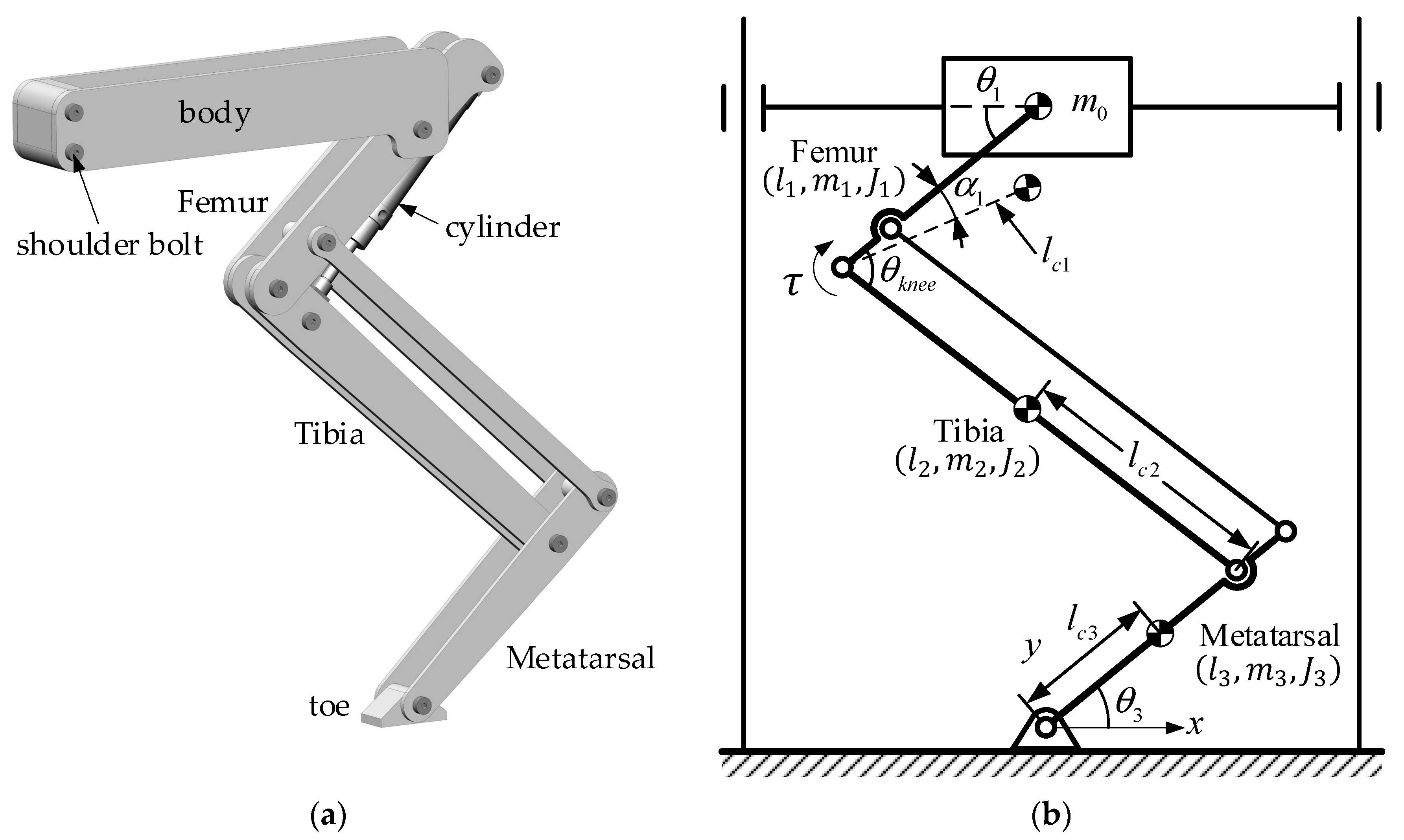
2. Kangaroo Inspired One-Legged Robot

Compared with the prismatic leg, the articulated leg has a better biomimetic characteristic by using rotating joints to mimic the knee and ankle joints of the animal. In early articulated leg structure as Bigdog, each joint in the sagittal plane was actuated by a cylinder. Although this kind of leg structure had superior kinematic flexibility, the cylinder at the ankle joint rapidly increased the leg’s inertia. Therefore, researchers proposed a compromise design that the ankle joint and knee joint were coupled by a closed chain. Based on this design principle, Sangbae Kim et al. designed a low inertia bio-inspired leg structure [43] and quadruped robot MIT Cheetah [44]. The experiment result of the MIT Cheetah has demonstrated the effectiveness and superiority of this coupled leg structure.
In this paper, a similar articulated leg is used to mimic the kangaroo’s hindlimb structure. The 3D model of this kangaroo inspired one-legged robot is shown in Figure 1a. This robot is mainly comprised of parallel plates and hydraulic cylinder. The parallel plate structure provides a robust and adequate space for the hydraulic cylinder. Moreover, plate type part can be manufactured easily by the laser cutting. The body and leg are made of 7075 aluminum alloy (8 mm thickness) because of its high strength-to-weight ratio. The high-tensile shoulder bolt (10 mm diameter) is used as the joint shaft. The needle roller bearing (BK1010) is used to decrease the friction between the revolute pairs due to its compactness and high radial load capacity. A rotational toe is used to support the robot during the take-off phase. The femur and metatarsal are parallel through a parallelogram mechanism, resulting a coupled relationship between the knee joint and ankle joint. To study the effect of the cylinder attachment geometry on the hopping height individually, the robot should only be actuated by one cylinder. Therefore, the robot body is fixed on a horizontal rack which can only slide through the vertical rail, and the one-legged robot is actuated by the cylinder installed at the knee joint. The sketch of this one-legged robot is shown in Figure 1b.
The centroid of the body is set at the horizontal rack. The centroid positions of the tibia and metatarsal are assumed to be located at the axis of each segment. The deflection angle α 1 of the centroid position of the femur is caused by the extra mass of the hydraulic cylinder. The segment proportions of this leg are set as 1:2:1, which are similar to the hindlimb proportions of the red kangaroo [45,46]. Based on the 3D model, the inertial of each leg segment relating to the corresponding joint axis has been calculated. It is worth mentioning that the inertia of the thigh is assumed to be constant for calculating the dynamic process easily in the next section. However, in reality, the inertia of the cylinder varies with the movement of the piston. Therefore, this simplified inertia model of the thigh is imperfect. On the other hand, imperfection is unavoidable in the real device [47]. Since the variation of the cylinder inertia is slight compared to the whole inertia of the thigh, this simplification is acceptable. The parameters of this one-legged robot, including sizes, mass, and inertia data, are listed in Table 1.

3. Vertical Hopping of the Kangaroo Inspired One-Legged Robot under the DAG and FMAG

3.1. Dynamic of the Vertical Hopping of the Kangaroo Inspired One-Legged Robot

Assuming there is no sliding between the toe and ground during the take-off phase and the hip joint and the toe are in the same vertical line, the hip joint and knee joint should satisfy the equation as
( l 1 + l 3 ) cos θ 1 l 2 cos ( θ k n e e θ 1 ) = 0
where θ 3 is the angle between the metatarsal and ground, while θ 1 and θ k n e e are the hip angle and knee angle.
The coordinates of each centroid of the leg and body can be expressed as
{ x 3 = l c 3 cos θ 3 y 3 = l c 3 sin θ 3 x 2 = l 3 cos θ 3 + l c 2 cos ( π θ k n e e + θ 1 ) y 2 = l 3 cos θ 3 + l c 2 sin ( π θ k n e e + θ 1 ) x 1 = l 3 cos θ 3 + l 2 cos ( π θ k n e e + θ 1 ) + l c 1 cos ( θ 1 α 1 ) y 1 = l 3 cos θ 3 + l 2 cos ( π θ k n e e + θ 1 ) + l c 1 sin ( θ 1 α 1 ) x 0 = l 3 cos θ 3 + l 2 cos ( π θ k n e e + θ 1 ) + l 1 cos ( θ 1 α 1 ) y 0 = l 3 cos θ 3 + l 2 cos ( π θ k n e e + θ 1 ) + l 1 sin ( θ 1 α 1 )
Using the Lagrange equation, the dynamic of the vertical hopping locomotion of the robot during the take-off phase can be written as
{ d d t ( L θ ˙ k n e e ) L θ k n e e = τ L = T U T = 1 2 i = 0 3 ( m i v i 2 + J i ω i 2 ) U = i = 0 3 m i g y i
where τ is the knee joint torque generated by the cylinder, T is the total kinetic energy of the robot and U is the potential energy of the robot, while m i and J i (i = 1, 2, 3) are the mass and inertia of each leg segment.

3.2. The DAG of the Cylinder

The configuration of the DAG at the knee joint is shown in Figure 2. The cylinder, femur and tibia form a triangular configuration Δ K C H 1 at the knee joint. The equivalent lever length of the cylinder as the distance between the cylinder axis and the knee joint can be expressed as
r = l K C sin θ K C H 1
where θ K C H 1 = cos 1 [ ( l K C 2 + l C H 1 2 l K H 1 2 ) / ( 2 l K C l C H 1 ) ] is the function of the cylinder length. The output torque at the knee joint generated by the cylinder can be expressed as
τ = F c y r
where F c y is the output force of the cylinder.
To decrease the inertia of the leg, the cylinder should be close to the thigh. The minimum inertia of the leg can be achieved when min h 1 = r h i p + r c y 1 + 0.0005 . h 1 is the distance between the cylinder axis and the hip joint, and can be expressed as:
{ h 1 = l H H 1 sin ( θ H H 1 K + θ K H 1 C ) l H H 1 = l K H 1 2 + l K H 2 2 l K H 1 l K H cos β 1 θ H H 1 K = cos 1 [ ( l K H 1 2 + l H H 1 2 l K H 2 ) / ( 2 l K H 1 l H H 1 ) ] θ H H 1 C = cos 1 [ ( l K H 1 2 + l C H 1 2 l K C 2 ) / ( 2 l K H 1 l C H 1 ) ]
where r h i p = 0.005   m is the radius of the hip joint axis and r c y 1 = 0.015   m is the radius of the cylinder, 0.005 is set as the safe distance to avoid the collision, l K H = l 1 is the length between the hip joint and knee joint, and l C H 1 is the length of the cylinder. When the cylinder fully retracts, the knee joint is set to 40 ° in this paper. The relationship between β 1 and β 2 can be expressed as
β 1 + β 2 = 40 ° cos 1 ( l K H 1 2 + l K C 2 l C H 1 _ m i n 2 2 l K H 1 l K C )
Therefore, l K H 1 and l K C are the independent design parameters in the DAG, β 1 and β 2 can be calculated from Equations (6) and (7).

3.3. The FMAG of the Cylinder in the Knee Joint

Although the DAG of the cylinder is compact and convenient, there are only two design parameters ( l K H 1   and l K C ) which limits the improvement of the hopping efficiency through parameter optimization. Besides the direct attachment geometry, the cylinder rod can also connect the tibia through a multi-bar linkage mechanism. Because of the diverse design parameters in the multi-bar linkage mechanism, the robot can achieve a further improvement of the hopping performance. Considering the size and complexity, we choose a four-bar mechanism in this paper.
The FMAG of the cylinder is depicted in Figure 3. Linkage AB is set as the frame of the four-bar mechanism. There are eight parameters in this FMAG as l A B , l B C , l C D , l A D , l B E , θ A B E , β 1 and β 2 . Based on the triangular configuration Δ D A E , the torque at the joint A generated by the cylinder can be expressed as
{ τ = F c y l A D sin θ A D E θ A D E = cos 1 [ ( l A D 2 + l D E 2 l A E 2 ) / ( 2 l A D l D E ) ] l A E = l A B 2 + l B E 2 2 l A B l B E cos θ A B E
Based on the vector loop of the four-bar mechanism, the relationship between θ A B C and θ E A D can be expressed as
{ θ A B C = θ A B D + θ D B C θ A B D = cos 1 l A B 2 + l B D 2 l A D 2 2 l A B l B D , θ D B C = l B D 2 + l B C 2 l C D 2 2 l B D l B C l B D = l A B 2 + l A D 2 2 l A B l A D cos ( θ B A E θ D A E ) θ B A E = cos 1 l A B 2 + l A E 2 l B E 2 2 l A B l A E , θ D A E = cos 1 l A D 2 + l A E 2 l D E 2 2 l A D l A E
Then, the output torque at the knee joint can be calculated as
τ = τ d θ A B C / d θ D A E
Combing Equations (8) and (10), the equivalent lever length of the cylinder in the FMAG can be expressed as
r = l A D sin θ A D E d θ A B C / d θ D A E
In the FMAG, l A B ,   l B C ,   l C D ,   l A D ,   l B E   and   θ A B E are the independent design parameters. The value of the angle parameter β 2 can be given as
β 2 = 40 ° min θ A B C + β 1
where β 1 is calculated from the equation as min h 1 = r h i p + r c y 1 + 0.005 . The equation of the h 1 can be expressed as
{ h 1 = l H E sin ( θ H E B + θ B E D ) l H E = l B H 2 + l B E 2 2 l B H l B E cos ( θ A B E β 1 ) θ H E B = cos 1 ( ( l H E 2 + l B E 2 l B H 2 ) / ( 2 l H E l B E ) ) θ B E D = cos 1 ( ( l B E 2 + l D E 2 l B D 2 ) / ( 2 l B E l D E ) )
where l B H = l 1 is the length between the hip joint and knee joint, l D E is the length of the cylinder.

3.4. Dynamic of the Pressures of the Cylinder

Because the hopping locomotion lasts a very short period, the flow rate of the cylinder varies largely during the take-off phase. The driving pressure and return pressure in the cylinder chambers cannot be treated as constant values. Ignoring the leakage of the cylinder, the pressure dynamics in the cylinder chambers can be written as
{ p ˙ 1 = β ε V 10 + ( l c y l c y _ m i n ) A 1 ( A 1 l ˙ c y + Q 1 ) p ˙ 2 = β ε V 20 ( l c y l c y _ m i n ) A 2 ( A 2 l ˙ c y Q 2 )
where p 1 and p 2 are the driving pressure and return pressure in the cylinder chambers, β ε is the hydraulic fluid bulk modulus, l ˙ c y is the cylinder velocity, V 10 and V 20 are the initial fluid volumes of the two chambers and hoses, A 1 and A 2 are the section areas of piston side and rod side, while Q 1 and Q 2 are the supply flow rate and return flow rate of the cylinder and can be given as
{ Q 1 = k q u p s p 1 Q 2 = k q u p 2 p T
where p s and p T are the supply pressure and the tank pressure of the hydraulic system, k q is the flow gain coefficient of the control valve, and u is the control voltage supplied to the control valve.

4. Optimization of These Two Attachment Geometries

With fixed input energy from the hydraulic system, the higher hopping height implies a more efficient hopping process of the robot. To verify the effectiveness of the FMAG, the hopping heights of the robot body under the DAG and FMAG are optimized and compared. The objective function is formulated as
H = v f i n a l 2 2 g + y 0 ( θ k n e e _ f i n a l )
where v f i n a l is the take-off speed of the robot body and θ k n e e _ f i n a l is the angle at the end of the take-off phase. The robot is set to hop from the maximum compression position, and the control valve opens from zero displacement to the maximum displacement under the maximum input voltage. Given the initial states as [ θ k n e e = 40 ° ,   θ ˙ k n e e = 0 ,   p 1 = p T ,   p 2 = p T ], the take-off phase can be simulated using the Runge–Kutta solver. The simulation process will be stopped when the ground reaction force decreases to zero. A commercial hydraulic cylinder is used in this paper. The supply pressure of the hydraulic system is set to 10   MPa. The control valve is a four-way proportional directional valve with 4 L/min flow rate at maximum valve opening and 1   MPa corresponding pressure drop. The parameters of the hydraulic system are estimated and listed in Table 2.
Before the optimization, there are some geometry constraints that should be satisfied. According to the previous literature [48,49,50], the range of the knee joint of the kangaroo is more than 100°. Therefore, the legged robot should have a similar motion range of the knee joint to mimic the motion of the kangaroo. To ensure the force transmission quality of the cylinder, the minimum transmission angle of the cylinder rod should be larger than 30°. In the DAG, the equivalent lever length r should be constrained to escape the collision between the cylinder rod and the knee joint. Thus, the constraints of the DAG are given as
{ max θ k n e e 140 ° r N r k n e e + r c y 2 + 0.005 30 ° θ K C H 1 150 °
where r N is the distance between the cylinder axis and the knee joint when the cylinder fully stretches, r k n e e = 0.005   m   and r c y 2 = 0.006   m   are the radius of the knee joint and cylinder rod, and 0.005 is set as the safe distance.
Besides the constraints of the transmission angle and the range of the knee joint, there are more geometric constraints in the FMAG. The lengths of l A B ,   l B C ,   l C D , and l A D should satisfy the motion of the four-bar mechanism. When the cylinder fully stretches, the distances between the knee joint and linkages CD and AD as h 2 N and h 3 N should be constrained to escape the collision. The distances h 4 and h 5 should also be considered to avoid the collision between joint D and the thigh and shank. Therefore, the constraints of the FMAG are given as
{ | l B C l C D | < min l B D max l B D < l B C + l C D l c y _ m a x l A D < l A E < l c y _ m i n + l A D max θ k n e e l40 ° h 2 N r k n e e + 0.5 h + 0.005 h 3 N r k n e e + 0.5 h + 0.005 min [ h 4 , h 5 ] r D + 0.5 h 1 + 0.005 30 ° θ A D E 150 °
where h = 0.02   m is the width of the links BC and CD, h 1 = 0.05   m is the width of the thigh and shank. Considering the size and compactness of the four-bar mechanism, the intervals of the six design variables are constrained as l A B , l B C , l C D , l A D [ 0.04   m , 0.08   m ] , l B E [ 0.3   m , 0.36   m ] and θ A B E [ 8 ° , 25 ° ] . Genetic Algorithm is used to complete the optimization in this paper. The optimal results of the DAG and FMAG are listed in Table 3. The maximum angles of the knee joint in the DAG and FMAG are 140 ° and 148 ° , respectively.

5. Experiment

5.1. Experimental Setup

The one-legged robot platform is built to verify the optimization results of the DAG and FMAG, as shown in Figure 4a. The frame ( 1.6   m × 1   m × 1.8   m ) is built by aluminum extrusions (6060). Two cylindrical linear rails (16 mm diameter) are fixed vertically on the frame. Four slide blocks (SBR16) are fixed symmetrically on the horizontal rack. The robot body, the horizontal rack and slide blocks weigh about 7.2 kg in total. Therefore, another 3 kg load is fixed on the rack to match the mass m 0   in Table 1. An angular transducer is installed to measure the displacement of the knee joint.
Because the landing stage is not considered in this paper, to prevent the undesired impact at the foot of the leg, the robot is locked by a locking mechanism after reaching the highest height. The locking mechanism is mainly composed of a roller chain and a single speed freewheel (20 teeth), which works as a ratchet mechanism. The close-up views of the knee joint structures of the DAG and FMAG are shown in Figure 4b,c. The structure of the rotational toe is shown in Figure 4d. To increase the friction force between the toe and ground and prevent the sliding during the take-off phase, an elastic tape with high adhesion ability is stuck at the bottom of the toe.
A fixed displacement pump with 2 ml/rev is driven by a brushless servomotor at 800 r/min. The system pressure is set as 10 MPa by the relief valve. To absorb the fluid shock and decrease the instant pressure drop, an accumulator with 0.4 L volume and 6 MPa initial pressure is added to the hydraulic system. The hydraulic circuit is shown in Figure 5. Both pressures in the cylinder two chambers are measured by the pressure transducers. The analogue signals of the knee joint angle and the fluid pressures are fed back to a computer through the data acquisition card (Advantech PCI-1716L).

5.2. Experiment Results

In this subsection, we conduct the hopping experiments to compare the hopping performance of the two attachment geometries. Figure 6 shows the images of the vertical hopping of the one-legged robot under the DAG and FMAG captured by a high-speed camera. The initial picture of the hopping locomotion is chosen when the robot leg has a slight movement. As shown in Figure 6a,b, the take-off phase of the robot under the DAG and FMAG last about 0.3 s and 0.24 s, respectively. And the corresponding hopping heights of the robot body are about 1.122 m and 1.241 m. Therefore, the FMAG can achieve a shorter takeoff time and a higher hopping height. Thanks to the high friction force of the elastic tape at the toe, there is no foot sliding during the take-off phase. The swing of the leg after the take-off phase is mainly caused by the pulling of the pipeline.
The simulation results and the experiment results of the cylinder pressures and the knee joint angles are illustrated in Figure 7. The difference between the simulation and experiment results is mainly caused by the friction force at the cylinder and vertical rail and the delay of the control valve. With the opening of the control valve, the driving pressure of the cylinders both under the DAG and FMAG quickly rise from the initial pressure, and the knee joint angle begins to accelerate from 40°. After reaching the highest pressure, the driving pressure begins to decrease continuously, and the return pressure begins to increase correspondingly. In Figure 7a, the decrease of the driving pressure accelerates gradually from about 0.04 s to 0.23 s. After that, the speed of the driving pressure decline begins to slow down from about 0.23 s to 0.32 s. In Figure 7c, the duration of the accelerated decline of the driving pressure is shorter (from about 0.035 s to 0.16 s). And the duration of the slowdown of the driving pressure decline is longer (from about 0.16 s to 0.27 s). Moreover, the final pressure drop under the DAG ( 5.4 MPa) is larger than that under the FMAG ( 4 MPa). The hopping results of the DAG and FMAG are listed in Table 4.

5.3. Discussion

To explore the intrinsic reason and find how the FMAG achieves a higher hopping height than the DAG, the experiment results combining the variation of the equivalent lever length are discussed in detail. According to the bionic leg structure in Figure 1, the angular velocity of the knee joint in this paper can be expressed as
ω k n e e = 2 v b o d y ( l 1 + l 2 + l 3 ) cos ( θ k n e e / 2 )
where v b o d y is the vertical velocity of the robot body during the take-off phase.
From Equation (19), with the increments of the knee joint angle and the body velocity, the angular velocity of the knee joint continues to increase during the take-off phase. The cylinder velocity v c y at the knee joint can be expressed as the product of the knee join angular velocity and the equivalent lever length
v c y = ω k n e e r
Based on Equation (20), the equivalent lever length can be divided into two stages. In the first stage, both of the angular velocity ω k n e e and the equivalent lever length r increase. And the speed of the increment of v c y will accelerate. In the second stage, the equivalent lever length r begins to decrease continuously. The decline of r can partially offset the increment of ω k n e e . And the speed of the increment of v c y will slow down gradually. Based on the upper optimization results, the equivalent lever lengths of the DAG and FMAG are shown in Figure 8a. The first stage in the DAG accounts for 38.4% of the range of the knee joint, while it is only 16.6% in the FMAG. Moreover, in the second stage, the variation of the equivalent lever length of the FMAG (from 0.0479 m to 0.0171 m) is larger than that of the DAG (from 0.0462 m to 0.0251 m).
The experiment results of the cylinder velocity and the corresponding equivalent lever length of the DAG and FMAG are shown in Figure 8b,c. The larger initial equivalent lever length under the FMAG causes a quicker increment of the cylinder velocity at the beginning. Benefitting from the low percentage of the first stage, the increment of the cylinder velocity under the FMAG begins to slow down (at about 0.16 s and 0.3 m/s) earlier than that under the DAG (at about 0.23 s and 0.36 m/s). With the decrease of the equivalent lever length, the speed of the cylinder velocity increment decreases continuously. The cylinder velocities both under the DAG and FMAG almost maintain constant at the end of the take-off stage. Due to the larger proportion of the second stage of the equivalent lever length, the final cylinder velocity under the FMAG (0.43 m/s) is smaller than that of the DAG (0.49 m/s). Therefore, the pressure drop under the FMAG is smaller than that under the DAG. And more energy is supplied to the cylinder, resulting in a higher hopping height of the robot body under the FMAG. The robot hopping energy as the sum of the kinetic and potential energy increment is shown in Figure 8d. The final hopping energy under the FMAG (about 93 J) is larger than that of the DAG (about 81 J). Thus, the robot can receive 14.8% more energy under the FMAG.

6. Conclusions

The high energy consumption and low efficiency of the hydraulic actuated legged robot during the hopping locomotion are still severe problems at present. One reason for this is the large pressure drop at the control value when the robot requires a high flow rate. This is mainly caused by the traditional attachment geometry between the cylinder and the leg segments. To improve the hopping height of the legged robot, this paper presents a new attachment geometry FMAG to replace the traditional attachment geometry DAG. The FMAG brings six design parameters to modify the relationship between the joint angle and the cylinder displacement, while the DAG only has two design parameters. Based on the dynamic model of the vertical hopping, these design parameters in the two attachment geometries are optimized to maximize the corresponding hopping height. Prototypes are fabricated with these optimized parameters. The simulation and experiment results verify the effectiveness of the FMAG. With a 10 MPa supply pressure from the hydraulic system, the hopping height of the robot body under the FMAG is about 0.12 m higher than that under the DAG.
The intrinsic difference between the DAG and FMAG is the relationship between the equivalent lever length and the joint angle. Compared with the DAG, the FMAG has a larger range of the equivalent lever length and a larger proportion of the descent stage of the equivalent lever length. These properties of the FMAG can offset the increase of the joint angular velocity and slow down the driving pressure drop better at the end of the take-off phase. In further research, another hydraulic cylinder will be added to the hip joint, making the prototype a fully actuated one-legged robot. The control strategy for the continuous hopping of the robot with the FMAG in the knee joint will be studied.

Author Contributions

Conceptualization, D.Z.; software, D.Z. and X.M.; validation, D.Z., X.M., and Z.W.; writing—original draft preparation, D.Z.; writing—review and editing, W.G., X.M., Y.L., and Z.W.; visualization, D.Z. and Y.L.; supervision, W.G.; project administration, W.G. All authors have read and agreed to the published version of the manuscript.

Funding

This research was funded by National Key Research and Development Program of China, grant number (2017YFB1300101), National Natural Science Foundation of China (51375383) and Research Fund for the Doctoral Program of Higher Education of China (20136102130001).

Institutional Review Board Statement

Not applicable.

Informed Consent Statement

Not applicable.

Data Availability Statement

Not applicable.

Conflicts of Interest

The authors declare no conflict of interest. The funders had no role in the design of the study; in the collection, analyses, or interpretation of data; in the writing of the manuscript, or in the decision to publish the results.

References

  1. Raibert, M.H.; Brown, H.B. Experiments in Balance with a 2D One-Legged Hopping Machine. J. Dyn. Syst. Meas. Control Trans. ASME 1984, 106, 75–81. [Google Scholar] [CrossRef]
  2. Hodgins, J.K.; Raibert, M.H. Biped gymnastics. Artif. Intell. MIT 1990, 9, 115–128. [Google Scholar] [CrossRef]
  3. Raibert, M.H.; Tello, E.R. Legged Robots That Balance; MIT Press: Cambridge, MA, USA, 1986. [Google Scholar]
  4. Gregorio, P.; Ahmadi, M.; Buehler, M. Design, control, and energetics of an electrically actuated legged robot. IEEE Trans. Syst. Man Cybern. Syst. 1997, 27, 626–634. [Google Scholar] [CrossRef]
  5. Ahmadi, M.; Buehler, M. Stable control of a simulated one-legged running robot with hip and leg compliance. In Proceedings of the International Conference on Robotics and Automation, Albuquerque, NM, USA, 21–27 April 1997; pp. 96–104. [Google Scholar]
  6. Zhou, X.; Bi, S. A survey of bio-inspired compliant legged robot designs. Bioinspir. Biomim. 2012, 7, 41001. [Google Scholar] [CrossRef]
  7. Zhang, Z.; Zhao, J.; Chen, H.; Chen, D. A Survey of Bioinspired Jumping Robot: Takeoff, Air Posture Adjustment, and Landing Buffer. Appl. Bionics Biomech. 2017, 2017, 1–22. [Google Scholar] [CrossRef] [Green Version]
  8. Mo, X.; Ge, W.; Miraglia, M.; Inglese, F.; Zhao, D.; Stefanini, C.; Romano, D. Jumping Locomotion Strategies: From Animals to Bioinspired Robots. Appl. Sci. 2020, 10, 8607. [Google Scholar] [CrossRef]
  9. Lee, W.; Raibert, M. Control of hoof rolling in an articulated leg. In Proceedings of the IEEE International Conference on Robotics and Automation, Sacramento, CA, USA, 9–11 April 1991; pp. 1386–1391. [Google Scholar]
  10. Hyon, S.H.; Mita, T. Development of a biologically inspired hopping robot-“Kenken”. In Proceedings of the 2002 IEEE International Conference on Robotics and Automation, Washington DC, USA, 10–17 May 2002; pp. 3984–3991. [Google Scholar]
  11. Hyon, S.H.; Emura, T.; Mita, T. Dynamics-based control of a one-legged hopping robot. Proc. Inst. Mech. Eng. Part I J. Syst. Control Eng. 2003, 217, 83–98. [Google Scholar] [CrossRef]
  12. Raibert, M.; Blankespoor, K.; Nelson, G.; Playter, R. BigDog, the Rough-Terrain Quadruped Robot. In Proceedings of the 17th World Congress the International Federation of Automatic Control, Seoul, Korea, 6–11 July 2008; pp. 10822–10825. [Google Scholar]
  13. Semini, C.; Tsagarakis, N.G.; Vanderborght, B.; Yang, Y.; Caldwell, D.G. HyQ—Hydraulically actuated quadruped robot: Hopping leg prototype. In Proceedings of the International Conference on Biomedical Robotics and Biomechatronics, Scottsdale, AZ, USA, 19–22 October 2008; pp. 593–599. [Google Scholar]
  14. Semini, C.; Tsagarakis, N.G.; Guglielmino, E.; Focchi, M.; Cannella, F.; Caldwell, D.G. Design of HyQ—A hydraulically and electrically actuated quadruped robot. Proc. Inst. Mech. Eng. Part I J. Syst. Control Eng. 2011, 225, 831–849. [Google Scholar] [CrossRef]
  15. Semini, C.; Barasuol, V.; Goldsmith, J.; Frigerio, M.; Focchi, M.; Gao, Y.; Caldwell, D.G. Design of the Hydraulically Actuated, Torque-Controlled Quadruped Robot HyQ2Max. IEEE ASME Trans. Mechatron. 2017, 22, 635–646. [Google Scholar] [CrossRef]
  16. Rong, X.; Li, Y.; Ruan, J.; Li, B. Design and simulation for a hydraulic actuated quadruped robot. J. Mech. Sci. Technol. 2012, 26, 1171–1177. [Google Scholar] [CrossRef]
  17. Chen, X.; Gao, F.; Qi, C.; Tian, X.; Zhang, J. Spring Parameters Design for the New Hydraulic Actuated Quadruped Robot. J. Mech. Robot. 2014, 6, 21003. [Google Scholar] [CrossRef]
  18. Reilly, S.M.; Elias, J.A. Locomotion in Alligator Mississippiensis: Kinematic Effects of Speed and Posture and Their Relevance to the Sprawling-To-Erect Paradigm. J. Exp. Biol. 1998, 201, 2559–2574. [Google Scholar]
  19. Shriyam, S.; Mishra, A.; Nayak, D.; Thakur, A. Design, fabrication, and gait planning of alligator-inspired robot. Int. J. Curr. Eng. Technol. 2014, 2, 567–575. [Google Scholar] [CrossRef]
  20. Tian, Y.; Pesika, N.; Zeng, H.; Rosenberg, K.; Zhao, B.; McGuiggan, P.; Autumn, K.; Israelachvili, J.N. Adhesion and friction in gecko toe attachment and detachment. Proc. Natl. Acad. Sci. USA 2006, 103, 19320–19325. [Google Scholar] [CrossRef] [Green Version]
  21. Kim, S.; Spenko, M.; Trujillo, S.; Heyneman, B.; Santos, D.; Cutkosky, M.R. Smooth Vertical Surface Climbing with Directional Adhesion. IEEE Trans. Robot. 2008, 24, 65–74. [Google Scholar]
  22. Astley, H.C.; Roberts, T.J. Evidence for a vertebrate catapult: Elastic energy storage in the plantaris tendon during frog jumping. Biol. Lett. 2012, 8, 386–389. [Google Scholar] [CrossRef] [Green Version]
  23. Azizi, E.; Roberts, T.J. Muscle performance during frog jumping: Influence of elasticity on muscle operating lengths. Proc. R. Soc. B Biol. Sci. 2010, 277, 1523–1530. [Google Scholar] [CrossRef] [Green Version]
  24. Wang, M.; Zang, X.Z.; Fan, J.Z.; Zhao, J. Biological jumping mechanism analysis and modeling for frog robot. J. Bionic Eng. 2008, 5, 181–188. [Google Scholar] [CrossRef]
  25. Aerts, P. Vertical jumping in Galago senegalensis: The quest for an obligate mechanical power amplifier. Philos. Trans. R. Soc. Lond. B Biol. Sci. 1998, 353, 1607–1620. [Google Scholar] [CrossRef] [Green Version]
  26. Mo, X.; Romano, D.; Miraglia, M.; Ge, W.; Stefanini, C. Effect of Substrates’ Compliance on the Jumping Mechanism of Locusta migratoria. Front. Bioeng. Biotechnol. 2020, 8, 661. [Google Scholar] [CrossRef]
  27. Romano, D.; Bloemberg, J.; Tannous, M.; Stefanini, C. Impact of Aging and Cognitive Mechanisms on High-Speed Motor Activation Patterns: Evidence from an Orthoptera-Robot Interaction. IEEE Trans. Med. Robot. Bionics 2020, 2, 292–296. [Google Scholar] [CrossRef]
  28. Romano, D.; Benelli, G.; Stefanini, C. Encoding lateralization of jump kinematics and eye use in a locust via bio-robotic artifacts. J. Exp. Biol. 2019, 222, jeb187427. [Google Scholar] [CrossRef] [Green Version]
  29. Romano, D.; Benelli, G.; Stefanini, C. Escape and surveillance asymmetries in locusts exposed to a Guinea fowl-mimicking robot predator. Sci. Rep. 2017, 7, 12825. [Google Scholar] [CrossRef] [Green Version]
  30. Sutton, G.P.; Burrows, M. Biomechanics of jumping in the flea. J. Exp. Biol. 2011, 214, 836–847. [Google Scholar] [CrossRef] [PubMed] [Green Version]
  31. Haldane, D.W.; Plecnik, M.M.; Yim, J.K.; Fearing, R.S. Robotic vertical jumping agility via series-elastic power modulation. Sci. Robot. 2016, 1, eaag2048. [Google Scholar] [CrossRef] [Green Version]
  32. Plecnik, M.M.; Haldane, D.W.; Yim, J.K.; Fearing, R.S. Design exploration and kinematic tuning of a power modulating jumping monopod. J. Mech. Robot. 2017, 9, 011009. [Google Scholar] [CrossRef]
  33. Noh, M.; Kim, S.W.; An, S.; Koh, J.S.; Cho, K.J. Flea-inspired catapult mechanism for miniature jumping robots. IEEE Trans. Robot. 2012, 28, 1007–1018. [Google Scholar]
  34. Kovac, M.; Fuchs, M.; Guignard, A.; Zufferey, J.C.; Floreano, D. A miniature 7 g jumping robot. In Proceedings of the 2008 IEEE International Conference on Robotics and Automation, Pasadena, CA, USA, 19–23 May 2008; pp. 373–378. [Google Scholar]
  35. Chen, D.; Yin, J.; Zhao, K.; Zheng, W.; Wang, T. Bionic mechanism and kinematics analysis of hopping robot inspired by locust jumping. J. Bionic Eng. 2011, 8, 429–439. [Google Scholar] [CrossRef]
  36. Zhang, J.; Song, G.; Li, Y.; Qiao, G.; Song, A.; Wang, A. A bio-inspired jumping robot: Modeling, simulation, design, and experimental results. Mechatronics 2013, 23, 1123–1140. [Google Scholar] [CrossRef]
  37. Zhang, Z.; Yang, Q.; Gui, S.; Chang, B.; Zhao, J.; Yang, H.; Chen, D. Mechanism design for locust-inspired robot with one-DOF leg based on jumping stability. Mech. Mach. Theory 2019, 133, 584–605. [Google Scholar] [CrossRef]
  38. Koh, J.S.; Jung, S.P.; Noh, M.; Kim, S.W.; Cho, K.J. Flea inspired catapult mechanism with active energy storage and release for small scale jumping robot. In Proceedings of the 2013 IEEE International Conference on Robotics and Automation, Karlsruhe, Germany, 6–10 May 2013; pp. 26–31. [Google Scholar]
  39. Curran, S.; Knox, B.T.; Schmiedeler, J.P.; Orin, D.E. Design of Series-Elastic Actuators for Dynamic Robots with Articulated Legs. J. Mech. Robot. 2009, 1, 11006. [Google Scholar] [CrossRef]
  40. Vanderborght, B.; Tsagarakis, N.G.; Ham, R.; Thorson, I.; Caldwell, D.G. MACCEPA 2.0: Compliant actuator used for energy efficient hopping robot Chobino1D. Auton. Robot. 2011, 31, 55–65. [Google Scholar] [CrossRef]
  41. Okada, M.; Takeda, Y. Optimal design of nonlinear profile of gear ratio using non-circular gear for jumping robot. In Proceedings of the 2012 IEEE International Conference on Robotics and Automation, Saint Paul, MN, USA, 14–18 May 2012; pp. 1958–1963. [Google Scholar]
  42. Verstraten, T.; Furnemont, R.; Beckerle, P.; Vanderborght, B.; Lefeber, D. A Hopping Robot Driven by a Series Elastic Dual-Motor Actuator. IEEE Robot. Autom. Lett. 2019, 4, 2310–2316. [Google Scholar] [CrossRef]
  43. Ananthanarayanan, A.; Azadi, M.; Kim, S. Towards a bio-inspired leg design for high-speed running. Bioinspir. Biomim. 2012, 7, 46005. [Google Scholar] [CrossRef]
  44. Seok, S.O.; Wang, A.D.; Chuah, M.Y.; Hyun, D.J.; Lee, J.; Otten, D.M.; Lang, J.H.; Kim, S. Design Principles for Energy-Efficient Legged Locomotion and Implementation on the MIT Cheetah Robot. IEEE ASME Trans. Mechatron. 2015, 20, 1117–1129. [Google Scholar] [CrossRef] [Green Version]
  45. McGowan, C.P.; Skinner, J.; Biewener, A.A. Hind limb scaling of kangaroos and wallabies (superfamily Macropodoidea): Implications for hopping performance, safety factor and elastic savings. J. Anat. 2008, 212, 153–163. [Google Scholar] [CrossRef] [PubMed]
  46. Kear, B.P.; Lee, M.S.Y.; Gerdtz, W.R.; Flannery, T.F. Evolution of hind limb proportions in kangaroos (Marsupialia: Macropodoidea). In Mammalian Evolutionary Morphology. Vertebrate Paleobiology and Paleoanthropology Series; Sargis, E.J., Dagosto, M., Eds.; Springer: Dordrecht, The Netherlands, 2008; pp. 25–35. [Google Scholar]
  47. Bucolo, M.; Buscarino, A.; Famoso, C.; Fortuna, L.; Frasca, M. Control of imperfect dynamical systems. Nonlinear Dyn. 2019, 98, 2989–2999. [Google Scholar] [CrossRef]
  48. Dawson, R.S.; Warburton, N.M.; Richards, H.L.; Milne, N. Walking on five legs: Investigating tail use during slow gait in kangaroos and wallabies. Aust. J. Zool. 2015, 63, 192–200. [Google Scholar] [CrossRef]
  49. McGowan, C.P.; Baudinette, R.V.; Biewener, A.A. Modulation of proximal muscle function during level versus incline hopping in tammar wallabies (Macropus eugenii). J. Exp. Biol. 2007, 210, 1255–1265. [Google Scholar] [CrossRef] [Green Version]
  50. Biewener, A.A.; McGowan, C.; Card, G.M.; Baudinette, R.V. Dynamics of leg muscle function in tammar wallabies (M. eugenii) during level versus incline hopping. J. Exp. Biol. 2004, 207, 211–223. [Google Scholar] [CrossRef] [Green Version]
Figure 1. Kangaroo inspired one-legged robot. (a) 3D model, (b) Sketch of the robot.
Applsci 11 03676 g001
Figure 2. The DAG of the cylinder at the knee joint.
Applsci 11 03676 g002
Figure 3. The FMAG of the cylinder at the knee joint.
Applsci 11 03676 g003
Figure 4. One-legged vertical hopping robot platform. (a) Prototype of the one-legged robot and the test platform; (b) Close-up view of the DAG; (c) Close-up view of the FMAG; (d) Close-up view of the toe.
Applsci 11 03676 g004
Figure 5. Hydraulic and test system. (a) Sketch of the hydraulic system; (b) Physical layout of the hydraulic and test system.
Applsci 11 03676 g005
Figure 6. Images of hopping locomotion under the two attachment geometries recorded at 100 fps. (a) Hopping locomotion under the DAG; (b) Hopping locomotion under the FMAG.
Applsci 11 03676 g006
Figure 7. Simulation and experiment results of the cylinder pressures and knee joints under the DAG and FMAG. (a) Cylinder pressures of the DAG; (b) Knee joint angle of the DAG; (c) Cylinder pressures of the FMAG; (d) Knee joint angle of the FMAG.
Applsci 11 03676 g007
Figure 8. Analysis of the experiment results. (a) Relationship between the knee joint angle and the equivalent lever length; (b) Cylinder velocity and the corresponding equivalent lever length under the DAG; (c) Cylinder velocity and the corresponding equivalent lever length under the FMAG; (d) Robot hopping energy under the DAG and FMAG.
Applsci 11 03676 g008aApplsci 11 03676 g008b
Table 1. Parameters of the kangaroo inspired one-legged robot.
ParametersValueParametersValue
l 1 (m)0.2 J 2 (kgm2)0.05
m 1 (kg)1.72 l c 2 (m)0.26
J 1 (kgm2)0.0631 l 3 (m)0.2
l c 1 (m)0.174 m 3 (kg)0.52
α 1 (°)5 J 3 (kgm2)0.0131
l 2 (m)0.4 l c 3 (m)0.12
m 2 (kg)0.908 m 0 (kg)10
Table 2. Parameters of the hydraulic system.
ParametersValueParametersValue
β ε (MPa) 700 l c y _ m i n (m)0.256
V 10 (m3) 4.2 × 10 5 cylinder stroke (m)0.07
V 20 (m3) 5 × 10 5 A 1 (m2) 3.14 × 10 4
k q ( m 3 / ( sV MPa ) ) 6.64 × 10 6 A 2 (m2) 2.01 × 10 4
Table 3. Optimized results of the design parameters in the DAG and FMAG.
Optimized Design Parameters
DAG a 1 = 0.2883   m ,   a 2 = 0.0462   m ,   β 1 = 4.8 ° ,   β 2 = 7 °
FMAG l A B = 0.0665   m , l B C = 0.0468   m , l C D = 0.0819   m , l A D = 0.0627   m ,
l B E = 0.3538   m , θ A B E = 15.15 ° , β 1 = 12.2 ° , β 2 = 29.56 °
Table 4. Hopping results of the kangaroo inspired one-legged robot.
Maximum Hopping HeightTake-Off SpeedTake-Off DurationMaximum Pressure Drop
DAG1.122 m2.69 m/s0.32 s5.4 MPa
FMAG1.241 m3.04 m/s0.27 s4 MPa
Publisher’s Note: MDPI stays neutral with regard to jurisdictional claims in published maps and institutional affiliations.

