Article

A Circular Sector-Shaped Dipole Antenna with Meandered Arms and Added Ferrite-Loaded Artificial Magnetic Conductor

Department of Electrical and Computer Engineering, Sungkyunkwan University, Suwon 16419, Korea
*
Author to whom correspondence should be addressed.
Appl. Sci. 2022, 12(18), 9149; https://doi.org/10.3390/app12189149
Submission received: 25 July 2022 / Revised: 25 August 2022 / Accepted: 7 September 2022 / Published: 13 September 2022
(This article belongs to the Section Electrical, Electronics and Communications Engineering)

Abstract

:
A circular sector-shaped dipole antenna with meandered arms based on an artificial magnetic conductor (AMC) is proposed in this study. A compact unit cell of the AMC operating within 19–485 MHz is designed using a ferrite material, which exhibits high-permeability characteristics in the high-frequency (HF), very-high-frequency (VHF), and ultra-high-frequency (UHF) bands. The configuration of the meandered arms is optimally designed using a binary genetic algorithm, so that the antenna combined with the AMC meets the voltage standing wave ratio (VSWR) specification of 3.5:1 or less within the HF, VHF, and UHF bands. The proposed antenna with the AMC is fabricated and measured. The measured VSWR frequency bandwidth (3.5:1 or less) is 25.8:1 (14–361 MHz), and the measured result matches with the simulated result well. Furthermore, to verify the performance of the proposed antenna with the AMC, the measured received power results are compared with a commercial reference antenna operating in HF, VHF, and UHF bands.

1. Introduction

The high-frequency (HF), very-high-frequency (VHF), and ultra-high-frequency (UHF) band antennas used in military and disaster control fields have a relatively long electrical wavelength, making the size of the antenna inevitably large [1]. Thus, it is unsuitable to mount an antenna operating in HF, VHF, and UHF bands on an application, such as a ground vehicle, which is smaller than the wavelength of the operating frequency. Consequently, a study on electrically small antennas (ESAs) operating in HF, VHF, and UHF bands has been conducted [2,3,4,5,6]. Although the proposed antennas are miniaturized enough to be mounted on a ground vehicle, they have narrow operating bandwidth characteristics because of the high Q value of the ESA [7]. Several methods have been studied to improve the operating bandwidth of the ESA [8,9,10,11,12,13,14,15]. In the studies [8,9,10,11,12,13], the antenna broadens the operating bandwidth by adding a multi-near-field resonant parasitic element. However, in the studies [14,15], the active non-Foster circuit is used to widen the operating bandwidth of the antenna.
The artificial magnetic conductor (AMC), which is composed of a periodic unit cell structure, can enhance the operating bandwidth of the antenna because of the mutual coupling between the antenna and the AMC, and it is also possible to miniaturize the antenna [16]. Furthermore, when an AMC is used as a reflector, the image current on its surface is formed in an identical direction as that of the antenna, and the phase of the incident and reflected waves are also identical; thus, the low-profile characteristics of the antenna can be achieved [17,18]. Miniaturized antennas have been proposed in the HF, VHF and UHF bands using the characteristics of the AMC [19,20,21].
A circular sector-shaped dipole antenna with meandered arms based on an AMC is proposed in this study. A unit cell structure is designed by applying a ferrite material [20] with high permeability in the HF, VHF, and UHF bands to design a compact and broadband AMC for application to an antenna. The operating frequency bandwidth of the artificial magnetic conductor is proportional to the equivalent inductance [22]. In order to increase the equivalent inductance, ferrite with a high permeability value was used as a substrate. Each element of the dipole antenna has a shape combined with the meandered arms symmetrically, which are located up and down around the circular sector-shaped antenna. The configuration of the meandered arm was optimally designed using a binary genetic algorithm, so that the antenna satisfies the VSWR characteristics of 3.5:1 or less in the HF, VHF, and UHF bands. Compared with the previous studies [19,20], the size and operating bandwidth characteristics are improved from those of the study [19], and it operates at the lowest operating frequency, lower than the antenna of the study [20]. All the simulations in this study were conducted using the CST software. The AMC and antenna designs are described in Section 2. In Section 3, the simulation and measurement results of the designed antenna are presented. Section 4 compares the performance of the designed antenna and the commercial antenna. Finally, this paper ends in Section 5.

2. The AMC and Antenna Designs

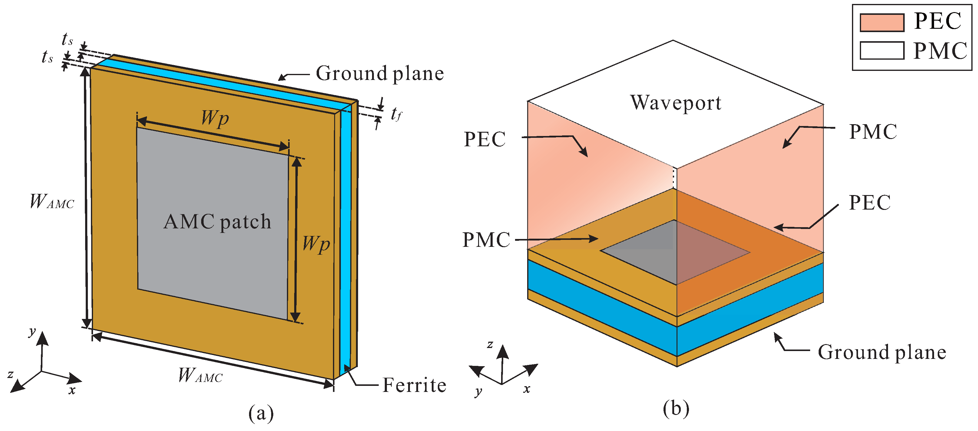
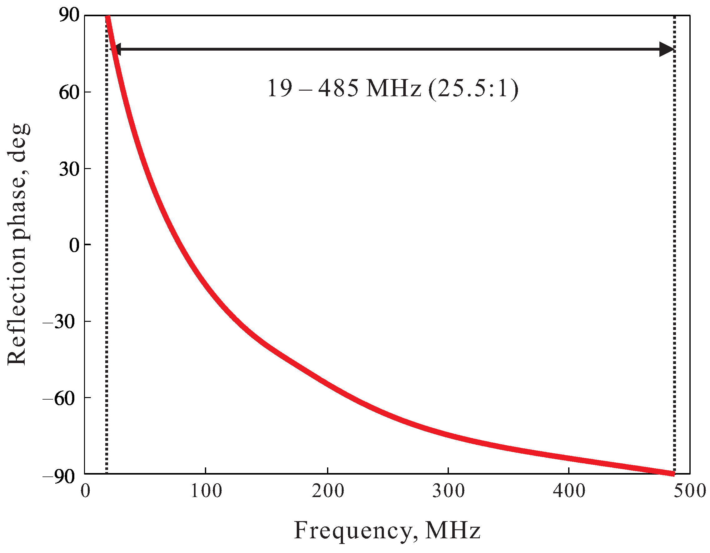
2.1. Design of AMC Structure

Figure 1 depicts the configurations of the designed unit cell of the AMC. The AMC unit cell is composed of two FR-4 substrates (a material with a dielectric constant of 4.3, loss tangent of 0.025, and thickness of 1.52 mm), and a ferrite material called MP2106-0M0, made by Laird [23]. The ferrite material has high-permeability properties in the HF, VHF, and UHF bands. It is positioned between the two FR-4 substrates (Figure 1a) and the thickness is t f = 10 mm. The upper side of the upper substrate has a patch and the lower side of the lower substrate has a ground area. The side length of the unit cell and square patch are W A M C = 100 mm, and W P = 60 mm, respectively.
Figure 1b shows the simulation boundary condition of the unit cell. To set up the periodic boundary condition, the planes on the x and y-axis are designated as perfect electric conductor (PEC) and perfect magnetic conductor (PMC), respectively. To simulate the reflection phase of the unit cell, the waveport is located on the +z-axis.
Figure 2 illustrates the simulated reflection phase of the designed unit cell. The unit cell’s operating bandwidth is generally referred to as a frequency range with the reflection phase characteristics ranging from 90 to +90 [24]. The simulated operating frequency range of the unit cell is 19–485 MHz (25.5:1). The simulation results show that a compact broadband unit cell is designed using high-permeability ferrite material. In order to verify the performance of the designed AMC unit cell, the performance was compared with existing studies. The operating bandwidth and size of the designed AMC are specified in Table 1.

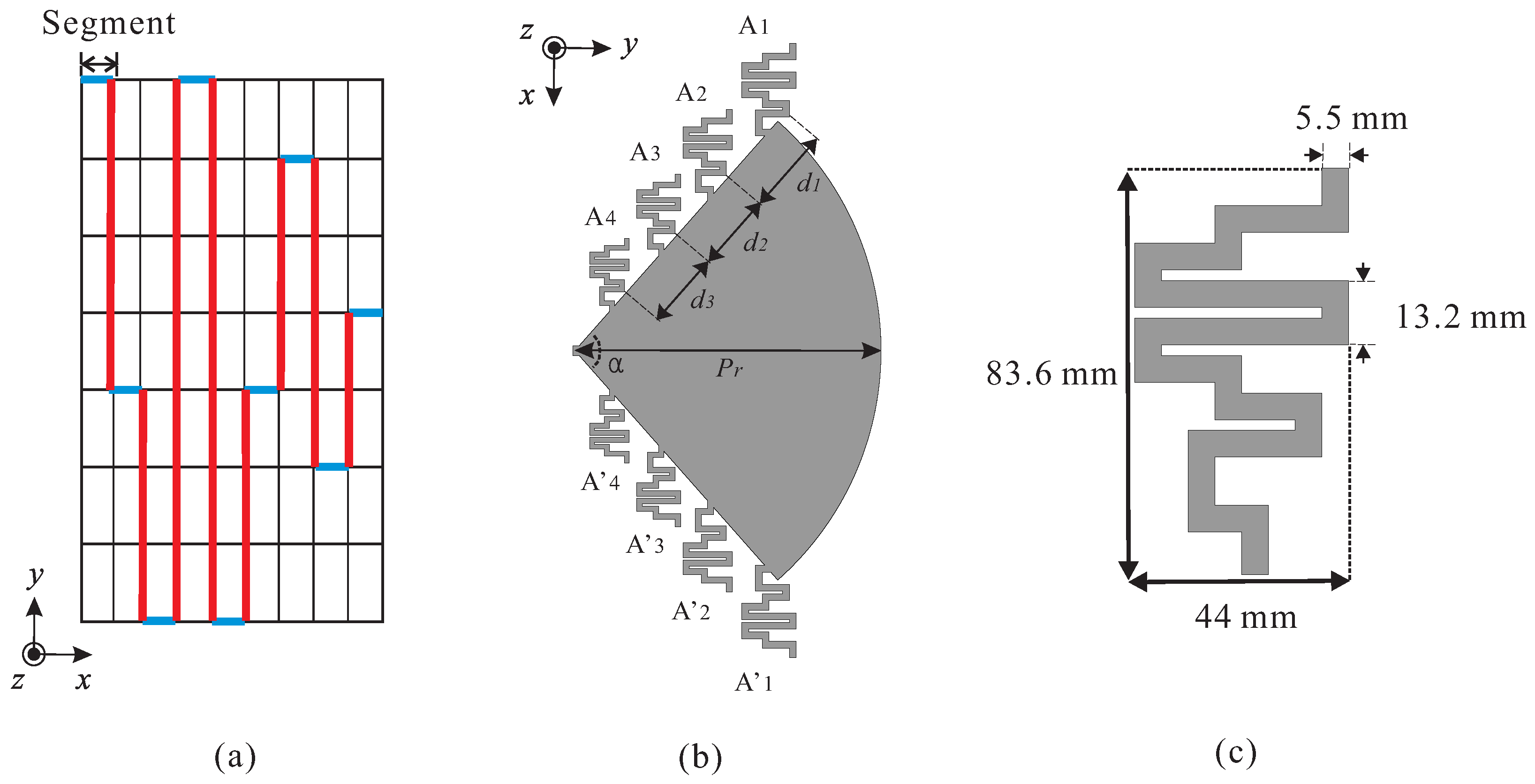
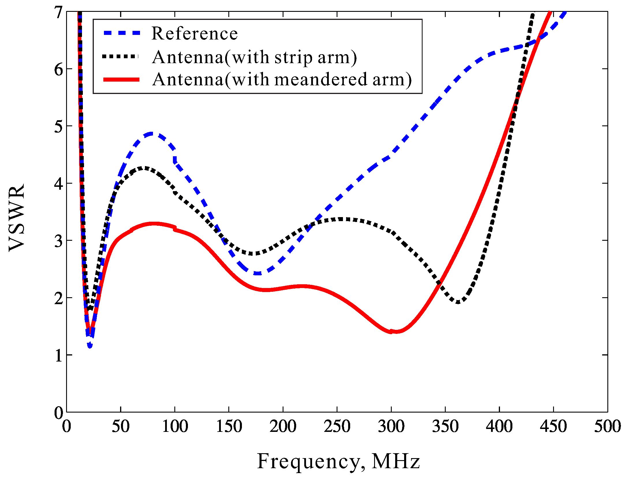
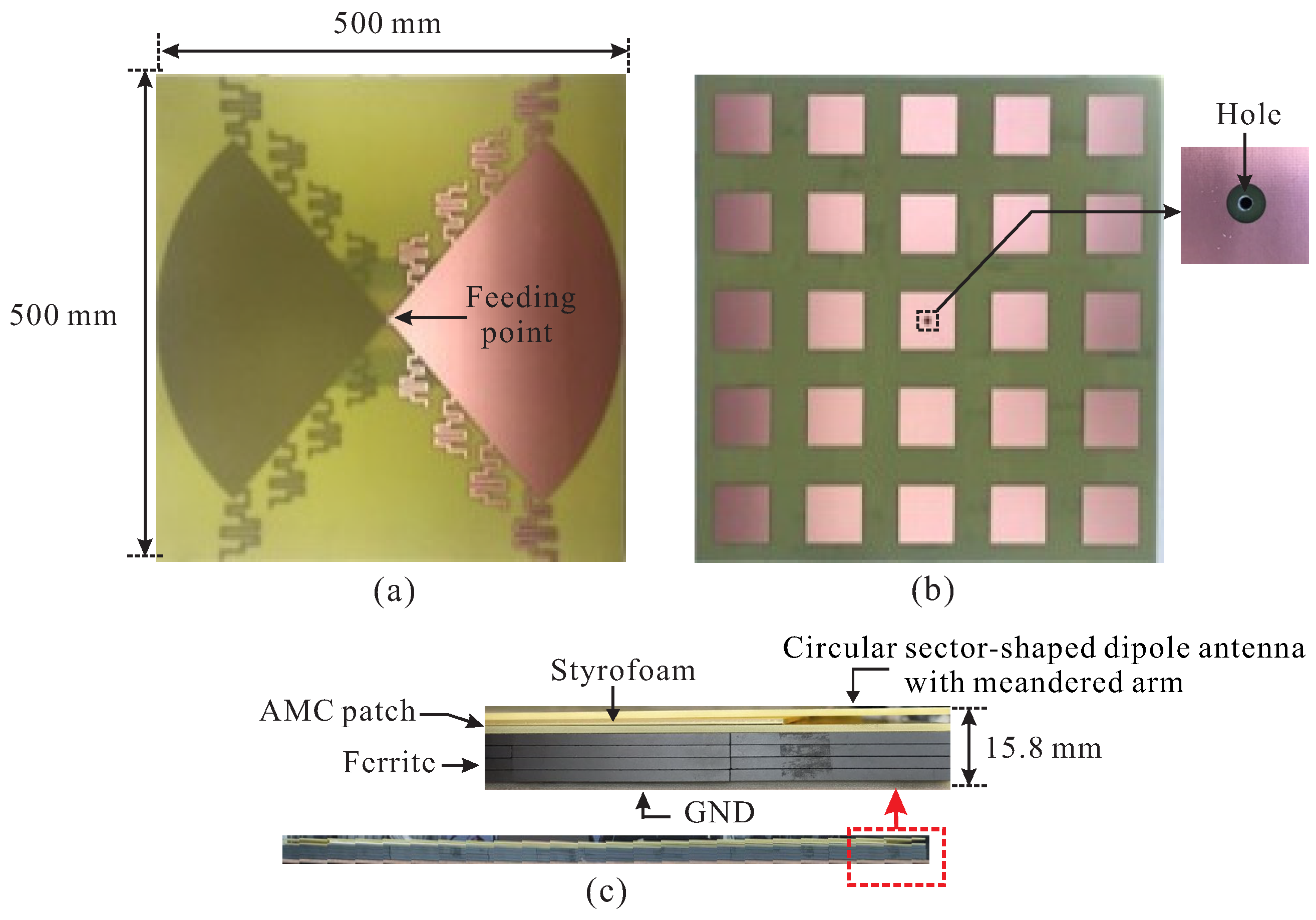
2.2. Design of Circular Sector-Shaped Dipole Antenna with Meandered Arm

Figure 3a presents the design concept for optimizing the meandered arm structure. The shape of the meandered arm is designed using the method proposed by Bayraktar et al. [26] to operate in the HF, VHF, and UHF bands. The design sequence begins with dividing the area where the meandered arm is positioned into nine segments of identical lengths. Each divided segment is designated as one column of the grid, which is marked in blue. The binary genetic algorithm (GA) is used to decide the optimal position of each segment, and the three bits are encoded to assign eight states. Two adjacent segments in the optimal position are connected by vertical lines marked in red. The size of the horizontal and vertical components of the meandered arm are 13.2 × 13.2 mm 2 , and 5.5 × 5.5 mm 2 , respectively. The optimally designed meandered arm is reduced by the scaling factor k = 0.9 and positioned in a space between the elements from d 1 to d 3 . The optimized values for d 1 , d 2 , and d 3 were 69.9 mm, 62.6 mm, and 62.4 mm, respectively.
After optimizing the configuration and spacing parameters, the meandered arms are symmetrically duplicated as A n (n = 1,2,3,4) (Figure 3b). The binary GA optimization process also optimizes the scaling factor k and spacing element d n (n = 1,2,3), and each design parameter is assigned eight bits. Therefore, 59 bits are used in total during the binary GA optimization process. The binary GA optimization is performed using MATLAB programming, with the script interface connecting to the CST program. The 100 iterations of the binary GA take 20 populations into consideration, and use a 0.1 mutation rate through the single-point crossover scheme. The optimization condition is to satisfy the bandwidth of VSWR 3.5:1 or less as wide as possible in the HF, VHF, and UHF bands. Figure 3b shows the configuration of the designed dipole antenna. The dipole antenna’s element consists of eight optimized meandered arms existing above and below the circular sector-shaped patch with a radius of P r = 247 mm and a central angle α = 97 .

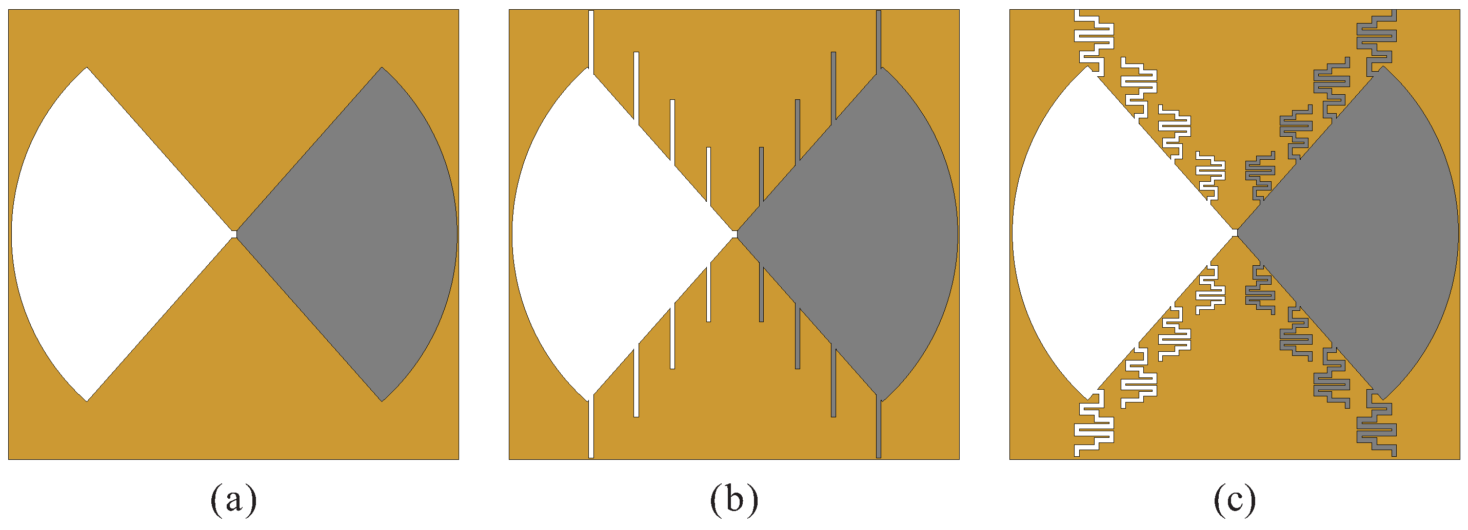
2.3. The Proposed Circular Sector-Shaped Dipole Antenna with AMC

Figure 4a illustrates the shape of a circular sector-shaped dipole antenna combined with a meandered arm. A circular sector-shaped dipole antenna, which is combined with eight meandered arms is symmetrically positioned on the top and bottom surfaces of a 500 × 500 mm 2 FR4 substrate with a dielectric constant of 4.3, a thickness of t s = 1.52 mm, and loss tangent of 0.025. The elements of the dipole antenna located on the upper and lower surfaces are indicated by gray and white, respectively. The antenna was fed through a coaxial cable.
Figure 4b shows the shape of the proposed AMC structure. The AMC structure consists of 25 unit cells, and the size is 500 × 500 mm 2 , which is the same as the dipole antenna. A conductor with a radius of r g =1.5 mm is removed to prevent a short circuit between the AMC unit cell and the coaxial cable, which is used for feeding. Figure 4c shows a side view of a circular sector-shaped dipole antenna combined with an AMC structure. The gap between the circular sector-shaped dipole antenna and the AMC structure is 1 mm.
To check the performance based on the presence and shape of the meandered arm, three antennas were simulated (Figure 5). All antennas are positioned symmetrically on the top and bottom of the FR4 substrate and combined with a 5 × 5 AMC structure.
Figure 6 presents the simulated VSWR characteristics of three types of antennas with and without meandered arms. If the meandered arm structure does not exist, it partially fails to satisfy the VSWR characteristic of 3.5:1 or less in the HF, VHF, and UHF bands. The path through which the surface current can flow is increased by adding a stripe line to a reference antenna [27]. This caused an additional resonance mode, resulting in the improvement of antenna matching characteristics in the high-frequency band, as shown in Figure 6. By adding the strip arm, not only the path through which the surface current can flow increases, but also the wideband characteristics of the antenna can be realized due to the additional mutual coupling with the AMC [16]. The stripline was optimized in a meander shape to improve the antenna’s operating bandwidth characteristics; thus, satisfying the VSWR of 3.5:1 or less in the HF, VHF and UHF bands of 14–371 MHz.

3. Designed Antenna Performance

To verify the designed antenna performance, the antenna was fabricated, measured, and compared with the simulation results. Figure 7 depicts the fabricated circular sector-shaped dipole antenna with the AMC. The circular sector shape combined with the meandered arm, which is an element of the dipole antenna, is symmetrically positioned. The AMC was fabricated by stacking four ferrite layers with a height of 2.5 mm to achieve a 10 mm height. The area between the dipole antenna and the AMC was implemented using a 1 mm thick styrofoam. The dimensions of the designed antenna are 0.02 × 0.02 × 0.0007 λ 3 L ( λ L is the wavelength at 14 MHz).
Figure 8 presents the simulated and measured VSWR characteristics of the designed dipole antenna with an AMC. VSWR was measured by connecting the antenna’s coaxial cable and Agilent 8510C network analyzer in an anechoic chamber. Both the simulated and measured VSWR results satisfy the characteristics below 3.5 in the 14–361 MHz HF/VHF/UHF bands and the trends of the two graphs is similar. The difference between the simulated and measured results is due to manufacturing and measurement errors.
Figure 9 illustrates the simulated radiation patterns of a circular sector-shaped dipole antenna with the AMC structure at 14, 200, and 370 MHz in the xz and yz-planes. Because the AMC acts as a reflector, it causes the radiation pattern to be focused in the +z-axis. Additionally, due to the image current formed on the AMC’s surface, the characteristic of the antenna do not deteriorate even though it is closer than λ L /4, which is the required separation distance from the general reflector. Thus, low-profile characteristics were achieved in HF, VHF, and UHF bands.
Figure 10 depicts the simulated realized gain on the +z-axis of a circular sector-shaped dipole antenna based on the AMC structure. The main polarization characteristic of the proposed antenna is horizontal polarization and has a gain of −38 to −1.75 dBi in the operating bandwidth of 14 to 371 MHz.

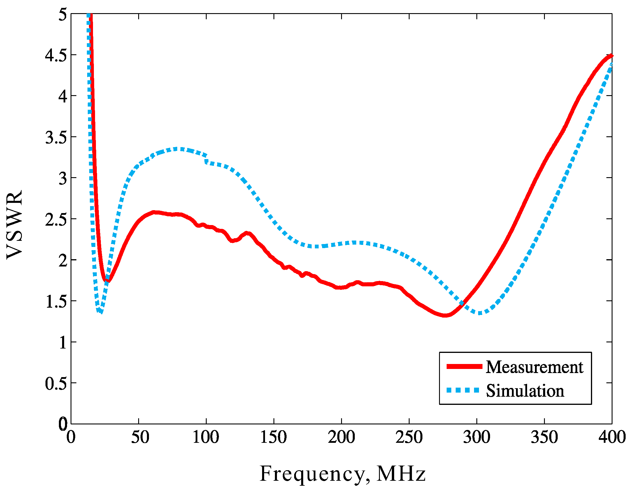
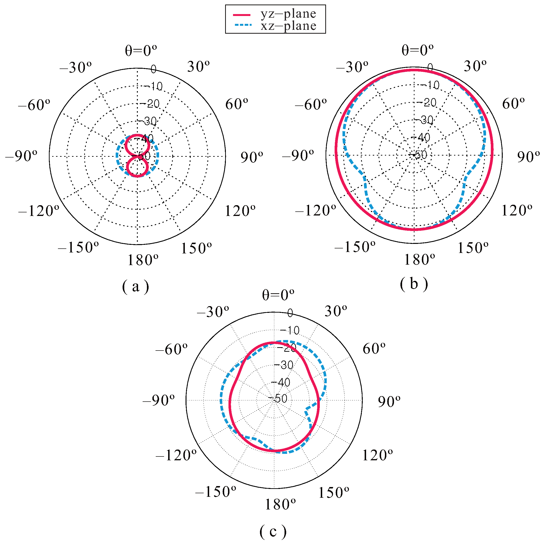
4. Experimental Results

A commercial antenna operating in the HF, VHF, and UHF bands was selected as a reference antenna to verify the performance of the proposed antenna [28]. When the same power is transmitted from the transmit antenna [29], the received power of the proposed and the reference antenna was measured and compared.
Figure 11 shows the received power measurement environment. The size of the proposed antenna is 500 × 500 × 15.8 mm 3 and the height of the commercial reference antenna is 1000 mm and the diameter is 37 mm. The far-field conditions of the antennas are 0.6 m and 2.4 m or more based on the size of each antenna and the highest operating frequency, respectively. The transmit and receive antennas were spaced 70 m in the line of sight. According to the datasheet, the reference antenna is placed on the ground plane with a dimension of 1000 × 1000 mm 2 . The main polarization of the reference antenna and transmit antenna is vertical. Therefore, when measuring the proposed antenna, the received power of vertical and horizontal components was measured by rotating the proposed antenna according to the line shown in the Figure 11.
Figure 12 presents the measured received power of the proposed and reference antennas. The transmitted power from the transmit antenna is 17 dBm, and the received power is measured at 10 MHz steps. The received power difference between the reference and proposed antennas is 1.9 dB on average. The difference in received power is considered to be caused by the difference in the proposed and reference antenna sizes. However, considering the size and height difference between the proposed and reference antennas, the proposed antenna has good receive power characteristics. Therefore, the proposed antenna can be used as a receive antenna in HF, VHF, and UHF bands.

5. Conclusions

In this study, we proposed a circular sector-shaped dipole antenna combined with a meandered arm, which is based on the AMC. An AMC unit cell is designed using a high-permeability ferrite in the HF, VHF, and UHF bands. The circular sector-shaped dipole antenna is combined with the AMC to achieve a low-profile characteristic. The designed antenna improved the operating bandwidth in the HF, VHF, and UHF bands by implementing optimized meandered arms. The VSWR frequency bandwidth ratio of 3.5:1 or less of the designed antenna is 25.8:1, and the size is 0.02 × 0.02 × 0.0007 λ 3 L ( λ L is the wavelength at the lowest operating frequency). The designed antenna was compared with a commercial reference antenna to verify its performance. For these simulation and measurement results, the proposed antenna can be used as a receive antenna that requires low-profile characteristics to be mounted on a small moving object, such as a ground vehicle.

Author Contributions

Conceptualization, D.H.L. and K.C.H.; methodology, D.H.L.; software, D.H.L.; validation, D.H.L., O.H.K. and W.B.P.; formal analysis, D.H.L.; investigation, D.H.L. and O.H.K.; resources, D.H.L. and W.B.P.; data curation, D.H.L.; writing—original draft preparation, D.H.L.; writing—review and editing, D.H.L., O.H.K., W.B.P. and K.C.H.; visualization, D.H.L.; supervision, D.H.L.; project administration, K.C.H.; funding acquisition, K.C.H. All authors have read and agreed to the published version of the manuscript.

Funding

This work has been supported by the Future Combat System Network Technology Research Center program of Defense Acquisition Program Administration and Agency for Defense Development (UD190033ED).

Institutional Review Board Statement

Not applicable.

Informed Consent Statement

Not applicable.

Data Availability Statement

Not applicable.

Conflicts of Interest

The authors declare no conflict of interest.

References

  1. Mi, S.; Lee, Y.H.; Shen, Z. Ferrite Coating Design for Near-Ground HF Bowtie Antenna. IEEE Trans. Antennas Propag. 2017, 65, 2074–2078. [Google Scholar] [CrossRef]
  2. Bouvy, A.; Behdad, N. A Heuristic Study of the Bandwidth Potential of Electrically Small, Platform-Based Antennas at the HF Band. IEEE Trans. Antennas Propag. 2021, 69, 623–635. [Google Scholar] [CrossRef]
  3. Garrido Lopez, D.; Ignatenko, M.; Filipovic, D.S. Low-Profile Tri-band Inverted-F Antenna for Vehicular Applications in HF and VHF Bands. IEEE Trans. Antennas Propag. 2015, 63, 4632–4639. [Google Scholar] [CrossRef]
  4. Best, S.R.; Hanna, D.L. A Performance Comparison of Fundamental Small-Antenna Designs. IEEE Antennas Propag. Mag. 2010, 52, 47–70. [Google Scholar] [CrossRef]
  5. Baker, J.M.; Iskander, M.F. A New Design Approach for Electrically Small High-Frequency Antennas. IEEE Antennas Wirel. Propag. Lett. 2015, 14, 402–405. [Google Scholar] [CrossRef]
  6. SaiRam, C.; Vakula, D.; Chakravarthy, M. Design of Broadband Compact Canonical Triple-Sleeve Antenna Operating in UHF Band. J. Electromagn. Eng. Sci. 2021, 21, 291–298. [Google Scholar] [CrossRef]
  7. Sievenpiper, D.F.; Dawson, D.C.; Jacob, M.M.; Kanar, T.; Kim, S.; Long, J.; Quarfoth, R.G. A compact filtering microstrip antenna with quasi-elliptic broadside antenna gain response. IEEE Trans. Antennas Propag. 2012, 60, 8–19. [Google Scholar] [CrossRef]
  8. Gunamony, S.L.; Gnanadhas, J.B.; Lawrence, D.E. Design and Investigation of a Miniaturized Single-Layer ACS-Fed Dual Band Antenna for LTE and 5G Applications. J. Electromagn. Eng. Sci. 2020, 20, 213–220. [Google Scholar] [CrossRef]
  9. Jin, P.; Lin, C.; Ziolkowski, R.W. Multifunctional, Electrically Small, Planar Near-Field Resonant Parasitic Antennas. IEEE Antennas Wirel. Propag. Lett. 2012, 11, 200–204. [Google Scholar]
  10. Choi, Y.-S.; Hong, J.-H.; Woo, J.-M. Electrically and Frequency-Tunable Printed Inverted-F Antenna with a Perturbed Parasitic Element. J. Electromagn. Eng. Sci. 2020, 20, 164–168. [Google Scholar] [CrossRef]
  11. Min, K.-S. Multiband Cross-Shaped Inverse Triangular Notch Antenna for Radio Shadow Zone Communication. J. Electromagn. Eng. Sci. 2020, 20, 320–326. [Google Scholar] [CrossRef]
  12. Tang, M.; Ziolkowski, R.W.; Xiao, S.; Li, M. A High-Directivity, Wideband, Efficient, Electrically Small Antenna System. IEEE Trans. Antennas Propag. 2014, 62, 6541–6547. [Google Scholar] [CrossRef]
  13. Tang, M.; Chen, X.; Li, M.; Ziolkowski, R.W. Particle Swarm Optimized, 3-D-Printed, Wideband, Compact Hemispherical Antenna. IEEE Antennas Wirel. Propag. Lett. 2018, 17, 2031–2035. [Google Scholar] [CrossRef]
  14. Zhu, N.; Ziolkowski, R.W. Active Metamaterial-Inspired Broad-Bandwidth, Efficient, Electrically Small Antennas. IEEE Antennas Wirel. Propag. Lett. 2011, 10, 1582–1585. [Google Scholar] [CrossRef]
  15. Tang, M.; Zhu, N.; Ziolkowski, R.W. Augmenting a Modified Egyptian Axe Dipole Antenna With Non-Foster Elements to Enlarge Its Directivity Bandwidth. IEEE Antennas Wirel. Propag. Lett. 2013, 12, 421–424. [Google Scholar] [CrossRef]
  16. Fan, Y.; Rahmat-Samii, Y. Reflection phase characterizations of the EBG ground plane for low profile wire antenna applications. IEEE Trans. Antennas Propag. 2003, 51, 2691–2703. [Google Scholar]
  17. Feresidis, A.P.; Goussetis, G.; Shenhong, W.; Vardaxoglou, J.C. Artificial magnetic conductor surfaces and their application to low-profile high-gain planar antennas. IEEE Trans. Antennas Propag. 2005, 53, 209–215. [Google Scholar] [CrossRef]
  18. Lee, J.-G. Compact and Robust Fabry-Perot Cavity Antenna with PEC Wall. J. Electromagn. Eng. Sci. 2021, 21, 184–188. [Google Scholar] [CrossRef]
  19. Kwon, O.H.; Park, W.B.; Yun, J.; Lim, H.J.; Hwang, K.C. A Low-Profile HF Meandered Dipole Antenna with a Ferrite-Loaded Artificial Magnetic Conductor. Appl. Sci. 2021, 11, 2237. [Google Scholar] [CrossRef]
  20. Kwon, O.H.; Hwang, K.C. Low-Profile Spidron Fractal Dipole Antenna with a Ferrite-Loaded Artificial Magnetic Conductor for Manpack Applications. Appl. Sci. 2020, 10, 8843. [Google Scholar] [CrossRef]
  21. Bell, J.M.; Iskander, M.F.; Lee, J.J. Ultrawideband Hybrid EBG/Ferrite Ground Plane for Low-Profile Array Antennas. IEEE Trans. Antennas Propag. 2007, 55, 4–12. [Google Scholar] [CrossRef]
  22. Diaz, R. Magnetic loading of artificial magnetic conductors for bandwidth enhancement. In Proceedings of the IEEE Antennas and Propagation Society International Symposium. Digest. Held in Conjunction with: USNC/CNC/URSI North American Radio Sci. Meeting (Cat. No.03CH37450), Columbus, OH, USA, 22–27 June 2003. [Google Scholar]
  23. MP2106-0M0. Available online: https://www.laird.com/sites/default/files/mp2106-0m0-datasheet.pdf (accessed on 10 June 2022).
  24. Trinh-Van, S.; Kwon, O.H.; Jung, E.; Park, J.; Yu, B.; Kim, K.; Seo, J.; Hwang, K.C. A Low-Profile High-Gain and Wideband Log-Periodic Meandered Dipole Array Antenna with a Cascaded Multi-Section Artificial Magnetic Conductor Structure. Sensors 2019, 19, 4404. [Google Scholar] [CrossRef] [PubMed] [Green Version]
  25. Rexhepi, T.; Crouse, D. A Study of Composite Substrates for VHF and UHF Artificial Magnetic Conductors and Their Application to a SATCOM Antenna. Prog. Electromagn. Res. C 2016, 64, 1–9. [Google Scholar] [CrossRef]
  26. Bayraktar, Z.; Werner, P.L.; Werner, D.H. The design of miniature three-element stochastic Yagi-Uda arrays using particle swarm optimization. IEEE Antennas Wirel. Propag. Lett. 2006, 5, 22–26. [Google Scholar] [CrossRef]
  27. Kang, G.; Wang, F.; Tian, Y.; Ji, Y. A Compact Broadband Antenna for Wireless Terminals in Telemetry and Communication Systems. Eur. Telem. Test Conf. 2014, 172–175. [Google Scholar]
  28. OMNI-A0245. Available online: https://www.alarisantennas.com/wp-content/uploads/2017/06/brochures/OMNI-A0245%20Version%201.2.pdf (accessed on 10 June 2022).
  29. Park, W.B.; Trinh-Van, S.; Yang, Y.; Lee, K.-Y.; Yu, B.; Park, J.; You, H.; Hwang, K.C. A Low-Profile Ferrite Dipole VHF Antenna for Integrated Mast Applications. Appl. Sci. 2020, 10, 1642. [Google Scholar] [CrossRef]
Figure 1. Configuration of the proposed unit cell of the AMC: (a) perspective-view; (b) boundary condition.
Applsci 12 09149 g001
Figure 2. Simulated reflection phase for the unit cell of the designed AMC.
Applsci 12 09149 g002
Figure 3. Design concept of the proposed antenna: (a) meandered arm; (b) circular sector-shaped dipole antenna; (c) optimized meandered arm, A 1 .
Applsci 12 09149 g003
Figure 4. Configuration of proposed antenna with the AMC structure: (a) circular sector-shaped dipole antenna; (b) 5 × 5 AMC structure; (c) side view.
Applsci 12 09149 g004
Figure 5. Three types of antennas with AMC: (a) reference; (b) with strip arms; (c) with meandered arms.
Applsci 12 09149 g005
Figure 6. Simulated VSWR characteristics of three types of antenna.
Applsci 12 09149 g006
Figure 7. Photographs of a fabricated circular sector-shaped dipole antenna with an AMC structure: (a) circular sector-shaped dipole antenna; (b) 5 × 5 AMC structure; (c) side view.
Applsci 12 09149 g007
Figure 8. Simulated and measured VSWR characteristics of the proposed antenna.
Applsci 12 09149 g008
Figure 9. Simulated radiation pattern of the proposed antenna in the xz and yz−planes: (a) 14 MHz; (b) 200 MHz; (c) 370 MHz.
Applsci 12 09149 g009
Figure 10. Simulated realized gain of a proposed antenna on the +z−axis.
Applsci 12 09149 g010
Figure 11. Received power measurement environment.
Applsci 12 09149 g011
Figure 12. Measured received power of a proposed antenna and reference antenna.
Applsci 12 09149 g012
Table 1. Comparison of the proposed AMC and AMC in previous studies (note that λ L is the wavelength of the lowest operating frequency).
Ref.Operating Frequency BandwidthSize ( λ 3 L )
[19]1.89:10.007 × 0.007 × 0.0006
[22]2:10.009 × 0.009 × 0.0005
[25]7.23:10.003 × 0.003 × 0.0015
Proposed AMC25.5:10.006 × 0.006 × 0.0008
Publisher’s Note: MDPI stays neutral with regard to jurisdictional claims in published maps and institutional affiliations.

