Article

Instability and Atomization of Liquid Cylinders after Shock Wave’s Impacting

College of Mechanical Engineering and Automation, Zhejiang Sci-Tech University, Hangzhou 310018, China
*
Author to whom correspondence should be addressed.
Appl. Sci. 2022, 12(24), 12597; https://doi.org/10.3390/app122412597
Submission received: 13 November 2022 / Revised: 1 December 2022 / Accepted: 6 December 2022 / Published: 8 December 2022

Abstract

:
This paper describes an experimental study on the instability and atomization of liquid cylinders after the impact of shock waves. Single row water column, in-line double rows water columns and alongside triple rows water columns were evaluated in a horizontal shock tube. The diameter of water column and the Mach number in the experiments were 2.0–4.14 mm and 1.10–1.25, respectively. The global instability along the axial direction of water cylinders was focused. Using a high-speed camera, the developments of spike height, bubble depth and turbulent mixing zone, width were measured. Some comparison was also made between the present experimental results and the existing theoretical model.

1. Introduction

The interaction between a shock wave and a liquid cylinder can be seen in atomization and combustion in Scramjet engines [1,2,3]. Research on the instability model of the liquid is key to evaluate efficiency in fuel mixing and combustion. On the other hand, results of the Richtmyer–Meshkov (RM) instability at a gas/liquid interface can be applied in design of inertial confined fusion (ICF) because it provides a case of large Atwood number [4,5,6].
In fact, people have been familiar with the phenomenon of shock wave interaction with a liquid droplet. In 1959, Gordon [7] established a theoretical model of predicting the breakup time of a droplet in highspeed gas stream after shock wave’s impact. Later, Wierzba and Takayama [8] and Hisang and Faeth [9,10] experimentally investigated different types of droplet breakup induced by shock wave. In 2001, Igra and Takayama [11] simulated shock wave interaction with a water cylinder using CIP format. In 2008, Chen and Liang [12] conducted a similar numerical work using a compressible multiphase solver with a five-equation model. In 2016, Wang et al. [13] simulated deformation and disintegration of a two-dimensional water drop, in which their numerical results are in agreement with the experimental results. They found the effect of liquid viscosity on the vortex structure behind the drop and investigated the influence of Weber number and Ohnesorge number on breakup of the drop. Recently, based on unsteady Reynolds-averaged Navier–Stokes approach and VOF method, Rossano [14,15,16] effectively reproduced the aerobreakup process under the shear-induced entrainment regime. Wherein the results presented by the hybrid VOF–Lagrangian method are very commendable. Moreover, the adaptive numerical mesh approach can well capture the phase interface, which provides a good example for the numerical simulation method to study RM instability.
Research on wave dynamics has also been widely concerned by scholars [17,18,19]. For example, Guan et al. [18] used numerical simulations to focus on the internal flow pattern of a droplet and observed that a high pressure develops in the leeward region of the droplet due to the collision of the transmitted and diffracted shock wave, which flattens the entire droplet. These studies have clarified in detail that the complex wave structure generated by the interaction between shock wave and droplets, is fully capable of deforming the droplet at the early stage of the impact.
Perhaps the earliest experiment on shock wave interaction with a liquid cylinder was conducted at Tohoku University, Japan, using a thin gel layer to represent a water cylinder [20]. In 2016, the Royal Institute of Technology, Sweden conducted an experiment of shock wave’s impact on a 5 mm height water cylinder aiming to reveal the wave propagation in the cylinder [21]. Further, Xu and Wang [22] investigated the interaction between the plane shock and two concentric/eccentric cylinders, which are formed by the improved soap film technique.
However, none of the experiments have been concerned with the global deformation and disintegration along the axial direction of the cylinder. This paper will report an experimental work on the instability and atomization of relatively long water cylinders produced by gravity.

2. Experimental Devices

Figure 1 shows the horizontal shock tube applied in our experiment, whose total length is about 12 m. The high-pressure gas tank 1 (nitrogen N2 gas), round cross low pressure section 5 and square cross low-pressure section 6 composes the shock wave generator. The experimental section 9 is connected to the square cross low-pressure section and vacuum chamber 14 by flanges and two pressure transducers 7 for measuring shock Mach number are set on the top of the square cross low-pressure section 6. Figure 2 is the enlarged schematic of the experimental section 8. The interior sectional dimension of the 500 mm long experimental section is 120 mm × 120 mm. A highspeed camera (Photon Fastcam SA5) is set at one side of the experimental section 8 which is windowed by two transparent PMMA plates. If shadowgraph or schlieren optics is applied, the shock waves can also be visualized. On the upper and lower walls of the experimental section 8, square holes are machined respectively to arrange the water cylinder adapter 16, testing plate 17 and lower drainage board 18. The water cylinder adapter 16 is fixed on the testing plate 17 through screw structure. The outlet of the adapter 16 is machined carefully to ensure that a long smooth water cylinder can be obtained [23]. In Figure 2, it is also shown that the in-line double rows water columns can be obtained with 50 mm spacing distance. Using the shock tube, we already successfully conducted experiments on shock wave interaction with water droplet (see [13,24]).
After the shock wave’s impact, the water cylinder (column) will experience processes of compression, RM instability, disintegration, atomization, etc. The RM instability will produce the so-called spike and bubble structures. Therefore, measurements of the spike height and bubble depth h b are important to describe how the instability develops, which are shown in Figure 3. In Figure 3a, the two successive photos are overlapped each other so that the increment of the spike height Δ h s and increment of bubble depth Δ h b can be obtained. Then, the next time the spike height or bubble depth becomes h 2 = h 1 + Δ h . From Figure 3b,c, the displacement of the vertical axial base line Δ s equals to that taken from high-speed photographs (e.g., Figure 4 and Figure 5). By definition, if we consider the gas/liquid interface as a sinusoidal curve, the distance from the base line to the crest is h s ; the distance from the base line to the trough is h b ; then the turbulent mixing zone is that h = h s + h b . Averaging the results along the axial direction of the cylinder, we have the global parameter:
h i = 1 m n = 1 m h i m ( i = s , b ;   m = 1 , 2 , 3 )

3. Results and Discussion

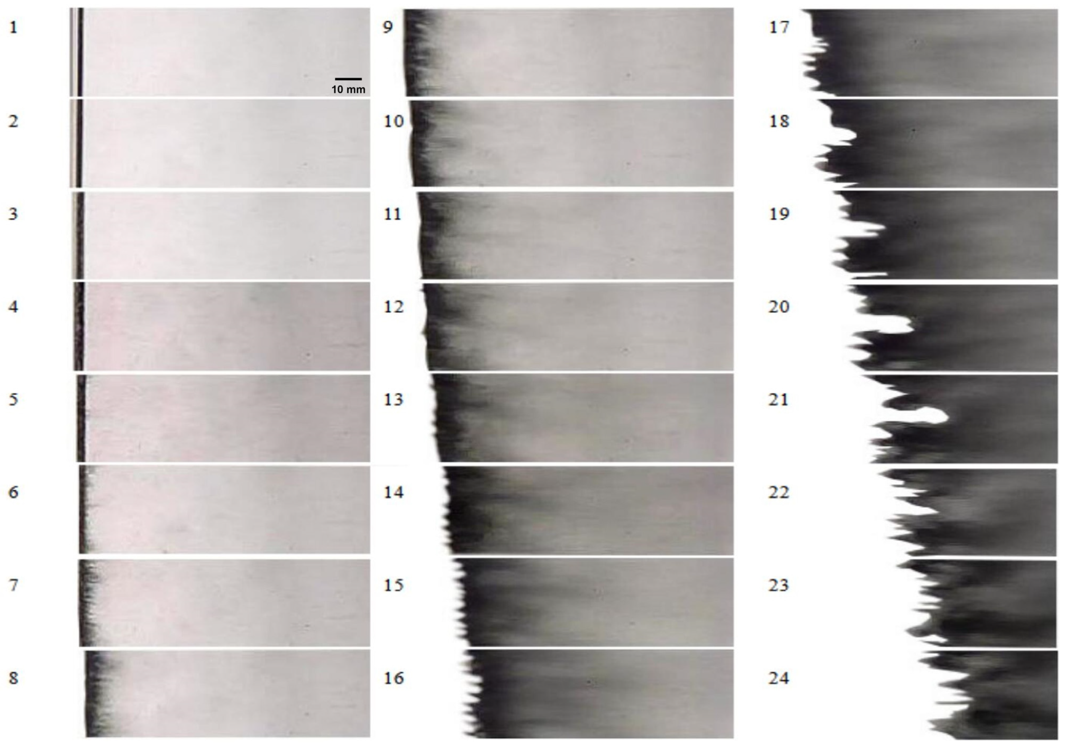
Figure 4 shows high-speed photographs of d 0 = 4.14 mm diameter single row water column after interaction with a M a = 1.10 shock wave. It is seen that from Figure 4(1–5), the cylinder is compressed and moves to the right after shock wave’s impact. The compression duration is longer than that of d 0 = 2.76 mm water cylinder [25]. It should be noted that compression of the liquid column, as mentioned in the introduction, is due to the high-pressure zone formed by the interaction between the diffracted shock wave and the transmitted shock wave [17,18,19]. From Figure 4(6), the liquid is stripped off and many thin ligament tails are formed on the leeward side of the column. From Figure 4(8) to Figure 4(12), the windward side of the column starts to deform and bend but the surface is still smooth. At the moment, the instability has not been developed obviously. From Figure 4(13–16), the spike and bubble structures appear on the windward side of the column. Then, they develop gradually and merge together.
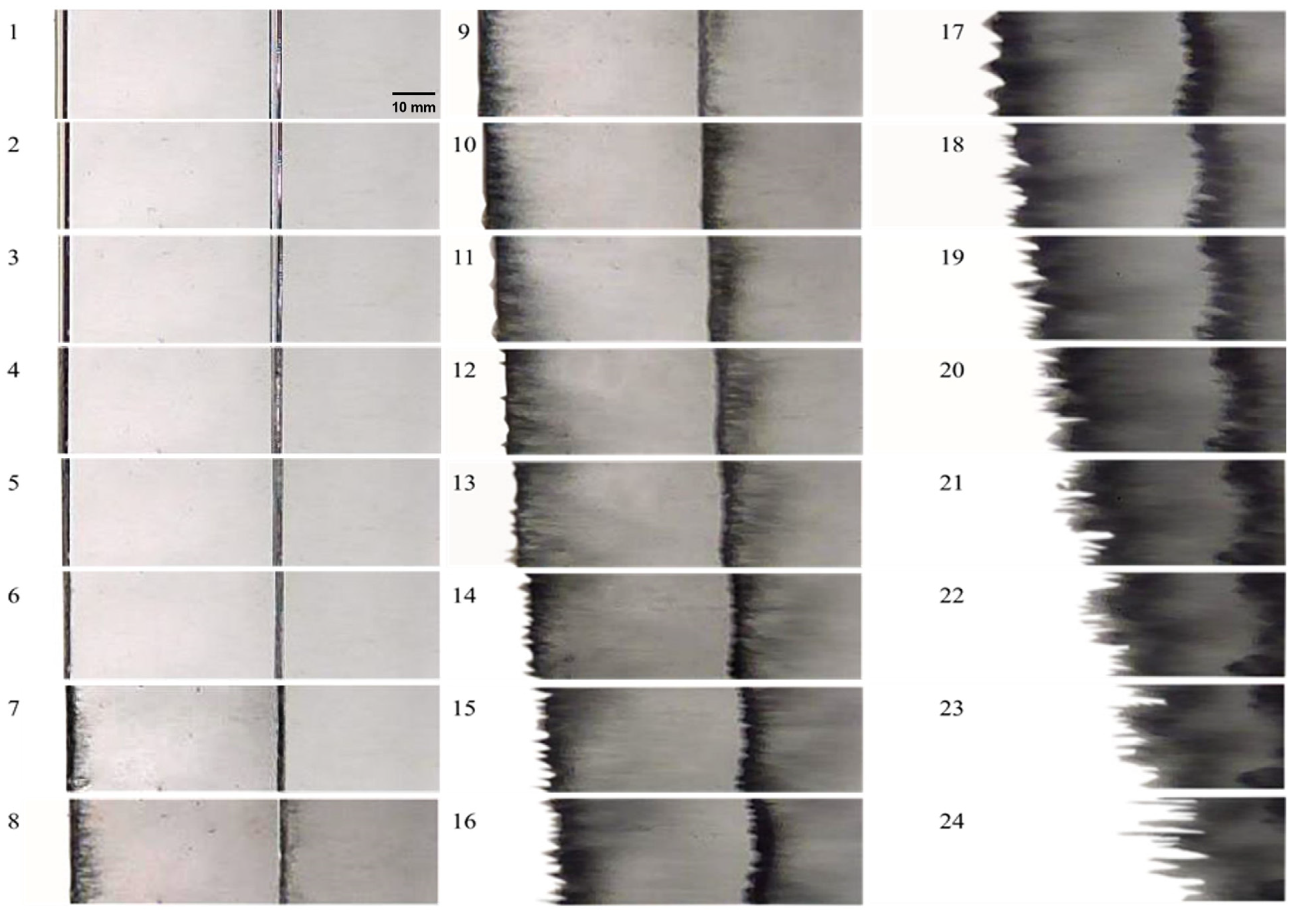
Figure 5 gives high-speed photographs of RM instability after a M a = 1.10 shock wave impacts on d 0 = 3.38 mm diameter in-line double rows water columns. We mark the first one as the left column (L) and the second one as the right column (R). As shown in Figure 5(1–6), after shock wave’s impact, the two columns are compressed and move to the right direction. The motion of the right column lags behind the left one. From Figure 5(7), many thin ligament tails appear on the leeward side of the left column. Meanwhile, in Figure 5(7), the streamwise size of the right column is compressed to minimum. From Figure 5(8–11), as disintegration and atomization of the liquid develop further, the two columns expand gradually and the wakes on the leeward sides integrate with the surrounding air. The spike and bubble structures appear on the windward side of the left column from Figure 5(12) and similar phenomenon occurs on the right column from Figure 5(13). From Figure 5(14–24), the spike and bubble structures develop further and merge with each other; at the later stage, the two columns interact mutually and mix together to form a complicated turbulent cloud. Noticeably, the left column takes precedence to develop because it firstly meets the shock wave. In comparison with the single row water cylinder, the in-line double rows water columns deform and break up more slowly to some degree. This can be explained due to retardation of the left column to the shock wave.
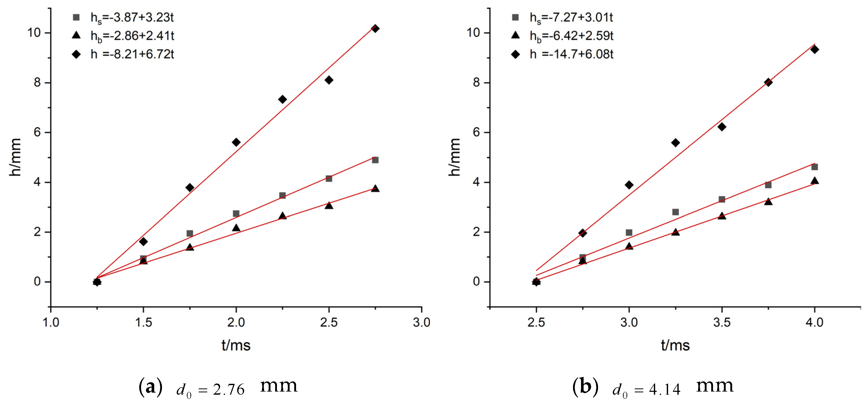
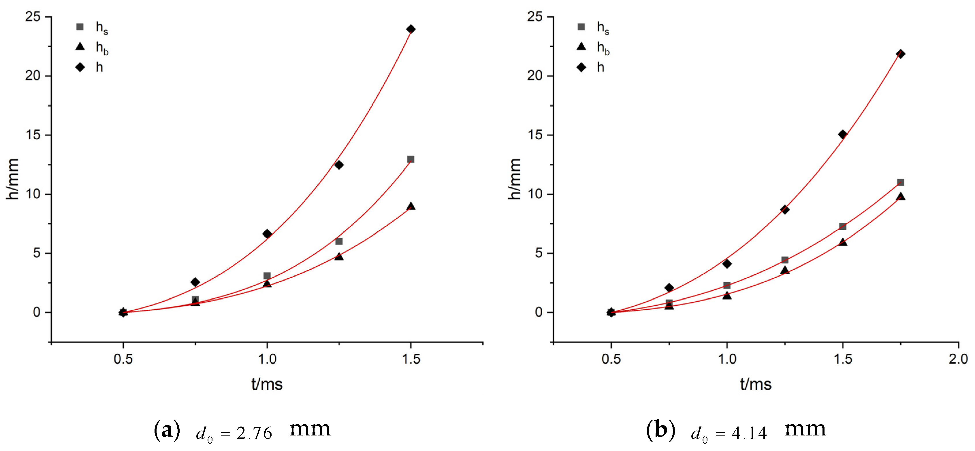
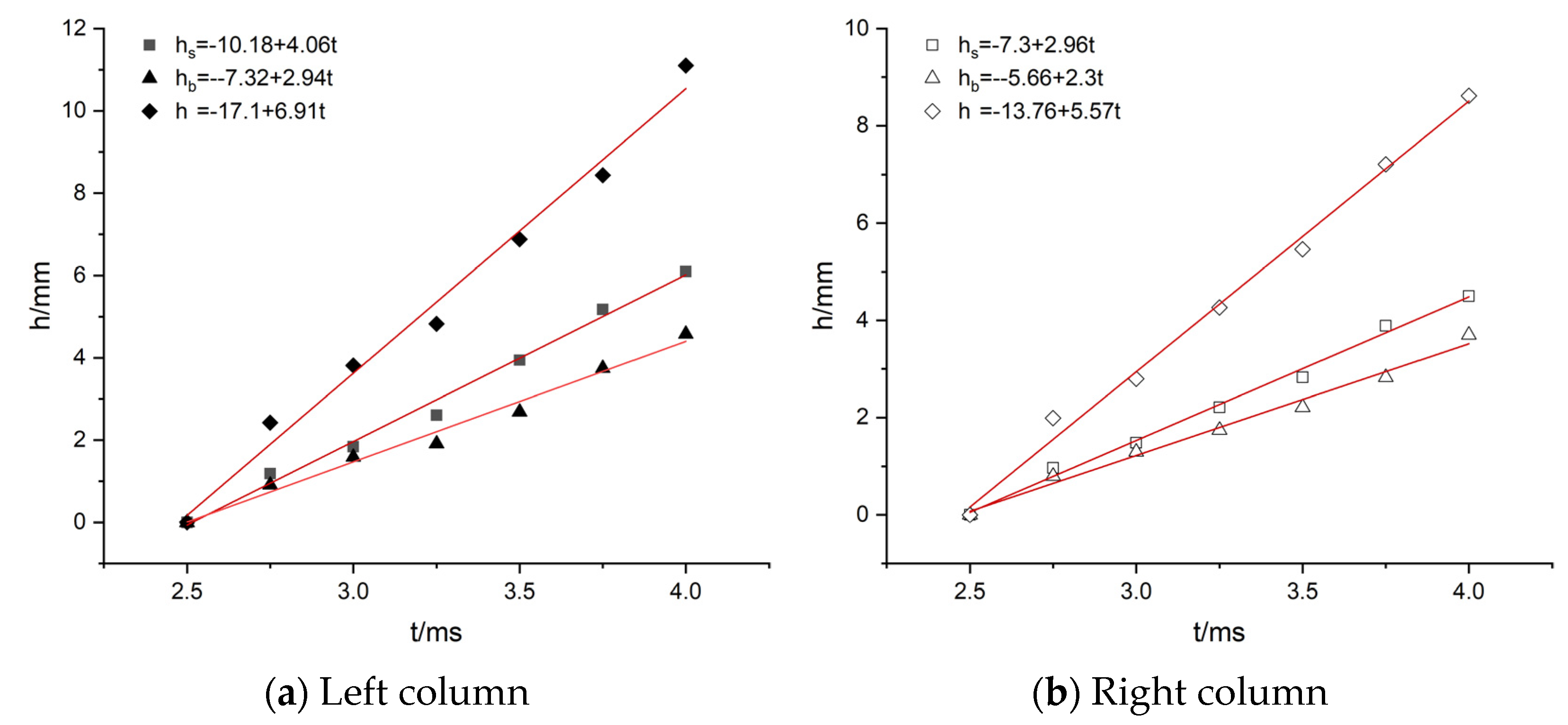
The measured spike height h s , bubble depth h b and turbulent mixing zone h are presented in Figure 6, Figure 7 and Figure 8. It is clear that at M a = 1.10 , the parameters are all linear with time in spite of the single row water column or in-line double rows water cylinders (see Figure 6 and Figure 8). However, as the increase of Mach number to M a = 1.25 , h s , h b and h all become nonlinear with time (see Figure 7).
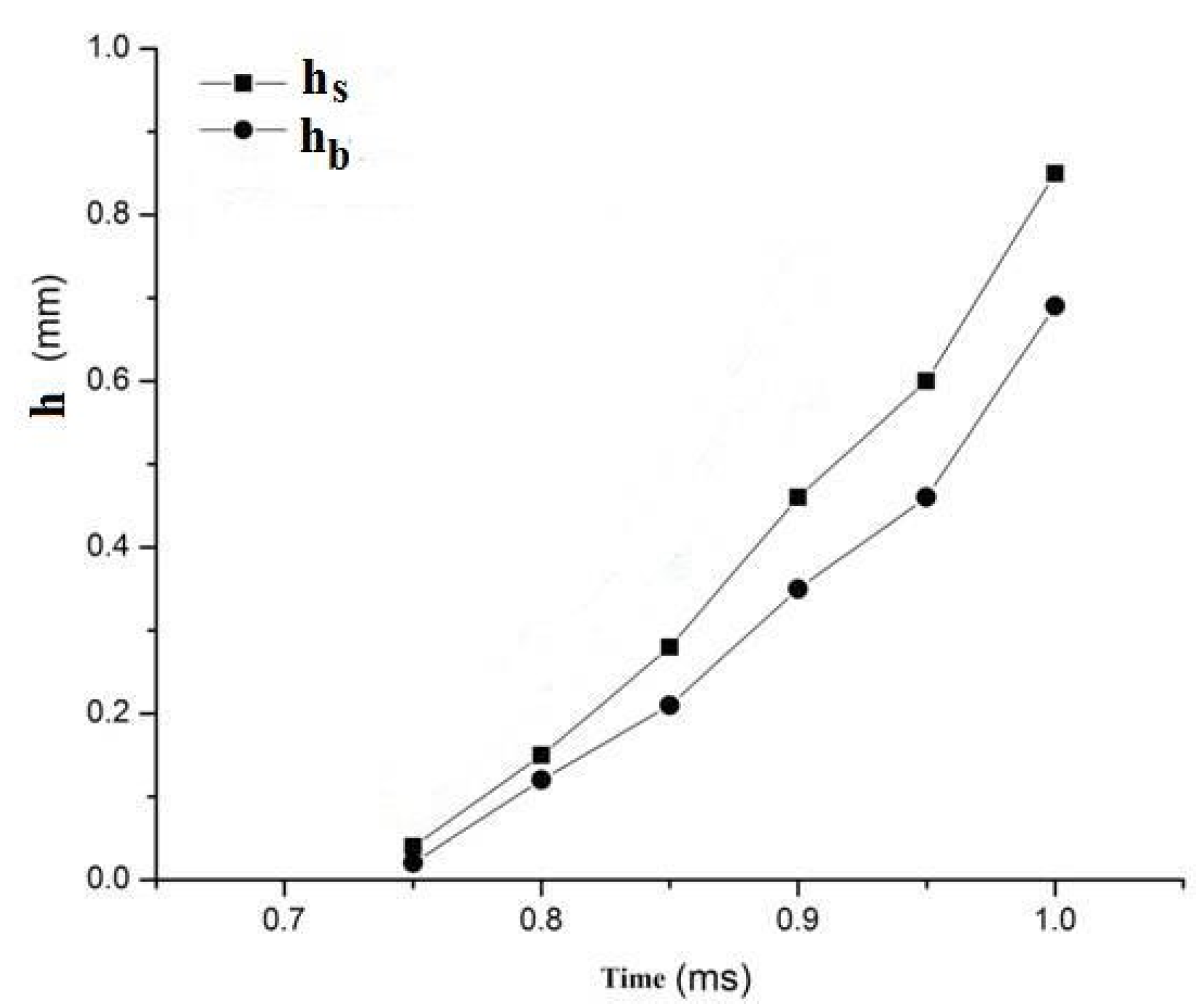
The measured spike height h s , bubble depth h b and turbulent mixing zone h are presented in Figure 6, Figure 7 and Figure 8. Next, we introduce the results of the shock wave interaction with alongside triple rows water columns with 2 mm space of d 0 = 2.0 mm diameter at Mach number M a = 1.20 . The shadowgraphs and numerical schlieren pictures of cross-sectional view are given in Figure 9. It is known that the reflection and diffraction of shock wave from the neighbour cylinders cause a very complex wave system, so that this may bring a nonlinear RM instability. The measurement results of the spike height and bubble depth confirm this postulation (see Figure 10). The results of three dimensional numerical simulations based on Fluent software and VOF method [26,27] give a similar trend. Additionally, a comparison with the single row water column experiment of d 0 = 2.0 mm diameter at Mach number M a = 1.20 at identical conditions demonstrates that the RM instability in case of triple columns has obvious nonlinear characteristics [26,27].
As already known, Richtmyer [28] proposed his famous acoustic linear impact model for the disturbance on a fluid interface as following:
h = 2 α t A Δ ν
A = ρ 2 ρ 1 ρ 2 + ρ 1
In the Atwood number A , ρ 1 and ρ 2 are densities of light fluid and heavy fluid respectively, α is an experimental coefficient. Bases on single mode of disturbance and two bubbles model, Alon et al. [29] obtained a theory for RT and RM instabilities, that is, at any Atwood number h b t 0.4 , and when A 1 , h s t . Nevertheless, according to the experimental results in this paper ( A 1 ), at M a = 1.10 , h s   &   h b t ; at M a = 1.25 , h s   &   h b t 2 . The reasons for nonlinear growth may be complex. It is also related to R-T instability and K-H instability in addition to the complex wave structure effects as just described. In addition, the growth trend of R-T instability is exponential. Therefore, we give the following formula for a better explanation:
h ( t ) = h RM ( t ) + h RT ( t ) + h KH ( t ) +

4. Conclusions

In this paper, we reported the first study on global Richtmyer–Meshkov instability along the axial direction of liquid cylinders. The experimental results reveal that the spike height, bubble depth and turbulent mixing zone can grow linearly with time when the Mach number of shock wave is not great. As the increase in Mach number, the RM instability can become nonlinear. For multiple liquid cylinders, the reflection and diffraction of shock wave from the neighbour cylinders may bring a nonlinear effect into RM instability. The experimental data of this paper are measured at a relatively later stage of the instability. A direct measurement on the very early stage of the instability on a gas/liquid interface is expected in future work.

Author Contributions

Conceptualization, H.-H.S. and R.-L.D.; methodology, H.-H.S. and R.-L.D.; experiment, C.-Y.C.; validation, H.-H.S., R.-L.D. and C.-Y.C.; writing—original draft preparation, C.-Y.C.; writing—review and editing, Y.L.; supervision, R.-L.D. and Y.L.; funding acquisition, R.-L.D. All authors have read and agreed to the published version of the manuscript.

Funding

Zhejiang Province Public Welfare Technology Applicaiton Research Project, Grant Number: LGG19A020002.

Institutional Review Board Statement

Not applicable.

Informed Consent Statement

Not applicable.

Data Availability Statement

All data are contained within the article.

Conflicts of Interest

The authors declare no conflict of interest.

References

  1. Hermanson, J.C.; Papas, P.; Kay, I.W. Structure and penetration of a supercritical fluid jet in supersonic flow. J. Propuls. Power 1994, 10, 387–394. [Google Scholar] [CrossRef]
  2. Li, H.-S.; Kelly, R.E. The instability of a liquid jet in a compressible airstream. Phys. Fluids A 1992, 4, 2162–2168. [Google Scholar] [CrossRef]
  3. Li, H.-S.; Karagozian, A.R. Breakup of liquid jet in supersonic crossflow. AIAA J. 1992, 30, 1919–1921. [Google Scholar] [CrossRef]
  4. Meekunnasombat, P.; Oakley, J.G.; Anderson, M.H.; Bonazza, R. Experimental study of shock-accelerated liquid layers. Shock Waves 2006, 15, 383–397. [Google Scholar] [CrossRef]
  5. Shi, H.H.; Zhang, G.; Du, K.; Jia, H.X. Experimental study of the mechanism of Richtmyer-Meshkov instability at a gas/liquid interface. J. Hydrodyn. Ser. B 2009, 21, 423–428. [Google Scholar] [CrossRef]
  6. Mikaelian, K.O. Extended model for Richtmyer-Meshkov mix. Phys. D Nonlinear Phenom. 2011, 240, 935–942. [Google Scholar] [CrossRef] [Green Version]
  7. Gordon, G.D. Mechanism and speed of breakup of drops. J. Appl. Phys. 1959, 20, 1759–1761. [Google Scholar] [CrossRef]
  8. Wierzba, A.; Takayama, K. Experimental investigation of aerodynamic breakup of liquid drops. AIAA J. 1998, 26, 1329–1335. [Google Scholar] [CrossRef]
  9. Hisang, L.P.; Faeth, G. Near-limit drop deformation and secondary breakup. Int. J. Multiph. Flow 1992, 18, 635–652. [Google Scholar] [CrossRef] [Green Version]
  10. Hisang, L.P.; Faeth, G. Drop deformation and breakup due to shock wave and steady disturbances. Int. J. Multiph. Flow 1995, 21, 545–560. [Google Scholar] [CrossRef]
  11. Igra, D.; Takayama, K. Numerical simulation of shock wave interaction with a water column. Shock Waves 2001, 11, 219–228. [Google Scholar] [CrossRef]
  12. Chen, H.; Liang, S.M. Flow visualization of shock/water column interactions. Shock Waves 2008, 17, 309–321. [Google Scholar] [CrossRef]
  13. Wang, C.; Wu, Y.; Shi, H.H.; Xiao, Y. Breakup process of a droplet under the impact of a shock wave. Explos. Shock Waves 2016, 36, 1775–1779. (In Chinese) [Google Scholar]
  14. Rossano, V.; De Stefano, G. Computational evaluation of shock wave interaction with a cylindrical water column. Appl. Sci. 2021, 11, 4934. [Google Scholar] [CrossRef]
  15. Rossano, V.; Cittadini, A.; De Stefano, G. Computational evaluation of shock wave interaction with a liquid droplet. Appl. Sci. 2022, 12, 1349. [Google Scholar] [CrossRef]
  16. Rossano, V.; De Stefano, G. Hybrid VOF–Lagrangian CFD Modeling of Droplet Aerobreakup. Appl. Sci. 2022, 12, 8302. [Google Scholar] [CrossRef]
  17. Chen, H. Two-dimensional simulation of stripping breakup of a water droplet. AIAA J. 2008, 46, 1135–1143. [Google Scholar] [CrossRef]
  18. Ben, G.; Yao, L.; Yung, W.C.; Hua, S. Numerical Study on Liquid Droplet Internal Flow Under Shock Impact. AIAA J. 2018, 56, 9. [Google Scholar]
  19. Sharma, S.; Singh, A.P.; Rao, S.S.; Kumar, A.; Basu, S. Shock induced aerobreakup of a droplet. J. Fluid Mech. 2021, 929, A27. [Google Scholar] [CrossRef]
  20. Igra, D.; Takayama, K. Investigation of aerodynamic breakup of a cylindrical water droplet. At. Spary 2001, 11, 167–185. [Google Scholar]
  21. Sembian, S.; Liverts, M.; Tillmark, N.; Apazidis, N. Plane shock wave interaction with a cylindrical water column. Phys. Fluids 2016, 28, 056102. [Google Scholar] [CrossRef]
  22. Xu, J.; Wang, H.; Feng, L.; Zhai, Z.; Luo, X. Interaction of a shock with two concentric/eccentric cylinders. Exp. Fluids 2021, 62, 1–12. [Google Scholar] [CrossRef]
  23. Shi, H.H.; Xiao, Y.; Wu, Y. A Device Applied for the Interaction between Shock Waves and Various Shapes’ Liquids. Chinese Patent No. ZL201220233805.7, 23 May 2012. (In Chinese). [Google Scholar]
  24. Xiao, Y.; Shi, H.H.; Wu, Y.; Wang, C.; Zhang, L.T.; Dong, R.L. Experimental study of the shock-induced acceleration and breakup of liquid droplets. In Proceedings of the 29th lnternational Symposium on Shock Waves, CD-ROM, Paper No. 0246-000071. Madison, WI, USA, 14–19 July 2013. [Google Scholar]
  25. Shi, H.H.; Xiao, Y.; Wu, Y.; Zhang, L.T.; Wang, C.; Dong, R.L. Experimental study of the Richtmyer−Meshkov instability in the interaction of shock waves with liquid column. J. Eng. Thermophys. 2014, 35, 1775–1779. (In Chinese) [Google Scholar]
  26. Zhang, K. The Mechanism of Liquid Columns’ Deformation and Breakup Process under the Action of Shock Wave. Master’s Thesis, Zhejiang Sci-Tech University, Hangzhou, China, 2015. (In Chinese). [Google Scholar]
  27. Shi, H.H.; Wang, T.Y.; Liu, J.H.; Zhang, K.; Dong, R.L.; Zhang, Y.B. Research on deformation and breakup of multiple liquid cylinders after the impact by shock waves. J. Eng. Thermophys. 2020, 41, 1931–1939. (In Chinese) [Google Scholar]
  28. Richtmyer, R.D. Taylor instability in shock acceleration of compressible fluids. Commun. Pure Appl. Math. 1960, 13, 297–319. [Google Scholar] [CrossRef]
  29. Alon, U.; Hecht, J.; Ofer, D.; Shvarts, D. Power laws and similarity of Rayleigh-Taylor and Richtmyer-Meshkov mixing fronts at all density ratios. Phys. Rev. Lett. 1995, 74, 534–537. [Google Scholar] [CrossRef] [PubMed]
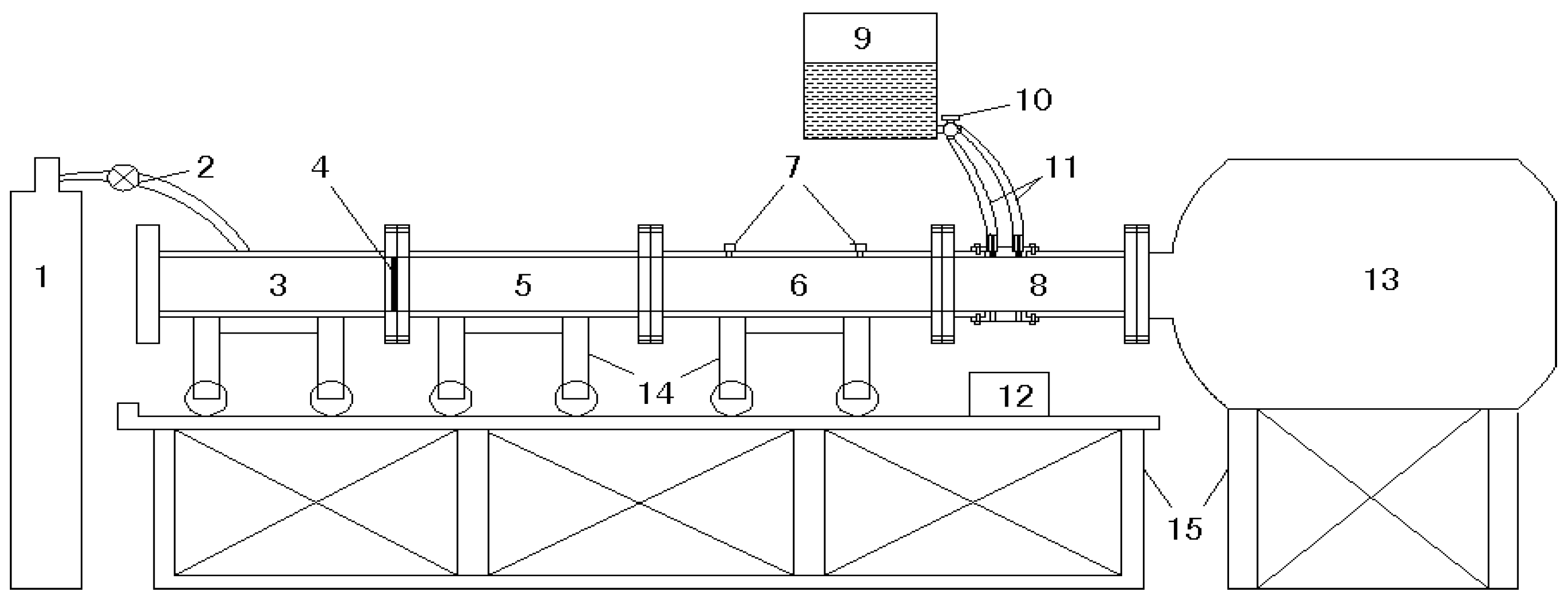
Figure 1. Schemes follow the same formatting. 1. High pressure gas tank; 2. Gas valve; 3. High pressure section; 4. Aluminium foil; 5. Round cross low-pressure section; 6. Square cross low-pressure section; 7. Pressure transducer 8. Experimental section; 9. Water tank; 10. Water inlet valve; 11. Water tube; 12. Water container; 13. Vacuum chamber; 14. Trolley; 15. Support.
Applsci 12 12597 g001
Figure 2. Sectional view of the experimental section. 16. Water cylinder adapter; 17. Testing plate; 18. Lower drainage board.
Applsci 12 12597 g002
Figure 3. Measurement of the spike height and bubble depth. (a) Definition of h s and h b ; (b,c) Definition of the vertical axial base line and Δ s .
Applsci 12 12597 g003
Figure 4. High-speed photographs of RM instability of d 0 = 4.14 mm diameter water cylinder at Mach number M a = 1.10 . Part 1–24 show the image at 0.25 ms interval.
Applsci 12 12597 g004
Figure 5. High-speed photographs of double d 0 = 3.38 mm diameter water cylinders at Mach number M a = 1.10 . Part 1–24 show the image at 0.25 ms interval.
Applsci 12 12597 g005
Figure 6. Evolution of spike height, bubble depth and turbulent mixing zone of single row water cylinder at M a = 1.10 .
Applsci 12 12597 g006
Figure 7. Evolution of spike height, bubble depth and turbulent mixing zone of single row water cylinder at M a = 1.25 .
Applsci 12 12597 g007
Figure 8. Evolution of spike height, bubble depth and turbulent mixing zone of d 0 = 3.38 mm diameter in-line double rows water cylinders at M a = 1.10 .
Applsci 12 12597 g008
Figure 9. Shadowgraphs of shock wave interaction with alongside triple rows water columns of d 0 = 2.0 mm diameter at Mach number M a = 1.20 . The distances between the centres of the cylinders are 4 mm. Both in (a,b), on the left is shadowgraph and on the right is numerical schlieren picture.
Applsci 12 12597 g009
Figure 10. Evolution of spike height and bubble depth of the middle one in alongside triple rows water columns. d 0 = 2.0 mm diameter at Mach number M a = 1.20 .
Applsci 12 12597 g010
Publisher’s Note: MDPI stays neutral with regard to jurisdictional claims in published maps and institutional affiliations.