Article

Seismic Isolation Devices for Protecting RC Buildings: The Frangipane School in Reggio Calabria

by
Raffaele Pucinotti
1,
Rita A. De Lorenzo
2 and
Chiara Bedon
3,*
1
Department of Heritage, Architecture, Urbanism, Mediterranean University of Reggio Calabria, 89124 Reggio Calabria, Italy
2
Professional Architect, 89124 Reggio Calabria, Italy
3
Department of Engineering and Architecture, University of Trieste, 34127 Trieste, Italy
*
Author to whom correspondence should be addressed.
Appl. Sci. 2022, 12(24), 12894; https://doi.org/10.3390/app122412894
Submission received: 9 November 2022 / Revised: 10 December 2022 / Accepted: 13 December 2022 / Published: 15 December 2022
(This article belongs to the Section Civil Engineering)

Abstract

:
Seismic isolation devices, as known, are particularly efficient tools for the protection of newly designed or existing buildings and infrastructures and for the mitigation of maximum effects due to earthquakes. The highest is the vulnerability of a given existing construction, and the higher is the benefit in structural terms due to a possible retrofit intervention based on base isolation. This is especially the case of reinforced concrete (RC) building frames built in the 1960s in the Italian context and originally designed with a code of the first generation (“Regio Decreto Legge 25 Marzo 1935, n. 640”) in a city characterized by a long history of severe earthquakes (as the Reggio Calabria and Messina earthquake in 1908), and thus recognized as highly seismic regions. In this paper, a case-study application is proposed for the Frangipane school constructed in Reggio Calabria (Italy) and recently subjected to a major renovation intervention for its retrofit against the high seismic hazard.

1. Introduction

Seismic isolation represents a well-known efficient technique that can be used to protect buildings and their contents and occupants in case of seismic hazard [1,2,3]. Typical examples can find application in newly designed buildings, structures and bridges, where design details can be specified and optimized without restrictions [4,5]. At the same time, seismic isolation devices are particularly efficient for the retrofit and mitigation of existing buildings and structures that are not able to offer appropriate capacity towards seismic demand, including historic assemblies or even art objects and manufacts [6,7,8].
In this regard, literature efforts include a multitude of research and design contributions where different types of devices or even different modelling techniques are taken into account for optimal seismic retrofit [9], also in terms of hybrid interventions [10].
Regarding the specific application of seismic devices to existing structures, successful theoretical and practical applications in the Italian context can, in fact, be found, for example, in the form of comparative assessment of rubber-based or friction-based isolation systems for a given structure [9]; multi-criteria optimization process for protection of school buildings [11]; protection intervention for various historical buildings [12], and many other successful international examples [13,14,15,16].
In the last decades, due to critical safety reasons in the field of structural design, as well as due to continuous technological progress, an increasing number of applications and efforts have been dedicated to seismic isolation aspects [17]. In [18], a review of the historical development of friction-based seismic isolation systems is presented. In this regard, it is important to remind that base isolation cannot be universally applied to structures. In fact, the technique is not suitable for structures resting on soft soils [19], as well as for high-rise buildings [20], and supplementary or even alternative energy dissipation systems should be hence preferred [21,22,23].
In the present paper, a case-study application is presented for the retrofit of an existing school in Reggio Calabria (Italy), and major outcomes of research applications combined with in-field works are summarized. Figure 1, in this regard, shows the location of the examined building and gives clear evidence of a high seismicity level for the Calabria Region.
Among others, sliding friction bearings are used to mitigate the existing structural members and their content from severe seismic hazards. The present case-study application may look, representative of a typical retrofit intervention, like many others in Italy and worldwide. Besides, it has a particular meaning when the context and the type of building are taken into account. As also summarized in Figure 2, the Reggio Calabria urban context and Region has a long history of severe earthquakes (Figure 2a), which reported collapse and major damage in buildings with thousands of victims (Figure 2b).
The existing design standards for seismic resistant buildings on one side, and the availability of a multitude of techniques and computational tools for the vulnerability analysis and mitigation of existing buildings on the other side, are giving evidence of special attention from Municipality Administrations and private companies for the intervention on existing constructed facilities. This is especially the case of so-called “strategic” buildings and infrastructural systems, like hospitals, airports, and—among others—schools.

2. Seismic Isolation Devices

As known, the dynamic response of an isolated building (both new and existing) strictly depends on the mechanical characteristics of the isolation devices in use, as well (depending on the technology in use) and on their optimal installation and placement in the building layout [1].
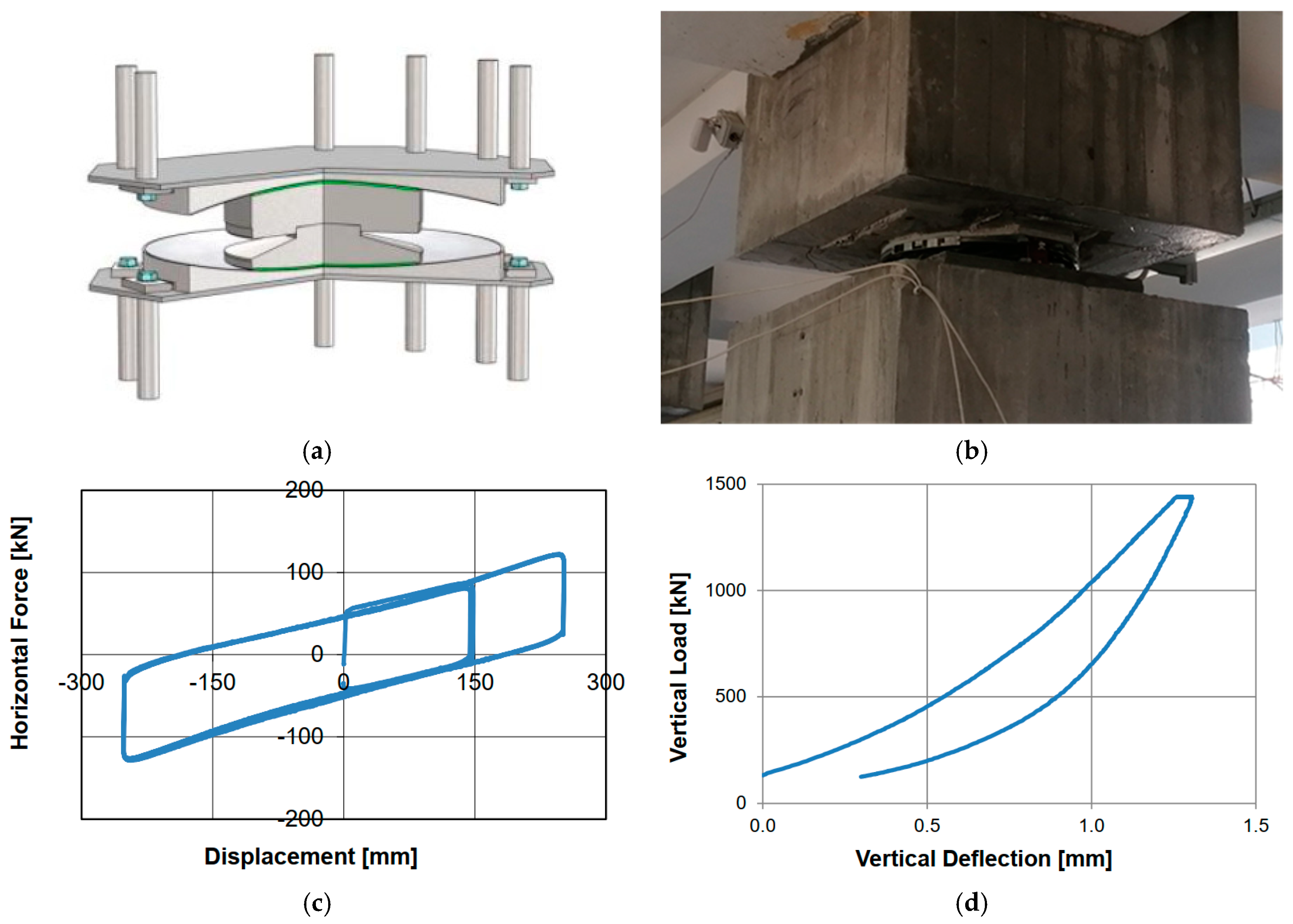
For the presently reported application, sliding isolator devices, as in Figure 3a, i.e., friction pendulum type, are used for seismic retrofit of the investigated building (Figure 3b). According to the technical documentation of the producer [24], these seismic devices (PS 1400/600 type) are characterized by an equivalent radius of 2300 mm and can offer a design friction coefficient of up to 4.7%. They are designed to accommodate a lateral displacement of 250 mm in seismic conditions (and up to 300 mm). Their typical constitutive behaviour under horizontal forces can be seen in Figure 3c, as obtained from dedicated experimental certification [25], according to [26]. Figure 3d shows their typical experimental response under vertical loads [25]. The major advantage of sliding bearings, as in Figure 3, is that they support the weight of the primary structure on a bearing that rests on a sliding interface [27,28]. As such, maximum benefits and protective contributions (in terms of the dynamic response of the retrofitted system) can be expected under seismic events.
For the present application to the Frangipane school building, the choice of seismic devices and retrofit intervention based on base isolation was mainly dictated by the primary need to avoid structural interventions on the load-bearing elements of the upper floors. Also, the specific type of devices, as in Figure 3, was selected on the base of preliminary considerations about the layout of a case-study building.
In the last few years, the upper stories of the examined building have been, in fact, the object of several interventions and renovation activities (i.e., for the electrical system, but also for video surveillance tools, fire prevention and internet networks), as well as the object of intervention for replacement of original fixtures (doors and windows). Therefore, a possible seismic retrofit intervention based on necessary structural reinforcements for load-bearing components (such as concrete beams and pillars), as well as the possible installation of supplementary brace systems (for improving the global performance of the building to horizontal design loads), would have resulted in a major disassembly or even destruction for most of the above-renovated facilities/services and refurbishment activities.
Finally, sliding devices, as in Figure 3, were preferred to other technological solutions because torsion motions of the primary structure are usually minimized, given that the centre of stiffness of the isolators automatically coincides with the centre of mass of the supported system. The friction pendulum bearings have strong resetting and self-limiting capabilities, low sensitivity and high stability to the seismic excitation frequency range, and excellent energy dissipation capacity [29].

3. The Case Study of Frangipane School

3.1. General Description

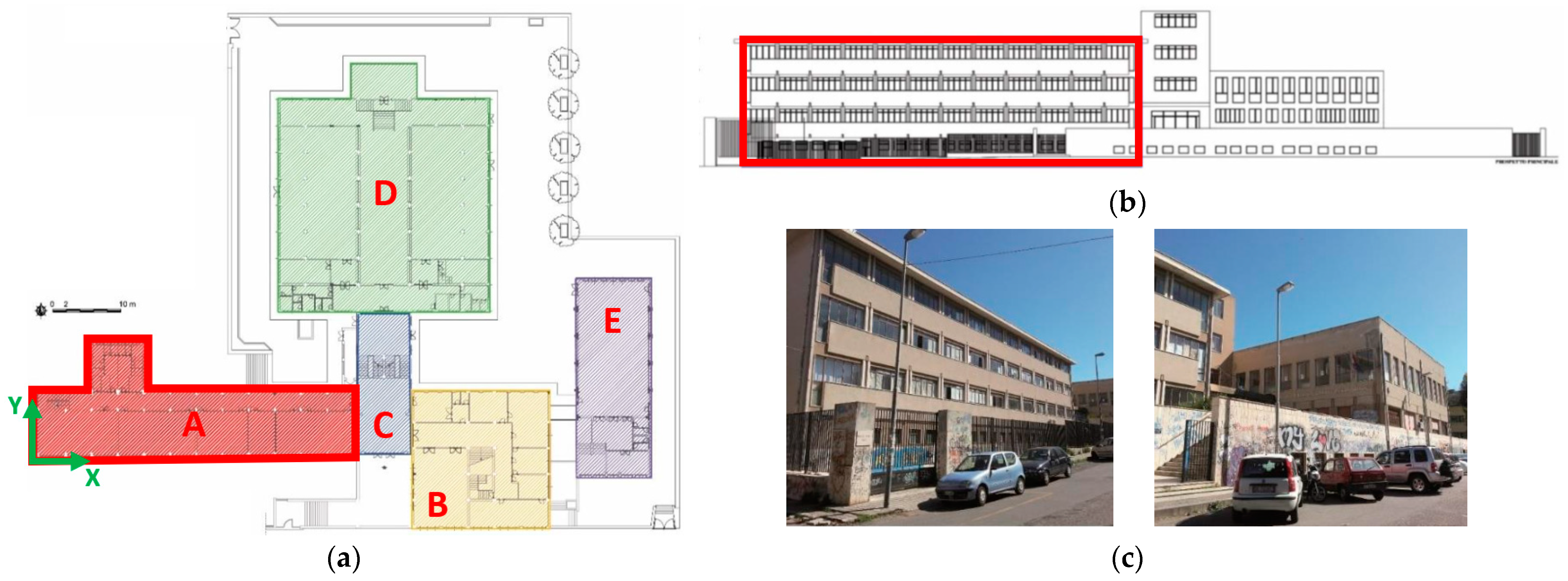
This examined school building was realized in the 1960s in the Southern side of the historical city centre of Reggio Calabria and designed according to a code of the first generation (Regio Decreto Legge 25 Marzo 1935, n. 640, [30]). The main class of use of adjacent buildings, also built up in the 1960s–70s can be classified as “residential” and “commercial”, with a majority of multi-story RC structures with up to 4 or even 10 elevation levels from the foundation. Overall, the Frangipane school consists of 5 major parts with regular shapes, noted as “Corpo A” to “Corpo E” in Figure 4a.
Among others, the attention of the present investigation is focused on the so-called “Corpo A”, which is highlighted in Figure 4 and is currently used to host the majority of students during daily activities, with a major risk for occupants in case of a seismic event.
The selected building portion is characterized by four elevation levels and covers approximately 470 m2/story, for a total of around 1870 m2. Most importantly, for the current investigation, the “Corpo A” system is characterized by an independent structural behaviour from the rest of the school building, thanks to the presence (even not adequate) of a seismic joint at the interface with “Corpo C”. The presently reported retrofit intervention, in this regard, also consisted of the increase of the seismic joint thickness (from about ≈3 cm of the original system up to 42 cm with the current intervention) in order to ensure the building system accommodates the lateral displacement of seismic devices and the cumulative effect of inter-story drift amplitudes for “Corpo C”.
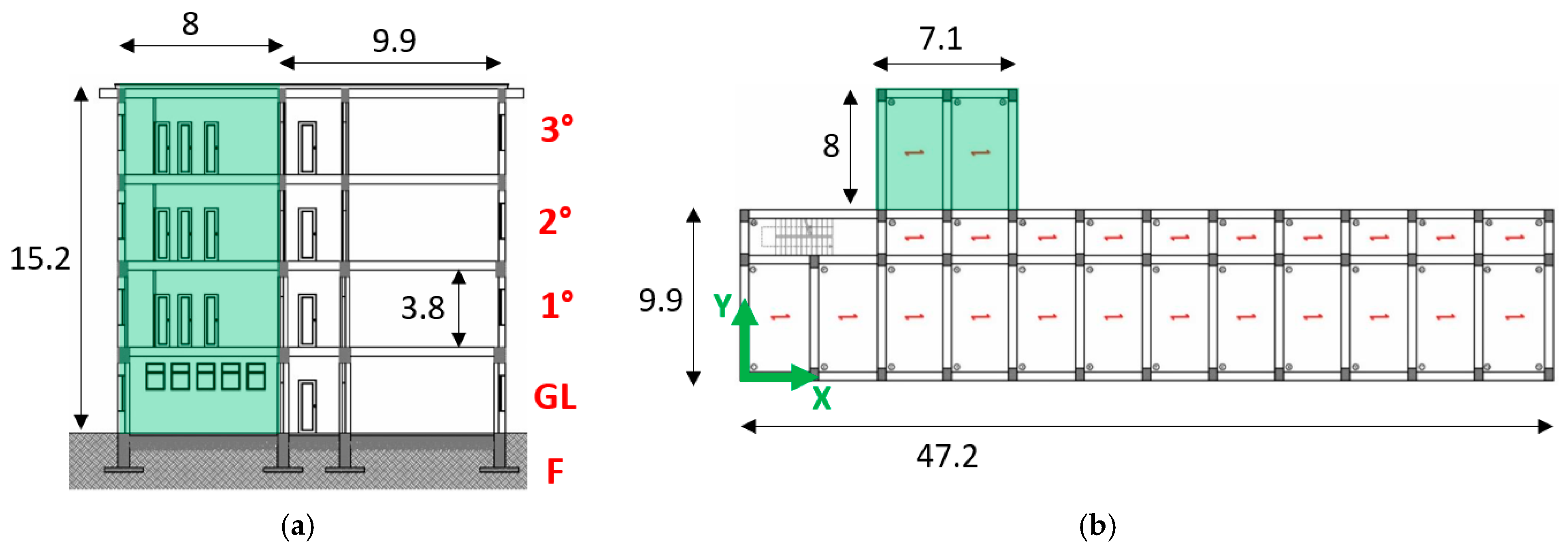
The examined “Corpo A” sub-system is characterized by a mostly regular distribution of load-bearing members through the elevation. The building has a total height of 15.2 m, with an inter-story height of 3.8 m each (Figure 5a). The plan layout is characterized by a total dimension which covers a length of 47.2 m and a maximum width of 9.9 m. In terms of seismic retrofit purposes, it has to be noted that the system suffers from a high length-to-width ratio in the plan, and this aspect was taken into account in terms of possible sensitivity to torsional motions while choosing and detailing the intervention and the seismic devices as in Figure 3. As a minor extension, see Figure 4a and Figure 5b, there is an additional portion of the sub-structure, on the North side, with plan dimensions of 7.1 × 8 m, a total height of 15.2 m and an inter-story height of 3.8 m each.
In total, for the longitudinal direction (x-direction) of the building system, a number of 13 frames is used to create the 3D structure. These frames are equally spaced at 3.86 m along the maximum size of the building system. The exception is represented by external frames (on the East and West sides of the building system), which are characterized by a maximum spacing of 4.15 m.
In the transversal direction (y-direction), RC frames are reduced to 3 and irregularly spaced on the plan layout of the 3D volume, that is, with a spacing of 6.8 m, 2.7 m and 7 m, respectively. Note that the minimum space of 2.7 m follows the destination of use of indoor spaces and corresponds to the main corridor of the school. Inter-story and roof slabs, finally, are realized with 35 + 5 cm thick, unidirectional resisting cross-section, and oriented as reported in Figure 5b. Table 1 summarizes the cross-sectional dimensions of pillar and beam-type resisting RC members, grouped by the story, while additional selected geometric details are proposed in Figure 6.
Table 1. Cross-section of load-bearing members. F = foundation level; GL = ground level.
StoryPillars [cm]Beams [cm]
F-50 × 150
GL50 × 7050 × 70
40 × 7040 × 70
40 × 7030 × 70
30 × 6030 × 60

3.2. In-Field Inspection and Experimental Characterization of Materials

During the preliminary stage of presently reported interventions, a large set of in-field and laboratory experiments has been carried out to characterize the actual mechanical properties of steel and concrete composing the load-bearing frame members, as well as to achieve appropriate knowledge on constructional details, as required by current technical standards [31,32]. The structural analysis and seismic retrofit assumptions were based on a “Knowledge Level” (KL, also known as LC) equal to 2 (“LC2”) of both the structural system and materials properties. Such a result was achieved based on the following:
  • a preliminary historical/archivistic research on documentation about structural details of the system;
  • an in-field geometrical inspection of load-bearing features for the building system object of study;
  • and an extended set of in-field experimental investigations aimed at capturing the composition of RC members in terms of rebars and stirrups arrangements, but also to quantify the actual mechanical properties of steel and concrete materials.
Accordingly, the investigation included the following:
  • Magnetometric inspections to detect the number, diameter, and position of steel rebars and stirrups (for a total of 100 measurements at various levels of the building). An example is proposed in Figure 7a;
  • inspection of the foundation system (Figure 7b);
  • inspection of steel rebars in beams and pillars (Figure 7c);
  • endoscopic inspection of inter-story floors;
  • extraction of samples for concrete and steel mechanical characterization (Figure 7d,e and Table 2).
Table 2 summarizes the average values of compressive strength for concrete, as obtained from a total of 28 cylindrical specimens (with d/l = 2 the diameter-to-length ratio), which have been extracted from various levels of the building, both for beams and pillars. Experiments on concrete have been carried out according to EN 12504-1 [33].
Similarly, the material characterization carried out on 20 samples of steel rebars resulted in an average tensile strength of fs,y = 371.86 MPa for yielding and fs,u = 552.91 MPa at failure.
Table 2. Mechanical properties of concrete, based on in-field and laboratory experiments (average values).
BeamsPillars
Storyfc,m [MPa]fc,m [MPa]
F25.81-
PT26.5420.52
18.1011.00
21.399.37
17.627.78

4. Finite Element Numerical Analysis

The examined structural system was numerically investigated with the support of Midas GEN commercial software [34]. More precisely, a set of mono-dimensional (1D) beam elements was used to reproduce the structural members, as in Figure 5 and Table 1. The mechanical characterization of materials was based on the in-field experimental investigation summarized in Section 3.2. At first, the state-of-art of the building was assessed under seismic events (MU model, in the following). Seismic isolators, as in Section 2, were successively introduced at the top of pillars, at the foundation level, to improve their overall capacity to mitigate possible input earthquakes (MIS model, as discussed in the following). Overall, the investigation included a set of linear modal analyses (LMOD), as well as a series of non-linear static analyses (PO) and non-linear dynamic simulations (NDYN) on both MU and MIS model assemblies.

4.1. Modelling Strategy

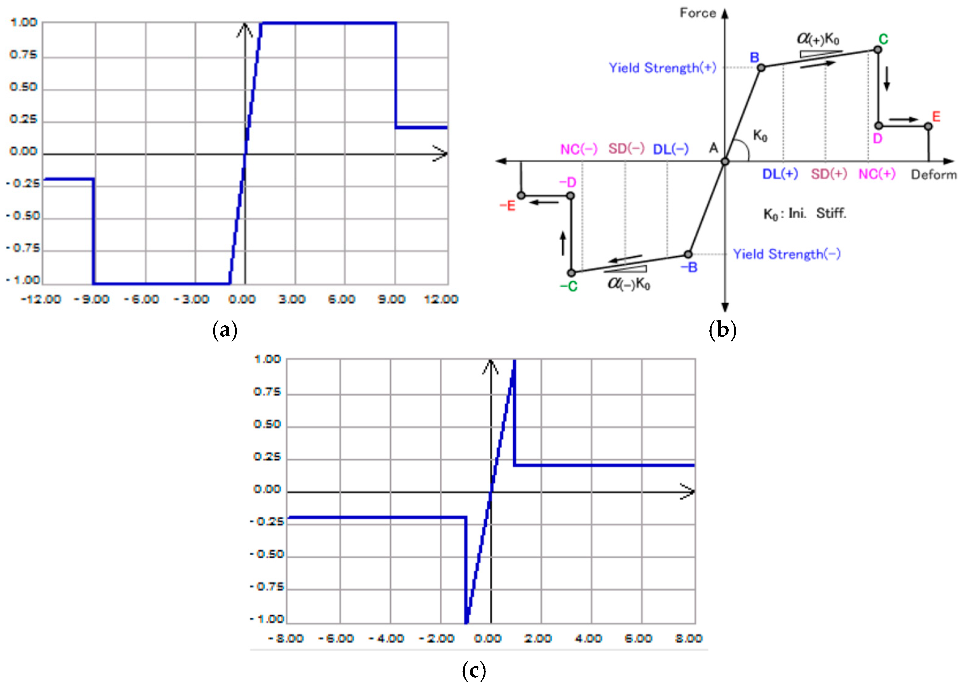
The modelling strategy consisted of the use of 1D beam elements with nominal geometrical properties according to Table 1 and lumped plasticity hinges to include the effect of possible degradation and damage evolution. More precisely, the mechanical characterization was carried out based on Eurocode 8 (EC8) [35] and as in Figure 8.
Compared to literature and practice assumptions, a basic and conventional but consolidated modelling approach was used for the Frangipane school building in terms of load-bearing members and seismic devices, which have both a primary role for seismic assessment purposes.
According to several research efforts, the use of 1D elements and lumped mass plasticity models for RC frame structures in seismic conditions is rather efficient in computational cost and robust in terms of the accuracy of results. Comparative non-linear numerical analyses reported in [36] for a five-story RC frame showed, for example, a rather good correlation of seismic performances for FE models based on lumped plasticity or finite length hinges approaches. The results of extended parametric analyses proposed in [37] for FE models based on lumped plasticity or distributed plasticity formulations, on the other side, gave evidence of scattered predictions in terms of the inter-story drift ratio and maximum base moment from a comparison of plasticity formulations on selected buildings. When possible, however, empirical expressions and constitutive laws calibrated to experimental data should be preferred to conventional plastic models, which are already implemented in commercial codes [38].
Figure 8. Lumped plasticity model approach: (a) moment-rotation constitutive law according to EC8; (b) quadrilinear moment-rotation constitutive law; (c) constitutive shear law.
Applsci 12 12894 g008
Similar attention should also be spent on the mechanical characterization of seismic isolation devices and the use of experimentally derived mechanical features for seismic analyses [5]. In the specific application of friction devices as in the present study, literature efforts proved that both static and dynamic friction phenomena, which are intrinsic to selected devices (but disregarded for the static component in most commercial codes), could have additional effects on predicted seismic response of the RC frame components [27]. Such a calibration process—for plasticity formulations and static friction terms—would result in additional precision for the behaviour assessment of load-bearing elements in ordinary RC buildings but structural systems in general, which are located in seismic areas, including base isolation technologies.

4.2. Vibration Modes of MU System (LMOD Analysis)

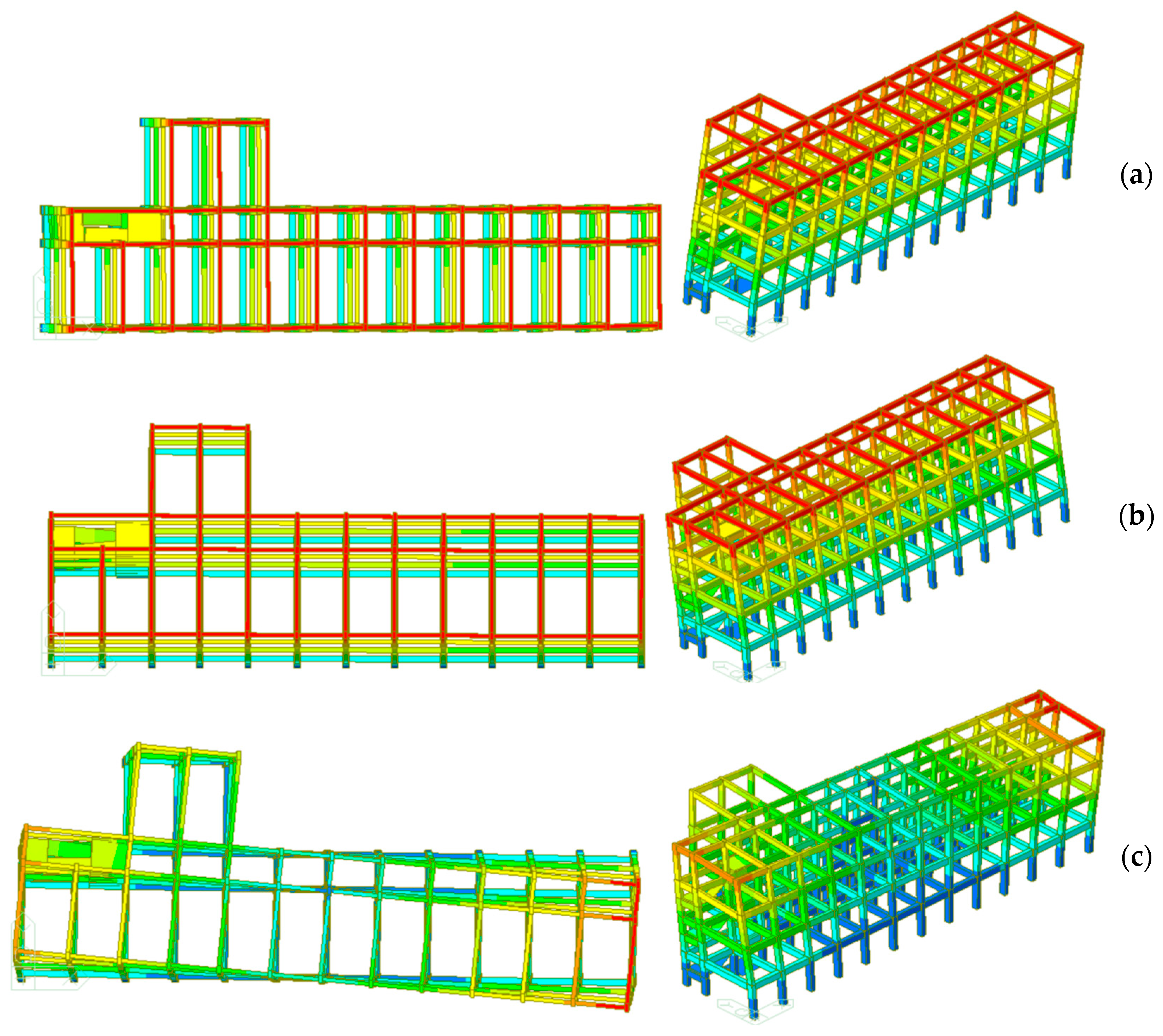
The first 12 vibration modes were first numerically estimated for the Frangipane structural system. The most flexible direction of the system was found to coincide with the longitudinal one (x direction), with a fundamental vibration period of T1 = 0.55 s and a participant mass in the order of M = 75.02%. It is worth noting that the calculated participating mass also denotes a mostly longitudinal translational vibration mode of the structure as a whole, with minimum rotational mass contribution (around 0.12%).
Similar trends were observed for the second vibration mode, which is characterized by rather clear translational vibration in the transversal (y) direction of the system and a rather null mass contribution participating in rotation (less than 0.13%). The third vibration mode, finally, was detected in a purely torsional shape, with around 77% of participating mass in the rotational term. For the fourth (translational in the x direction, fifth (translational in the y direction) and sixth (rotational around z direction) vibration modes, the participating mass was quantified in the order of 10–11% each. This means that with the first six vibration modes of the system, the minimum of 85% of participating mass required by EC8 was properly satisfied. Detailed mass contributions for vibration modes are summarized in Table 3, while Figure 9 reports the modal shapes of the system.
Table 3. Summary of vibration periods and participating mass contributions for the first 12 vibration modes of MU system (LMOD analysis, Midas).
Tran-xTran-yRot-xRot-yRot-z
Mode
Order
T
[s]
M
[%]
Sum
[%]
M
[%]
Sum
[%]
M
[%]
Sum
[%]
M
[%]
Sum
[%]
M
[%]
Sum
[%]
10.554275.018975.01890.00520.00520.00020.00020.00030.00030.11870.1187
20.46480.004575.023376.818776.82390.00030.000500.00030.01410.1328
30.45150.111875.13520.027776.85160.00040.00090.00010.000576.445476.5782
40.251710.294685.4298076.85160.00150.00240.00970.01010.002376.5806
50.1761085.42988.853685.70520.1060.108400.01023.793880.3744
60.16970.000185.42994.033289.73840.01770.12610.00010.01038.816889.1912
70.15168.545393.9752089.73840.0080.13420.31110.32140.002189.1933
80.11145.79899.77320.004489.74290.01320.14730.36080.68220.020489.2137
90.10520.018999.79214.40994.15191.08361.2310.00320.68542.986592.2002
100.10310.006699.79872.556996.70880.09251.32350.00730.69274.233206.4334
110.0771099.79870.000796.70950.01651.340.51961.21230.000196.4335
120.07380.011999.8107096.70950.00791.34790.17691.38920.046596.4801

4.3. Seismic Demand and Capacity Assessment of MU System (PO Analysis)

Under seismic events, the capacity of the MU system was preliminary based on the PO analysis of the structure. Regarding the application of static equivalent lateral loads, most importantly, a set of configurations was taken into account for the two principal directions of the building, namely the longitudinal one (x-direction) and the transversal one (y-direction). Figure 10 summarizes the reference coordinate system.
Also, two different conventional distributions were properly considered on the elevation of the building, namely a first mode proportional distribution (MS, in the following) and a uniform distribution of lateral loads on the height of the structural system (UAS, in the following):
  • MS x+: first modal shape distribution, positive longitudinal direction (x+) of equivalent static lateral loads;
  • MS x−: as above, with negative direction;
  • MS y+: as above, with positive transversal direction;
  • MS y−: as above, with negative direction;
  • UAS x+: uniform distribution, with positive longitudinal direction;
  • UAS x−: as above, with negative direction;
  • UAS y+: as above, with positive transversal direction;
  • UAS y−: as above, with negative transversal direction.
Figure 10. Schematic loading configurations for PO analyses: (a) first mode proportional distribution (MS type) and (b) uniform distribution (UAS type).
Applsci 12 12894 g010
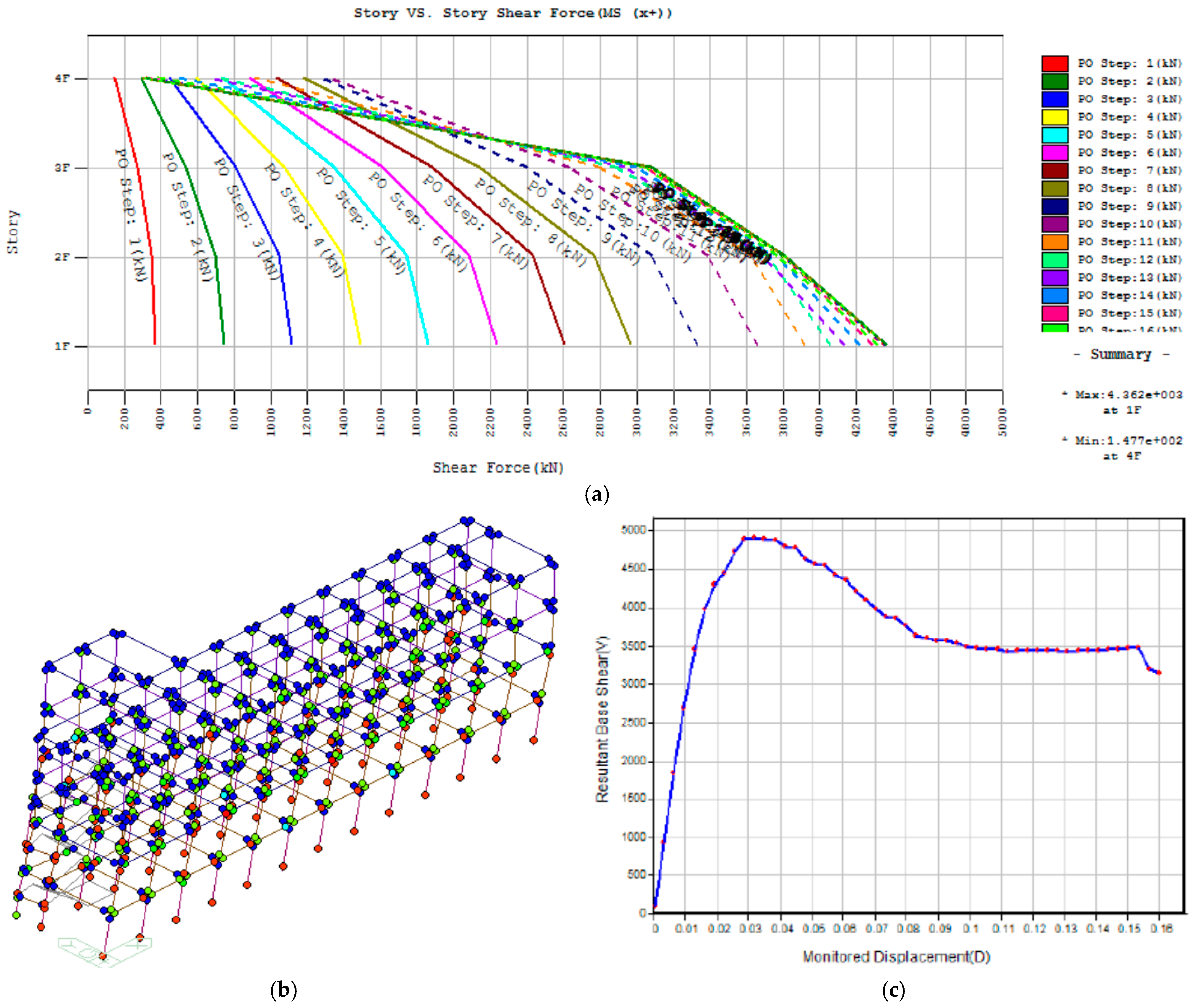
Selected results can be seen in Figure 11. More precisely, Figure 11a shows the typical distribution of shear story forces extracted from the MU model at various PO steps of the loading protocol.
In this regard, see Figure 11b; the global analysis of the system gave evidence of overall composite system behaviour with a lack of soft-story phenomena. Similarly, the numerical analysis also gave evidence of limited seismic capacity to the original configuration of the system.
Figure 11. Seismic capacity assessment of MU model, based on PO analysis (Midas): (a) shear distribution at different story levels for selected PO steps (MS x+ loading case); an example of (b) lumped plasticity damage (UAS x+) and (c) measured residual base shear as a function of monitored top displacement (MS y+).
Applsci 12 12894 g011

5. Retrofit Intervention (MIS Configuration)

5.1. Retrofit Strategy
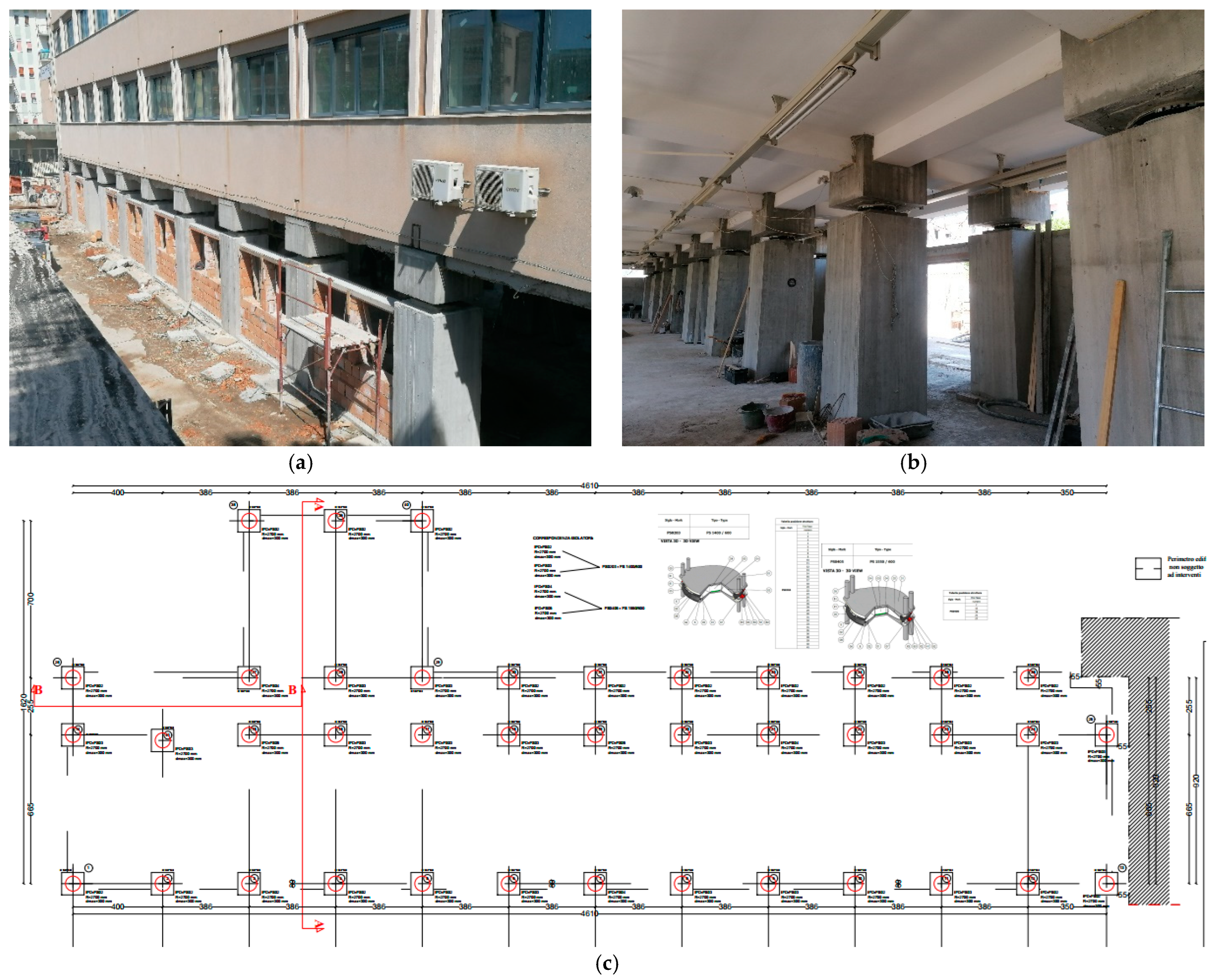
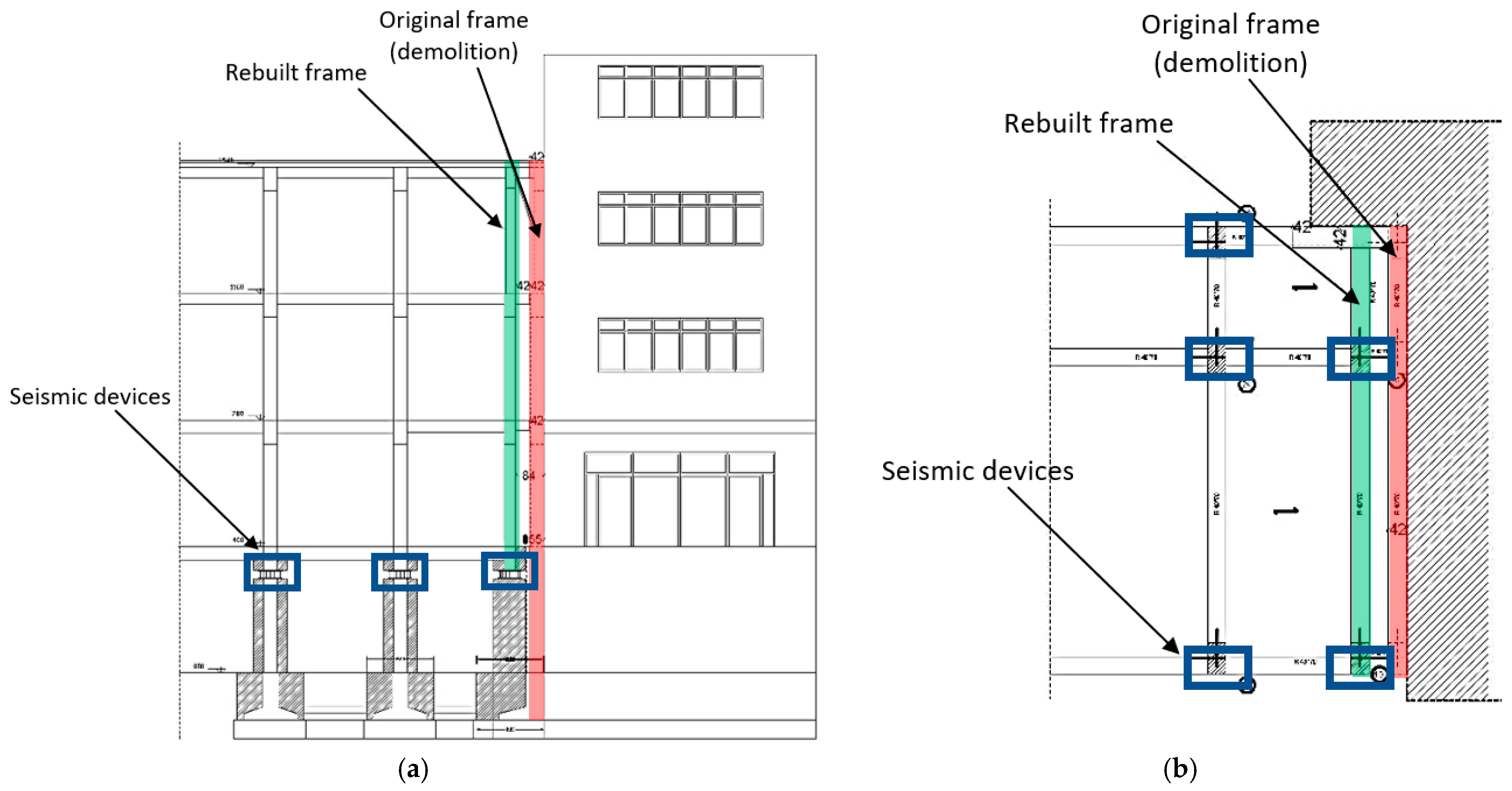
To improve the seismic response of examined building system, a number of 40 seismic devices, as in Figure 3, have been installed according to Figure 12. Figure 12a,b shows the typical layout for the in-field positioning of seismic devices, while Figure 12c gives evidence of the top-view installation plan.
In addition, as a key step of the overall retrofit intervention, the building capacity to accommodate the lateral design movement of seismic devices (max 300 mm, according to technical data sheets), the technical joint between the “Corpo A” and “Corpo C” systems was increased up to a total of 420 mm.
This result was achieved by demolishing the last 5-story frame of the original building system and by rebuilding it 840 mm back from its original position, as reported in Figure 13.
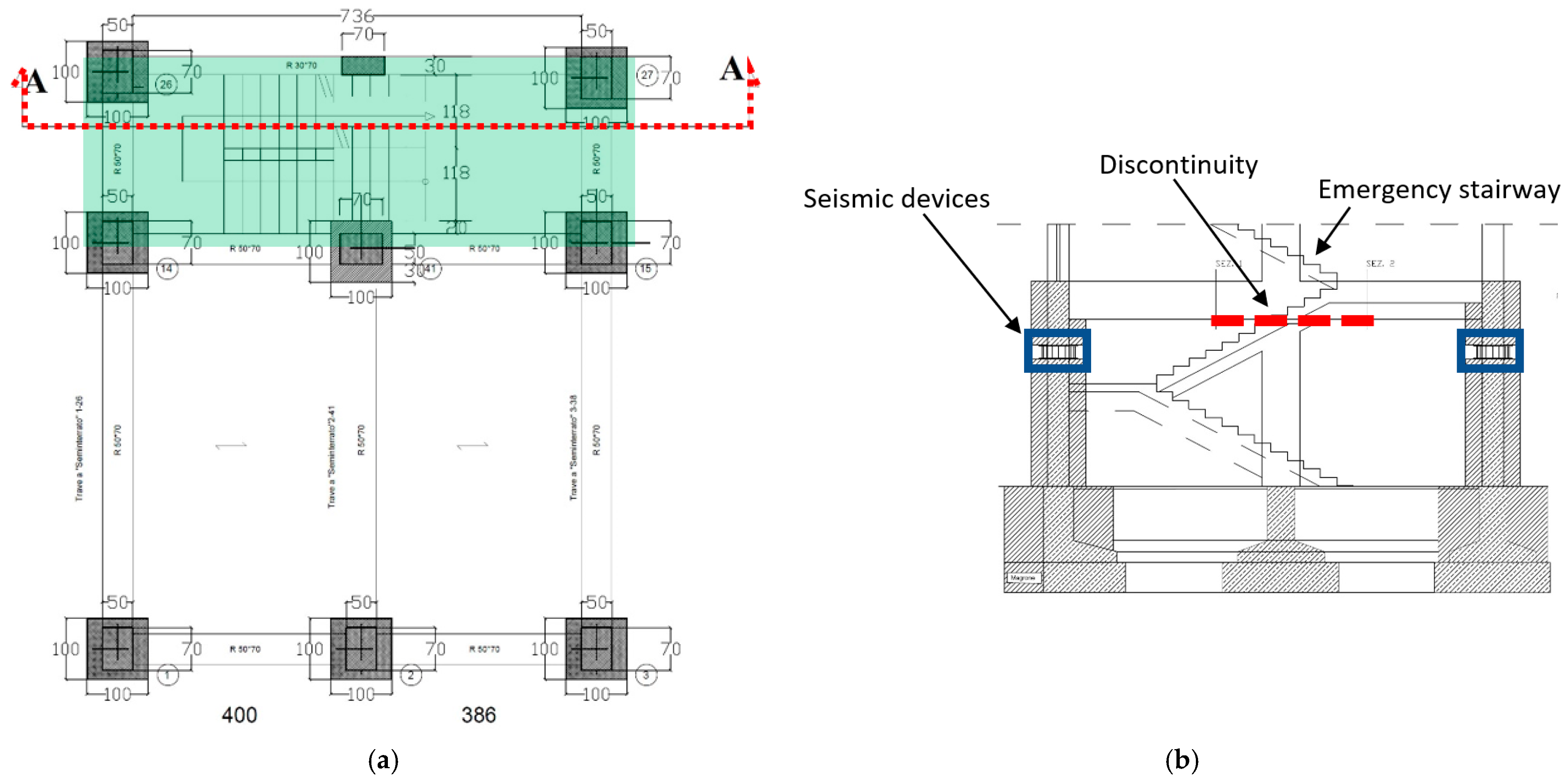
Finally, careful attention was paid to vertical load-bearing members like the stairway reported in Figure 14. In order to facilitate the lateral deformation of the isolated building system with seismic devices, the emergency stairway in Figure 14 was partially interrupted at the foundation level. For the upper inter-story levels, the stairway continuity was established again while ensuring the lateral displacement capacity of seismic devices.
Figure 12. In-field installation of seismic devices (40 in total): (a) external view and (b) internal view, with (c) detailed plan view from technical drawings (dimensions in cm).
Applsci 12 12894 g012
Figure 13. Detail of seismic joint: (a) vertical cross-section and (b) plan view.
Applsci 12 12894 g013
Figure 14. Detail of seismic joint in the region of emergency stairway: (a) plan view (dimensions in cm) and (b) vertical cross-section (detail of foundation level).
Applsci 12 12894 g014

5.2. Seismic Performance Assessment

The site seismic hazard was considered for a reference period VR of 75 years (Nominal Life VN = 50 years and Coefficient of Use CU = 1.5), in accordance with [31,32].
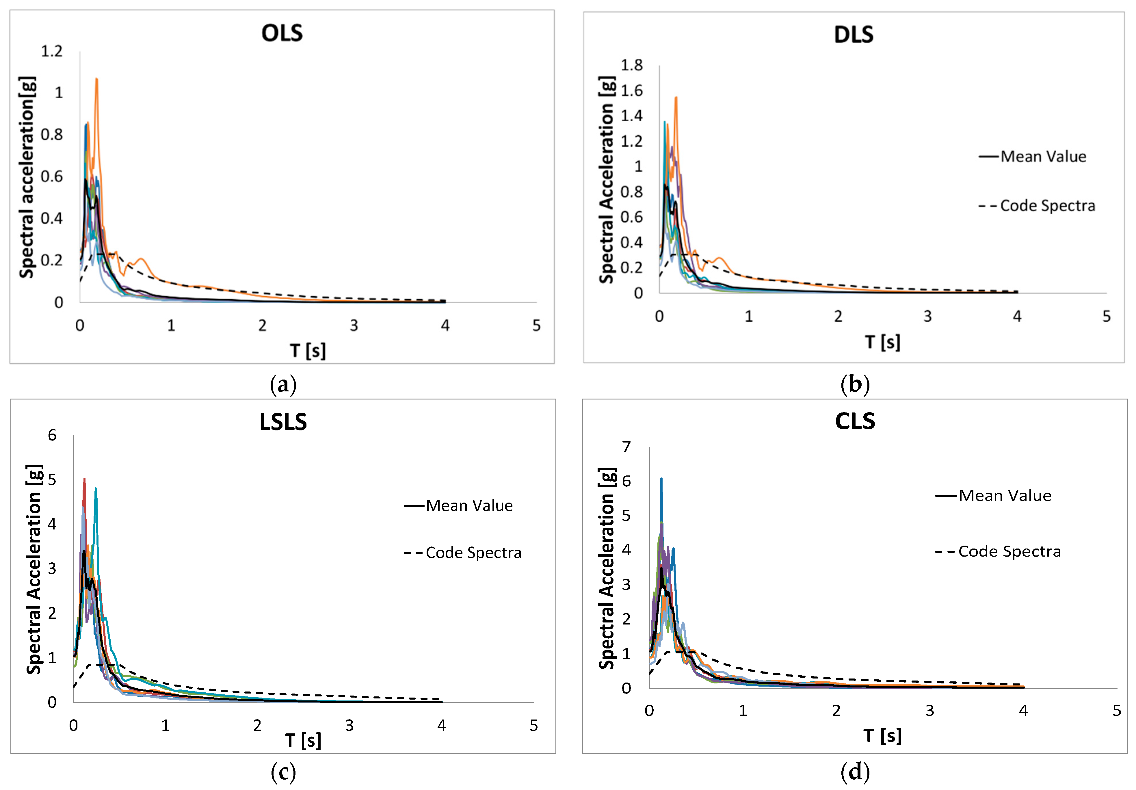
As such, the following Limit States were considered: Operativity Limit State (OLS), Damage (DLS), Life-Safety (LSLS) and Collapse Limit State (CLS). In particular, being the examined structure associated with Class III, according to the provisions of LR Calabria n. 35 [33], it was first necessary to calculate the local seismic response of the construction site. For each Limit State, reference spectra have been thus calculated based on the online available REXEL data sheet by assuming a total of 7 accelerograms for each Limit State [39]. In the selection of the accelerograms, earthquake events with a magnitude between 5 and 6.5 were taken into account, with an epicentral distance between 5 and 25 km and a duration between 15 and 25 s. The so-calculated response spectra can be seen in Figure 15.
In accordance with [31,32], both the superstructure and substructure were numerically described in Midas software as systems with non-dissipative linear elastic behaviour, while the isolation system was modelled as a linear equivalent one (see Figure 16).
In detail, Figure 16 shows the top and axonometric views of the studied building, with evidence of fundamental longitudinal, transverse and torsional mode shapes, respectively. In this case, it is worth noting that 99% part of the total mass of the building (cumulative effective modal mass) is represented, which corresponds to the 100% part of the superstructure mass.
Overall, in accordance with section 7.10.5.2 in [31], the following conditions were met:
(a)
the equivalent stiffness of the isolation system was measured as greater than the 50% part of the secant stiffness for cycles with displacement equal to a 20% part of the reference displacement;
(b)
the equivalent linear damping of the isolation system was less than 30%;
(c)
the force-displacement characteristics of the isolation system must not be subject to deviations of more than 10% due to variations in the deformation velocity, the vertical action on the devices;
(d)
the increase of the strength in the isolation system for displacements between 0.5 times the design displacement and its maximum amplitude must be at least equal to 2.5% of the total weight of the superstructure. This request involves the use of a radius of curvature limited to 20 times the value of the project shift.
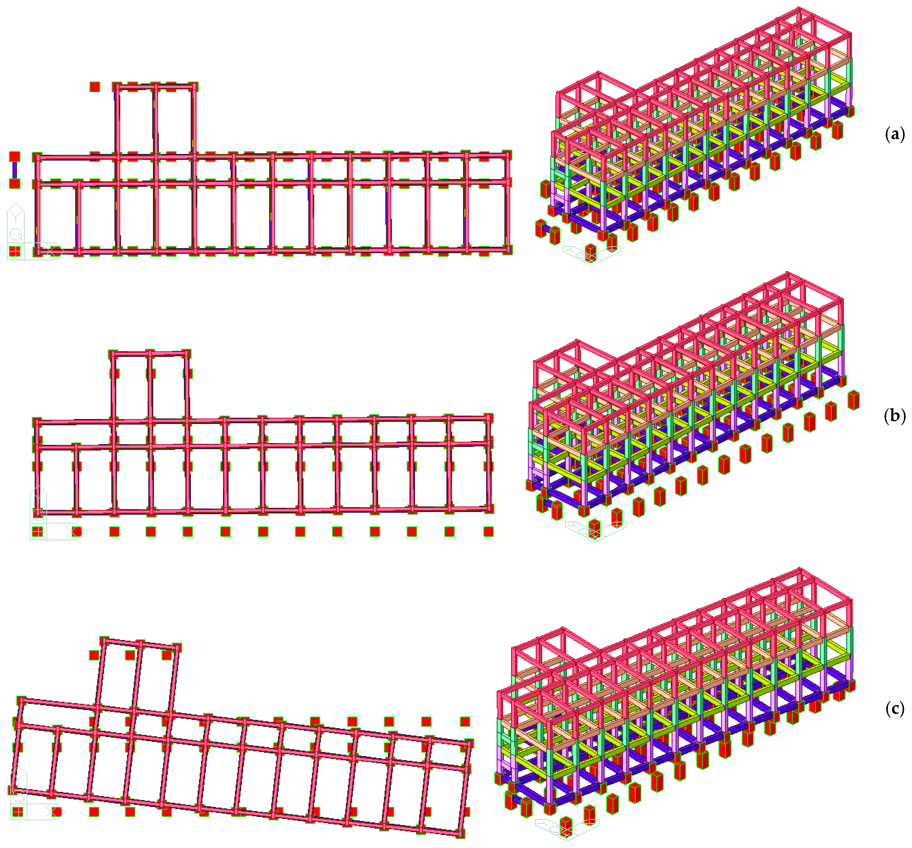
Figure 16. Fundamental vibration modes of the MIS system (Midas): top view and axonometric view: (a) longitudinal; (b) transverse; (c) torsional mode shapes.
Applsci 12 12894 g016
As is evident in Figure 16, the superstructure clearly behaves like a rigid body (T1,IB = 2.24 s the vibration period of the isolated system). The maximum displacement calculated for the superstructure was estimated at less than 280 mm, for CLS.
According to national code [31,32], the maximum displacement at CLS for the “Corpo C” system (i.e., a non-isolated building— D m a x , N B , C L S ) can be thus calculated as:
d m a x , N B , C L S = H N B 100 · a g g · S = 15.20 100 · 0.421 · 1 = 0.0639   m = 64   mm
in which:
  • ag is the maximum horizontal acceleration at the considered Limit State;
  • g is the acceleration due to gravity;
  • S is a coefficient that takes into account the category of subsoil and topographical conditions; and
  • HNB is the height of “Corpo C”.
Considering that the maximum displacement of the isolated building, “Corpo A”, was predicted in D m a x , I B ,   C L S = 280 mm, for safety reasons, the seismic joint was assumed to be equal to:
d m a x , C L S = 420   mm > d m a x , N B , C L S + d m a x , I B ,   C L S = 64 + 280 = 344   mm
In terms of seismic performance assessment, it is important to underline that—as also required by the Italian reference standard—an accidental eccentricity with respect to the actual position was assigned to the centre of mass in order to take into account the spatial variability of seismic motion, as well as any uncertainties in seismic analysis.
In fact, for buildings where more accurate determinations are not possible, it is recommended that accidental eccentricity in any direction should not be considered less than 0.05 times the average size of the building, which is measured perpendicular to the direction of application of the seismic action. For the present investigation, it is evident that the calculated d m a x , I B ,   and   C L S displacement amplitude is greater than the displacement undertaken by the centre of mass.

5.3. Seismic Demand Assessment

In conclusion, the comparison between the seismic performance of the fixed-base, non-isolated (NB) building system and the base isolated (IB) Frangipane school building system under seismic actions was further quantified in terms of maximum seismic demands in load-bearing RC members.
The numerical analysis for the previously defined seismic combinations gave evidence of typical behaviours that can be overall summarized in structural performances of the isolated system characterized by:
  • a significant reduction in stress characteristics in terms of bending moment and shear design actions due to input seismic loading for all the load-bearing components of the RC superstructure;
  • but also a significant reduction in the expected inter-story drift, with most of the horizontal displacement demand due to input seismic actions measured at the level of the base isolators rather than on the elevation of the building system itself.
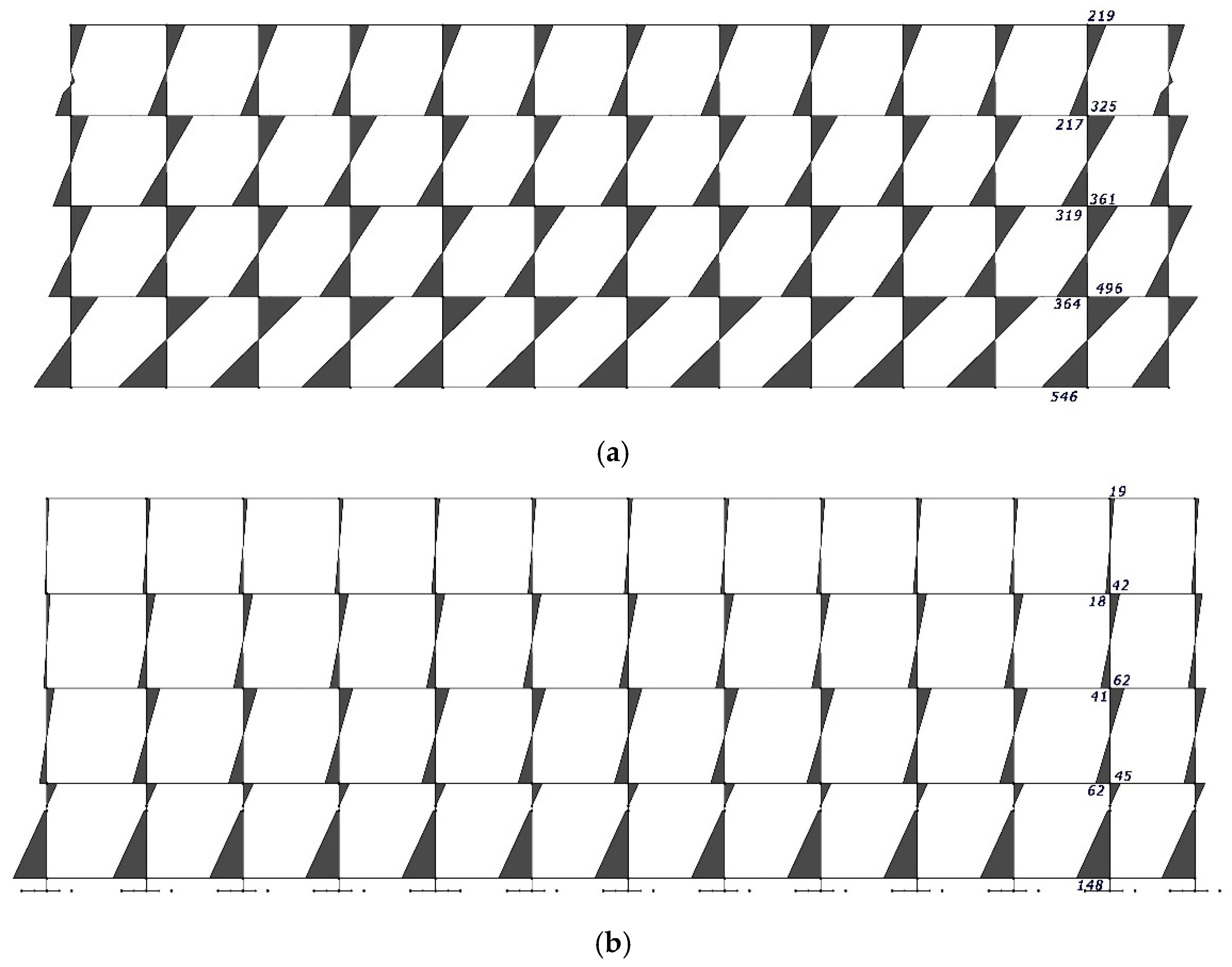
Such an outcome and structural behaviour in seismic conditions for the IB system compared to the NB configuration can also be perceived from the numerical examples reported in Figure 17 and Figure 18.
In Figure 17, the typical distribution of bending moment in RC columns can be seen for longitudinal RC frames in the x-direction. It is worth noting, as also expected that the typical bi-triangular distribution is qualitatively similar for the two configurations. Besides, the presence of seismic isolators manifests in a bending moment reduction, both at the ground level and at the upper story levels, which is in the range of 70–80%, compared to the NB system (see Figure 17b).
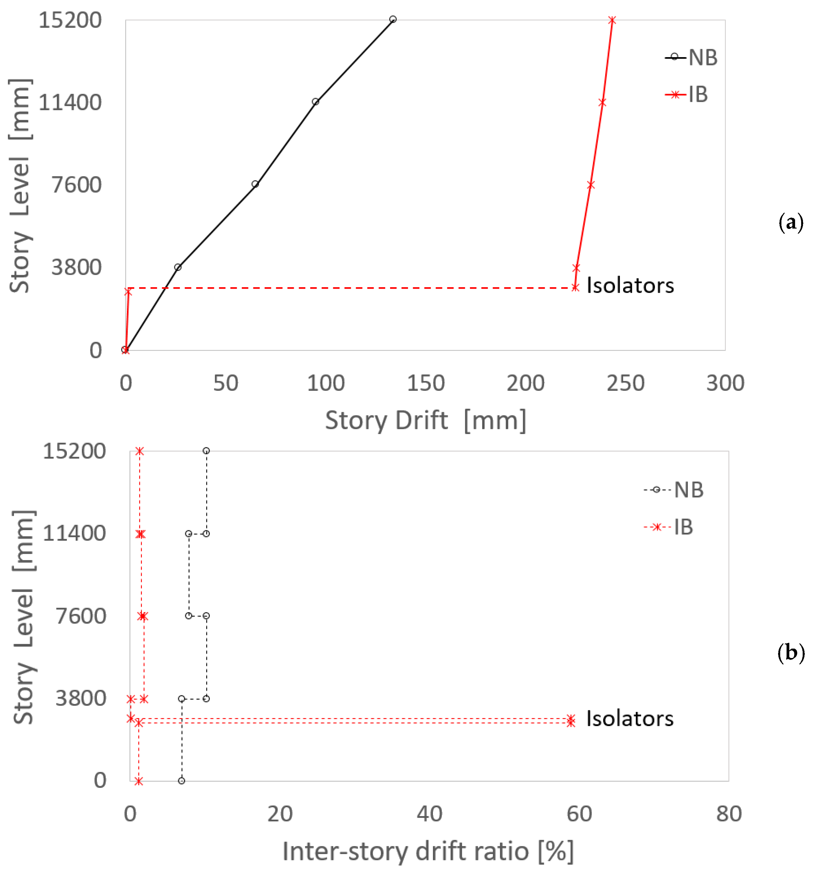
In terms of drift demand, further numerical comparisons are proposed in Figure 18, with evidence of the major modification in the structural behaviour of NB and IB systems, respectively. In this case, attention is given to the story drift demand and inter-story drift ratio as a function of the story level of each centre of mass.
Figure 17. Example of numerically calculated bending moment in RC columns for longitudinal frames in the x-direction (Midas): (a) non-isolated (NB) or (b) isolated (IB) building system (values in kNm).
Applsci 12 12894 g017
From Figure 18a, it is thus worth noting that the NB configuration is typically characterized by a story drift demand which is proportional to the first vibration shape of the structural system (see also Figure 9a). As far as the drift demand is addressed for the building system equipped by base isolators (IB), it is possible to note that most of the measured horizontal displacement is lumped at the level of isolators themselves, and the story drifts demand for the superstructure is less pronounced. Such an observation confirms the mostly rigid-body motion of the superstructure under seismic events and is in line with the fundamental vibration shape reported in Figure 16a.
When the inter-story drift ratio is also examined for both configurations, typical results, as in Figure 18b can be found.
For the IB configuration, the inter-story drift demand was generally measured in the range of −70–90% of the corresponding demand for the NB system, with most of the inter-story demand at the levels of seismic isolators.
Figure 18. Example of numerically calculated drift for the centre of mass of the non-isolated (NB) or isolated (IB) building system (Midas): (a) story drift and (b) inter-story drift ratio.
Applsci 12 12894 g018

6. Conclusions

For decades, seismic devices have been known to efficiently improve the structural performance of buildings and structures exposed to earthquakes. In this paper, a recent practical application of seismic isolation devices for the protection of an existing RC building has been presented. The attention was focused on a case-study school building, the Frangipane School, which is located in Reggio Calabria (Italy) and was originally built in the 1960s—based on technical documents of the first generation—to sustain vertical design loads only. Given such a basic design assumption, its load-bearing capacity (especially towards seismic events) was presently severely affected and not in line with actual seismic classifications and specifications for the Italian territory, thus requiring urgent retrofit intervention.
Among various technological solutions, the attention of the present design application was dedicated to seismic sliding devices (friction pendulum type), which are seismically efficient (like many others) and take major advantage of energy dissipation from friction phenomena. Most importantly, like base-isolation approaches in general—they allow for avoiding major retrofit interventions on the primary load-bearing components of the 3D structure to retrofit. Also, the selected sliding devices allow for minimizing torsion motions of the primary structure, given that the centre of stiffness of the isolators automatically coincides with the centre of mass of the supported system. As such, they are particularly recommended for buildings with plan layouts which—as the Frangipane School—suffer from high length-to-width ratio and thus possible torsional motions.

Author Contributions

This research paper results from a joint collaboration of all the involved authors. R.P., R.A.D.L. and C.B. contributed to the paper drafting and review. All authors have read and agreed to the published version of the manuscript.

Funding

This research received no external funding.

Institutional Review Board Statement

Not applicable.

Informed Consent Statement

Not applicable.

Data Availability Statement

Data will be shared upon request.

Conflicts of Interest

The authors declare no conflict of interest.

References

  1. Warn, G.P.; Ryan, K.L. A Review of Seismic Isolation for Buildings: Historical Development and Research Needs. Buildings 2012, 2, 300–325. [Google Scholar] [CrossRef] [Green Version]
  2. Ibrahim, R.A. Recent advances in nonlinear passive vibration isolators. J. Sound Vib. 2008, 314, 371–452. [Google Scholar] [CrossRef]
  3. Kelly, J.M. Aseismic base isolation: Review and bibliography. Soil Dyn. Earthq. Eng. 1986, 5, 202–216. [Google Scholar] [CrossRef]
  4. Kelly, J.M. Seismic isolation systems for developing countries. Earthq. Spectra 2002, 18, 385–406. [Google Scholar] [CrossRef]
  5. Bedon, C.; Morassi, A. Dynamic testing and parameter identification of a base-isolated bridge. Eng. Struct. 2014, 60, 85–99. [Google Scholar] [CrossRef]
  6. Sorace, S.; Terenzi, G.; Bitossi, C.; Mori, E. Mutual seismic assessment and isolation of different art objects. Soil Dyn. Earthq. Eng. 2016, 85, 91–102. [Google Scholar] [CrossRef]
  7. Lignola, G.P.; Di Sarno, L.; Di Ludovico, M.; Prota, A. The protection of artistic assets through the base isolation of historical buildings: A novel uplifting technology. Mater. Struct. Constr. 2016, 49, 4247–4263. [Google Scholar] [CrossRef]
  8. Luca, A.; De Mele, E.; Molina, J.; Verzeletti, G.; Pinto, A.V. Base isolation for retrofitting historic buildings: Evaluation of seismic performance through experimental investigation. Earthq. Eng. Struct. Dyn. 2001, 1145, 1125–1145. [Google Scholar] [CrossRef]
  9. Cardone, D.; Viggiani, L.R.S.; Perrone, G.; Telesca, A.; Di Cesare, A.; Ponzo, F.C.; Ragni, L.; Micozzi, F.; Dall’Asta, A.; Furinghetti, M.; et al. Modelling and Seismic Response Analysis of Existing Italian Residential RC Buildings Retrofitted by Seismic Isolation. J. Earthq. Eng. 2022, 1–25. [Google Scholar] [CrossRef]
  10. Sancin, L.; Bedon, C.; Amadio, C. Novel Design Proposal for the Seismic Retrofit of Existing Buildings with Hybrid Steel Exoskeletons and Base Sliding Devices. Open Civ. Eng. J. 2021, 15, 74–90. [Google Scholar] [CrossRef]
  11. Formisano, A.; Castaldo, C.; Chiumiento, G. Optimal seismic upgrading of a reinforced concrete school building with metal-based devices using an efficient multi-criteria decision-making method. Struct. Infrastruct. Eng. 2017, 13, 1373–1389. [Google Scholar] [CrossRef]
  12. D’Amato, M.; Gigliotti, R.; Laguardia, R. Seismic Isolation for Protecting Historical Buildings: A Case Study. Front. Built Environ. Sec. Earthq. Eng. 2019, 5, 87. [Google Scholar] [CrossRef] [Green Version]
  13. Ese Kawamura, S.; Sugisaki, R.; Ogura, K.; Maezawa, S.; Tanaka, S. Seismic isolation retrofit in Japan. In Proceedings of the 12th World Conference of Earthquake Engineering, WCTE, Auckland, New Zealand, 30 January–4 February 2000. [Google Scholar]
  14. Anajafi, H.; Poursadr, K.; Roohi, M.; Santini-Bell, E. Effectiveness of Seismic Isolation for Long-Period Structures Subject to Far-Field and Near-Field Excitations. Front. Built Environ. 2020, 6, 24. [Google Scholar] [CrossRef]
  15. Jangid, R.; Kelly, J. Base isolation for near-fault motions. Earthq. Eng. Struct. Dyn. 2001, 30, 691–707. [Google Scholar] [CrossRef]
  16. Rabiee, R.; Chae, Y. Adaptive base isolation system to achieve structural resiliency under both short-and long-period earthquake ground motions. J. Intell. Mater. Syst. Struct. 2019, 30, 16–31. [Google Scholar] [CrossRef]
  17. Constantinou, M.; Kneifati, M. Dynamics of Soil-Base-Isolated-Structure Systems. J. Struct. Eng. 1988, 114, 211–221. [Google Scholar] [CrossRef]
  18. Calvi, P.M.; Calvi, G.M. Historical development of friction-based seismic isolation systems. Soil Dyn. Earthq. Eng. 2018, 106, 14–30. [Google Scholar] [CrossRef]
  19. Almansa, F.L.; Weng, D.; Li, T.; Alfarah, B. Suitability of Seismic Isolation for Buildings Founded on Soft Soil. Case Study of a RC Building in Shanghai. Buildings 2020, 10, 241. [Google Scholar] [CrossRef]
  20. Takewaki, I. Robustness of base-isolated high-rise buildings under code-specified groundmotions. Struct. Des. Tall Spec. Build. 2008, 17, 257–271. [Google Scholar] [CrossRef]
  21. Spyrakos, C.C.; Koutromanos, I.A.; Maniatakis, C.A. Seismic response of base-isolated buildings including soil–structure interaction. Soil Dyn. Earthq. Eng. 2009, 29, 658–668. [Google Scholar] [CrossRef]
  22. Spyrakos, C.C.; Maniatakis, C.A.; Koutromanos, I.A. Soil-structure interaction effects on base-isolated buildings founded on soil stratum. Eng. Struct. 2009, 31, 729–737. [Google Scholar] [CrossRef]
  23. Ferrario, F.; Iori, F.; Pucinotti, R.; Zandonini, R. Seismic performance assessment of concentrically braced steel frame buildings with high strength tubular steel columns. J. Constr. Steel Res. 2016, 121, 427–440. [Google Scholar] [CrossRef]
  24. FPC Italia. Available online: http://www.fpcitalia.it/freyssinet/fpc-italia_en.nsf/sb/download.certifications (accessed on 20 November 2022).
  25. Certificato di Prova N. 2021/3744; Prove su Isolatori a Scorrimento; Politecnico di Milano: Milano, Italy, 2022; 56p.
  26. EN 15129:2018; Anti-Seismic Devices. CEN: Brussels, Belgium, 2018.
  27. Gandelli, E.; De Domenico, D.; Dubini, P.; Besio, M.; Bruschi, E.; Quaglini, V. Influence of the breakaway friction on the seismic response of buildings isolated with curved surface sliders: Parametric study and design recommendations. Structures 2020, 27, 788–812. [Google Scholar] [CrossRef]
  28. Yang, T.; Calvi, P.M.; Wiebe, R. Numerical implementation of variable friction sliding base isolators and preliminary experimental results. Earthq. Spectra 2020, 36, 767–787. [Google Scholar] [CrossRef]
  29. Zhou, Y.; Gong, J. Review and Prospect of Research and Application of Friction Pendulum Isolation Technology (II)—Performance Analysis of Friction Pendulum Isolation Structure and Application of Friction Pendulum Isolation Technology. J. Eng. Earthq. Resist. Rehabil. 2010, 32, 1–19. [Google Scholar]
  30. Regio Decreto Legge 25 Marzo 1935, n. 640—Nuovo Testo delle Norme Tecniche di Edilizia con Speciali Prescrizioni per le Località Colpite dai Terremoti—GU n. 120 del 22/05/1935.
  31. Italian Ministry of Infrastructure. D.M. 17.01.18—NTC (2018). Aggiornamento delle ‘Norme Tecniche per le Costruzioni. Rome, Italy, 2018. [Google Scholar]
  32. Italian Ministry of Infrastructure. Circolare 21 Gennaio 2019, n. 7 C.S.LL.PP. Istruzioni per L’applicazione Dell’«Aggiornamento delle Norme Tecniche per le Costruzioni» di Cui al Decreto Ministeriale 17 Gennaio 2018.
  33. EN 12504-1:2019; Testing Concrete in Structures—Part 1: Cored Specimens—Taking, Examining and Testing in Compression. CEN: Brussels, Belgium, 2019.
  34. CSP FEA Engineering Solutions, Midas GEN Computer Software. Available online: www.cspfea.net (accessed on 20 November 2022).
  35. Calabria Region. Regolamento Regionale 1 Dicembre 2009, n. 18. Procedure per la Denuncia, il Deposito e L’autorizzazione di Interventi di Carattere Strutturale e per la Pianificazione Territoriale in Prospettiva Sismica di Cui alla Legge Regionale n. 35 del 19 Ottobre 2009.
  36. Teruna, D.R.; Wijaya, H. Seismic responses comparison of RC building in consideration of plastic hinge models and properties. IOP Conf. Ser. Mater. Sci. Eng. 2018, 383, 012025. [Google Scholar] [CrossRef]
  37. Bruschi, E.; Calvi, P.M.; Quaglini, V. Concentrated plasticity modelling of RC frames in time-history analyses. Eng. Struct. 2021, 243, 112716. [Google Scholar] [CrossRef]
  38. Lopez, A.L.; Tomas, A.; Olivares, G. Influence of adjusted models of plastic hinges in nonlinear behavior of reinforced concrete buildings. Eng. Struct. 2016, 124, 245–257. [Google Scholar] [CrossRef]
  39. Iervolino, I.; Galasso, C.; Cosenza, E. REXEL: Computer aided record selection for code-based seismic structural analysis. Bull. Earthq. Eng. 2010, 8, 339–362. [Google Scholar] [CrossRef]
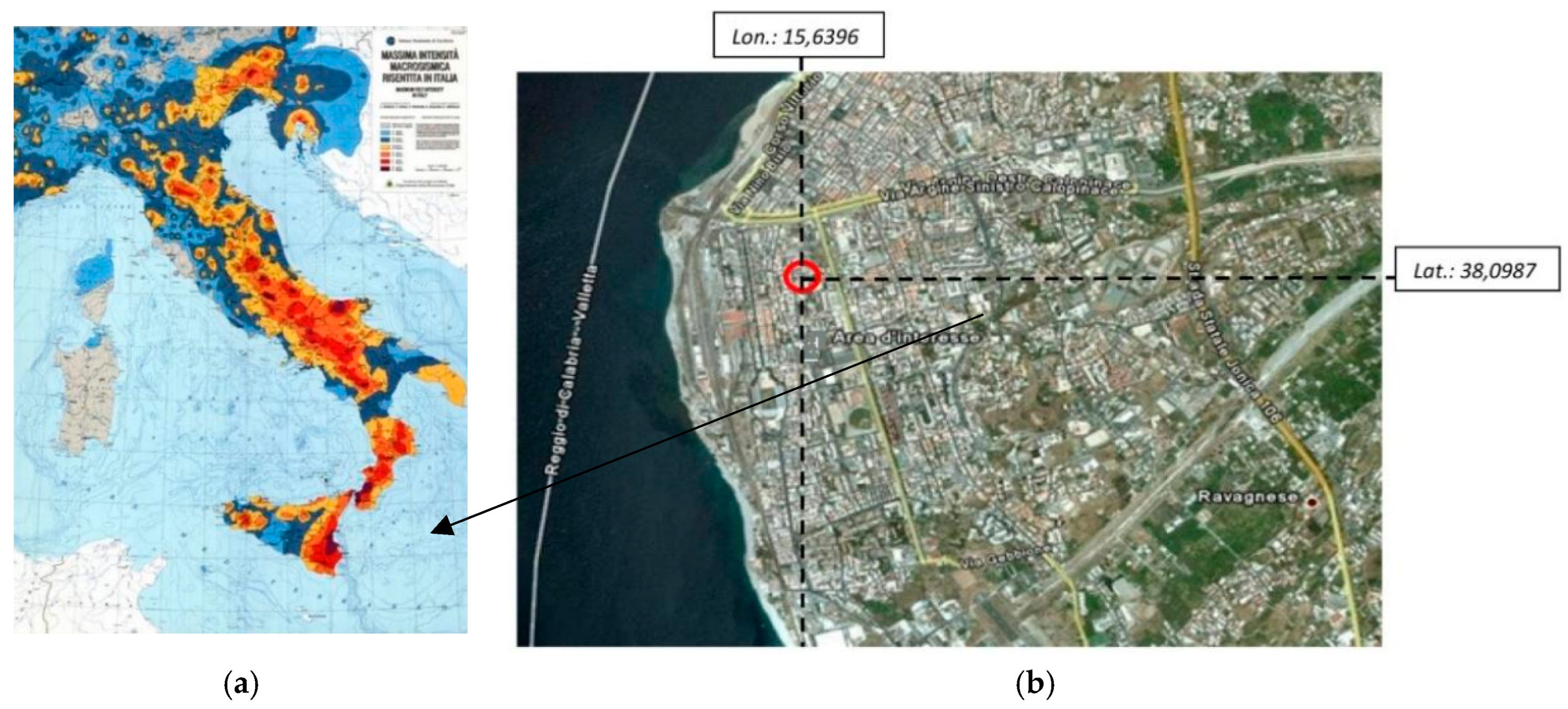
Figure 1. Building context: (a) Italian seismicity and (b) location of the case-study system.
Applsci 12 12894 g001
Figure 2. Summary of (a) seismic intensity and (b) the number of victims of past earthquakes in the Calabria Region.
Applsci 12 12894 g002
Figure 3. Isolation system in use for the present study: (a) cross-sectional schematic view and (b) in-situ installation in the Frangipane School in Reggio Calabria (detail), with (c) experimental response under horizontal and (d) vertical forces.
Applsci 12 12894 g003
Figure 4. Frangipane School in Reggio Calabria: (a) top view and (b) front view (South side), with evidence (red box) of the area of retrofit intervention, and (c) outside view.
Applsci 12 12894 g004
Figure 5. Frangipane School in Reggio Calabria: (a) vertical and (b) horizontal cross-sections (out-of-scale, with dimensions in m).
Applsci 12 12894 g005
Figure 6. Examples of geometric details for (a) columns and (b) beams for the Frangipane School (scanned technical drawings), with dimensions in cm).
Applsci 12 12894 g006
Figure 7. In-field experimental investigation (selected examples): (a) magnetometric inspection for a pillar; (b) foundation system; (c) rebars and stirrups of RC members; (d,e) concrete and steel rebar samples for mechanical characterization of materials.
Applsci 12 12894 g007
Figure 9. Fundamental vibration modes of the MU system (Midas): top view and axonometric view. (a) Mode 1 T1 = 0.5542 s (M = 75.02%). (b) Mode 2 T2 = 0.4648 s (M = 76.82%). (c) Mode 3 T3 = 0.4515 s (M = 76.45%).
Applsci 12 12894 g009
Figure 15. Scales spectra for the site of Reggio Calabria, Mean spectra and code spectra for a soil type B, with evidence of (a) Operational Limit State (OLS), (b) Damage Limit State (DLS), (c) Life-Safety Limit State (LSLS) and (d) Collapse Limit State (CLS).
Applsci 12 12894 g015
Publisher’s Note: MDPI stays neutral with regard to jurisdictional claims in published maps and institutional affiliations.