Abstract
In this study we report the effect of fuel type (biodiesel vs. methane), flame structure and flame height (inner-cone vs. outer-cone), and the percent of oxygen content in the oxidizer stream for the formation of hydrophobic carbon layers using co-flow diffusion flames. It was found that a flame formed using a gaseous fuel (methane) over a vaporized liquid fuel, Canola Methyl Ester (CME), has significant structural differences that enable vastly different deposition behavior of soot layers on the surface of solid substrates. Due to its larger pyrolysis zone (taller inner-cone), the CH4/air flame has a smaller region that supports uniform soot deposition of hydrophobic carbon layers (C-layers) compared to the CME/air flame. When a solid substrate is placed within the pyrolysis zone (inner-cone) of a flame the resulting layer is non-uniform, hydrophilic, and consists of undeveloped soot. However, when outside the pyrolysis zone, the deposited soot tends to be uniform and mature, ultimately creating a hydrophobic C-layer consisting of the typical microscale interconnected weblike structures formed of spherical soot nanoparticles. The effect of oxygen content (35% and 50% O2) in the oxidizer stream for the formation of hydrophobic C-layers was also studied in this work. It was found that oxygen enrichment within the CME flame alters the structure of the flame, hence affecting the morphology of the formed C-layer. Under oxygen enrichment the central region of the deposited C-layer is composed of a weblike structure similar to those seen in the air flames; however, this central region is bordered by a region of densely compacted soot that shows signs of significant thermal stress. At 35% O2 the thermal stress is expressed as multiple microscale cracks while at 50% O2 this border region shows much larger cracks and macroscale layer peeling. The formed C-layers under the different flame conditions were tested for hydrophobicity by measuring the contact angle of a water droplet. The morphology of the C-layers was analyzed using scanning electron microscopy.
1. Introduction
Hydrophobic materials have the unique ability to repel water and are generally characterized by a low surface energy and rough topographical microstructure, nanostructure, or a hierarchical combination of the two. The hydrophobic properties of a material can be determined by the contact angle (CA) made by a water droplet placed on the material. The contact angle is defined as the angle made between the bottom of the droplet and the line tangent to the edge of the droplet at the surface liquid contact point. Materials that produce CAs greater than 90° are considered hydrophobic and materials with CAs exceeding 150° are considered superhydrophobic.
It has been reported that the hydrophobicity of a material is influenced by its surface topography [1,2,3,4]. Typically, hydrophobic materials are characterized by microscale roughness while superhydrophobic materials exhibit hierarchical roughness, where microscale surface structures contain finer nanoscale architectures. Through surface roughening and creating these hierarchical structures researchers have been able to transform a hydrophilic material into a hydrophobic one [2,4]. A significant portion of hydrophobic material research concentrates on the formation of micro and nanoscale roughness on materials.
Hydrophobic surfaces can be further classified into one of two states: the Wenzel state (a wetting state) and the Cassie–Baxter state (a non-wetting state). In the Wenzel state, a wetting state, the water droplet’s surface tension will be broken and wet the surface; this acts to adhere the water droplet in place and the droplet resists moving across the material [5,6,7]. In the Cassie–Baxter state, a non-wetting state, the water droplet’s surface tension is unbroken. The water droplet rests upon the liquid/solid/air interface created by the water droplet, captured air pockets within the micro/nanostructure of the surface, and the surface itself. In the Cassie–Baxter state, the water droplet can freely and easily move across the material; this characteristic is utilized in many applications, such as self-cleaning materials, corrosion prevention, anti-fouling, microfluidic controls, aviation, etc. [8,9,10,11,12,13,14].
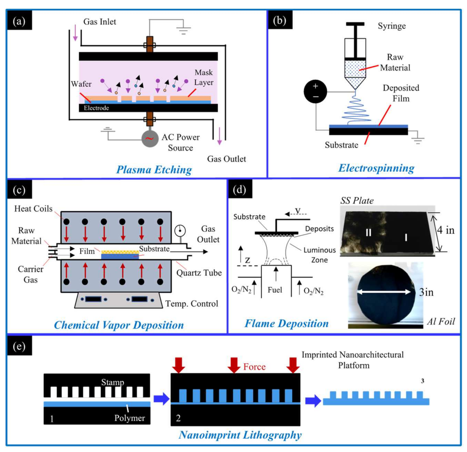
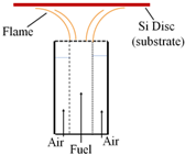
Due to the wide variety of applications for hydrophobic materials there is significant demand. There are many methods for creating hydrophobic surfaces, and all methods change the surface morphology of a material to make it rougher on the microscale, nanoscale, or some combination of the two (a hierarchical roughness). Common methods to create this micro/nanoscale roughness are through (i) plasma etching, which utilizes a low-pressure chamber where energized gas ions pelt a surface to roughen it. The ionic sputtering creates nanoscale imperfections in the surface that ultimately grant the substrate hydrophobic properties (Figure 1a) [15]. (ii) Electrospinning utilizes a DC voltage difference between a spinneret containing a polymer solution/molten polymer and a grounded substrate. The voltage difference allows for the easy collection of the material expelled from the spinneret (Figure 1b). The fine wires/strands expelled have nanoscale features and are ideal for creating a hydrophobic mesh on a substrate [16]. (iii) Chemical vapor deposition (CVD) creates a hydrophobic surface coating via sequential chemical processes (Figure 1c). The substrate is placed in the CVD chamber and a carrier gas transports gas phase precursors into the CVD chamber. Chemical reactions between the precursors and substrate create two products [17], a volatile product that is whisked away by the carrier gas as well as a film/coating on the substrate. (iv) Flame deposition involves placing a substrate within, or above, a flame volume and allowing soot deposits to form a thin continuous layer. Substrates of various material, geometries, and structure can be utilized. As shown in Figure 1d, a soft foil and a rigid plate can be easily coated. The deposited soot creates a rough hierarchical architecture on the substrate that imparts hydrophobic properties [18,19,20,21,22,23,24,25,26,27,28,29,30]. (v) Nanoimprint lithography involves a pre-etched stamp that is used to mold nanoscale features onto a polymer that has been heated (Figure 1e). Once the polymer is heated to its glass transition temperature the stamp is pressed into the polymer, deforming the polymer and creating micro- and nano-architectures [31]. The polymer/stamp are cooled, and once the polymer has solidified the stamp is removed, leaving the substrate and imprinted polymer bonded together. The mentioned methods are effective and have been shown to create hydrophobic and superhydrophobic surfaces; however, the flame method distinguishes itself as being exceedingly simple and rapid, with researchers using fuels as simple as a candle to create hydrophobic surfaces in minutes.
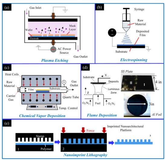
Figure 1.
Schematics of available methods to create hydrophobic surfaces: (a) the plasma etching method; (b) the electrospinning method; (c) the chemical vapor deposition method; (d) the flame deposition method; and (e) the nanoimprint lithography method.
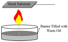
Recently, the flame deposition of hydrophobic carbon deposits onto the surface of substrates has garnered interest by researchers for further development and exploration (Table 1). Researchers have recognized the potential of the flame method’s simple, single step process that is inexpensive, rapid, and readily scalable. The following studies have shown that a variety of different flames and deposition parameters can produce hydrophobic and superhydrophobic surfaces on substrates.

Table 1.
Schematic of various flame techniques used to create hydrophobic carbon layers.
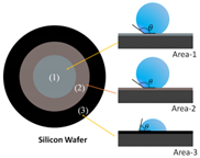
Work by Naha et al. used an ethylene/air co-flow burner to form hydrophobic soot depositions on a silicon substrate [26]. It was found that different deposition areas of the flame produced layers with varying hydrophobic capabilities (Table 1). The morphology of hydrophobic areas was described as “spongy nanobeads” and were located near the center of the substrate. However, depositions at the substrate edge produced hydrophilic globule-like structures. The differences in hydrophobicity were attributed to oxidation of the deposits. Within the fuel cone (central depositions), the small amount of available oxygen promotes soot precursors and the formation of nanobeads that produce hydrophobic layers.
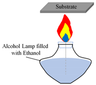
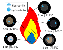
Yang et al. utilized an alcohol lamp filled with ethanol to synthesize hydrophobic materials on glass substrates; additionally, flame temperature was measured at deposition areas [21]. It was determined that hydrophobicity of the deposited soot was dependent on the flame temperature, with flame temperature increasing from 672 °C at the base of the flame to 813 °C near the tip of the flame (Table 1). At a given flame height the temperature decreased from the flame center outwards. At all flame heights tested the outer region of the deposited soot was hydrophilic. At flame heights less than 2 cm the entirety of the deposited soot layer was hydrophilic and at flame heights greater than 2 cm the central area of deposited soot was hydrophobic (Table 1). The pattern of central soot deposits displaying hydrophobic qualities while outer soot deposits were hydrophilic is similar to that observed by Naha. However, unlike Naha, Yang found that both hydrophobic and hydrophilic soot depositions had similar chainlike nano and microstructures when analyzed using SEM. The most significant difference between the hydrophobic and hydrophilic soot deposits was their grain size: a larger grain size of 50 nm for the hydrophobic deposits and a smaller 30 nm grain size for the hydrophilic deposits. The decrease in grain size may have been caused by increased rates of oxidation at the edge of the flame.
Merchan-Breuer et al. compared the hydrophobicity of carbon layers (C-layers) produced in co-flow Canola Methyl Ester (CME) and methane (CH4) air flames at different heights within the flame (Table 1). It was found that formation of the hydrophobic C-layers was highly dependent on flame structure, specifically the pyrolysis zone and the outer luminous zone [20]. Deposition within the pyrolysis zone would not produce hydrophobic soot, while deposition in the luminous zone guaranteed the deposition of hydrophobic soot. It was determined that the CME/air flames, due to being sootier and having a much smaller pyrolysis zone when compared to CH4, are an excellent medium for the creation of hydrophobic C-layers.
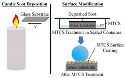
Xiao et al. created hydrophobic soot layers on a glass substrate using a candle and then cleverly modifying the layer with an MTCS coating [30]. The hydrophobicity of the flame-formed soot was not impacted by the MTCS layer, instead its durability was enhanced (Table 1): the MTCS coating improved the durability of the C-layer in high temperatures, corrosive liquids, and scouring via water droplets. Furthermore, upon completion of all durability tests, the deposited soot with the MTCS surface coating remained hydrophobic with only minor decreases in produced water contact angles. This illustrates the capability for flame deposition to be compatible with further enhancement by post-deposition processes.
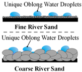
Mansurov et al. was able to create hydrophobic surfaces using waste oil on fine and coarse river sand, showcasing the flexibility of the flame method to work on many different surfaces without using high-quality fuels [27]. When water droplets were placed on the coated river sand, the water was not absorbed, instead the droplets formed unique oblong shapes that followed the curvature of the sand (Table 1).
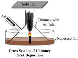
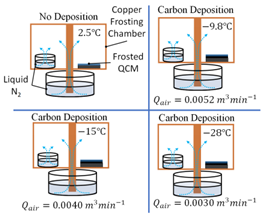
Finally, Esmeryan et al. combusted rapeseed oil with air in a unique chimney burner to produce hydrophobic soot layers for anti-frosting. Air was introduced to the burner at three flow rates: 0.0052 ; 0.0040 ; and 0.0030 . It was found that at each air flow rate, 0.0052 ; 0.0040 ; and 0.0030 , frosting occurred at temperature of , respectively (Table 1). The lowest air flow rate created soot with significantly improved anti-frosting performance that was much more durable than the other layers. Researchers attributed the performance of the soot layers to their surface morphologies. The layer formed at the highest air flow rate consisted of quasispherical aggregates that are known to be brittle, while the more durable layer formed at the lower air flow rate consisted of the more robust modified quasisquare-shaped islands [22].
Some initial flame studies into the formation of hydrophobic C-layers were exploratory in nature and showcased the effectiveness and capability of these flame-formed C-layers. We expanded upon that research, first by testing two fuels, a gaseous fuel (methane) and a vaporized biodiesel fuel made of Canola Methyl Ester, to form hydrophobic carbon films on solid substrates. We also tested the effect of oxygen-enriched air using a CME flame with 35% and 50% O2 to form C-layers and determined the effect that increased oxygen content has on C-layer structure and hydrophobic properties. Data collected include the mass of the C-layer, degree of hydrophobicity of the C-layer (via measuring the CA of a water droplet placed on the C-layer), identifying flame regions that resulted in the formation of a C-layer (recorded as Height Above Burner (HAB)), and the effect of time over which the C-layer was formed (recorded as substrate residence time); these results are discussed in Section 3.
Our findings allowed us to determine that the flame method for creating hydrophobic surfaces is effective and allows for the creation of C-layers with customizable properties based on fuel type, oxygen content, residence time, and deposition location within the flame. The research presented in this paper provides a general guide of how to create hydrophobic C-layers and how to alter properties of the deposited layer by controlling deposition parameters. By utilizing the hierarchical nature of deposited soot, we can create hydrophobic films on stainless steel substrates. These flame-formed hydrophobic C-layers are a promising technology for industrial application to create effective hydrophobic surfaces quickly and at a low cost.
2. Materials and Methods
In this study a flame deposition process was used to form hydrophobic C-layers on stainless steel substrates. The stainless steel (SS) substrates consist of disks that are 19 mm in diameter and resistant to high temperatures. A modified version of the co-flow burner developed by Santoro et al. [32] for studying methane/ethane flames was used to create methane and biodiesel flames. Once the flames were formed, the SS substrate was mounted on an aluminum substrate holder and positioned at specified heights above the burner nozzle (HAB). Once the C-layers were deposited the coated SS substrates were imaged using scanning electron microscopy (SEM). Finally, a water droplet test was used to determine the hydrophobicity of the flame-formed deposits: a water droplet is placed on the coated substrate’s surface and an image is taken of the resting water droplet. Computer software is used to determine the CA. If the measured CA is less than 90 the surface is considered hydrophilic, at CAs greater than 90° the surface is considered hydrophobic, and at CAs greater than 150° the surface is considered superhydrophobic (Figure 2d).
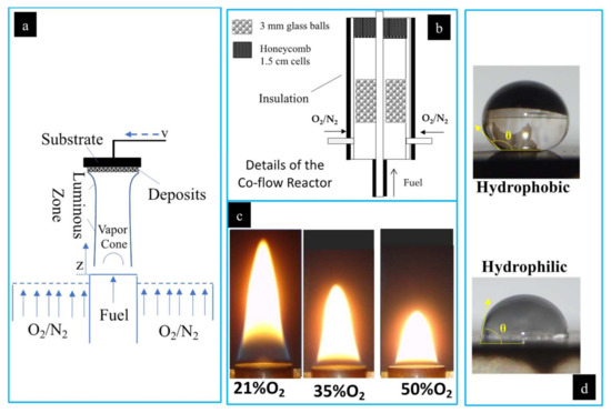
Figure 2.
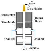
Experimental setup is shown. (a) Two-dimensional representation of the deposition process of soot on an SS substrate from the co-flow flame; (b) detailed co-flow reactor schematic; (c) photograph of the CME/oxygen-enriched air flame at O2 contents of 21%, 35%, and 50%; (d) photographs of water droplets on a hydrophobic and hydrophilic surface with contact angles illustrated.
Flames for this study were produced as shown in Figure 2a,b. Various types of generated flames (two different fuels and varying oxygen content in the oxidizer stream) were tested for forming the carbonaceous deposits on the SS substrate. Fuel (gaseous or vapor) enters the burn zone through a central inlet with the oxidizer flowing through an annular region around the fuel inlet. The oxidizer used consisted of 21% O2 (air), 35% O2, and 50% O2, with N2 as the balance. The oxidizer was funneled through the annulus created by concentric pipes 11 mm and 82 mm in diameter. The central pipe carried the fuel, and the outer pipe supplied the oxidizer via four inlet ducts (Figure 2b). The co-flow burner housed an arrangement of glass balls and a honeycomb lattice within the annulus that acted to stabilize the air flow and ensure a uniform, laminar flow (Figure 2b). The fuel and air were not mixed until they were introduced by diffusion to the flame zone.
Using a syringe pump the liquid CME fuel was introduced at a rate of 6 mL/h to the fuel evaporator line. The evaporator line was heated via heating tapes, and the CME was evaporated. A nitrogen flow was used as a carrier gas (<0.1 Lpm) to move the evaporated CME through the fuel line, allowing for a more stable and easily ignitable flame. Methane, being a gas, did not require a carrier gas; therefore, a methane flow rate of 0.45 Lpm was used. For both fuels the oxidizer utilized a flow rate of 36 Lpm.
To allow for accurate deposition of the flame-formed C-layers the burner was placed on a 2-D positioning system controlled by an 8300 series stepping motor controller (Model VXM-2, Velmex, Inc., Bloomfield, NJ, USA). The burner could be moved horizontally and vertically for optimal flame positioning [33]. By repositioning the burner, it was possible to form C-layers at a range of different heights within the flame.
A hood and series of ducts were used to direct exhaust gases away from the setup. Figure 2a depicts the deposition process that allowed for formation of hydrophobic carbon films on the substrate. The soot deposition process created a black layer of material on the surface of the substrate. After deposition, the formed C-layers/flame deposits were analyzed using a light microscope and scanning electron microscope (SEM). High-magnification SEM image analysis was utilized in order to document the impact flame conditions had on the morphology of the carbonaceous films. Once SEM analysis was completed the flame-treated substrates were classified as hydrophobic, superhydrophobic, or hydrophilic via CA analysis. As shown in Figure 2d the CA was measured by placing a water droplet on the surface of the substrate, capturing a photograph of the water droplet resting on the surface, and using digital micrograph software to measure the CA of the water droplet. Note that the contact angle, θ, is measured between the line parallel to the surface of the substrate at the base of the water droplet and the line tangent to the water droplet (Figure 2d).
C-layers were formed on SS substrates using three different flames (Flame I, II, and III), as shown in Table 2. Changes in surface morphology/structure, degree of hydrophobicity, and mass of the flame deposits were observed based on the following: (a) substrate insertion height into the flame; (b) fuel types used in the burner (CME vs. CH4); and (c) amount of oxygen in the oxidizer stream (21%, 35%, and 50%). Initially, the effect of flame height on the C-layer formed was explored by inserting the substrate into the CME/air flame at four different heights (10, 12, 15 and 20 mm) for a resident time of 5 min (Table 2—Flame I); the total length of the CME/air flame was approximately 22 mm. Next, the effect of fuel type was investigated by using a methane/air flame (Table 2—Flame II). The substrate was inserted into the CH4/air flame for a residence time of 1 min at 50 and 60 mm HAB; the total height of CH4/air flame was approximately 85 mm. The final flame, Flame III, utilized CME as the fuel and the oxygen content within the oxidizer stream was increased from 21% (air) to 35% and then 50% O2 (N2 made up the balance of the oxidizer). The SS disk was inserted into the flame volume at approximately three-quarters the flame height for a residence time of 5 min for all oxygen contents. At 21% O2 the flame was ~21 mm in height and the substrate was inserted at ~15 mm HAB; at 35% O2 the flame was ~12 mm in height and the substrate was inserted at ~9 mm HAB; and at 50% O2 the flame was ~10.6 mm in height and the substrate was inserted at ~8mm HAB. All tested flame parameters are shown in Table 2. A shortened residence time was utilized for the methane–air flame due to increased flame temperatures, to limit thermal strain to the substrate holder and to avoid rapid oxidation of deposited soot. The CME–air flame ranged from ~490 near the burner inlet (HAB = 1.4 mm) to ~870 at the tip of the flame (20 mm), while the methane–air flame temperature ranged from ~740 near the burner inlet (HAB = 9.8 mm) to ~1200 at the tip of the flame (HAB = 80 mm).
Table 2.
Summary of flame parameters for C-layer formation.
3. Results
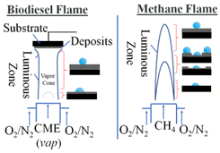
Both the CME/air and CH4/air flames are comprised of two flame regions: the upper and lower region. The upper region of the flames consists of the yellow luminous zone; this flame region is abundant in soot particles, and the yellow hue of the flame occurs due to the radiative heat transfer from the present soot. The lower flame region consists of a clear pyrolysis zone which is typically devoid of soot, hence a “clear” appearance. While both flames contain these two regions, the structure of the flame varies significantly. The CH4/air flame has a much longer pyrolysis zone (also referred to as the “inner-cone”) than the CME/air flame, leading to a unique annular soot deposition pattern. The difference in flame structure is attributed to the difference in CME and methane. Chemically, methane (CH4) is a much more simple fuel than the complex mixture of monoalkyl ester of long-chain fatty acids that make up biodiesels [34,35]. In prior studies the biodiesel flame was found to be much sootier, displaying a larger luminous zone than the methane flame [35,36]. Additionally, the oxygen-enhanced combustion of CME produced a unique flame structure; in contrast to the CME/air and CH4/air flames, the CME/oxygen-enhanced (35% O2 and 50% O2) flames produced a barely discernable pyrolysis zone that was only visible at the burner inlet/base of the flame (Figure 2c). Alteration of the flame structure allows for the modification of deposited soot, ultimately affecting the properties (mass, hydrophobicity, stability, etc.) of the deposited C-layer. Leveraging this improved control of the flame deposits’ properties may allow for the creation of highly customizable C-layers that meet specific requirements of mass, thickness, hydrophobicity, and stability without requiring post-deposition processes.
3.1. Carbon Deposits Formed in CME/Air and CH4/Air Flames
3.1.1. CME/Air Flame
In Flame I, the CME/air co-flow flame, the substrate was inserted into the flame volume for a residence time of 5 min at an HAB of 10 mm, 12 mm, 15 mm, and 20 mm. By varying the HAB, carbonaceous deposits display a change in total mass, uniformity, thickness, degree of hydrophobicity, and surface morphology (Figure 3A). Increasing substrate insertion height was followed by changes in uniformity, with the deposits evolving from individual clusters at the very base of the flame (Figure 3A(a1,a2)) to interconnected weblike structures midway in the flame (Figure 3A(b1,b2,c1,c2)), and finally forming a highly uniform layer with few voids at the tip of the flame (Figure 3A(d1,d2)). The changes in C-layer uniformity were generally accompanied by an increase in degree of hydrophobicity (measured by CA), with the only decrease in CA being 1 as the substrate insertion HAB increased from 15 mm to 20 mm.
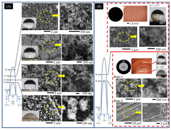
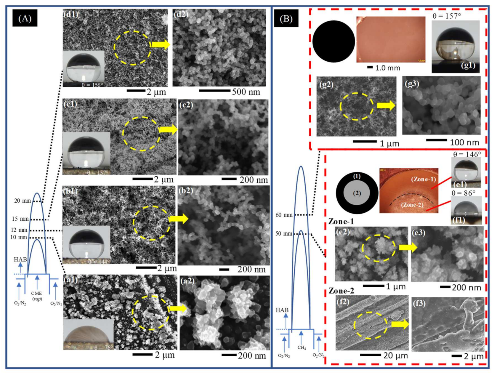
Figure 3.
Representative SEM images of early soot deposits to fully developed hydrophobic films deposited on the surface of the SS substrate introduced at various HAB for a (A) CME/air and (B) CH4/air flames. (A) Deposits formed in Flame I at HAB of 10 mm (a1,a2), 12 mm (b1,b2), 15 mm (c1,c2), and 20 mm (d1,d2) for a substrate residence time of 5 min. (B) Deposits formed in Flame II at HAB of 50 mm (Zone-1 (e1–e3) and Zone-2 (f1–f3)) and 60 mm (g1–g3) for a substrate residence time of 1 min.
At a substrate insertion height of 10 mm HAB the deposits formed are barely discernable to the naked eye, displayed hydrophilic characteristics, and formed a unique “granular-like” microstructure (Figure 3A(a1,a2)). This insertion height of the substrate coincides with the boundary between the pyrolysis zone and the luminous zone of the flame: there is hardly any soot present at this point, and if soot were present, it would be located towards the outer radius of the flame [34,35,37]. At 12 mm HAB a thin layer of soot is deposited on the substrate, measuring only 1 mg in mass, and displaying hydrophobic (CA properties. At this point, the first instance of “spiderweb-like” soot structures were deposited from the CME/air flame (Figure 3A(b1,b2)). Increasing substrate insertion height to 15 mm HAB produced a noticeably thicker C-layer with a significant increase in mass to 5 mg (Figure 3A(c1,c2)). At this HAB the first superhydrophobic C-layer is formed from the CME/air flame (CA ). Additionally, the weblike structures appear much more defined than those formed at 12 mm. At the final substrate insertion height into the CME/air flame at 20 mm HAB the mass of the deposited carbon film peaked (9 mg) and the layer remained superhydrophobic (CA ). These deposition characteristics show a correlation between C-layer properties (mass, thickness, hydrophobicity, and surface morphology) and the substrate’s insertion point into the flame height.
The hydrophobicity of the deposited carbon film depends on the film’s unique surface morphology. The non-uniform and “granular-like” deposits formed at 10 mm HAB are unable to support and maintain the water droplet’s shape. Therefore, the surface of the water droplet breaks and the water spreads across the substrate, indicating that the surface is hydrophilic. When HAB was increased to 12 mm the C-layer began to display a “spiderweb-like” structure. This type of branching structure was also present at an HAB of 15 mm; however, the branches appear to be more densely packed together and better defined than those at 12 mm. This webbed structure creates a surface full of nanoscale air pockets that allow the water droplet to rest on the surface without wetting the substrate. The behavior of the water droplet resting on the surface and not breaking its surface tension conforms to the Cassie–Baxter state of hydrophobicity.
3.1.2. CH4/Air Flame
In Flame II, a CH4/air co-flow flame, the substrate was inserted into the flame volume at an HAB of 50 mm and 60 mm for a residence time of 1 min. The shortened residence time of the substrate in this flame ensured that deposited carbonaceous material was not oxidized during the deposition process and avoided excess thermal stress on the substrate holder.
The introduction of the disc at 50 mm HAB resulted in deposition of the carbonaceous material, forming two distinct regions on the surface of the substrate. The deposits resemble the shape of a flat washer with an inner and outer diameter. The center area (circular region) has a light contrast resembling the metallic color of the substrate and is encompassed by an outer deposition region of black soot that forms a “ring-like” fixture (Figure 3B (Zone-1, Zone-2)). As illustrated in Figure 3B, the sooty “ring-like” fixture (Zone-1) and the disc center (Zone-2) correspond to different radial areas within the flame. Deposition of Zone-1 material occurred within the luminous envelope at the flame’s outer region while the deposits of Zone-2 originated from the pyrolysis zone in the center of the flame. Zone-2 deposits, similar to the CME/air flame at an HAB of 10 mm, were formed within the pyrolysis zone of the flame where there is little to no soot formation [36], therefore the relatively “clean” center surface shown in light and SEM imaging is to be expected (Figure 3B(Zone-2,f2,f3)). The Zone-1 “ring-like” deposits formed in the luminous zone of the flame produced a hydrophobic C-layer (Figure 3B(e1)). Unlike the hydrophobic layers formed in the CME/air flame, the morphology of Zone-1 deposits is neither interconnected nor weblike. Instead, clusters of non-spherical soot form irregular structures (Figure 3B(e2,e3)) similar in appearance to the quasisquare-shaped islands identified by Esmerayan et al. [19,22].
At a substrate insertion of 60 mm HAB, a superhydrophobic C-layer was formed (Figure 3B(g1–g3)). Unlike the deposits of the “ring-like” pattern formed at 50 mm HAB, the ones formed at 60 mm HAB displayed “spiderweb-like” structures similar to those formed in the middle region of the CME/air flame. This is a notable phenomenon that demonstrates the importance of flame structure for C-layer development: it is possible to create similar C-layers with nearly identical hydrophobic performance from two different fuels by utilizing the structure of the flame and the soot evolution process.
3.2. C-Layers Formed in CME/Oxygen-Enriched Air Flames
The role of oxygen in the formation of soot has been studied by numerous authors [36,38,39,40,41,42], and it has been found that introducing oxygen into a flame increases the rate of soot inception, formation, agglomeration, and oxidation. These fundamental effects on the flame-formed soot may have a profound impact on the structure and hydrophobicity of the flame-formed C-layers. In Flame III the effects of oxygen-enhanced combustion on deposited carbon films were studied using a CME/oxygen-enriched air flame. The SS substrate was inserted into the flame volume at three-quarters the flame height. This relevant insertion height was used due to the overall height of the flame shrinking as oxygen content in the oxidizer stream increased (Figure 2c). Oxygen contents of 21%, 35%, and 50% O2 were used, with respective substrate insertion heights of 15 mm, 9 mm, and 8 mm (Table 2).
At all three O2 contents the substrate was introduced to the flame’s luminous zone and the produced C-layers were hydrophobic (Figure 4(a1–c1)). At 35% O2 the C-layer produced was superhydrophobic (CA = 154) with a mass of 6 mg, a 1 mg increase compared to the air flame. This mass increase coincides with the increase in soot volume fraction between CME combustion with air and 35% O2 [35], indicating a greater abundance of soot in the flame. Furthermore, at 35% O2 the deposited material consists of similar weblike structures that were seen in the CME/air and CH4/air flames (Figure 4(a1–a3,b1–b3)). Once the oxygen content was increased to 50% O2, the flame deposits were no longer superhydrophobic, producing a hydrophobic CA of 146. The decrease in the performance of the layers as a hydrophobic material was accompanied with a drop in mass to a low of 1 mg (compared to 5 mg at 21% O2 and 6 mg at 35% O2). This correlates well with our previous work on soot formation, where it was reported that the soot peak volume fraction of a CME/50% O2 flame was significantly larger than the CME/21% O2 flame; however, when mass of the total soot was measured the mass in the 21% O2 flame was larger than the 50% O2 flame, indicating that soot is undergoing an oxidation process [35].
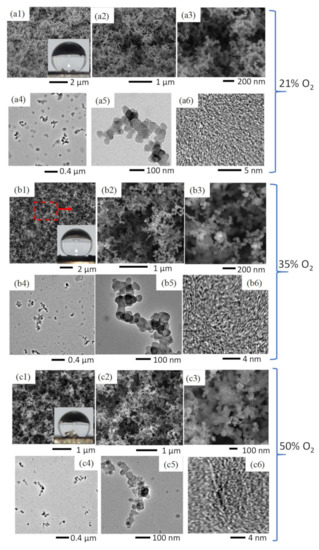
Figure 4.
Comparative SEM images of C-layers formed in a CME/air flame (a1–a3), CME/35% O2 flame (b1–b3), and CME/50% O2 flame (c1–c3). TEM images of soot collected at the respective flame insertion heights of the substrate for the CME/air flame (a4–a6), CME/35% O2 flame (b4–b6), and CME/50% O2 flame (c4–c6).
Oxidation of deposited soot accounts for the reduction in mass as well as the difference in soot development/structure seen in the TEM images (Figure 4(a5–c5)). The soot formed in the CME/air and CME/35% O2 appears to be “irregular-shaped” [34], indicated by a lack of distinct shapes or boundaries of the soot, providing evidence that the soot has not yet been fully carbonized (Figure 4(a4,b4)). It is evident from the TEM images that there is a gradual decrease in the amount of “irregular-shaped” structures, as oxygen is increased from 21% to 35% and finally to 50%.
It is important to note that at all three oxygen contents the hydrophobic portions of the flame-formed C-layers share similar branched, weblike, porous structures (Figure 4(a1–a3,b1–b3,c1–c3)). This not only demonstrates the flame method’s capability to consistently form hydrophobic soot depositions under vastly different conditions, but also emphasizes the importance of these branching hierarchical structures. The hydrophobicity of the current deposited carbon films is due to their surface structure; this is a physical characteristic, not a chemical one. Therefore, the unique topography created via soot deposition is the mechanism that facilitates the hydrophobicity exhibited by the deposited C-films.
The introduction of increased oxygen in the oxidizer stream prompted the formation of surface cracks on the C-layer (35% and 50% O2; Figure 5(b2,d2)) as well as layer peeling (50% O2; Figure 5(c1)). These surface instabilities were attributed to the increase in temperature that accompanies increased oxygen content in the oxidizer stream during combustion. The CME/air flame at an HAB of 15 mm produced a flame temperature of 788 . Flame temperature increased to a peak of 938 at an HAB of 8 mm when oxygen content increased to 50% O2. Furthermore, these instabilities occurred at the edge of the C-layer, which corresponds to the edge of the flame (location of flame/oxidizer interaction) where the flame temperature would be highest [43].
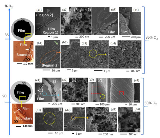
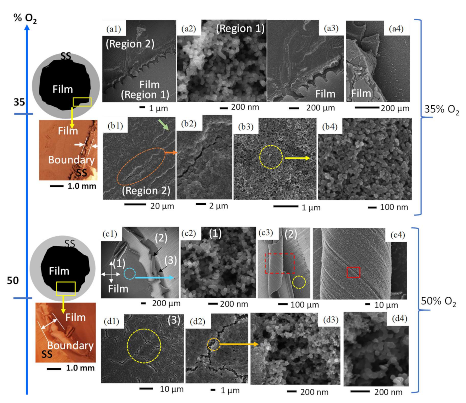
Figure 5.
Comparative diagrams, light microscopy images, and SEM images of C-layers formed in CME/35% O2 and CME/50% O2 flames. At 35% O2, a light and dark contrast was observed (a1–a4), with the lighter-contrast area producing weblike structures (a2) and the area of darker contrast consisting of compacted soot with microscale cracks (b1–b4). CME flames with 50% O2 produced three regions of deposits (c1). the first formed by typical weblike structures (c2); the second made up of early soot deposits that have been curled (c3,c4); and the third comprising compacted soot that has been significantly fractured (d1–d4).
The introduction of an intermediate amount of oxygen in the oxidizer stream (35% O2) resulted in black sooty film deposits with visible evidence of structural instability and non-uniformity. This is evidenced by distinct deposition zones: (Region 1) an area of weblike structures bordered by (Region 2) a region of compacted soot (Figure 5(a1,a2,b1–b3)). These varying deposition areas/zones are created by significant temperature gradients within the flame as well as the thermal stress experienced by the cold substrate interacting with the hot CME/oxygen-enriched air flame.
The deposited film formed at 35% O2 shows significant modification of its surface morphology compared to the air-counterpart. The deposited carbonaceous film exhibits two different contrasts under the electron beam (Figure 5(a1)), a larger inner circular deposition of a “light-contrast” enclosed by a thin outer “darker-contrast” area (Region 1 and Region 2 in Figure 5(a1)). HR-SEM imaging of Region 1 reveals that this part of the deposited film is composed of the typical structure of mature soot: deposits are formed of shorter, chain-like structures made up of tens of nearly-spherical carbon beads and branched aggregates (Figure 5(a2)); this type of morphology is very similar to that found in the CME/air flames. However, the entirety of the deposited C-layer does not share this morphology. Region 1 and Region 2 are clearly separated by a boundary (Figure 5(a1,a3,a4)); higher resolution SEM imaging shows large morphological variations between soot deposits of Region 1 and Region 2.
The carbonaceous deposits on the “darker-contrast” portion of the layer (Region 2) do not display the typical weblike structures, instead it appears as if the particles are joined together, and the agglomerates have been compacted to fill the voids (Figure 5(b3,b4)). Further SEM imaging of Region 2 reveals unique structural cracking (Figure 5(b1,b2)). These cracks are initial signs of thermal stress/fatigue, and while very small (widths < 1 μm) they can be seen at multiple locations across Region 2. Such unique defects are neither observed in Region 1 nor the CME/air flame. We hypothesize that these effects are due to thermal stresses caused by the increase in flame temperature inherent to oxygen-enriched combustion. Furthermore, flame temperature increases from the center of the flame to its outer radius, providing an explanation as to why these cracks are only found on the perimeter of the C-layer. As the SS substrate is exposed to the hot flame medium it expands and once removed from the hot flame, with the attached deposits, it cools and contracts; this rapid sequence of expanding and contracting forms small cracks on the deposited C-layer.
The film formed on the substrate by the CME/50% O2 flame shows a wide variety of macro and nanoscale morphologies, including the weblike interconnected structures that are typical of hydrophobic flame-formed carbon deposits; surface cracks and fractures that were first seen in the CME/35% O2 deposition layer; and unique curled portions of the C-layer that have not been observed before. These unique morphologies are brought out by the intense temperature conditions of the CME/50% O2 flame.
As seen in Figure 5c1, there are three distinct morphological regions of the CME/50% O2 flame-formed film: (1) the hydrophobic inner region; (2) the region of curled soot layers; and (3) the uncurled perimeter of the deposited film. Region 1 consists of interconnected carbon spherules that form a weblike structure similar to the morphologies common in the CME/air flame (Figure 5c2). Region 2 consists of peeling carbon layers that were easily observed even by the naked eye (Figure 5(c1,c3,c4)). Curled portions of the deposit have easily visible engraved lines (Figure 5(c2,c3)) that correlate to the grooves present on the surface of the SS disk (Figure 5(c3)), indicating that the soot exposed by the curls are early deposits. HR-SEM analysis of these early deposits show interconnected carbon branches similar to those found in Region 1. Region 3 of the film is located at the perimeter of the deposition zone (Figure 5(c1)) and can most easily be characterized by the large cracks on its surface (Figure 5(d1,d2)). These cracks are significantly larger in size than those found at 35% O2 and appear in much greater quantity. However, looking within the cracks of the CME/50% O2 layer using HR-SEM provides great insight into the morphology of early soot deposits. It appears that earlier deposited soot consists of weblike structures comparable to structures found in Region 1 (Figure 5(d3,d4)); this is consistent with HR-SEM imaging of the curled layers in Region 2. Additionally, the surface of Region 3 consists of compacted soot spherules that have not formed interconnected weblike structures and are similar to the deposits in the darker-contrast area of the film formed at 35% O2 (Figure 5(b3,b4,d2,d3)). We believe that these unique morphologies were created by the high temperatures of the CME/50% O2 flame, specifically at the high-temperature area at the edge of the flame where Regions 2 and 3 were located.
Both flames formed in CME/oxygen-enriched combustion (35% O2 and 50% O2) could produce hydrophobic layers; however, there were signs of instability that were not observed in other flame-formed layers. These instabilities occurred at the perimeter of the formed C-layer, where during deposition the flame temperature would be greatest. Both CME/35% O2 and CME/50% O2 flame-formed layers showed signs of thermal stress-induced cracking. Additionally, the CME/50% O2 layer had areas where the once planar soot began to curl, which provided evidence that early soot deposits consisted of the typical weblike structures. Interestingly, both levels of oxygen enhancement showed similar morphologies of compacted soot spherules near areas of high thermal stress (Figure 5(b3,d3)). This provides evidence that the high-temperature areas of the flame are modifying what was once a weblike structure into a compacted bed of nanosoot beads.
4. Discussion
This research explored the use of various flame parameters to create hydrophobic and superhydrophobic C-layers through a flame deposition process. This flame method is an inexpensive and rapid single step process that consistently creates a hydrophobic layer on an SS substrate while providing operators a significant amount of control over the deposited layer. The physical characteristics of the C-layer formed (degree of hydrophobicity, mass, thickness, and stability) can be controlled by fuel type of the flame, residence time of the substrate within the flame, insertion height of the substrate into the flame, and the amount of oxygen used during combustion.
By adjusting the height at which the substrate is inserted into the CME/air flame volume, the mass, thickness, hydrophobicity, and surface structure of the C-layer was adjusted. To form a C-layer the substrate needed to be inserted into the flame above the pyrolysis zone, as within the pyrolysis zone a negligible amount of “granular-like” soot is deposited which does not promote hydrophobicity (Figure 3(a1,a2)). However, above the pyrolysis zone, specifically in the yellow luminous zone, hydrophobic films are readily formed. As substrate insertion height into the flame volume increased, the mass and thickness of the flame deposits also increased. Furthermore, the degree of hydrophobicity of the C-layer generally increased as well; C-layers at the lower region of the flame produced lower CAs compared to those formed in the upper region of the flame. This can partly be attributed to the change in structure of soot deposits between these two deposition regions. At the lower region (12 mm HAB), deposits appear to be much less densely packed and defined (Figure 3(b1,b2)) compared to the upper regions (≥15 mm HAB) of the flame (Figure 3(c1,c2,d1,d2)).
By changing the fuel type used in the flame (CME vs. CH4) it was possible to produce significant changes in the structure of deposited soot. At 50 mm HAB, the hydrophobic annular deposit has a unique microstructure unlike any formed within the CME flames. These were the only non-spherical soot deposits that displayed hydrophobic properties (Figure 3(e2,e3)). By adjusting insertion height of the substrate within the CH4 flame, the structure of deposition was further altered. At an insertion height of 60 mm HAB a uniform hydrophobic C-layer was formed that shared similar structures to the CME/air flame. However, the particulates making up these weblike structures were finer than those of the CME/air flame (Figure 3(g2,g3)). The significant difference in structure of the soot deposits between insertion heights of 50 and 60 mm have large impacts on the hydrophobicity of the formed C-layers; the unique structures formed at the lower region of the flame were hydrophobic while the typical weblike structures formed in the upper region were superhydrophobic. It is important to recognize that by using a CH4/air flame it was possible to create hydrophobic C-layers with both similar (60 mm HAB) and drastically different (50 mm HAB) microstructures to those formed in the CME/air flame, demonstrating the importance of flame structure for hydrophobic soot deposition.
Finally, by adjusting the amount of oxygen used in the CME flame there were dramatic changes in the flame structure, most significantly a reduction in flame size, which also impacts the rate of soot formation and growth. Under these conditions there were significant changes to deposited C-layer mass, degree of hydrophobicity, stability, and surface structure. Increasing the O2 content from 21% O2 to 35% O2 showed changes in surface stability and morphology of the deposited film. At 35% O2 the first instances of thermal stress and cracking were observed as well as highly compacted spherical soot deposits. The fracturing and compacting of deposited soot occurred on the perimeter of the deposition area, which correlates to the increased temperature region of the CME/35% O2 flame. When increasing the oxygen content in the oxidizer stream to 50% there was a decrease in C-layer mass, stability, and hydrophobicity of the deposited film. The mass dropped to a low of 1 mg and the C-layer’s hydrophobicity deteriorated from superhydrophobic to hydrophobic. The stability of the film was severely impacted as this deposition marked the first occurrence of instabilities that could be viewed macroscopically: C-layers were curled at the perimeter of the deposition zone (Figure 5(c2)). Using SEM imaging it was determined that the C-layer was cracking and that these cracks were significantly larger than those found in the CME/35% O2 flame. The instability and cracking of the C-layer at 35% O2 and 50% O2 is attributed to the thermal stresses caused by heightened flame temperatures of oxygen-enriched combustion.
5. Conclusions
In this contribution we showed the capabilities of the flame deposition method to synthesize hydrophobic C-layers. Stainless steel substrates (D = 19 mm disks) were used for the formation of C-layers in a co-flow diffusion flame. It was found that the hydrophobicity and physical properties of the flame-formed C-layers vary as function of parameters, including: (1) flame position (inner-cone vs. outer-cone); (2) fuel type (gaseous vs. vapor); and (3) percent of oxygen content in the oxidizer stream. The introduction of solid substrates within the CH4/air flame’s inner-cone resulted in two very distinct deposition zones. Zone-1 is an outer ring of darker contrast surrounding a circular layer of light contrast (Zone-2). The variation of the contrast is the result of the deposition rate or the presence of the condensed-phase material occurring within the outer flame region. The hydrophobicity of deposited material from the inner-cone of the flame varies with radius along the disk. However, C-layers formed in the outer-cone, regardless of the fuel type, are uniform and hydrophobic. The flame structure (inner-cone vs. outer-cone) varied by the type of fuel and concentration of oxygen used to form a flame. The increase of oxygen in the oxidizer stream resulted in compressed flames (height and diameter). The C-layers formed in the oxygen-enhanced flames exhibit unique structural defects including a smaller region of deposition, peeling of deposits, and cracking at the edges of the films. The C-layers formed in oxygen-enriched air flames are hydrophobic at tested levels of oxygen enrichment (35% and 50% O2).
Impacts of this research show that by varying the fuel type, oxygen content in the oxidizer stream, substrate insertion height, and substrate residence time in the flame hydrophobic films can be formed with desired mass, thickness, surface structure, and stability. Specifically, by altering the structure of the deposited soot it is possible to control the hydrophobicity and stability of the formed C-layer.
Further research of these flame-formed hydrophobic C-layers should explore their durability; all hydrophobic coatings lose their effectiveness due to wear and the eventual destruction of the microstructures on the coating’s surface. The durability of the C-layer as well as potential methods to improve C-layer durability may play a significant role in determining the commercial viability and adoption of the flame deposition method for synthesizing hydrophobic surfaces. The robustness of a hydrophobic surface is typically characterized by its mechanical strength, corrosion resistance, thermal resistance, and (if the layer is deposited on a material) the strength of the material’s adhesion [30,44,45].
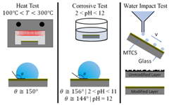
Research groups Xiao et al. and Liu et al. have quantified mechanical strength of hydrophobic surfaces via a water impact test. In this test, water droplets impact the hydrophobic surface (angled at 45) from a set height [30,45]. After a set amount of water volume has impacted the surface, the surface is analyzed for damage. The surface analysis typically consists of SEM imaging (to compare the damage to an untested sample) and measuring new water contact angles. As the hydrophobic surface experiences more damage the degree of hydrophobicity typically decreases and the water droplet CA decreases.
Corrosion resistance of hydrophobic materials has been studied by Xiao et al., Varughese et al., and Liu et al. by immersing the material into an acidic (pH < 7), basic (pH > 7), and neutral (pH = 7) solution for a set time period [30,44,45]. Once the immersion is complete, the hydrophobic material is removed, and SEM imaging/analysis is conducted. The SEM imaging typically reveals how the surface structure was impacted by the acidic, basic, and neutral solutions. CA analysis is also conducted to quantify any reductions in hydrophobicity.
The ability of a hydrophobic material to resist high temperature has been studied by Xiao et al. and Liu et al. They defined thermal resistance of their hydrophobic materials as the structure’s ability to remain hydrophobic after exposure to high temperatures [30,45]. Their materials were heated to temperatures exceeding 200 for a set period. Once the surfaces had been heated and cooled researchers conducted SEM imaging and CA analysis to determine the extent of damage to their samples.
Finally, if the hydrophobic layer consists of deposits on a substrate the adhesion of said deposits to the substrate is tested via immersing the material (substrate and deposits) in a liquid (usually ethanol or water); in some instances, this immersion is accompanied by sonication [30,45]. Once the material has been removed from the liquid, the SEM analysis is conducted to determine surface damage, and CA analysis is completed.
Characterizing the durability of our flame-formed hydrophobic C-layers is a natural progression of our research. In the future we aim to determine how robust our layers are as well as working towards increasing their durability.
Author Contributions
Conceptualization, D.A.M.-B., E.M., B.B., and W.M.-M.; methodology, D.A.M.-B., E.M., B.B., and W.M.-M.; software, E.M.; validation, D.A.M.-B., E.M., B.B., L.C.M.N., and W.M.-M.; formal analysis, D.A.M.-B., E.M., and W.M.-M.; investigation, D.A.M.-B., E.M., B.B., L.C.M.N., Y.L., and W.M.-M.; resources, W.M.-M.; data curation, D.A.M.-B. and W.M.-M.; writing—original draft preparation, D.A.M.-B., L.C.M.N., Y.L., and W.M.-M.; writing—review and editing, D.A.M.-B., E.M., B.B., L.C.M.N., Y.L., and W.M.-M.; visualization, Y.L. and W.M.-M.; supervision, Y.L. and W.M.-M.; project administration, W.M.-M.; funding acquisition, W.M.-M. All authors have read and agreed to the published version of the manuscript.
Funding
This work is an extension of the research on the analysis of carbon particulates produced in combustion of biodiesels supported by the National Science Foundation through the grants CBET-1067395 and REU CBET-1440030 which are gratefully acknowledged. This research was also partially founded by the Office of the Vice President for Research at the University of Oklahoma.
Institutional Review Board Statement
Not applicable.
Informed Consent Statement
Not applicable.
Data Availability Statement
Data is contained within the article.
Acknowledgments
Many thanks to Preston Larson and Andrew Madden, experts in microscopy imaging from the Samuel Roberts Noble Electron Microscopy Laboratory located at the University of Oklahoma. Their support and expertise helped us capture many of the images that are shown in this publication. Additionally, we would like to provide many thanks to Alan Nicholls from the Electron Microscopy Service (EMS) at the University of Illinois at the Chicago Research Resource Center (UIC-RRC). His expertise in TEM imaging and analysis allowed for the thorough capture and analysis of TEM images. The Oklahoma Luis Stokes Alliance for Minority Participation (OK-LSAMP) must also be thanked. As an OK-LSAMP Scholar DAMB had the unique opportunity and mentorship to partake in this research project.
Conflicts of Interest
The authors declare no conflict of interest.
References
- Whyman, G.; Bormashenko, E. How to make the Cassie wetting state stable? Langmuir 2011, 27, 8171–8176. [Google Scholar] [CrossRef] [PubMed]
- Bormashenko, E.; Bormashenko, Y.; Whyman, G.; Pogreb, R.; Stanevsky, O. Micrometrically scaled textured metallic hydrophobic interfaces validate the Cassie-Baxter wetting hypothesis. J. Colloid Interface Sci. 2006, 302, 308–311. [Google Scholar] [CrossRef] [PubMed]
- Gao, L.; McCarthy, T.J. The “lotus effect” explained: Two reasons why two length scales of topography are important. Langmuir 2006, 22, 2966–2967. [Google Scholar] [CrossRef] [PubMed]
- Wang, D.; Sun, Q.; Hokkanen, M.J.; Zhang, C.; Lin, F.Y.; Liu, Q.; Zhu, S.-P.; Zhou, T.; Chang, Q.; He, B.; et al. Design of robust superhydrophobic surfaces. Nature 2020, 582, 55–59. [Google Scholar] [CrossRef]
- Wenzel, R.N. Resistance of solid surfaces to wetting by water. Ind. Eng. Chem. 1936, 28, 988–994. [Google Scholar] [CrossRef]
- Cassie, A.B.D.; Baxter, S. Wettability of porous surfaces. Trans. Faraday Soc. 1944, 40, 546–551. [Google Scholar] [CrossRef]
- Patankar, N.A. Mimicking the lotus effect: Influence of double roughness structures and slender pillars. Langmuir 2004, 20, 8209–8213. [Google Scholar] [CrossRef]
- Yin, Q.; Guo, Q.; Wang, Z.; Chen, Y.; Duan, H.; Cheng, P. 3D-printed bioinspired Cassie-Baxter wettability for controllable microdroplet manipulation. ACS Appl. Mater. Interfaces 2021, 13, 1979–1987. [Google Scholar] [CrossRef]
- Chermahini, S.H.; Ostad-Ali-Askari, K.; Eslamian, S.; Singh, V.P. Recent progress in self-cleaning materials with different suitable applications. Am. J. Eng. Appl. Sci. 2018, 11, 560–573. [Google Scholar] [CrossRef]
- Faustini, M.; Nicole, L.; Boissière, C.; Innocenzi, P.; Sanchez, C.; Grosso, D. Hydrophobic, antireflective, self-cleaning, and antifogging sol-gel coatings: An example of multifunctional nanostructured materials for photovoltaic cells. Chem. Mater. 2010, 22, 4406–4413. [Google Scholar] [CrossRef]
- Chang, K.-C.; Hsu, M.-H.; Lu, H.-I.; Lai, M.-C.; Liu, P.-J.; Hsu, C.-H.; Ji, W.-F.; Chuang, T.-L.; Wei, Y.; Yeh, J.-M.; et al. Room-temperature cured hydrophobic epoxy/graphene composites as corrosion inhibitor for cold-rolled steel. Carbon 2014, 66, 144–153. [Google Scholar] [CrossRef]
- Ozcan, S.; Kaner, P.; Thomas, D.; Cebe, P.; Asatekin, A. Hydrophobic antifouling electrospun mats from zwitterionic amphiphilic copolymers. ACS Appl. Mater. Interfaces 2018, 10, 18300–18309. [Google Scholar] [CrossRef] [PubMed]
- Suk, J.W.; Cho, J.H. Capillary flow control using hydrophobic patterns. J. Micromech. Microeng. 2007, 17, N11–N15. [Google Scholar] [CrossRef]
- Chen, K.; Sun, T. Effects of microstructure design on aluminum surface hydrophobic and ice-retarding properties: Microstructure design on material hydrophobicity. Asia-Pac. J. Chem. Eng. 2017, 12, 307–312. [Google Scholar] [CrossRef]
- Vandencasteele, N.; Merche, D.; Reniers, F. XPS and contact angle study of N2 and O2 plasam-modified PTFE, PVDF and PVF surfaces. Surf. Interface Anal. 2006, 38, 526–530. [Google Scholar] [CrossRef]
- Jiang, L.; Zhao, Y.; Zhai, J. A lotus-leaf-like superhydrophobic surface: A porous microsphere/nanofiber composite film prepared by electrohydrodynamics. Angew. Chem. Int. Ed. 2004, 43, 4338–4341. [Google Scholar] [CrossRef]
- Crick, C.R.; Ismail, S.; Pratten, J.; Parkin, I.P. An investigation into bacterial attachment to an elastomeric superhydrophobic surface prepared via aerosol assisted deposition. Thin Solid Films 2011, 519, 3722–3727. [Google Scholar] [CrossRef]
- Popovicheva, O.; Persiantseva, N.M.; Shonija, N.K.; DeMott, P.; Koehler, K.; Petters, M.; Kreidenweis, S.; Tishkova, V.; Demirdjian, B.; Suzanne, J. Water interaction with hydrophobic and hydrophilic soot particles. Phys. Chem. Chem. Phys. 2008, 10, 2332–2344. [Google Scholar] [CrossRef]
- Esmeryan, K.D.; Gyoshev, S.D.; Castano, C.E.; Mohammadi, R. Anti-frosting and defrosting performance of chemically modified super-nonwettable carbon soot coatings. J. Phys. D Appl. Phys. 2021, 54, 015303. [Google Scholar] [CrossRef]
- Merchan-Breuer, D.; Murphy, E.; Berka, B.; Echeverria, E.; McIlroy, D.N.; Merchan-Merchan, W. Biodiesel flames as a unique pyrolyzing source for the synthesis of hydrophobic carbon films. Carbon Lett. 2021, 31, 389–406. [Google Scholar] [CrossRef]
- Yang, L.; Fu, H.; Yang, C.; Tian, W.; Wu, P.; Jiang, W. Carbon soot with arbitrary wettability deposited on solid surface by ethanol flame method. Colloids Surf. A Physiochem. Eng. Asp. 2019, 578, 123576. [Google Scholar] [CrossRef]
- Esmeryan, K.D.; Castano, C.E.; Mohammadi, R.; Lazarov, Y.; Radeva, E.I. Delayed condensation and frost formation on superhydrophobic carbon soot coatings by controlling the presence of hydrophilic active sites. J. Phys. D Appl. Phys. 2018, 51, 055302. [Google Scholar] [CrossRef]
- Wan, C.; Lu, Y.; Jiao, Y.; Jin, C.; Sun, Q.; Li, J. Fabrication of hydrophobic, electrically conductive and flame-resistant carbon aerogels by pyrolysis of regenerated cellulose aerogels. Carbohydr. Polym. 2015, 118, 115–118. [Google Scholar] [CrossRef]
- Cao, H.; Fu, J.; Liu, Y.; Chen, S. Facile design of superhydrophobic and superoleophilic copper mesh assisted by candle soot for oil water separation. Colloids Surf. A Physiochem. Eng. Asp. 2018, 537, 294–302. [Google Scholar] [CrossRef]
- Shen, L.; Wang, W.; Ding, H.; Guo, Q. Flame soot stably deposited on silicone coating possess superhydrophobic surface. Appl. Surf. Sci. 2013, 284, 651–656. [Google Scholar] [CrossRef]
- Naha, S.; Sen, S.; Puri, I.K. Flame synthesis of superhydrophobic amorphous carbon surfaces. Carbon 2007, 45, 1702–1706. [Google Scholar] [CrossRef]
- Mansurov, Z.A.; Nazhipkyzy, M. Flame Synthesis of Superhydrophobic Carbon Surfaces. Available online: http://www.kinetics.nsc.ru/kcp/9ISFS/Proceedings/Mansurov.pdf (accessed on 29 January 2022).
- Zulfiqar, U.; Hussain, S.Z.; Subhani, T.; Hussain, I.; Habib-ur-Rehman. Mechanically robust superhydrophobic coating from sawdust particles and carbon soot for oil/water separation. Colloids Surf. A Physiochem. Eng. Asp. 2018, 539, 391–398. [Google Scholar] [CrossRef]
- Mazumder, S.; Ghosh, S.; Puri, I.K. Non-premixed flame synthesis of hydrophobic carbon nanostructured surfaces. Proc. Combust. Inst. 2011, 33, 3351–3357. [Google Scholar] [CrossRef]
- Xiao, L.; Zeng, W.; Liao, G.; Yi, C.; Xu, Z. Thermally and chemically stable candle soot superhydrophobic surface with excellent self-cleaning properties in air and oil. ACS Appl. Nano Mater. 2018, 1, 1204–1211. [Google Scholar] [CrossRef]
- Sung, Y.H.; Kim, Y.D.; Choi, H.J.; Shin, R.; Kang, S.; Lee, H. Fabrication of superhydrophobic surface with nano-in-micro structures using UV-nanoimprint lithography and thermal shrinkage films. Appl. Surf. Sci. 2015, 349, 169–173. [Google Scholar] [CrossRef]
- Santoro, R.J.; Yeh, T.T.; Horvath, J.J.; Semerjian, H.G. The transport and growth of soot particles in laminar diffusion flames. Combust. Sci. Technol. 1987, 53, 89–115. [Google Scholar] [CrossRef]
- Merchan-Merchan, W.; Sanmiguel, S.G.; McCollam, S. Analysis of soot particles derived from biodiesels and diesel fuel air-flames. Fuel 2012, 102, 525–535. [Google Scholar] [CrossRef]
- Merchan-Merchan, W.; Abdihamzehkolaei, A.; Merchan-Breuer, D.A. Formation and evolution of carbon particles in coflow diffusion air flames of vaporized biodiesel, diesel and biodiesel-diesel blends. Fuel 2018, 226, 263–277. [Google Scholar] [CrossRef]
- Merchan-Merchan, W.; McCollam, S.; Pugliese, J.F.P. Soot formation in diffusion oxygen-enhanced biodiesel. Fuel 2015, 156, 129–141. [Google Scholar] [CrossRef] [Green Version]
- Lee, K.O.; Megaridis, C.M.; Zelepouga, S.; Saveliev, A.V.; Kennedy, L.A.; Charon, O.; Ammouri, F. Soot formation effects of oxygen concentration in the oxidizer stream of laminar coannular nonpremixed methane/air flames. Combust. Flame 2000, 121, 323–333. [Google Scholar] [CrossRef]
- Xu, L.; Wang, Y.; Liu, D. Effects of oxygenated biofuel additives on soot formation: A comprehensive review of laboratory-scale studies. Fuel 2021, 313, 122635. [Google Scholar] [CrossRef]
- Saito, K.; Williams, F.A.; Gordon, A.S. Effects of oxygen on soot formation in methane diffusion flames. Combust. Sci. Technol. 1986, 47, 117–138. [Google Scholar] [CrossRef]
- Merchan-Merchan, W.; Sanmiguel, S.; Saveliev, A.; McCollam, S. Soot formation in oxygen-enhanced combustion. In Oxygen-Enhanced Combustion, 2nd ed.; Baukal, C.E., Jr., Ed.; CRC Press: Boca Raton, FL, USA, 2013; pp. 385–408. [Google Scholar]
- Silva, L.C.P.; Wilfinger, M.M.; Murari, T.B.; Filho, A.S.N.; Moret, M.A.; Santos, A.A.B. Experimental evaluation of thermal radiation and soot concentration rates for syngas flames in lean condition and oxygen enhanced combustion. Energy Rep. 2021, 7, 4139–4145. [Google Scholar] [CrossRef]
- Beltrame, A.; Porshnev, P.; Merchan-Merchan, W.; Saveliev, A.; Fridman, A.; Kennedy, L.; Petrova, O.; Zhdanok, S.; Almouri, F.; Charon, O. Soot and NO formation in methane-oxygen enriched diffusion flames. Combust. Flame 2001, 124, 295–310. [Google Scholar] [CrossRef]
- Baukal, C.; Abdihamzehkolaei, A.; Jimenez, W.C.; Saveliev, A.V.; Merchan-Merchan, W. Flow visualization in an oxy-fuel counter-flow burner. In A Gallery of Combustion and Fire; Baukal, C., Jr., Agarwal, A., Olson, S., Gollner, M., Jacobs, T., Vaccari, M., Eds.; Cambridge University Press: Cambridge, UK, 2020. [Google Scholar]
- Han, W.; Ya, Y.; Chu, H.; Cao, W.; Yan, Y.; Chen, L. Morphological evolution of soot emissions from a laminar co-flow methane diffusion flame with varying oxygen concentrations. J. Energy Inst. 2020, 93, 224–234. [Google Scholar] [CrossRef]
- Varughese, S.M.; Bhandaru, N. Durability of submerged hydrophobic surfaces. Soft Matter 2020, 16, 1692–1701. [Google Scholar] [CrossRef] [PubMed]
- Liu, X.; Xu, Y.; Ben, K.; Chen, Z.; Wang, Y.; Guan, Z. Transparent, durable and thermally stable PDMS-derived superhydrophobic surfaces. Appl. Surf. Sci. 2015, 339, 94–101. [Google Scholar] [CrossRef]


Publisher’s Note: MDPI stays neutral with regard to jurisdictional claims in published maps and institutional affiliations. |
© 2022 by the authors. Licensee MDPI, Basel, Switzerland. This article is an open access article distributed under the terms and conditions of the Creative Commons Attribution (CC BY) license (https://creativecommons.org/licenses/by/4.0/).