Abstract
In this research paper, the acoustic emission technique and a deep learning framework based on two types of pre-trained CNN models (alexNet and squeezeNet) and a new model are proposed to characterize and classify the mechanical behavior of AlSi10Mg components. Specimens are built in a Selective Laser Melting machine with different bed orientations along X, Y, Z, and 45 degrees. Tensile tests are performed, and AE signals are recorded from these tests. To characterize the elastic and plastic deformation stages, a time-frequency domain analysis was performed using CWT-based spectrograms. Three different categories of damage classification strategies were implemented, and CNN models were trained for each strategy. CNN models including AlexNet, SqueezeNet, and the new model were used. Several training modes were performed to determine the CNN model that can accurately classify AE data. Understanding the minimum set of AE signals needed to train the CNN while having 100% accuracy and understanding the parameters affecting the accuracy of a CNN and the training time for the efficient classification of AE signals are the main objectives of this work. The results obtained demonstrated that the new simplified CNN model proposed can accurately classify the AE signals in a short time compared to AlexNet and SqueezeNet.
1. Introduction
Additive manufacturing (AM) is a rapidly growing process with advantages over traditional processes [1]. It provides significantly reduced design constraints, structural optimization, flexibility, and material-saving characteristics with a wide range of applications in the aerospace, automotive, and biomedical industries [2,3]. The growing use and diversity of parts produced during AM enhance the need for the in-depth study of their mechanical properties [4,5,6]. The most widely used methods for the AM of metallic materials are powder-fed systems such as electron beam melting (EBM), selective laser sintering (SLS), and selective laser melting (SLM). Among the popular methods mentioned above, SLM is the most popular method for the AM of metal powders for flexibility in the production of all castable materials, the high quality of parts produced in a short time, and the high resolution for complex-shaped parts. The aerospace, automotive, and marine industries focus on powder bed SLM technology for Ti-alloy, Ni-superalloy [7,8], Ni-based alloys [9], stainless steel [10,11], and Al-based alloys [12,13,14] components. AlSi10Mg was used in additive manufacturing for its good mechanical properties such as an excellent compromise between lightness, strength, limited restriction, and a high resolution for complex shapes and structures and a short printing time. Given the almost eutectic composition of Al and Si, a great weldability can be achieved. Mg plays an important role in age hardening in the form of β’ and Mg2Si (β phase) [15]. Recently, many works have been published on the microstructure using a study of the processing parameters of AlSi10Mg fabricated by SLM [16,17]. During the fabrication of mechanical parts in the SLM process, the orientation of the construction has direct effects on the anisotropy and microstructural heterogeneity of SLM components, especially in AlSi10Mg. In most cases, the crack path in AlSi10Mg is strongly influenced by microstructural heterogeneity [18,19,20]. Obtaining an equiaxed grain remains a challenge, since the cooling rate is high in the range of 106–108 °C. Several investigations demonstrated that the orientation of construction remains a major challenge, mostly for AlSi10Mg built in SLM, whose cracking trajectories in most cases are related to microstructural heterogeneity. Therefore, it is important to understand the intrinsic behavior of this component built on different orientations [6,21,22].
Many authors propose methods for monitoring the mechanical characteristics of specimens based on the acoustic emission (AE) technique. This is a passive, non-destructive evaluation (NDE) technique used to detect and study specimen damage at a microscopic scale. The acoustic waves generated contain information about the initiation and progression of damage. These acoustic waves can be recorded using a piezoelectric sensor. The recorded waveform can be analyzed in terms of its time-frequency properties to obtain information on the onset of damage and its evolution. The study of these AE waveforms can help in understanding the characteristics of the damage [23,24]. Currently, there are few research papers regarding the damage characterization of the AlSi10 Mg specimen obtained by the SLM process using the AE technique [25,26,27]. However, the AE technique has been successfully used for the damage characterization of other specimens obtained by other additive manufacturing processes.
For example, Ould et al. studied the characterization of fatigue damage in 304L steel by the AE technique for different total strain amplitudes. Through the parameter-based approach, a correlation between the acoustic signals and the damage evolution during the fatigue tests was obtained [28]. Barile et al. monitored the delamination process of 3D parts obtained during the Fused deposition modelling (FDM) process. They have also used a parameter-based analysis of the acoustic emissions, which provided relevant predictive information about the material under study [29]. Barile et al. studied the crack propagation process in grade-5 titanium samples subjected to uniaxial fatigue loading using AE and IR thermography. The AE techniques were found to be more accurate, as they were able to monitor crack activity and distinguish crack initiation in the beginning stages of the test [30]. Nonetheless, signal-based approaches are more efficient in comparison to parameter-based approaches, especially when the target is to assign the acoustic emission signals to their damage sources.
Recently, researchers have developed approaches based on artificial intelligence [31], particularly the combination of the signal-based AE technique and artificial intelligence for damage characterization [32]. Some authors have implemented the artificial neural network (ANN) by using statistical descriptors for intelligent damage monitoring [33,34,35]. However, Xu et al. and D’Addona et al. stated that ANN is not suitable for capturing the content of information associated with AE signals [36,37].
Currently, researchers are focusing on developing a deep learning approach using combined AE signals. The CWT is applied to AE signals, and the scalograms are extracted, containing the time-frequency. These scalograms are used as an image to be transmitted to a convolution neural network (CNN) for possible classification.
The CNN is inspired by biological processes, which can automatically learn complex features during training and are much more computationally efficient than traditional neural networks due to the convolution process [38]. They can achieve a similar accuracy as human beings in image classification processes due to their self-learning capabilities to solve the multiple classification problem [39]. AlexNet is one of the most widely used neural network models to date.. It was first developed as part of the ImageNet Large-Scale Visual Recognition Challenge (ILSVRC 2012) [40]. Its structure consists of five convolutional layers (Conv1, Conv2, Conv3, Conv4, Conv5), followed by three maximum pooling layers (Pool1, Pool2, Pool3) and two normalization layers (Norm1, Norm2). Two fully connected layers (Fc) are present before the final fully connected layer (Fc), leading to the output. SqueezeNet was proposed in 2016 by researchers at DeepScale, the University of California at Berkeley and Stanford University [38]. These networks are suitable for processing both large-scale and small-scale image inputs.
The CNN and acoustic emission signals are used to characterize the damage mode of composite materials and structures. Zhang et al. worked on the classification of damage-induced acoustic emission signals in UHPC using convolutional neural networks [41]. Several CNNs are used—googleNet, ResNet18, efficientNet, and mobileNetV2—to explore the time-frequency characteristics of different damage-induced AE signals [41]. The results of the classification of AE signals showed that ResNet18 achieved the highest overall accuracy of 93.94% [41]. Han et al. successfully monitored the cracking-up scaling from specimen concrete structures using acoustic emissions and convolutional neural networks [42]. Sikdar et al. proposed a deep learning approach based on acoustic emission data for the classification and detection of damage sources in a composite panel. They measured their AE signals through the piezoelectric sensor array. They used continuous wavelet transform (CWT) to extract time-frequency scalograms. They constructed a CNN to automatically extract the discrete damage features from the scalogram images [43]. The proposed deep learning approach has shown potential for effective damage monitoring with a high learning accuracy, and an image augmentation approach was proposed in their research work to generate training data [43]. Barile et al. monitored the damage of carbon fiber-reinforced polymer composites using the acoustic emission technique and deep learning. They classified the AE Spectrograms from four damage modes—matrix cracking, delamination, debonding, and fiber breakage—which were obtained in the Mel scale. The overall accuracy of their prediction is 97.9%. However, they made a special observation that the fiber breakage and delamination events could be predicted with 100% accuracy [44] Xu et al. also used AE and CNN for the damage prognostics of fiber-reinforced composite laminates [39].
This paper proposes a deep learning framework based on two types of CNN architecture (alexNet and squeezeNet) and a new model. First, tensile tests were performed, and AE signals were recorded from these tests. The CNN models were used to classify the acoustic emission signals according to the stages of damage (elastic and plastic deformation), the acoustic emission signals of the building configuration of the specimens (Tx, Ty Tz, and T45), and the AE signals with similarities in these specimens. Certain parameters were varied to see their impact on the accuracy of the constructed CNN models—notably, the size of the input data and the activation function and pooling layer.
A comparison of three CNNs has been based on the training time and achieved accuracy.
2. Materials and Methods
2.1. Materials and Testing
In this study, the material used to obtain the specimens was AlSi10Mg. The chemical composition is shown in Table 1. The AlSi10Mg powder has a density of 2.68 g/cm3 and a melting range of 570–590 °C.

Table 1.
Composition of AlSi10Mg.
The RenAM 500 M system with a 400 W output power (P) and an Nd:YAG laser source with a wavelength of 1.064 µm was used to melt the AlSi10Mg powder. This additive manufacturing process, specifically based on SLM, was used to fabricate the specimens. To achieve an energy density (E) of 20 J/mm2 in a single pass, the laser beam was scanned across the powder at (v) 100 mm/s. The spot diameter of the melting process was kept at (d) 200 µm.
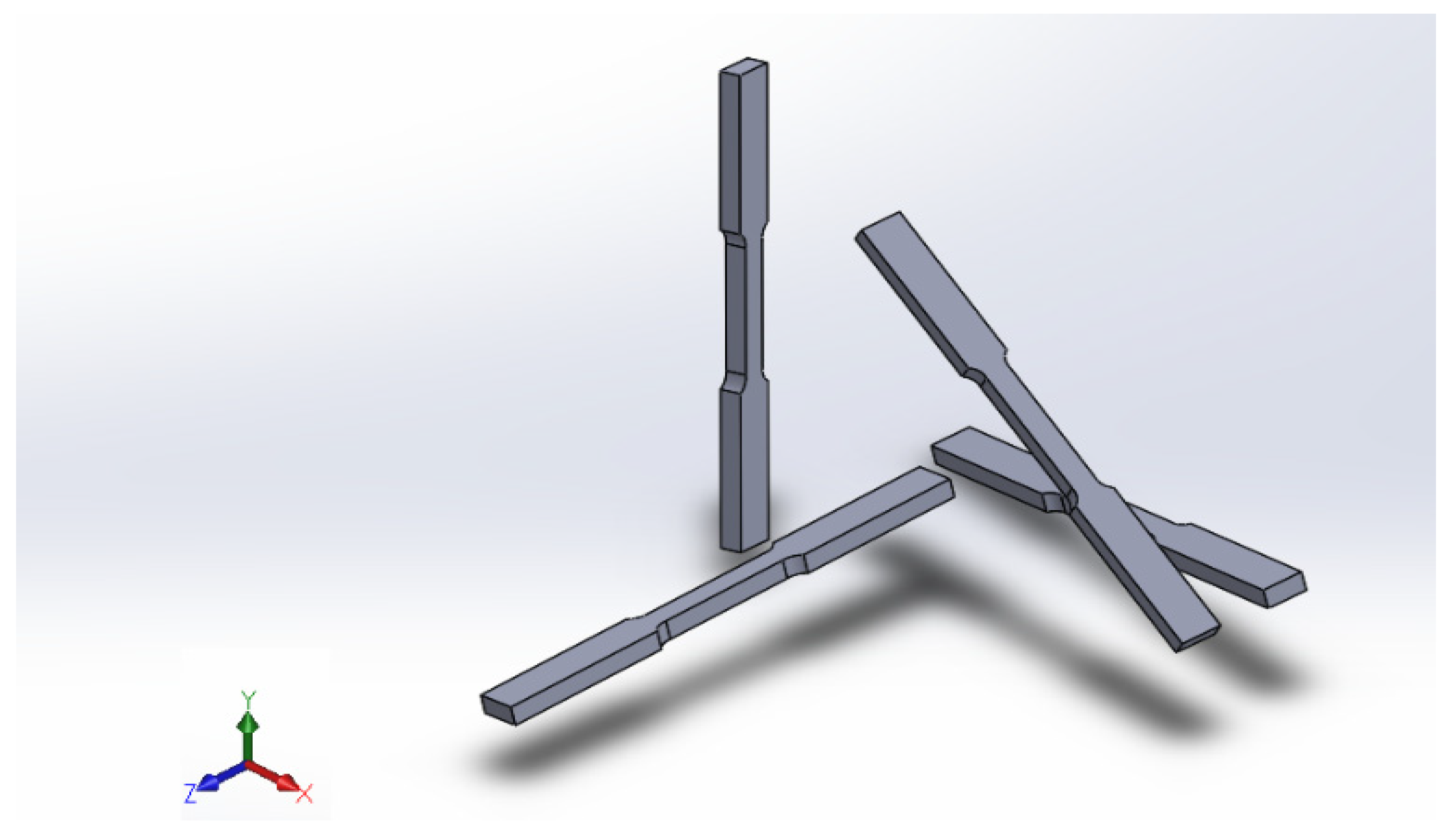
The SLM components were constructed for each bed orientation along X, Y, Z, and 45 degrees relative to the build platform (see Figure 1). Samples from each of these configurations were subjected to tensile tests and analyzed through acoustic emission.
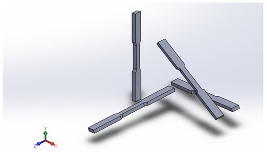
Figure 1.
Orientation of the specimens.
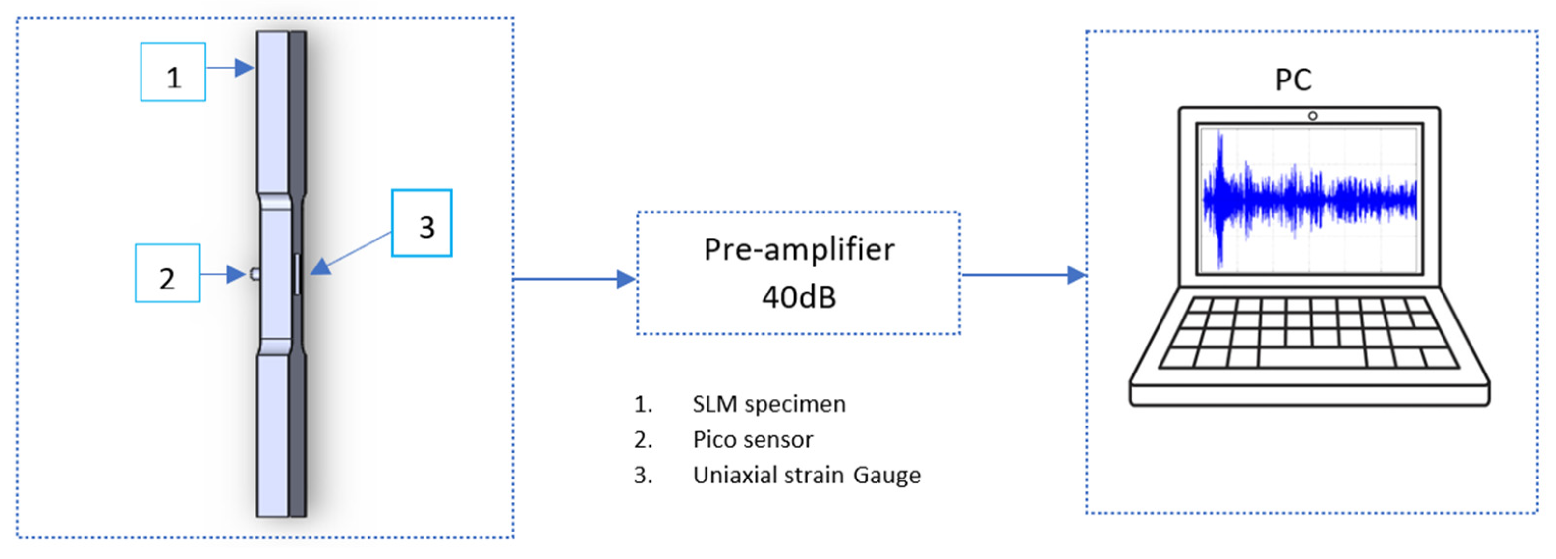
The thickness of each layer in the SLM process was 20 µm. The recoated layer was moved along the y-axis, while the laser scanned the samples along the X-axis. After scanning, the specimens were cooled in air and relaxed at 300 °C ± 10 °C for approximately 2 h. The dimensional data of all specimens built according to ASTM E8M are shown in Figure 2. The tensile tests were performed in the displacement-controlled mode at a speed of 1 mm/min in the INSTRON 1342 servo-hydraulic loading machine (10 kN). A uniaxial strain gauge was placed on the surface of the specimen, approximately in the middle of the gauge length. To monitor the acoustic activity under the load, the acoustic emission signal acquisition system was used, as shown in Figure 3. A broadband Pico sensor with an optimum operating frequency of 200–750 kHz and a resonance of 250 kHz was used to acquire the AE signals. The Pico sensor has a diameter of 5 mm × 4 mm and is positioned in the middle of the gauge length. The measured signals were preamplified with a 40 dB preamplifier. The signals were recorded at 2 MSPS before being filtered through 1 kHz low-pass and 3 MHz high-pass filters. These tensile tests are performed considering the orientation (Tx, Ty, Tz, T45) of the specimens as they are produced during the SLM process. The tests were performed on seven specimens each (Tx, Ty, Tz, T45), and the mechanical properties were extracted.

Figure 2.
Dimensions of specimens, as per ASTM E8M (mm).
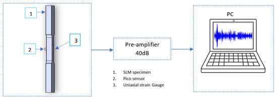
Figure 3.
Schematic of the acoustic emission setup.
2.2. Continuous Wavelet Transform Based on Acoustic Emission Signals
The continuous wavelet transform (CWT) is a signal processing technique which extracts the time domain content of acoustic emission signals [45]. The CWT has been successfully used to characterize damage modes in materials and structures. Grabowska et al. performed structural health monitoring (SHM) using AE and wavelet analysis [46]. Li et al. monitored damage in metal panel damage using AE and the adaptive enhancement variational mode decomposition wavelet packet transform [47]. Burud et al. detected damage in concrete subjected to bending using AE and wavelet entropy [48]. Baccar et al. detected wear using the acoustic emission wavelet analysis of AE [49].
The CWT is described by Equation (1).
where the mother wavelet described by Equation (2) is a parameter that determines the size of the wavelet. b sets the shift along the time axis and is decomposed into wavelet coefficients. Gao et al. provided more details of CWT [50]. In this paper, the Implementation CWT algorithm is performed on the MATLAB® (2022a) environment [45].
The ultimate principle is to apply the continuous wavelet transform (CWT), extract the time-frequency spectrograms of the acoustic emission signals, and then use these spectrograms as an image to train a convolutional neural network (CNN) for classification [43,44]. In this work, the characteristics of the acoustic emission signals collected during the tensile testing of the AlSi10Mg samples are also analyzed in time-frequency using CWT. A comparison of CNN architectures is performed. A new, simplified architecture is built in order to achieve similar performances in a shorter time.
2.3. Deep Convolutional Neural Network
The main element that constitutes a CNN is a chain of convolutional layers (Conv) with rectified linear unit activation functions (ReLu) (Sigmoid), maximum or average pooling layers (Max Pool, Avg Pool), and a fully connected layer. Stochastic gradient descent (SGD) and a batch normalization operation are typically used to train the models. Some authors built their models from scratch to solve various classification problems with the CNN [50,51]. Others based their models on the existing CNN and made some modifications to optimize the results of the classification [52,53].
This paper presents an exploration of the possibility of improving the accuracy of AlexNet (see Figure 4) and SqueezeNet. For a good modification, it is important to understand the main parameters that affect the accuracy of a CNN. Based on this understanding of the parameters and based on the challenges of two previous CNN models, a new model is proposed.

Figure 4.
AlexNet architecture.
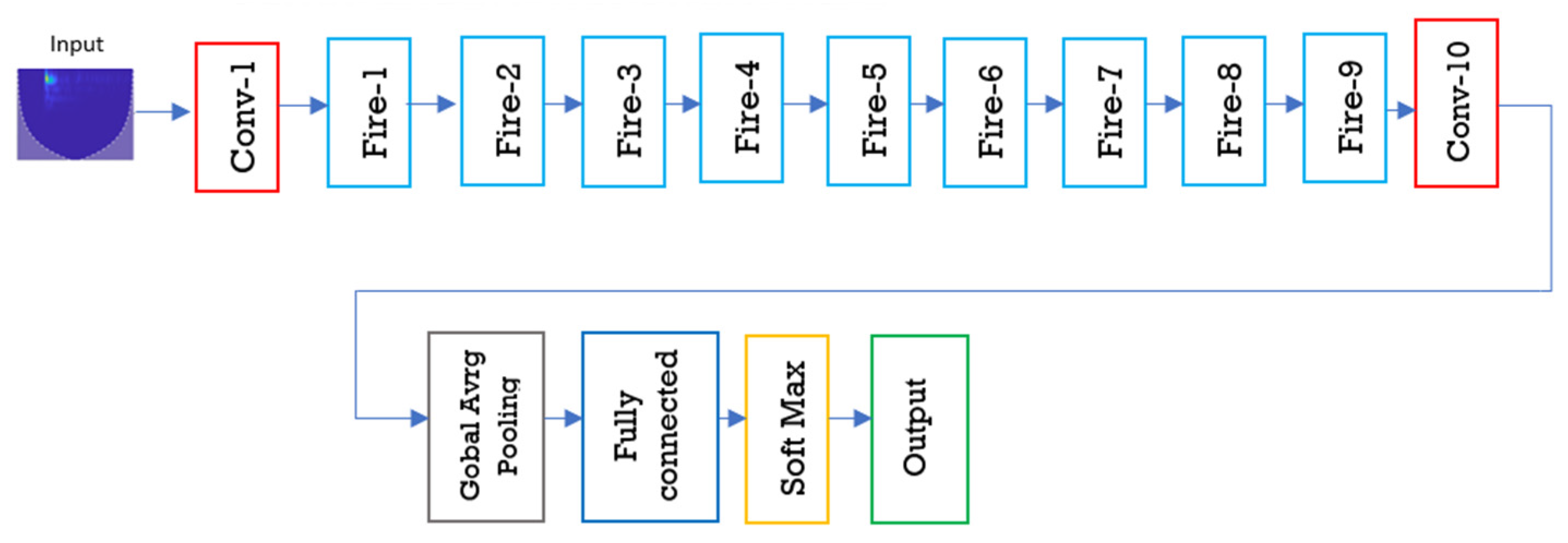
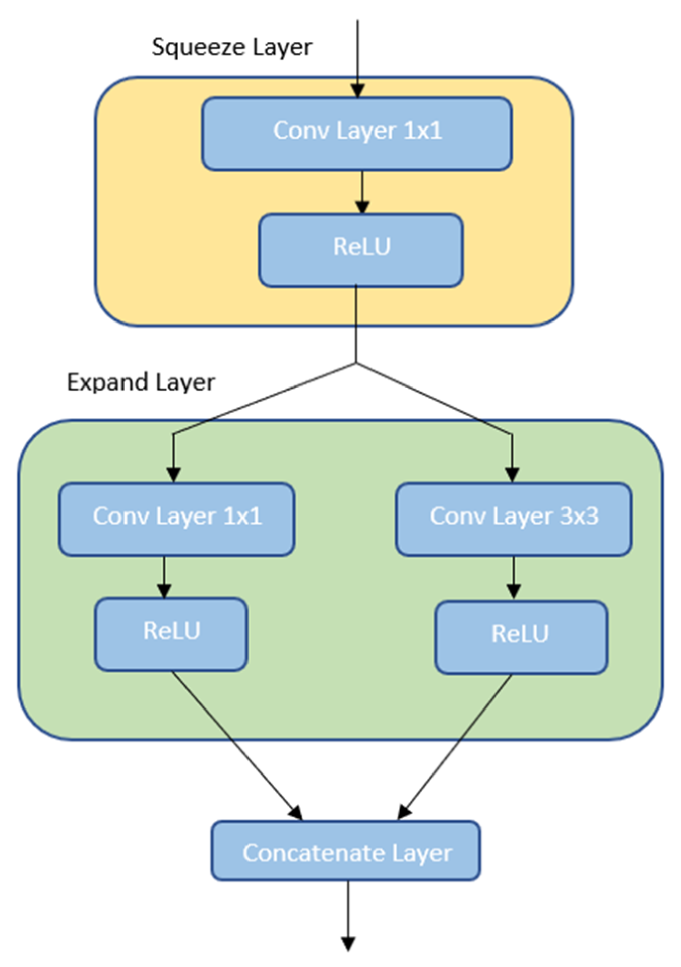
The ultimate goal was to have a small number of network parameters while maintaining a high level of accuracy. This is because a larger number of convolutional layers will result in a high accuracy but at the cost of greater time consumption and power [54]. Increasing the number of convolutional parameters results in obtaining lower error values during the training of the networks. Landola et al. claimed that SqueezeNet has 50× fewer parameters than AlexNet but can achieve about the same accuracy [55,56]. Its structure is based on the fire module, which allows the model to be compressed, as shown in Figure 5. The fire module consists of a squeeze convolutional layer with 1 × 1 filters feeding an expansion layer comprising a mixture of 1 × 1 and 3 × 3 convolutional filters. The integral structure is shown in Figure 6.
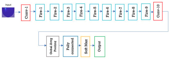
Figure 5.
SqueezeNet architecture.
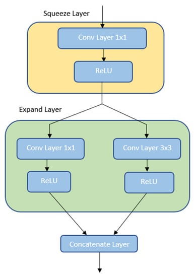
Figure 6.
Internal structure of the fire module in squeezeNet.
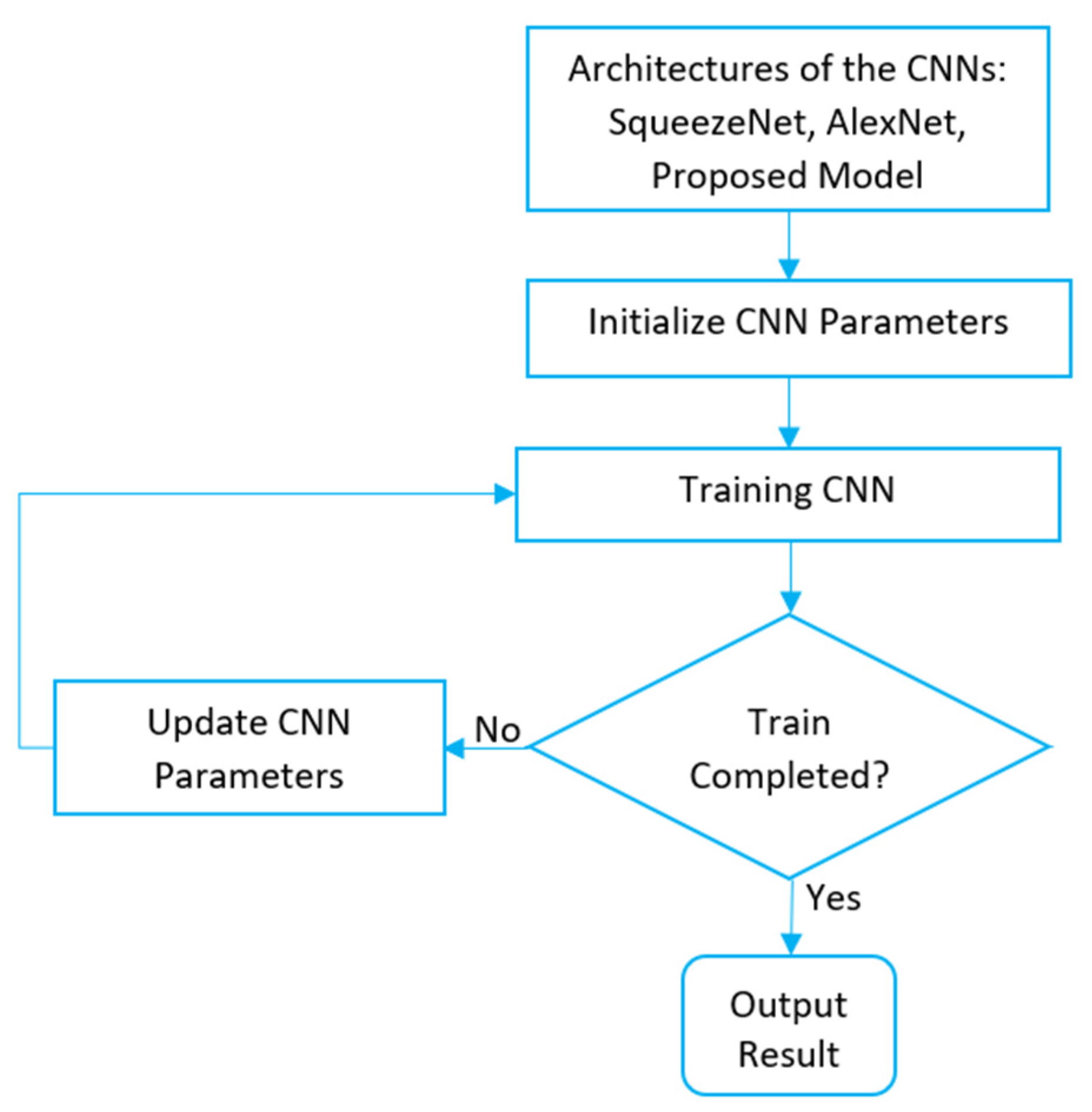
Considering the observations of Landola et al. [56] and Krizhevsky et al. [57] regarding the impact of the number of convolutional layers on the training and evaluation time of the CNN, a new model is proposed (Figure 7 and Table 2) that aims to reduce the number of parameters of the network without compromising its accuracy [58]. The main advantage of the model is the reduction of the parameters and the reduction of the development time of a CNN. In order to build this new model, to make a comparison with the previous models, alexNet and squeezeNet, and to understand which are the relevant parameters for a good model, several training modes are implemented following the approach proposed in Figure 8.

Figure 7.
New model build.

Table 2.
Configuration of the new model.
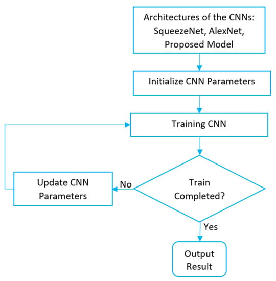
Figure 8.
Flowchart of the training mode.
3. Results and Discussions
3.1. Tensile Test Results
The mechanical properties, ultimate tensile strength, yield strength, Young’s modulus, and elongation at break of the specimens are presented in Table 3. The average and the standard deviation (Std_dev) are used to compare the mechanical properties.

Table 3.
Tensile test results of all the specimens.
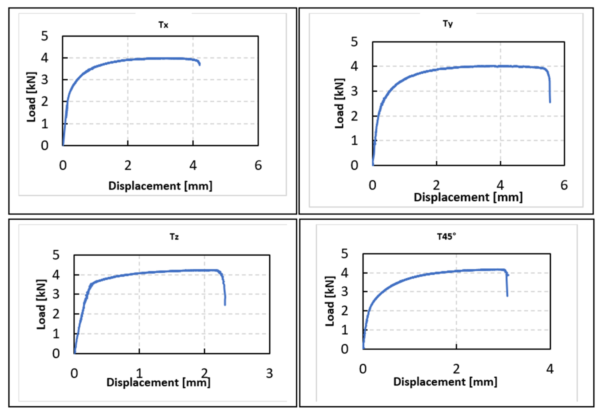
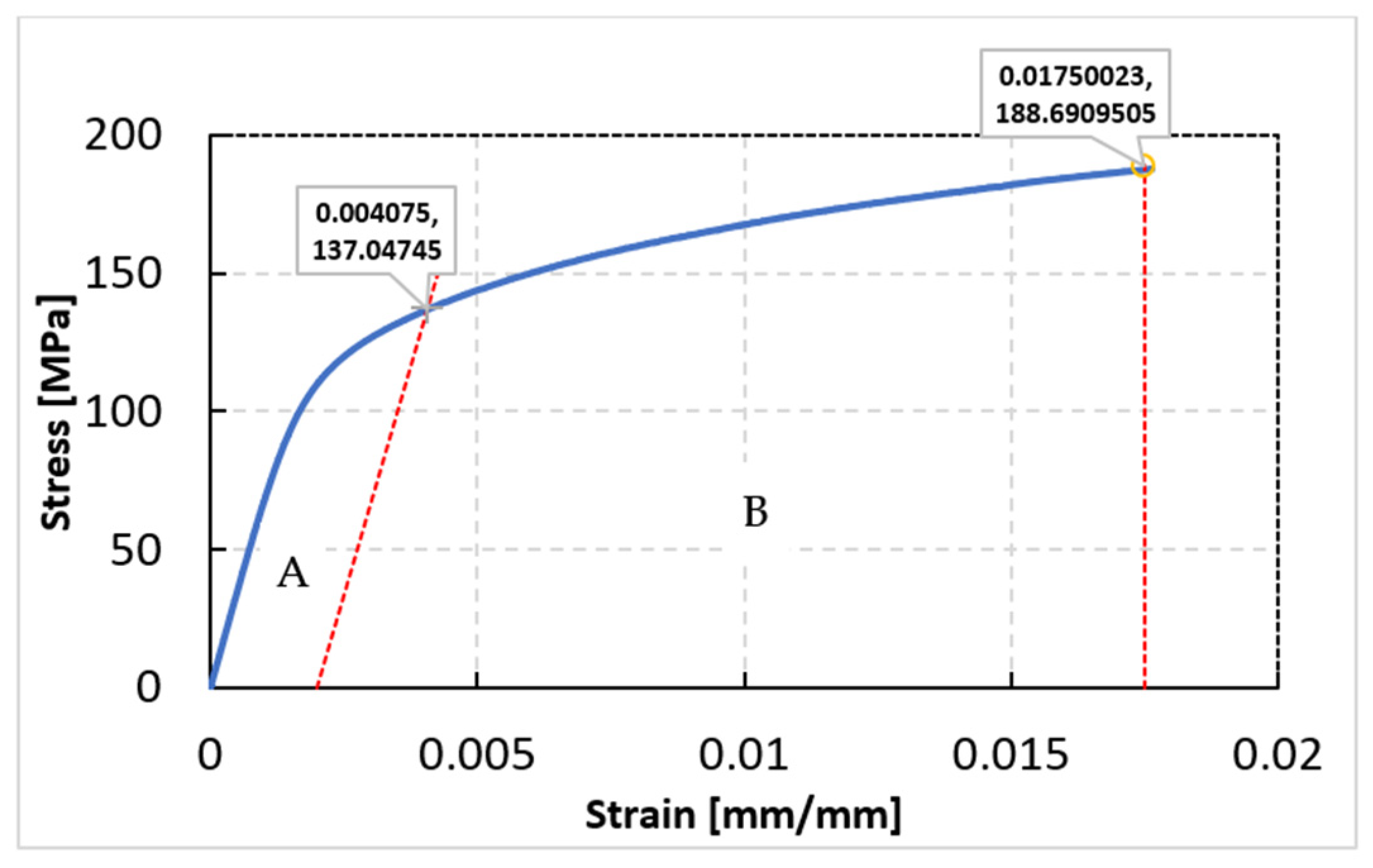
The results for the four groups of specimens are presented in Table 3. Certain observations were made, especially for the Tx and Ty groups of specimens. First, they exhibited similar mechanical properties. In addition, they exhibited a high yield strength compared to Tz and T45. Finally, the Tz group of specimens shows weak mechanical properties compared to Tx, Ty, and T45. Several authors have shown that the orientation of SLM components affects their anisotropy, microstructural heterogeneity, and mechanical properties [59,60]. Figure 9 shows the representative load-displacement curves for four different groups of specimens (Tx, Ty, Tz, and T45). Figure 10 shows two deformation stages considered in accordance with ASTM E8. The elastic limit is defined based on the stress–strain data. The first is elastic deformation, where the deformation is linear and reversible, and the stresses are less than or equal to the elastic limit. This phase considers the consolidation zone and the constriction zone, so the strain of the specimen before and after failure is considered. The average value of the proportion between the elastic limit and the ultimate limit for all specimens is 130 MPa to 184 MPa. The specimens in the Tx and Ty groups are quite similar, unlike those in the Tz and T45 groups. Acoustic emission signals are measured during both the elastic and plastic phases. A time-frequency analysis is performed, and several CNN models are built to classify the signals of the different damage stages.
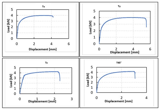
Figure 9.
Load-displacement curves of different groups of AlSi10Mg specimens (Tx, Ty, Tz, and T45).
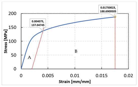
Figure 10.
(A) Elastic stage, (B) plastic stage considered for the AE analysis.
3.2. Damage Characterization Using the CWT of AE Signals
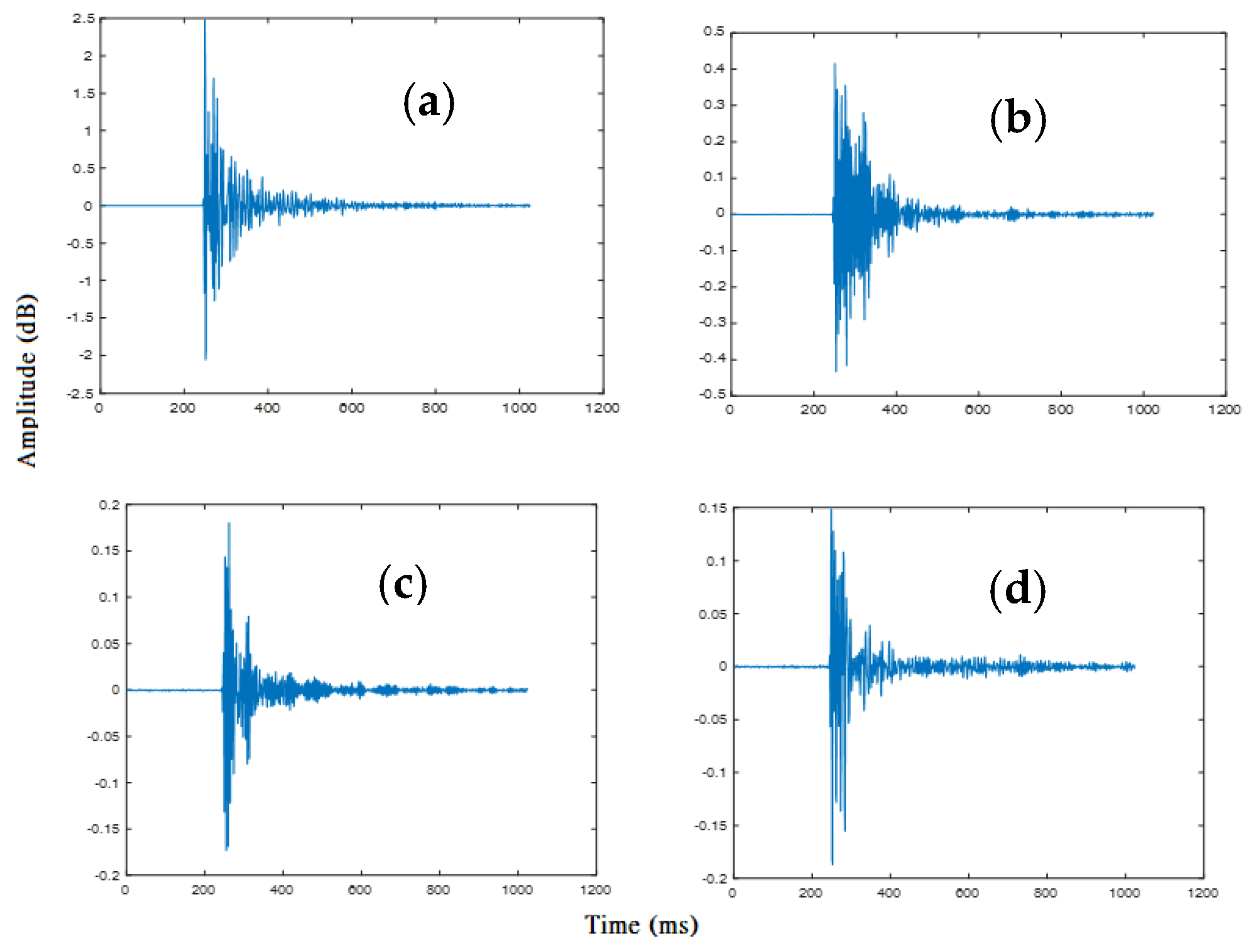
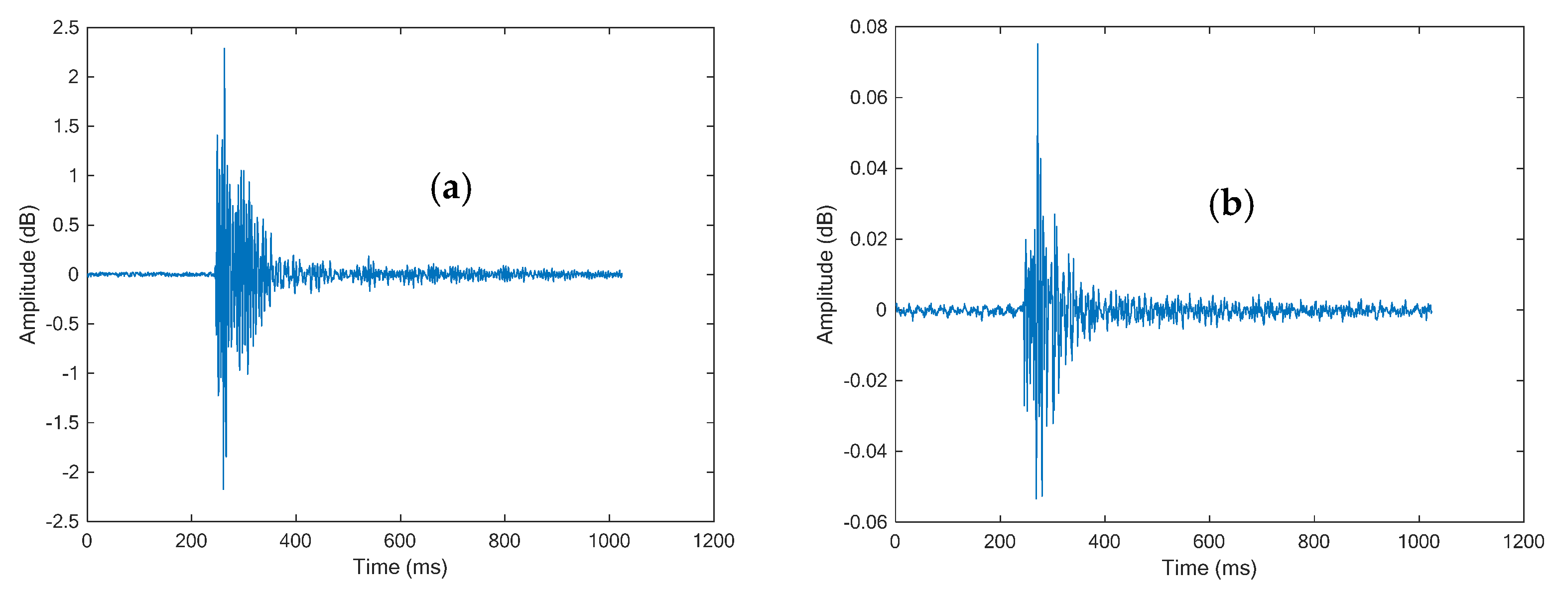
During the tensile test, the AE signals of four groups of specimens were extracted. Figure 11 shows the representative waveforms of the AE signals received from the specimens constructed in four different orientations. The waveforms of the AE signals characteristic of the elastic and plastic stages are presented in Figure 12.
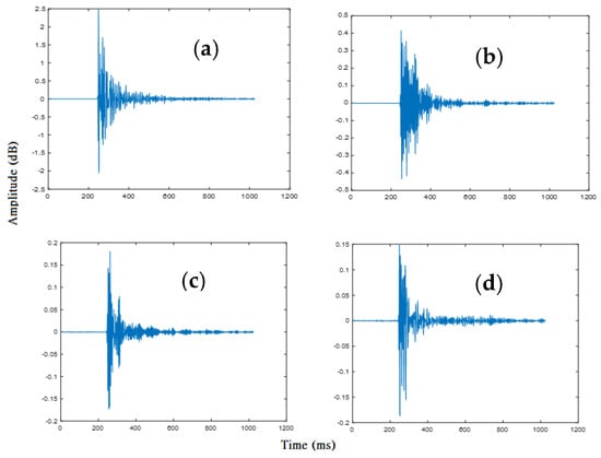
Figure 11.
Representative waveforms of the received AE signals for the specimens built in four different orientations: (a) Tx, (b) Ty, (c) Tz, (d) T45.
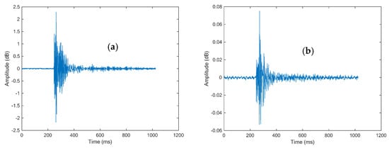
Figure 12.
(a) Representative waveforms of the AE signal from the Elastic Stage, (b) Representative waveforms of the AE signal from the Plastic Stage.
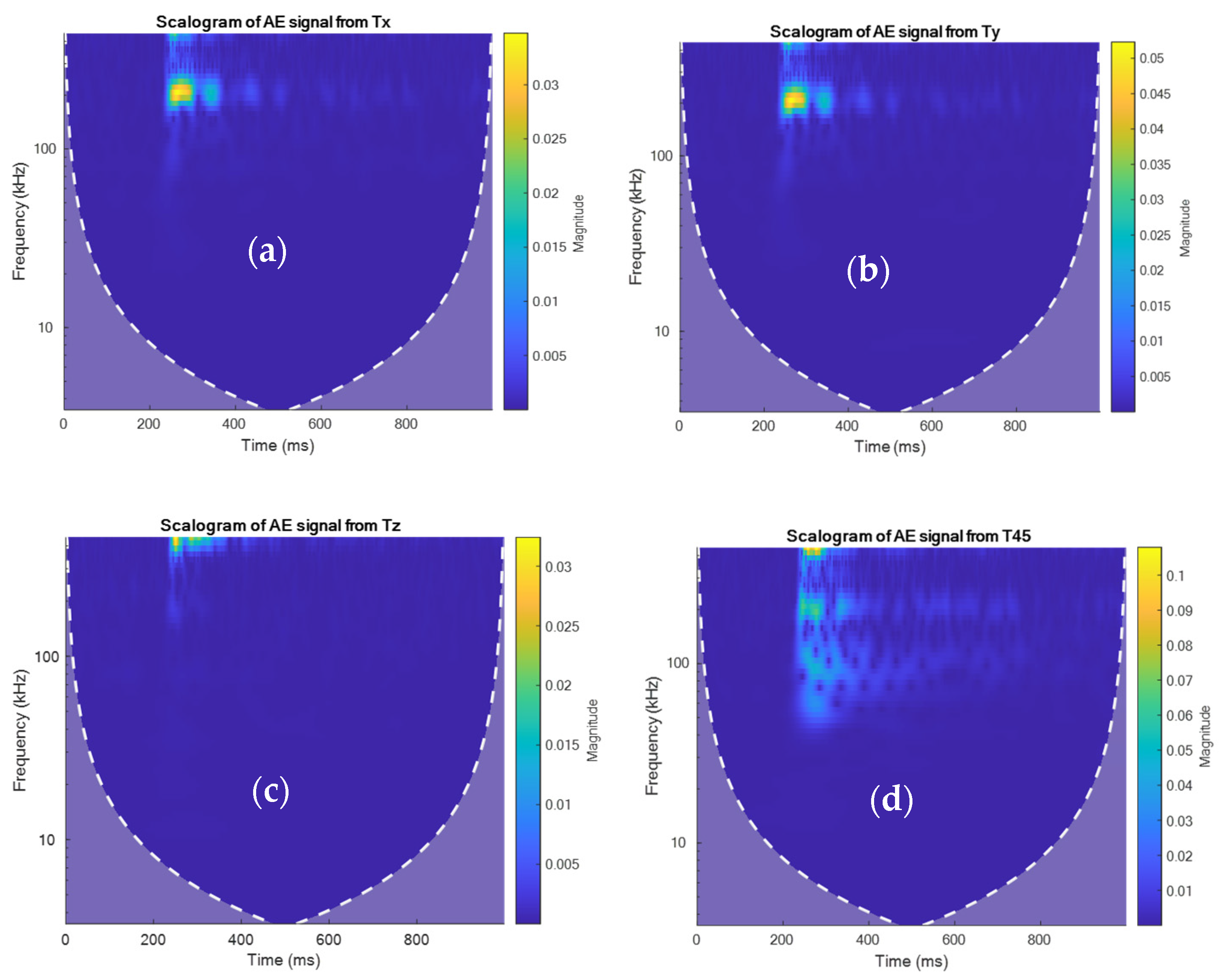
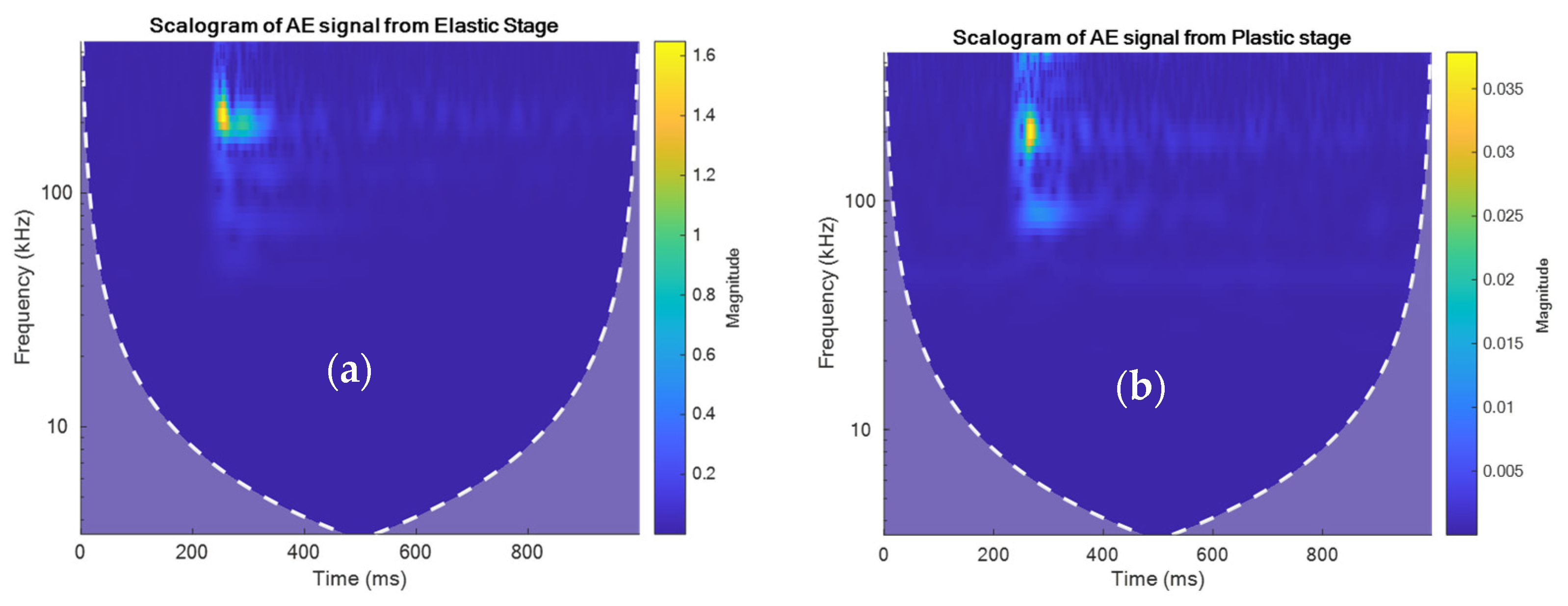
Figure 13 shows the spectrograms of the AE signals for four specimen orientations obtained with the CWT. The observation of the AE signals and the spectrogram revealed that Tx and Ty can be considered equivalent. By examining the spectral content within a given class, an order of magnitude of 0.005–0.3 is observed for Tx in the frequency range of 200–300 kHz (see Figure 13a). For Ty, in the same frequency range and time interval as Tx, the magnitude varies by 0.005–0.05 (see Figure 13b). For Tz, from 250 to 300 kHz, the magnitude varies from 0.05 to 0.03 (see Figure 13c). Finally, for T45, in the frequency range of 50–300kHz, the magnitude varies from 0.01 to 0.1 (see Figure 13d). A similarity is observed between the AE signals Tx and Ty, in contrast to the AE signals of Tz and T45. The same observation was made for the mechanical results of the tensile test (see Table 3). Figure 14 shows the scalogram of the different stages of elastic and plastic damage. During the elastic stage, a spectral energy is observed in the frequency range of 200 kHz to 300 kHz, varying in the order of 0.2–1.5 in terms of magnitude. A similar observation was made with the spectrogram of the plastic phase, where the frequency content is also found in the range of 200 kHz to 300 kHz, but a difference in magnitude of 0.005–0.04 is observed, which is considered small compared to the elastic stage (see Figure 14a,b).
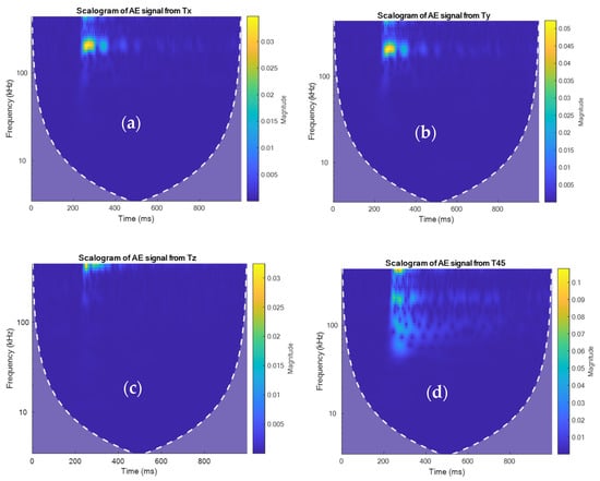
Figure 13.
(a) Spectrogram of the AE signal from Tx, (b) Spectrogram of the AE signal from Ty, (c) Spectrogram of the AE signal from Tz, and (d) Spectrogram of the AE signal from T45.
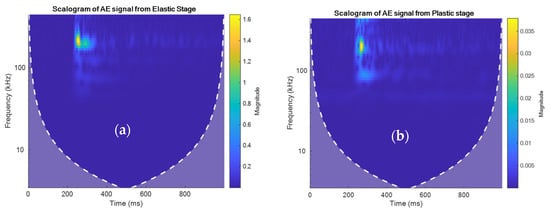
Figure 14.
(a) Spectrogram of the AE signal from the Elastic Stage, (b) Spectrogram of the AE signal from the Plastic Stage.
3.3. Damage Classification Using the Deep Learning Approach
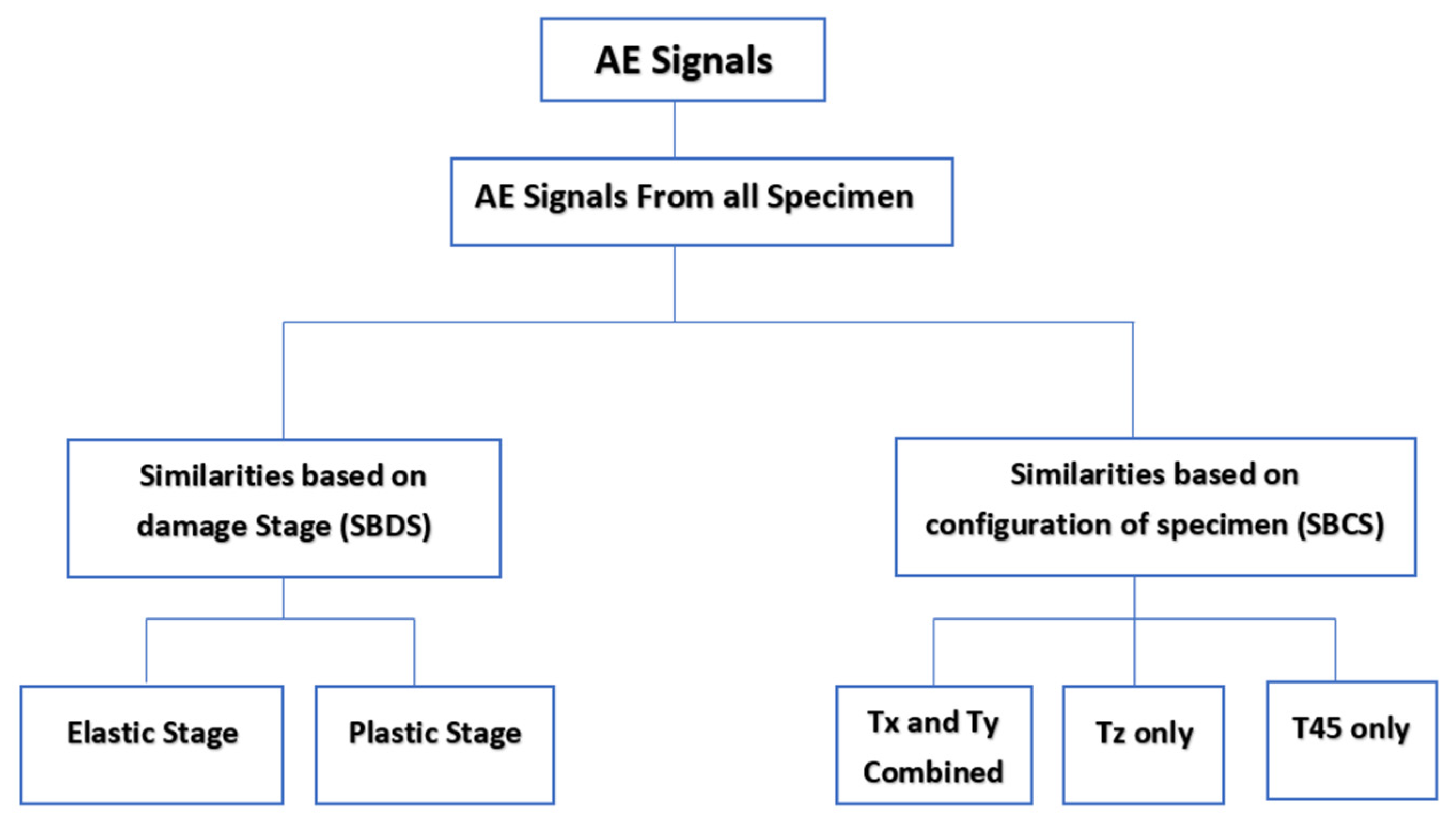
The analysis and processing of the AE signals collected during the tensile test have been explained in the previous section. These collected AE signals are analyzed by CWT in the time-frequency domain and visualized with the spectrogram. The frequency-time content made it possible to categorize the AE signals based on their similarities.
This categorization is shown in Figure 15. The CNN is used to efficiently classify groups of AE signals based on their similarities. The first mode analysis is used to make a comparison between the CNN models considered in this work (AlexNet, SqueezeNet, the new model). The second mode of analysis represent the contribution of a new, simple CNN model, but with better configurations. Finally, the minimum set achieves a better classification of AE signals. The stochastic gradient descent algorithm with momentum is used to train the CNNs. The initial learning rate is set to 0.0001, the maximum number of epochs for learning is 50, the mini batch has 30 elements, and there are three validation frequency observations. In order to achieve a better comparison of the results, the training, validation, and testing of the three different CNNs were performed in the same laptop with the configuration. The processor is 11th Gen Intel(R) Core i7-1195G7 and has a speed of 2.92 GHz, with 16.0 GB of RAM.
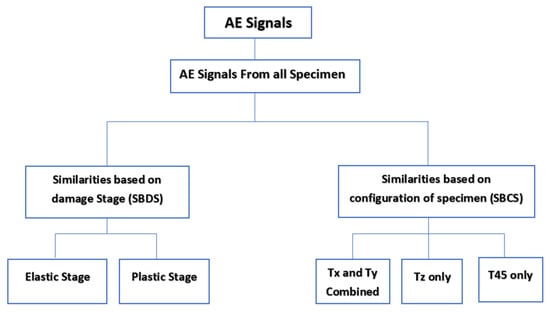
Figure 15.
Categorization of AE signals based on similarities.
The total number of images from each training mode is separated into three parts: 50% for training the CNN, 25% for validating its accuracy, and 25% for testing to rule out the overfitting of results.
3.3.1. Classification of AE Signals Based on the Damages Stage
AlexNet, SqueezeNet, and the proposed model were built on Matlab (2022a) using the Deep Network Designer Toolbox by Mathworks. Several training modes were performed to make a CNN comparison and determine the best configuration. Table 4 shows the results of classifying the AE signal groups based on the damage stages. Four training modes were tested for the three CNN models (alexNet, SqueezeNet, and the new model).

Table 4.
Classification of AE signals based on the damage stage.
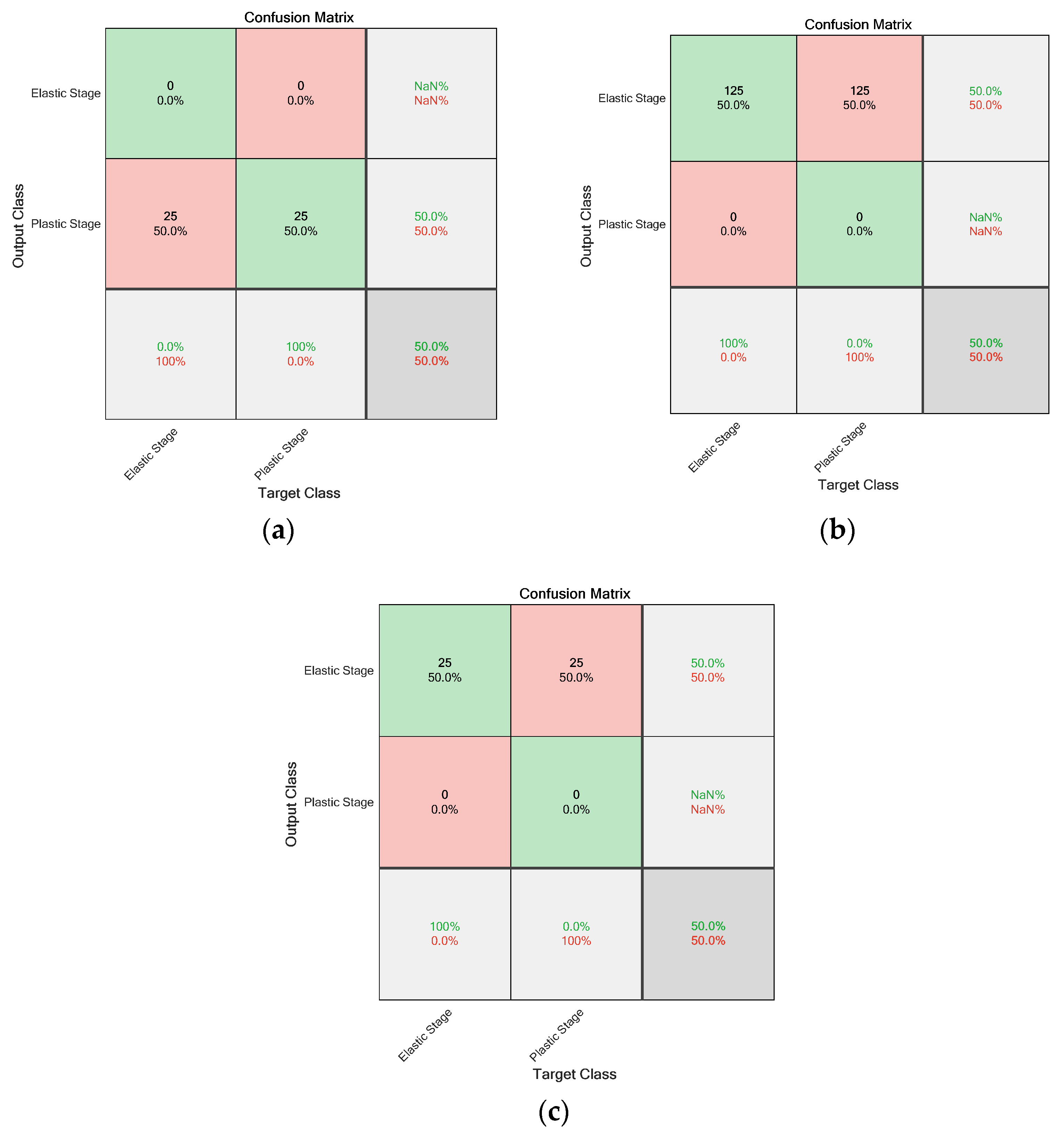
The first training mode, TM 1, used 200 image inputs, the sigmoid activation function, and average pooling for the pooling function. The results obtained are shown in Figure 16 for alexNet, SqueezeNet, and the new model, which are at 50% accuracy. An observation was made on the training time of each CNN: alexNet—56 min 28 s, squeezeNet—46 min 04 s, the new model—26 min 46 s.
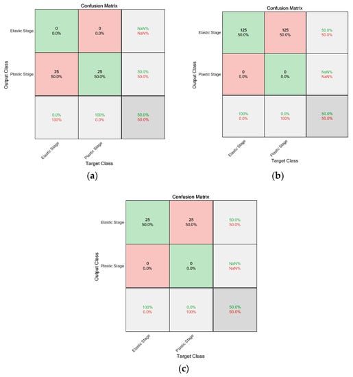
Figure 16.
Classification based on the damage stage using TM 1: (a) AlexNet, (b) SqueezeNet, and (c) Proposed model CNN.
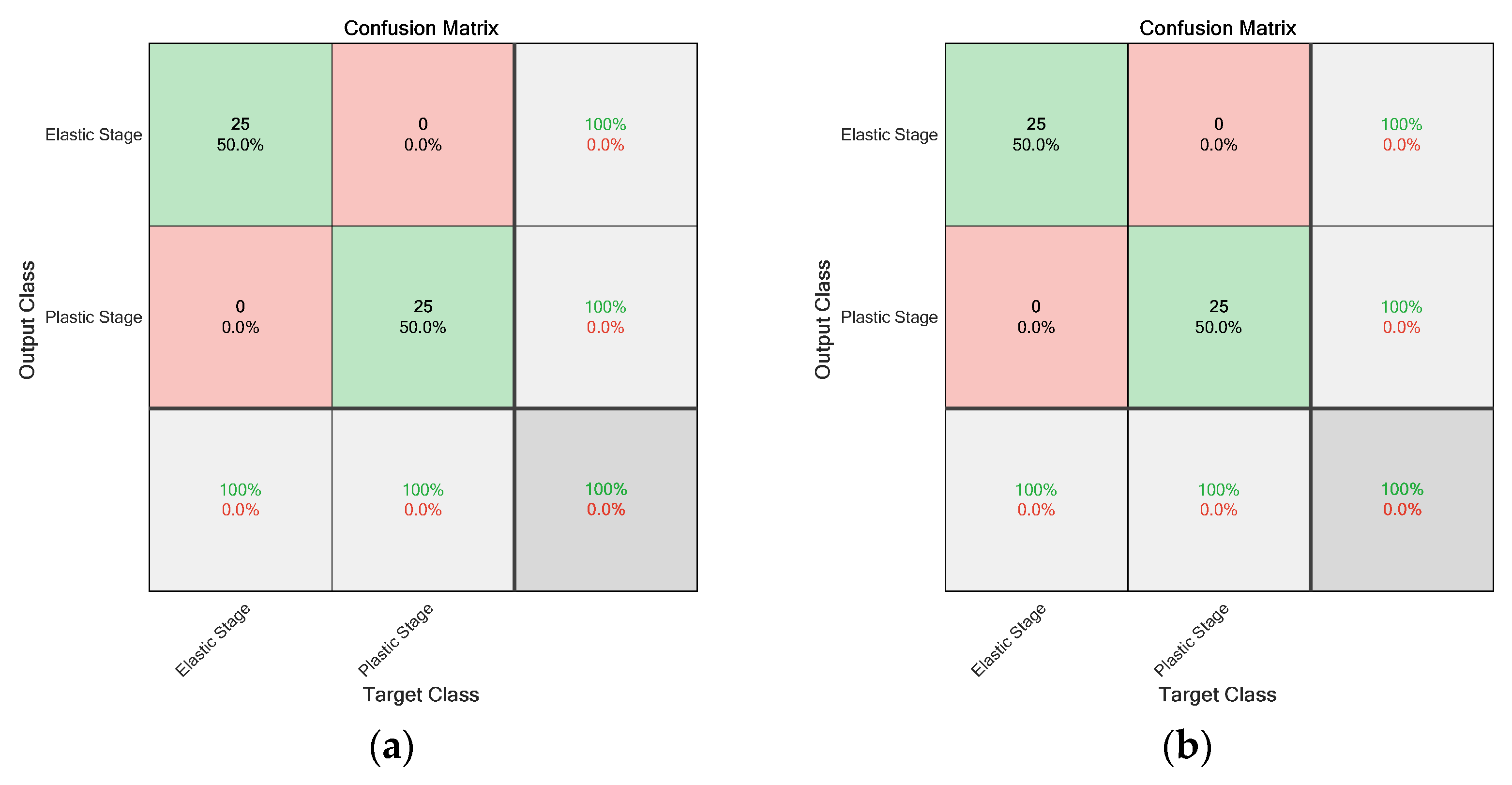
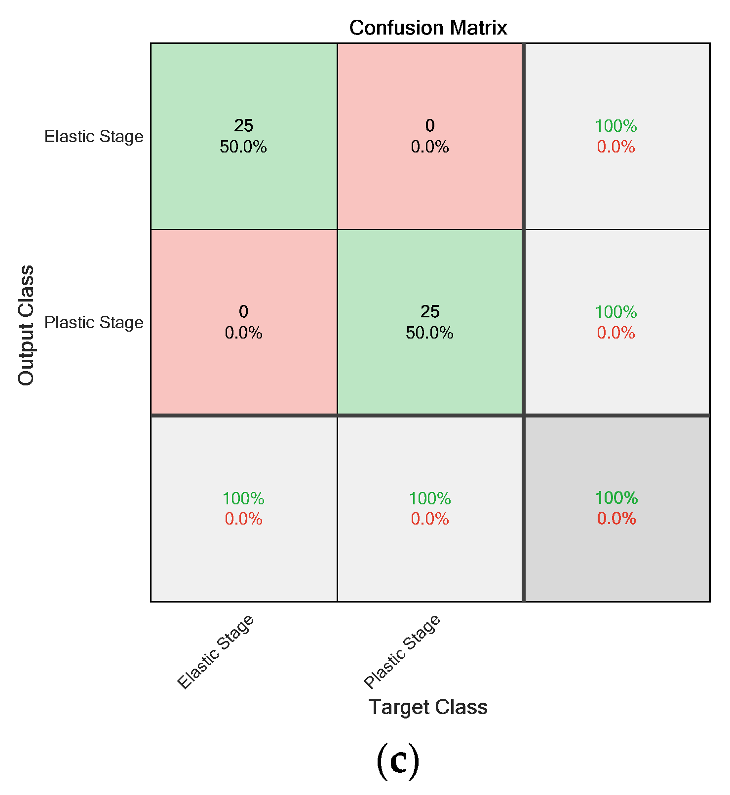
For the second mode, TM 2, all parameters were kept the same as in the first training mode, except for the activation function, which was changed from Sigmoid to ReLu. The results are shown in Table 4 and Figure 17. By changing the activation function, the accuracy of all CNN models reached the maximum value of 100%. The difference in training time was observed for each model: AlexNet—40 min 27 s, squeezeNet—25 min 45 s, and the new model—19 min 22 s. In addition, the training time for each CNN model decreased by about 20% when the ReLu activation function was used.
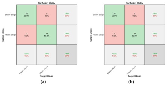
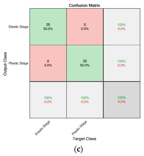
Figure 17.
Classification based on the damage stage using TM 2: (a) AlexNet, (b) SqueezeNet, and (c) Proposed model CNN.
For the third training mode, TM 3, the same parameters were used as for the first mode, but with a higher image input of 1000. Thus, 500 input images were used for each class (the elastic and plastic stages). The results shown in Table 4 show that AlexNet achieved 50% accuracy, SqueezeNet achieved 48.7%, and the new model achieved 50%. The development time increased with the amount of input data: 3 h 29 min for AlexNet, 2 h 57 min for SqueezeNet, and 1 h 46 min for the new model.
The fourth training mode, TM 4, used 1000 images with the ReLu activation function. The results obtained are presented in Table 4, where 100% accuracy was achieved for all CNN models. The processing time for alexNet is 2 h 07 min, for SqueezeNet, it is 61 min 16 s, and for the new model, it is 36 min 32 s.
Based on all the training modes performed to automatically classify the damage stages of AlSi10Mg specimens, a few observations were made. First, the training time of AlexNet is greater than that of squeezeNet and the new model, especially for the high number of parameters [61]. Secondly, the ReLu activation function converges quickly and therefore takes much less time than the models trained with the sigmoid function. The sigmoid activation function is a fraction between 0 and 1. As the layers multiply, the global gradient becomes exponentially small, so each step along the gradient causes only a tiny change to the weights [62]. With ReLu activation, on the other hand, the gradient is either 0 or 1, so the global gradient is neither too small nor too large [63].
3.3.2. Classification of AE Signals Based on the Configuration of the Specimen
The same observation was made for the AE signals categorized based on their configurations (Txy, Tz, T45). Looking at the results presented in Table 5, a simultaneity is observed with the first damage-based categorization, where the accuracy increases when the sigmoid activation function is replaced with ReLu. Again, let us observe that the accuracy is still 33.3% lower for AE signals from different specimen orientations. By increasing the input data, a particular observation was made on the new model, the accuracy increases by 66.7% compared to alexNet and SqueezeNet. Finally, by changing the sigmoid activation function to ReLu, an accuracy of 100% is achieved.

Table 5.
Classification of AE signals based on the configuration of the specimen.
3.3.3. Classification of AE Signals from Individual Specimens
In this section, the group of AE signals originating from an individual specimen is classified in terms of their configuration (Tx, Ty, Tz, and T45). Based on the previous result (see Table 5), the ReLu activation function has been shown to be effective in classifying the AE signals. Based on this optimal configuration of CNNs, this section examines the amount of data needed to train a CNN to achieve 100% accuracy.
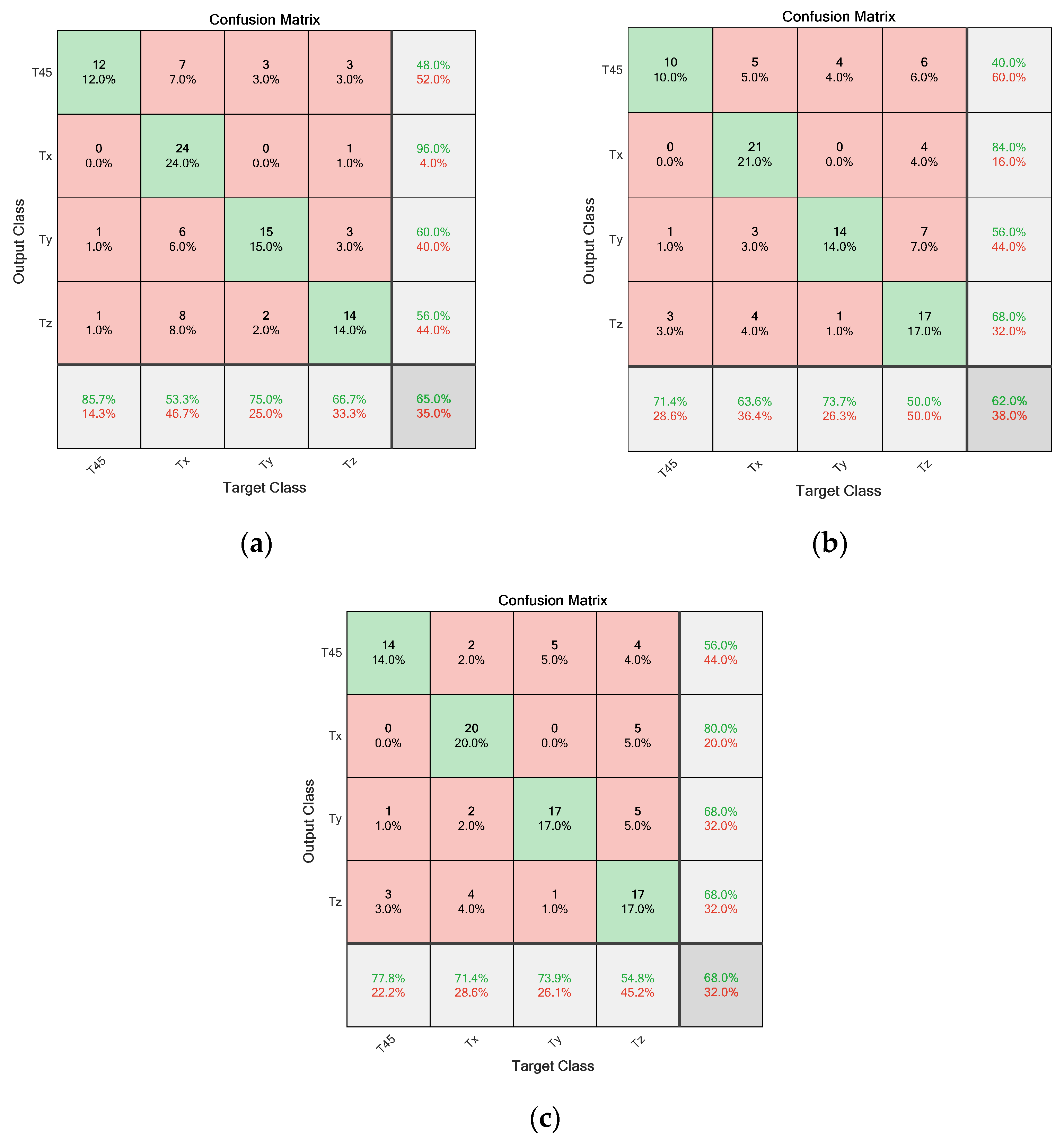
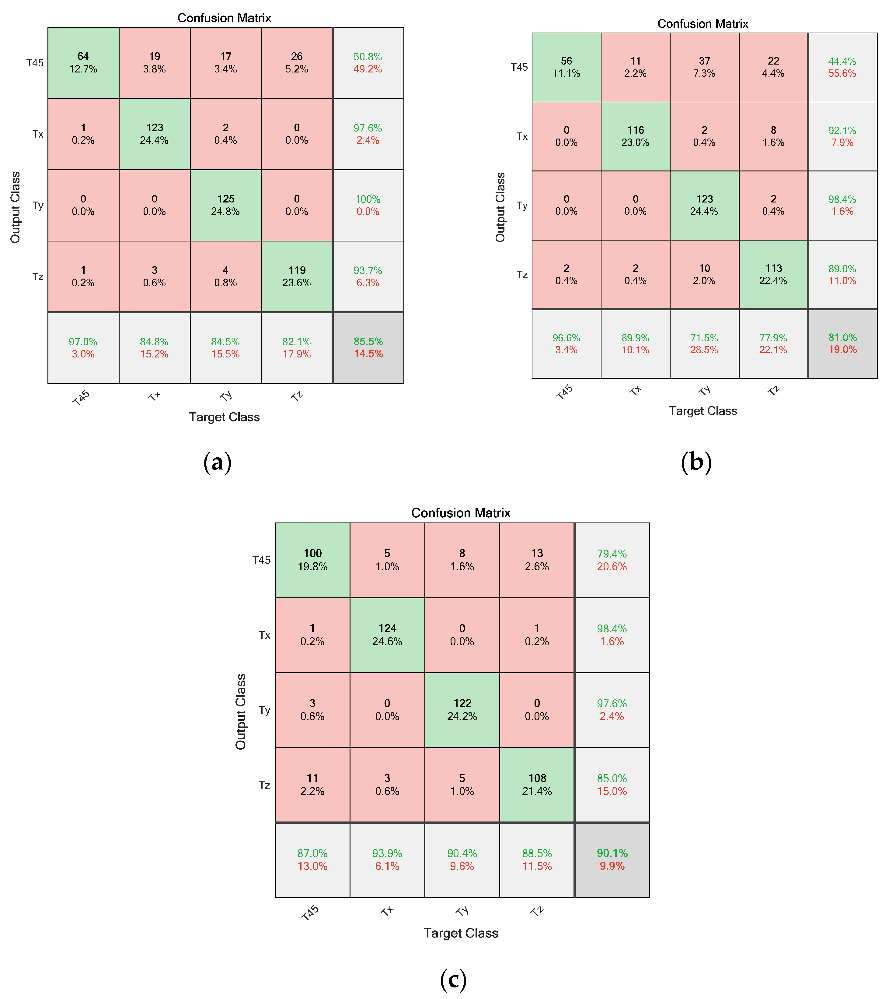
The results are shown in Table 6. In the first training mode, TM 1, 400 input data were used, considering 100 per class (Tx, Ty, Tz, and T45) using the ReLu activation function. Figure 18 shows the results for alexNet (65.0%), squeezeNet (62.0%) and the new model (68.0% accuracy). The processing time behaves the same as the previous result. Finally, when the input images are increased from 400 to 2000 at a rate of 500 per class, an improvement is seen, which is 85.5% for alexNet, 81.1% for squeezeNet, and 90.1% for the new model (see Figure 19). Thus, for the best CNN configurations, the amount of input data affects the classification accuracy. A simplified CNN model can have better classification accuracy.

Table 6.
Classification of AE signals from individual specimens based on the configuration.
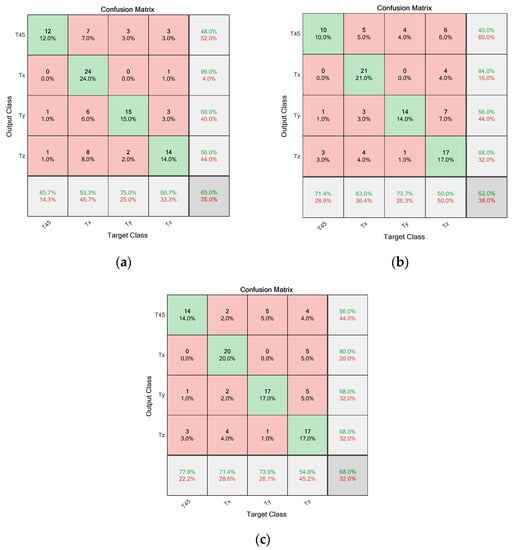
Figure 18.
Classification based on the signals generated from individual specimens using TM 1: (a) AlexNet, (b) SqueezeNet, and (c) the Proposed model CNN.
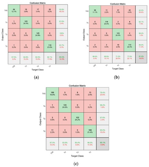
Figure 19.
Classification based on the signals generated from individual specimens using TM 2: (a) AlexNet, (b) SqueezeNet, and (c) the Proposed model CNN.
4. Conclusions
This paper proposes a deep learning approach based on AE data. The objective is to characterize and classify different stages of deformation (elastic and plastic) and different configurations of the specimen (Txy, Tz, T45) on AlSi10Mg samples obtained during the SLM process. The process started with tensile tests. The AE signals were extracted. A time-frequency analysis was performed, using CWT to extract the spectrograms. The time-frequency content allowed the AE signals to be distinguished from the stages of damage (elastic and plastic) and from the different configurations of the specimen. Subsequently, these spectrograms were used to train three different CNNs, including AlexNet, SqueezeNet, and a new model. A comparison was made among these three CNN models, considering the accuracy and development time of the different CNN models. In addition, a series of training modes were performed to determine the amount of data required to train a network to achieve 100% accuracy. Changing the parameters from Max-Pooling to Average-Pooling does not affect the results. Using the sigmoid activation function results in 50% accuracy for the damage stage classification and 33.3% accuracy for the classification based on the specimen configuration for all the CNN models used. Using the ReLu activation function, 100% accuracy is achieved for each CNN model. The CNN achieves the same accuracy but with a different learning time. The new, simplified CNN model classified AE signals in less time compared to AlexNet and squeezeNet, which have a high number of parameters. The AE signals, which are from an individual specimen, were classified with the optimal CNNs by changing the input data. The results show, first, that increasing the input data affects the accuracy of CNN classification. Second, the simplified CNN model can achieve the same accuracy as AlexNet and squeezeNet but in a short time.
Author Contributions
Conceptualization, C.B., G.P., V.P.K. and D.K.M.; methodology, C.B., G.P., V.P.K. and D.K.M.; software, D.K.M.; validation, C.B., G.P., V.P.K. and D.K.M.; formal analysis, C.B., G.P., V.P.K. and D.K.M.; investigation, C.B., G.P., V.P.K. and D.K.M.; resources, C.B. and G.P.; data curation, C.B., V.P.K. and D.K.M.; writing—original draft preparation, D.K.M.; writing—review and editing, C.B., G.P., V.P.K. and D.K.M.; visualization, D.K.M.; supervision, G.P. and C.B.; project administration, G.P. and C.B.; funding acquisition, C.C. All authors have read and agreed to the published version of the manuscript.
Funding
This research received no external funding.
Institutional Review Board Statement
Not applicable.
Informed Consent Statement
Not applicable.
Data Availability Statement
Not applicable.
Conflicts of Interest
The authors declare no conflict of interest.
References
- Zhao, L.; Santos Macías, J.G.; Ding, L.; Idrissi, H.; Simar, A. Damage Mechanisms in Selective Laser Melted AlSi10Mg under as Built and Different Post-Treatment Conditions. Mater. Sci. Eng. A 2019, 764, 138210. [Google Scholar] [CrossRef]
- Uhlmann, E.; Kersting, R.; Klein, T.B.; Cruz, M.F.; Borille, A.V. Additive Manufacturing of Titanium Alloy for Aircraft Components. Procedia CIRP 2015, 35, 55–60. [Google Scholar] [CrossRef]
- Yadroitsev, I.; Krakhmalev, P.; Yadroitsava, I. Selective Laser Melting of Ti6Al4V Alloy for Biomedical Applications: Temperature Monitoring and Microstructural Evolution. J. Alloys Compd. 2014, 583, 404–409. [Google Scholar] [CrossRef]
- Singh, S.; Ramakrishna, S.; Singh, R. Material Issues in Additive Manufacturing: A Review. J. Manuf. Process. 2017, 25, 185–200. [Google Scholar] [CrossRef]
- Ngo, T.D.; Kashani, A.; Imbalzano, G.; Nguyen, K.T.Q.; Hui, D. Additive Manufacturing (3D Printing): A Review of Materials, Methods, Applications and Challenges. Compos. B Eng. 2018, 143, 172–196. [Google Scholar] [CrossRef]
- Barile, C.; Casavola, C.; Moramarco, V.; Vimalathithan, P.K. A Comprehensive Study of Mechanical and Acoustic Properties of Selective Laser Melting Material. Arch. Civ. Mech. Eng. 2019, 1, 3. [Google Scholar] [CrossRef]
- Gu, D.; Wang, Z.; Shen, Y.; Li, Q.; Li, Y. In-Situ TiC Particle Reinforced Ti–Al Matrix Composites: Powder Preparation by Mechanical Alloying and Selective Laser Melting Behavior. Appl. Surf. Sci. 2009, 255, 9230–9240. [Google Scholar] [CrossRef]
- Amato, K.N.; Gaytan, S.M.; Murr, L.E.; Martinez, E.; Shindo, P.W.; Hernandez, J.; Collins, S.; Medina, F. Microstructures and Mechanical Behavior of Inconel 718 Fabricated by Selective Laser Melting. Acta Mater. 2012, 60, 2229–2239. [Google Scholar] [CrossRef]
- Geiger, F.; Kunze, K.; Etter, T. Tailoring the Texture of IN738LC Processed by Selective Laser Melting (SLM) by Specific Scanning Strategies. Mater. Sci. Eng. A 2016, 661, 240–246. [Google Scholar] [CrossRef]
- Ma, M.; Wang, Z.; Zeng, X. A Comparison on Metallurgical Behaviors of 316L Stainless Steel by Selective Laser Melting and Laser Cladding Deposition. Mater. Sci. Eng. A 2017, 685, 265–273. [Google Scholar] [CrossRef]
- Wang, D.; Song, C.; Yang, Y.; Bai, Y. Investigation of Crystal Growth Mechanism during Selective Laser Melting and Mechanical Property Characterization of 316L Stainless Steel Parts. Mater. Des. 2016, 100, 291–299. [Google Scholar] [CrossRef]
- Rao, H.; Giet, S.; Yang, K.; Wu, X.; Davies, C.H.J. The Influence of Processing Parameters on Aluminium Alloy A357 Manufactured by Selective Laser Melting. Mater. Des. 2016, 109, 334–346. [Google Scholar] [CrossRef]
- Wu, J.; Wang, X.Q.; Wang, W.; Attallah, M.M.; Loretto, M.H. Microstructure and Strength of Selectively Laser Melted AlSi10Mg. Acta Mater. 2016, 117, 311–320. [Google Scholar] [CrossRef]
- Aversa, A.; Lorusso, M.; Cattano, G.; Manfredi, D.; Calignano, F.; Ambrosio, E.P.; Biamino, S.; Fino, P.; Lombardi, M.; Pavese, M. A Study of the Microstructure and the Mechanical Properties of an AlSiNi Alloy Produced via Selective Laser Melting. J. Alloys Compd. 2017, 695, 1470–1478. [Google Scholar] [CrossRef]
- Gupta, A.K.; Lloyd, D.J.; Court, S.A. Precipitation Hardening in Al-Mg-Si Alloys with and without Excess Si. Mater. Sci. Eng. A 2001, 316, 11–17. [Google Scholar] [CrossRef]
- Thijs, L.; Kempen, K.; Kruth, J.P.; van Humbeeck, J. Fine-Structured Aluminium Products with Controllable Texture by Selective Laser Melting of Pre-Alloyed AlSi10Mg Powder. Acta Mater. 2013, 61, 1809–1819. [Google Scholar] [CrossRef]
- Kempen, K.; Thijs, L.; van Humbeeck, J.; Kruth, J.P. Mechanical Properties of AlSi10Mg Produced by Selective Laser Melting. Phys. Procedia 2012, 39, 439–446. [Google Scholar] [CrossRef]
- Patakham, U.; Palasay, A.; Wila, P.; Tongsri, R. MPB Characteristics and Si Morphologies on Mechanical Properties and Fracture Behavior of SLM AlSi10Mg. Mater. Sci. Eng. A 2021, 821, 141602. [Google Scholar] [CrossRef]
- Dong, Z.; Liu, Y.; Li, W.; Liang, J. Orientation Dependency for Microstructure, Geometric Accuracy and Mechanical Properties of Selective Laser Melting AlSi10Mg Lattices. J. Alloys Compd. 2019, 791, 490–500. [Google Scholar] [CrossRef]
- Maconachie, T.; Leary, M.; Zhang, J.; Medvedev, A.; Sarker, A.; Ruan, D.; Lu, G.; Faruque, O.; Brandt, M. Effect of Build Orientation on the Quasi-Static and Dynamic Response of SLM AlSi10Mg. Mater. Sci. Eng. A 2020, 788, 139445. [Google Scholar] [CrossRef]
- Kok, Y.; Tan, X.P.; Wang, P.; Nai, M.L.S.; Loh, N.H.; Liu, E.; Tor, S.B. Anisotropy and Heterogeneity of Microstructure and Mechanical Properties in Metal Additive Manufacturing: A Critical Review. Mater. Des. 2018, 139, 565–586. [Google Scholar] [CrossRef]
- Beretta, S.; Gargourimotlagh, M.; Foletti, S.; du Plessis, A.; Riccio, M. Fatigue Strength Assessment of “as Built” AlSi10Mg Manufactured by SLM with Different Build Orientations. Int. J. Fatigue 2020, 139, 105737. [Google Scholar] [CrossRef]
- Tetelman, A.; Chow, R. Acoustic Emission Testing and Microfracture Processes. Undefined 1971, 30, 30–40. [Google Scholar] [CrossRef]
- Grosse, C.U.; Ohtsu, M.; Aggelis, D.G.; Shiotani, T. (Eds.) Acoustic Emission Testing; Springer Nature: Berlin, Germany, 2022. [Google Scholar] [CrossRef]
- Ito, K.; Kusano, M.; Demura, M.; Watanabe, M. Detection and Location of Microdefects during Selective Laser Melting by Wireless Acoustic Emission Measurement. Addit. Manuf. 2021, 40, 101915. [Google Scholar] [CrossRef]
- Barile, C.; Casavola, C.; Pappalettera, G.; Kannan, V.P.; Renna, G. Acoustic Emission Signal Processing for the Assessment of Corrosion Behaviour in Additively Manufactured AlSi10Mg. Mech. Mater. 2022, 170, 104347. [Google Scholar] [CrossRef]
- Barile, C.; Casavola, C.; Pappalettera, G.; Vimalathithan, P.K. Acoustic Emission Descriptors for the Mechanical Behavior of Selective Laser Melted Samples: An Innovative Approach. Mech. Mater. 2020, 148, 103448. [Google Scholar] [CrossRef]
- Ould Amer, A.; Gloanec, A.L.; Courtin, S.; Touze, C. Characterization of Fatigue Damage in 304L Steel by an Acoustic Emission Method. Procedia Eng. 2013, 66, 651–660. [Google Scholar] [CrossRef]
- Barile, C.; Casavola, C.; Cazzato, A. Materials Acoustic Emissions in 3D Printed Parts under Mode I Delamination Test. Materials 2018, 11, 1760. [Google Scholar] [CrossRef]
- Barile, C.; Casavola, C.; Pappalettera, G.; Pappalettere, C. Fatigue Damage Monitoring by Means of Acoustic Emission and Thermography in Ti Grade 5 Specimens. Procedia Eng. 2015, 114, 487–492. [Google Scholar] [CrossRef]
- Venkatesan, R.; Li, B. Convolutional Neural Networks in Visual Computing: A Concise Guide; CRC Press: Boca Raton, FL, USA, 2017; 186p. [Google Scholar] [CrossRef]
- Ramasamy, P.; Sampathkumar, S. Prediction of Impact Damage Tolerance of Drop Impacted WGFRP Composite by Artificial Neural Network Using Acoustic Emission Parameters. Compos. B Eng. 2014, 60, 457–462. [Google Scholar] [CrossRef]
- Lu, D.; Yu, W. Predicting the Tensile Strength of Single Wool Fibers Using Artificial Neural Network and Multiple Linear Regression Models Based on Acoustic Emission. Text. Res. J. 2020, 91, 533–542. [Google Scholar] [CrossRef]
- Suresh Kumar, C.; Arumugam, V.; Sengottuvelusamy, R.; Srinivasan, S.; Dhakal, H.N. Failure Strength Prediction of Glass/Epoxy Composite Laminates from Acoustic Emission Parameters Using Artificial Neural Network. Appl. Acoust. 2017, 115, 32–41. [Google Scholar] [CrossRef]
- Krishnamoorthy, K.; Sasikumar, T. ANN-Based Prediction of Ultimate Strength of Carbon/Epoxy Tensile Specimen Using Acoustic Emission RMS Data. Int. J. Mater. Prod. Technol. 2016, 53, 61–70. [Google Scholar] [CrossRef]
- Xu, D.; Liu, P.F.; Chen, Z.P. A Deep Learning Method for Damage Prognostics of Fiber-Reinforced Composite Laminates Using Acoustic Emission. Eng. Fract. Mech. 2022, 259, 108139. [Google Scholar] [CrossRef]
- D’Addona, D.; Teti, R.; Caprino, G. Residual Strength Prediction of Artificially Damaged Composite Laminates Based on Neural Networks. J. Intell. Fuzzy Syst. 2012, 23, 217–223. [Google Scholar] [CrossRef]
- Ucar, F.; Korkmaz, D. COVIDiagnosis-Net: Deep Bayes-SqueezeNet Based Diagnosis of the Coronavirus Disease 2019 (COVID-19) from X-Ray Images. Med. Hypotheses 2020, 140, 109761. [Google Scholar] [CrossRef]
- Xu, Y.; Li, Z.; Wang, S.; Li, W.; Sarkodie-Gyan, T.; Feng, S. A Hybrid Deep-Learning Model for Fault Diagnosis of Rolling Bearings. Measurement 2021, 169, 108502. [Google Scholar] [CrossRef]
- Dhar, P.; Dutta, S.; Mukherjee, V. Cross-Wavelet Assisted Convolution Neural Network (AlexNet) Approach for Phonocardiogram Signals Classification. Biomed. Signal Process. Control 2021, 63, 102142. [Google Scholar] [CrossRef]
- Zhang, R.; Yan, X.; Guo, L. Deep Learning-Based Classification of Damage-Induced Acoustic Emission Signals in UHPC. Constr. Build Mater. 2022, 356, 129285. [Google Scholar] [CrossRef]
- Han, G.; Kim, Y.M.; Kim, H.; Oh, T.M.; Song, K.I.; Kim, A.; Kim, Y.; Cho, Y.; Kwon, T.H. Auto-Detection of Acoustic Emission Signals from Cracking of Concrete Structures Using Convolutional Neural Networks: Upscaling from Specimen. Expert Syst. Appl. 2021, 186, 115863. [Google Scholar] [CrossRef]
- Sikdar, S.; Liu, D.; Kundu, A. Acoustic Emission Data Based Deep Learning Approach for Classification and Detection of Damage-Sources in a Composite Panel. Compos. B Eng. 2022, 228, 109450. [Google Scholar] [CrossRef]
- Barile, C.; Casavola, C.; Pappalettera, G.; Paramsamy Kannan, V. Damage Monitoring of Carbon Fibre Reinforced Polymer Composites Using Acoustic Emission Technique and Deep Learning. Compos. Struct. 2022, 292, 115629. [Google Scholar] [CrossRef]
- Continuous Wavelet Transforms—MATLAB & Simulink—MathWorks Italia. Available online: https://it.mathworks.com/help/wavelet/continuous-wavelet-transforms.html?searchHighlight=Continuous%20Wavelet%20Transform%20&s_tid=srchtitle_Continuous%20Wavelet%20Transform%20_1 (accessed on 26 October 2022).
- Grabowska, J.; Palacz, M.; Krawczuk, M. Damage Identification by Wavelet Analysis. Mech. Syst. Signal Process. 2008, 22, 1623–1635. [Google Scholar] [CrossRef]
- Li, Y.; Xu, F. Structural Damage Monitoring for Metallic Panels Based on Acoustic Emission and Adaptive Improvement Variational Mode Decomposition–Wavelet Packet Transform. Struct. Health Monit. 2021, 21, 710–730. [Google Scholar] [CrossRef]
- Burud, N.; Kishen, J.C. Damage Detection Using Wavelet Entropy of Acoustic Emission Waveforms in Concrete under Flexure. Struct. Health Monit. 2020, 20, 1–15. [Google Scholar] [CrossRef]
- Baccar, D.; Söffker, D. Wear Detection by Means of Wavelet-Based Acoustic Emission Analysis. Mech. Syst. Signal Process. 2015, 60–61, 198–207. [Google Scholar] [CrossRef]
- Gao, R.X.; Yan, R. Continuous Wavelet Transform. In Wavelets; Springer: Boston, MA, USA, 2011; pp. 33–48. [Google Scholar] [CrossRef]
- Lee, H.-J.; Kim, K.-T.; Park, J.-H.; Bere, G.; Ochoa, J.J.; Kim, T. Convolutional Neural Network-Based False Battery Data Detection and Classification for Battery Energy Storage Systems. IEEE Trans. Energy Convers. 2021, 36, 3108–3117. [Google Scholar] [CrossRef]
- Beikmohammadi, A.; Faez, K.; Motallebi, A. SWP-LeafNET: A Novel Multistage Approach for Plant Leaf Identification Based on Deep CNN. Expert Syst. Appl. 2022, 202, 117470. [Google Scholar] [CrossRef]
- Gayathri, J.L.; Abraham, B.; Sujarani, M.S.; Nair, M.S. A Computer-Aided Diagnosis System for the Classification of COVID-19 and Non-COVID-19 Pneumonia on Chest X-Ray Images by Integrating CNN with Sparse Autoencoder and Feed Forward Neural Network. Comput. Biol. Med. 2022, 141, 105134. [Google Scholar] [CrossRef]
- Simonyan, K.; Zisserman, A. Very deep convolutional networks for large-scale image recognition. arXiv 2014, arXiv:1409.1556. [Google Scholar]
- Shanthi, T.; Sabeenian, R.S. Modified Alexnet Architecture for Classification of Diabetic Retinopathy Images. Comput. Electr. Eng. 2019, 76, 56–64. [Google Scholar] [CrossRef]
- Iandola, F.N.; Han, S.; Moskewicz, M.W.; Ashraf, K.; Dally, W.J.; Keutzer, K. SqueezeNet: AlexNet-level accuracy with 50x fewer parameters and <0.5 MB model size. arXiv 2016, arXiv:1602.07360. [Google Scholar]
- Krizhevsky, A.; Sutskever, I.; Hinton, G.E. Imagenet classification with deep convolutional neural networks. Commun. ACM 2017, 60, 84–90. [Google Scholar] [CrossRef]
- Setiawan, W.; Ghofur, A.; Hastarita Rachman, F.; Rulaningtyas, R. Deep Convolutional Neural Network AlexNet and Squeezenet for Maize Leaf Diseases Image Classification. Kinet. Game Technol. Inf. Syst. Comput. Netw. Comput. Electron. Control. 2021, 6. [Google Scholar] [CrossRef]
- Siddique, S.; Imran, M.; Rauer, M.; Kaloudis, M.; Wycisk, E.; Emmelmann, C.; Walther, F. Computed Tomography for Characterization of Fatigue Performance of Selective Laser Melted Parts. Mater. Des. 2015, 83, 661–669. [Google Scholar] [CrossRef]
- Awd, M.; Siddique, S.; Johannsen, J.; Emmelmann, C.; Walther, F. Very High-Cycle Fatigue Properties and Microstructural Damage Mechanisms of Selective Laser Melted AlSi10Mg Alloy. Int. J. Fatigue 2019, 124, 55–69. [Google Scholar] [CrossRef]
- Yao, Y.; Wang, K.; Wang, X.; Li, L.; Cai, W.; Kelly, S.; Esparragoza, N.; Rosser, M.; Yan, F. Microstructural Heterogeneity and Mechanical Anisotropy of 18Ni-330 Maraging Steel Fabricated by Selective Laser Melting: The Effect of Build Orientation and Height. J. Mater. Res. 2020, 35, 2065–2076. [Google Scholar] [CrossRef]
- Oostwal, E.; Straat, M.; Biehl, M. Hidden Unit Specialization in Layered Neural Networks: ReLU vs. Sigmoidal Activation. Phys. A Stat. Mech. Its Appl. 2021, 564, 125517. [Google Scholar] [CrossRef]
- Islam, M.A.; Wimmer, H.; Rebman, C.M. Examining Sigmoid vs ReLu Activation Functions in Deep Learning. In Interdisciplinary Research in Technology and Management; CRC Press: Boca Raton, FL, USA, 2021; pp. 432–437. [Google Scholar] [CrossRef]
Disclaimer/Publisher’s Note: The statements, opinions and data contained in all publications are solely those of the individual author(s) and contributor(s) and not of MDPI and/or the editor(s). MDPI and/or the editor(s) disclaim responsibility for any injury to people or property resulting from any ideas, methods, instructions or products referred to in the content. |
© 2022 by the authors. Licensee MDPI, Basel, Switzerland. This article is an open access article distributed under the terms and conditions of the Creative Commons Attribution (CC BY) license (https://creativecommons.org/licenses/by/4.0/).

