Article

Study on the Mechanical Properties and Hydration Behavior of Steel Slag–Red Mud–Electrolytic Manganese Residue Based Composite Mortar

1
College of Materials Science and Engineering, Guilin University of Technology, Guilin 541004, China
2
College of Civil and Architectural Engineering, Guilin University of Technology, Guilin 541004, China
3
Guangxi Engineering and Technology Center for Utilization of Industrial Waste Residue in Building Materials, Guilin University of Technology, Guilin 541004, China
*
Author to whom correspondence should be addressed.
Appl. Sci. 2023, 13(10), 5913; https://doi.org/10.3390/app13105913
Submission received: 23 March 2023 / Revised: 29 April 2023 / Accepted: 5 May 2023 / Published: 11 May 2023

Abstract

:
The functional and mechanical properties of steel slag (SS)–red mud (RM)–electrolytic manganese residue (EMR)-based composite mortar under different matching ratio conditions were investigated in this paper to examine the synergistic cementing effect among multiple solid wastes. The hydration characteristics of the composite mortar and its microstructure were characterized by the heat of hydration assessment, X-ray diffraction, thermogravimetric analysis, and other tests. The results of the study showed that compared with the pure cement group, 30% SS alone will inhibit the hydration reaction of the slurry, thus reducing the mechanical properties of the mortar, while compounding the appropriate amount of RM, and EMR can effectively reduce the negative impact of SS on the mechanical properties of the mortar. The flexural and compressive strengths of the composite mortar at 28 d were the highest when 15% of SS, 12% of RM, and 3% of EMR were mixed, which were 7.2 MPa and 41.4 MPa at 28 d, respectively. Compared with the test group with 30% SS alone, the flexural and compressive strengths increased by 18.0% and 25.5%. This is mainly because the incorporation of RM and EMR not only plays the role of physical filling, but the free alkali in RM and sulfate material in EMR can also compoundly stimulate the hydration activity of SS to produce more calcium alumina (AFt) and hydrated calcium silicate (C–S–H gel), thus improving the microstructure of mortar, which makes the overall decrease of 26.35% of multiharmful and harmful pores and the overall increase of harmless and less harmful pores of composite mortar specimens of 43.57%.

1. Introduction

China is the world’s largest steel-producing country. According to official statistics/reports [1], China’s crude steel production reached 10.65 billion tons in 2020. The steel slag (SS) is a type of solid waste residue discharged during the steel smelting process. For every 1 ton of steel produced, 0.15–0.20 tons of SS will be generated. Currently, the utilization rate of SS in China is less than 30% [2]. A large amount of SS stockpiles occupy several land resources and lead to severe environmental pollution. Therefore, it is crucial to maximize the comprehensive utilization of SS.
Numerous studies [2,3,4] have revealed that calcium silicate in SS enhances its potential cementing activity. Similarly, the application of SS in the field of cementitious materials is the most effective approach for achieving large-scale utilization. The main challenges [5,6] are the coarseness of SS particles, their poor grindability, and the presence of inert components (such as RO equivalent) leading to a much lower hydration activity than cement and a negative impact on the properties of cementitious composites. In contrast, red mud (RM) and electrolytic manganese residue (EMR) exhibit better grindability and relatively small particle sizes. The cementitious materials prepared by composite with SS can increase mortar’s density, whereas the soluble alkali in RM and sulfate substances rich in EMR can be used to excite the activity of SS. A few scholars have discovered [5,7,8] that the activity of both composite excitations of SS is better than that of individual excitation. This method not only maximizes the applications of multiple solid waste resources to prepare cementitious materials but also consumes less energy, is less costly, more feasible, and better coordinated with cement. Wang [9] et al. found that the hydration products of RM–SS–EMR composite cementitious materials were stable and delayed the appearance of exothermic peaks while significantly reducing the total amount of exotherm. Meanwhile, Palankar [10], Guo [11], and other researchers revealed that the composite use of alkali excitation and sulfate excitation contributes to more stable hydration products of SS-based cementitious materials, which are primarily hydrated calcium silicate (C–S–H gel) with low alkalinity along with less calcium hydroxide (Ca(OH)2) and calcium alumina (AFt) contents. These gels also contain incompletely reacted SO42– inside, which can resist the erosion of foreign ions. However, there are few studies on preparing composite mortar using SS, RM, and EMR composite. The synergistic gelling mechanism of their multicomponent solid waste is not clear yet. Hence, there is still much room for research.
The effects of synergistic interactions among SS, RM, and EMR multisolid waste on the workability, mechanical properties, and hydration characteristics of mortar specimens were investigated in this paper. Meanwhile, different analytical test methods, such as the heat of hydration assessment, X-ray diffraction (XRD), thermogravimetric analysis (TG–DTG), and mercury-in-pressure (MIP) testing were used to characterize the exothermic heat of hydration, hydration products, and microstructure of SS–RM–EMR-based composite mortar. These methods were applied to better understand the synergistic cementation among SS, RM, and EMR multiple solid wastes and prepare excellent-performance SS–RM–EMR-based composite cementitious. The theoretical basis for preparing superior SS–RM–EMR-based composite cementing materials is presented, further enriching the theoretical knowledge of the synergistic cementing mechanism of multicomponent solid waste. Meanwhile, it can effectively reduce the environmental pollution of SS, RM, and EMR, thus achieving significant economic and environmental benefits.

2. Materials and Methods

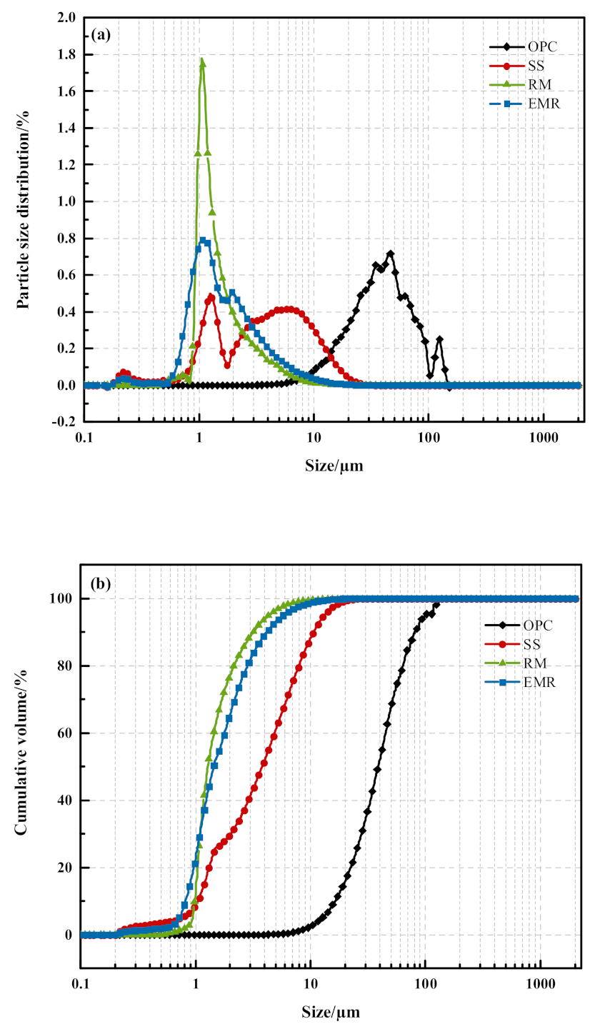
2.1. Raw Materials and Analysis

The cement used in this test is Conch P·O42.5 ordinary Portland cement (OPC). Table 1 shows the basic performance parameters of this study.
The SS is a converter steel slag produced by a steel company in Guangxi, with a density of 3.30 kg/m3 and a specific surface area of 667.5 m2/kg.
The RM is Bayer red mud discharged from an aluminum company in Guangxi, with a density of 3.02 kg/m3 and a specific surface area of 880.40 m2/kg.
The EMR is discharged from a company in Quanzhou, Guangxi, with a density of 2.59 kg/m3 and a specific surface area of 823.85 m2/kg. The chemical composition of the raw materials was analyzed by an X-ray fluorescence spectrometer (Table 2).
Figure 1 depicts the particle size distribution of the raw materials, where the particle size of OPC ranges from 5.3 to 164.8 μm, with an average size of 67.7 μm. The particle size of SS ranges from 0.2 to 29.5 μm, with an average size of 3.79 μm. The particle size of RM ranges from 0.5 to 9.4 μm, with an average size of 1.29 μm. The particle size of EMR ranges from 0.54 to 13.19 μm, with an average size of 1.46 μm. It can be judged that the D50 of the raw material particles are ranked from largest to smallest: OPC, SS, EMR, and RM, which is consistent with the experimental results of specific surface area.

2.2. Experimental Program

2.2.1. Specimens’ Preparation and Test Procedure

RM and EMR were ball-milled through 100-mesh sieves in this experiment. The RM was thermally activated at 700 °C for 2 h, and the EMR was mixed with 5% CaO. SS, RM, and EMR were prepared as SS–RM–EMR ternary composite mortar by replacing 30% of cement with different ratios, which was recorded as A0–A6. In total, 450 g of composite cementitious material, 1350 g of standard sand, and a water–cement ratio of 0.5 were used to configure the composite cementitious mortar. The specimens were studied for the impact of the ratios of SS, RM, and EMR on the performance of the composite cement mortar. The test ratios are shown in Table 3. The specimens were mixed and molded, demolded for 24 h, and then placed in a standard maintenance room at 22 °C and 90% humidity until the specified time.

2.2.2. Test Procedures

(1)
Density and specific surface area test: The density test of raw materials refers to the Chinese National Standard GB/T 208-2014 Cement Density Determination Method [12]. The specific surface area test refers to the Chinese National Standard GB/T 8074-2008 Cement-Specific Surface Area Determination Method: Burr’s Method [13].
(2)
Mechanical performance test: Referring to Chinese National Standard GB/T 17671-1999 Test Method For Cementitious Sand Strength (ISO Method) [14], the flexural strength and compressive strength of mortar specimens were tested at 3 d, 7 d, and 28 d.
(3)
Isothermal calorimetry: The hydration process of the slurry was monitored using isothermal calorimetry (TAM Air Thermometric, I-CAL4000/8000 made by Calmetrix Corporation, Boston, MA, USA, set at 25 °C). Manual stirring was performed, using a disposable spoon for 1 min to achieve the desired homogeneity. After stirring, the spoon was left in the sample cup to minimize the sample mass loss. Measurements were performed every minute for 72 h.
(4)
XRD analysis: The block samples of 3 d and 28 d were dried in a vacuum-drying oven at 40 ± 5 °C and then ground through 200 square mesh hole sieves with agate mortar powder. Next, a certain amount was taken with a medicine spoon, pressed into a mold, and tested using an X-ray diffractometer (PANalytical’s XPert Pro X-ray). The test diffraction angle was 5~80°, the dwell time was 0.5 s, and the scanning speed was 0.02°/min to identify the crystalline phase of the sample.
(5)
TG–DTG analysis: The 28 d lump samples were dried in a vacuum oven at 40 °C ± 5 °C and then ground through 200 square mesh hole sieves with agate mortar powder. Next, a certain amount was spooned into a crucible and tested using a thermogravimetric analyzer (Q 5000 IR) with an air atmosphere and a heating rate of 10 °C/min for the analysis of the hydration products of the samples.
(6)
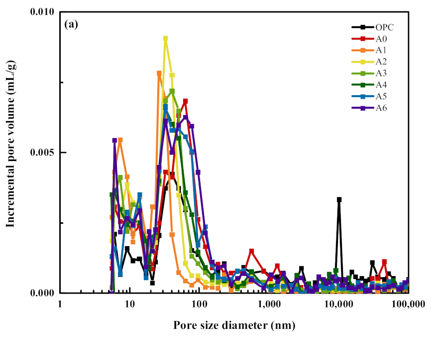
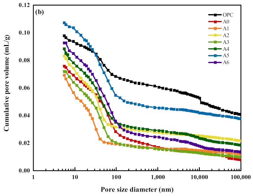
Pore structure analysis: After the block sample at 28 d was cut with a precision cutter about a size of 1 cm × 1 cm × 1 cm or so, the sample was dried in a vacuum drying oven at 40 °C ± 5 °C to obtain the final product. The pore structure of the mortar specimen was tested and analyzed by a high-performance automatic mercury pressure instrument.
(7)
Calculation method of activity index: Referring to Chinese National Standard GB/T 51003-2014 Technical Specifications For The Application Of Mineral Dopants, [15], the activity index of composite mortar was calculated according to the following formula, using pure cement group as the reference group.
A = R t R 0 × 100
where
  • A—activity index (%);
  • Rt—compressive strength of the examined sand at the corresponding age, in MPa;
  • R0—compressive strength of contrasting colluvium at the corresponding age, in MPa.

3. Results and Discussion

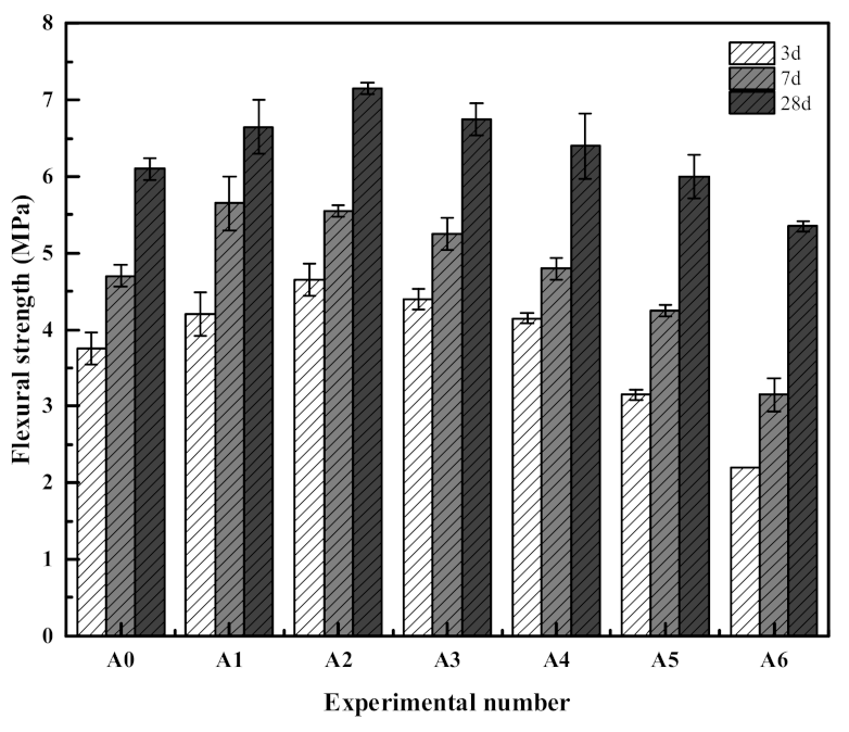
3.1. Mechanical Properties of Composite Mortar

Figure 2 depicts the flexural strengths of the composite mortar at 3 d, 7 d, and 28 d. The figure shows that compared with group A0, the flexural strength of composite mortar of groups A1–A6 at each age demonstrated a trend of first increasing and then decreasing. The flexural strengths at 3 d increased by 10.5%, 23.7%, 15.8%, 10.5%, −15.8%, and −42.1%, respectively. The flexural strengths at 28 d increased by 9.8%, 18.0%, 11.5%, 4.9%, −1.6%, and −11.48%, respectively. The highest flexural strengths were 4.7 MPa and 7.2 MPa for the composite mortar of group A2 at 3 d and 28 d, respectively.
Figure 3 shows the compressive strengths of the composite mortars at 3 d, 7 d, and 28 d. The compressive strength activity indices of the composite mortar for each group of A0–A6 at 3 d were 78.9%, 90.9%, 100.4%, 88.8%, 76.0%, 59.9%, and 40.5%, respectively. At 28 d, the compressive strength activity indices of the composite mortar for each group of A0–A6 were 59.9%, 72.1%, 75.1%, 74.0%, 66.4%, 58.3%, and 47.2%, respectively. Compared with group A0, the compressive strengths of composite mortars of groups A1–A6 exhibited a trend of first increasing and then decreasing at all time periods. The compressive strengths at 3 d increased by 15.2%, 27.2%, 12.6%, −3.7%, −24.1%, and −48.7%, respectively. The compressive strengths at 28 d increased by 20.3%, 25.5%, 23.6%, 10.9%, −2.7%, and −21.2%, wherein the highest compressive strengths were 24.3 MPa and 41.4 MPa for the composite mortar of group A2 at 3 d and 28 d, respectively.
The mechanical strengths of the composite mortars are lower than those of the OPC group because the active mineral components in SS, RM, and EMR are much lower than those in OPC. Their admixture dilutes the cementing ability of OPC, thus decreasing the mechanical properties. Compared with the A0 group, the flexural and compressive strengths demonstrated a trend of increasing and then decreasing with increasing EMR admixture (decreasing RM admixture), mainly because (i) compared with OPC and SS, the particle size of RM and EMR is smaller, and their admixture can play the role of filling the pores and improving the densities of the specimens; (ii) when compounded with suitable proportions of RM and EMR, the free alkali in RM and sulfate substances in EMR can stimulate the hydration activity of SS, thus reducing the negative effect of SS on the mechanical properties of mortar. Among them, the best mechanical properties of the composite mortar were obtained when15% of SS, 12% of RM, and 3% of EMR were mixed.

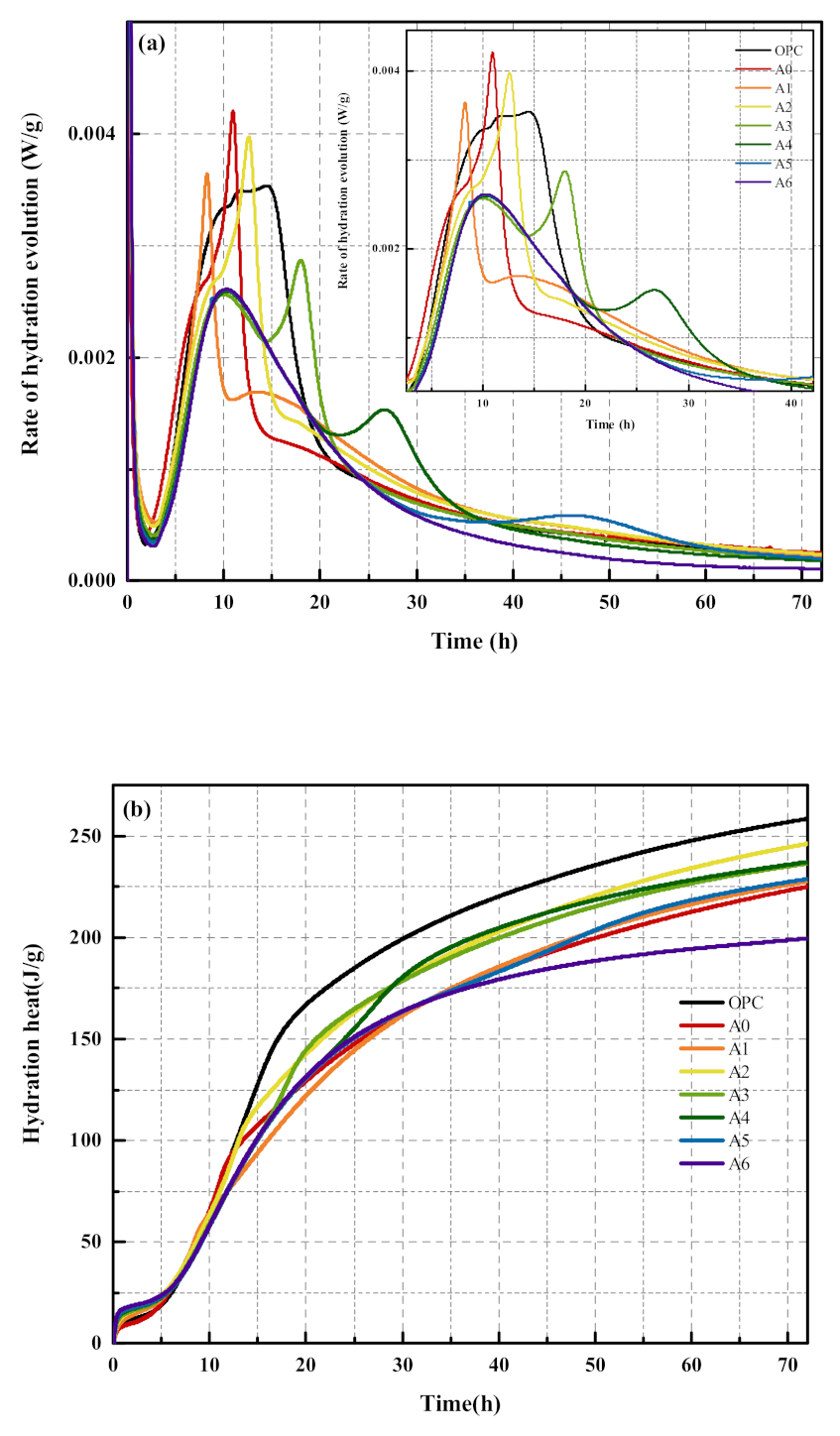
3.2. Analysis of Hydration Characteristics of Composite Mortar

The heat of hydration is an essential parameter for evaluating the hydration process of gelling materials, which can well reflect the dynamic process of slurry hydration [16]. Usually, the hydration reaction process of gelling materials is divided into five stages [17,18]: dissolution period, induction period, acceleration period, deceleration period, and stabilization period. Figure 4 shows the exothermic rates of hydration and accumulated exothermic heat of the composite net slurry for 72 h. The characteristic values of the hydration exothermic behavior are shown in Table 4. The exothermic rate diagram in Figure 4a shows that the first exothermic rate peak is formed rapidly after contact with water, which is caused by the exothermic dissolution of aluminates and sulfates in the cementitious material in contact with water [19]. Subsequently, the hydration reaction of the slurry enters the induction period, and small amounts of hydration products AFt and Ca(OH)2 are generated. Compared with the induction period of the OPC group, the induction period of the A0 group was prolonged, while the induction period of the A1–A6 group was shortened after the redoping of appropriate amounts of RM and EMR. In addition, during the acceleration phase, the peak of 3.32 × 10⁻³ mW/g was reached at 10.0 h for the OPC group and 4.20 × 10⁻³ mW/g at 10.9 h for the A0 group. In contrast, the induction period of the A1–A6 group was shortened after compounding with appropriate amounts of RM and EMR. With the increase of EMR doping, the appearance of the second exothermic rate peak was gradually delayed, and the peak height showed a trend of first increasing and then decreasing. Meanwhile, the third exothermic rate peak was gradually separated. The formation of the third exothermic rate peak was related to the recrystallization of AFt following sulfate depletion [20,21]. With the increase in EMR doping, the appearance of the third exothermic rate peak was gradually delayed and the peak height was steadily reduced. The cumulative exotherm plot in Figure 4b shows that the cumulative hydration exotherm of the composite system decreased to different degrees compared with the OPC system because of the dilution effect of SS, RM, and EMR doping. The hydration exotherm of the A0 group was significantly lower, with a cumulative hydration exotherm of 225.0 J/g at 72 h, which was 87.0% of that of the OPC group (258.5 J/g). After the blending of RM and EMR, with the increase of EMR, the cumulative heat release of hydration showed a trend of increasing first and then decreasing. It can be inferred that the incorporation of SS will inhibit the hydration reaction of the slurry, slow down the rate of hydration exotherm, and reduce the cumulative heat release of the slurry, while the compounding of RM and EMR in appropriate proportion can promote the hydration reaction of the slurry, accelerate the rate of hydration exotherm, and increase the cumulative heat release.
Figure 5 presents the XRD of the net slurry at 3 d and 28 d age. The figure shows that the main hydration products of the composite mortars of each group, except for the C–S–H gel, are mainly Ca(OH)2 and AFt and dicalcium silicate (C2S) and tricalcium silicate (C3S), which are not involved in the hydration reaction, with the appearance of a new material phase aluminous carbonate aluminate (Ca4Al2O6CO3·11H2O) at the age of 28 d There was no difference in the types of hydration products among the OPC, A0, and A1–A6 groups at each age, but only the peak intensities of the hydration product diffraction peaks were varied. Compared with the OPC group, the diffraction peaks of the hydration products Ca(OH)2 and AFt of the specimens in the A0 group were significantly weaker, which indicated that the incorporation of SS inhibited the hydration reaction of the slurry and led to the reduction of the hydration products. Compared with group A0, the diffraction peak intensity of Ca(OH)2 in group A1 was significantly lower, which was mainly because the admixture of RM promoted the hydration reaction of SS, accelerated the absorption of Ca2+ and reduced the content of Ca(OH)2. For the group A1–A6, in comparison, the diffraction peak of AFt was gradually enhanced with the increase of EMR admixture, which was mainly due to the higher content of SO42- in EMR, which could further react with the calcium aluminate gel generated by the hydration reaction to produce AFt [22].
Figure 6 shows the TG–DTG curves of composite net pulp at 28 d of age, and the mass loss rates are shown in Table 5. From the TG diagram, it can be learned that the total mass loss rate of each group of composite net pulp is in the order of A6 group > A4 group > A5 group > A3 group > A2 group > A1 group > A0 group from the largest to the smallest. Corresponding to the DTG diagram, it can be seen that four main decomposition peaks exist in each group of composite net pastes: the decomposition peaks existing before 60~300 °C correspond to the initial dehydration of C–S–H gels and the early thermal decomposition of AFt; the mass loss existing between 400~600 °C is mainly attributed to the thermal decomposition of Ca(OH)2; the mass loss existing between 600~750 °C is mainly caused by the thermal decomposition of calcite (CaCO3) produced by carbonization of the specimens during the hardening process [5,23]. From this, it can be judged that the content of hydration products Ca(OH)2, Aft, and C–S–H gel is significantly reduced in the specimens of group A0 compared to group OPC. Compared to the A0 group, the content of AFt and C–S–H gels gradually increased and the content of Ca(OH)2 gradually decreased in the A1–A6 group, which indicates that the compounding of suitable proportions of RM and EMR can promote the hydration reaction of the slurry, consume Ca(OH)2, and generate AFt and C–S–H gels that are more favorable to the development of mechanical properties, which is consistent with the XRD test results.
The pore structure distribution curves of the composite mortar at 28 d of age are shown in Figure 7. From the figure, it can be seen that the pore size distribution of the OPC and A0–A6 groups of specimens is relatively wide, and their most available pore sizes are 40.27 nm, 62.51 nm, 26.31 nm, 32.41 nm, 40.29 nm, 32.42 nm, 32.41 nm, and 32.42 nm, respectively. From the cumulative curve of the pore size distribution of the slurry, it can be seen that the approximate cumulative pore volume size is in the order of C5 group > OPC group > C6 group > C4 group > C2 group > A0 group > C3 group > C1 group. Wu [24] classified the mortar strength according to the degree of harm caused by the size of pores, which was mainly divided into four categories: harmless pores (<20 nm), less harmful pores (20–50 nm), harmful pores (50–200 nm), and multiharmful pores (>200 nm). The pore size distribution of composite mortar at 28 d age is shown in Table 6. It can be seen from the figure that the percentage of multiharmful pores > 200 nm in the specimens of the A0–A6 group decreased significantly and the percentage of nonharmful pores less than 20 nm increased significantly compared to the specimens of the OPC group. Comparing the pore structure distribution of the specimens in the A1–A6 group, it is found that with the increase of EMR doping (decrease of RM doping), the percentage of harmless and less harmful pores less than 50 nm gradually decreases, and the percentage of harmful and multiharmful pores more than 50 nm gradually increases, which indicates that when the EMR doping is too much, it is not conducive to the development of pore structure compactness.
Figure 8 shows the mechanism of action of SS–RM–EMR-based composite mortar. When 30% SS is mixed alone, the hydration reaction of the slurry will be inhibited due to the low activity of SS, while the negative effect of SS on the specimen can be effectively reduced after compounding the appropriate proportion of RM and EMR. On the one hand, the particle size of RM and EMR is relatively small, which can play the role of filling the pores; on the other hand, the free alkali in RM and sulfate substances in EMR can stimulate the hydration activity of SS, promote the vitreous body in SS, cause Si–O and Al–O bond breakage, release Ca2+ and silica–oxygen tetrahedra, and generate more AFt and C–S–H gel, thus improving the microstructure of mortar and improving the compactness of mortar. At the same time, it was found that the inert minerals in EMR had a great influence on the hydration reaction of the slurry and were not easily mixed in excessive amounts.

4. Conclusions

The conclusions regarding the mechanical properties and hydration behavior of SS–RM–EMR-based composite mortar are as follows:
  • Compared with the OPC group specimens, 30% SS alone will inhibit the hydration reaction of the slurry, resulting in the decrease of the mechanical properties of the mortar, while the compound mortar can improve the mechanical properties with the appropriate amount of RM and EMR. The 28 d flexural and compressive strengths of the composite mortar were the highest when 15% of SS, 12% of RM, and 3% of EMR were mixed, which were 7.2 MPa and 41.4 MPa, respectively. Compared with the test group with 30% SS alone, the 28 d flexural strength increased by 18.0% and the compressive strength increased by 25.5%.
  • Compared with the OPC group specimens, 30% SS alone reduced the hydration reaction rate and accumulated heat release of the slurry, while the compounding of appropriate amounts of RM and EMR can improve the hydration reaction rate and accumulated heat release of the slurry. The accumulated heat release of the slurry was 246.2 J/g when 15% of SS, 12% of RM, and 3% of EMR were mixed.
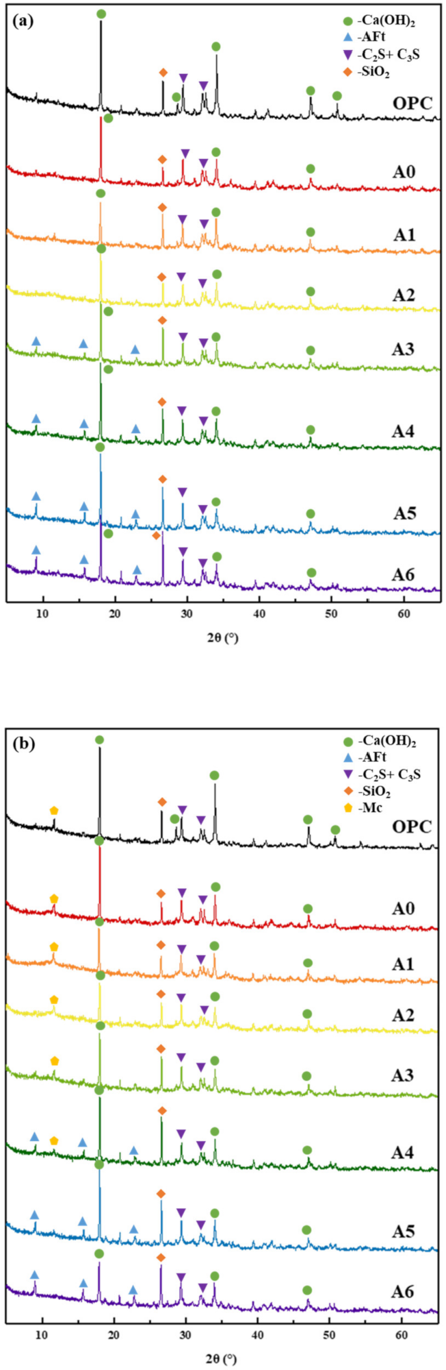
  • Compared with the OPC group specimens, 30% SS alone reduced the content of hydration products Ca(OH)2, Aft, and C–S–H gels, while compounding with appropriate amounts of RM and EMR can promote the slurry to produce more AFt and C–S–H gels, which are favorable for microstructure development and form a more dense hardened body structure. Compared with the specimens of 30% SS group, when 15% of SS, 12% of RM, and 3% of EMR are mixed, it can promote the generation of hydration products AFt and C–S–H gel and form more dense hardened body structure, which makes the overall decrease of harmless and harmful pores 26.35% and the overall increase of harmless and less harmful pores 43.57% in the composite mortar specimens.

Author Contributions

Conceptualization, L.Z.; methodology, L.Z.; investigation, L.Z., P.C. and C.H.; resources, L.Z.; data curation, L.Z.; writing—original draft preparation, L.Z.; writing—review and editing, L.Z, C.H. and L.Z; visualization, L.Z.; supervision, H.X. and Z.L. All authors have read and agreed to the published version of the manuscript.

Funding

The authors acknowledge the following institutions for providing facilities and the financial support: Guangxi Science and Technology Program Project (no. Guike AD21220052 and Guike AD22035126), National Natural Science Foundation of China Project (NO. 52062009), Guangxi University Young and Middle-aged Teachers’ Scientific Research Ability Improvement Project (nos. 2022KY0242 and 2021KY0262).

Institutional Review Board Statement

Not applicable.

Informed Consent Statement

Not applicable.

Data Availability Statement

Not applicable.

Conflicts of Interest

The authors declare that they have no conflict of interest.

References

  1. Statistical Bureau of the People‘s Republic of China. China Statistical Yearbook; China Statistics Bureau Press: Beijing, China, 2021. [Google Scholar]
  2. Pang, L.; Liao, S.C.; Wang, D.Q.; An, M.Z. Influence of steel slag fineness on the hydration of cement-steel slag composite pastes. J. Build. Eng. 2022, 57, 104866. [Google Scholar] [CrossRef]
  3. Zhuang, S.Y.; Wang, Q. Inhibition mechanisms of steel slag on the early-age hydration of cement. Cem. Concr. Res. 2021, 140, 106283. [Google Scholar] [CrossRef]
  4. Liu, Y.; Zhang, Z.Q.; Hou, G.H.; Yan, P.Y. Preparation of sustainable and green cement-based composite binders with high-volume steel slag powder and ultrafine blast furnace slag powder. J. Clean. Prod. 2021, 289, 125133. [Google Scholar] [CrossRef]
  5. Hao, X.S.; Liu, X.M.; Zhang, Z.Q.; Zhang, W.; Lu, Y.; Wang, Y.G.; Yang, T.Y. In-depth insight into the cementitious synergistic effect of steel slag and red mud on the properties of composite cementitious materials. J. Build. Eng. 2022, 52, 104449. [Google Scholar] [CrossRef]
  6. Yi, L.S.; Wen, J. Research status and progress of steel slag activity excitation technology. Silic. Bull. 2013, 32, 2057–2062. [Google Scholar]
  7. Xu, Y.T.; Liu, X.M.; Zhang, Y.L.; Tang, B.W.; Mukiza, E. Investigation on sulfate activation of electrolytic manganese residue on early activity of blast furnace slag in cement-based cementitious material. Constr. Build. Mater. 2019, 229, 116831. [Google Scholar] [CrossRef]
  8. Zhang, W.; Hao, X.S.; Wei, C.; Zeng, Q.S.; Ma, S.L.; Liu, X.M.; Zhang, Z.Q.; Webeck, E. Synergistic enhancement of converter steelmaking slag, blast furnace slag, Bayer red mud in cementitious materials: Strength, phase composition, and microstructure. J. Build. Eng. 2022, 60, 105177. [Google Scholar] [CrossRef]
  9. Wang, Z.W.; Chen, P.; Zhou, H.Y.; Zhao, Y.R.; Liu, R.J.; Wei, J.X. Study on the heat of hydration of steel slag electrolytic manganese residue red mud composite cementitious material. Nonmet. Min. 2019, 42, 88–90. [Google Scholar]
  10. Palankar, N.; Ravi Shankar, A.U.; Mithun, B.M. Investigations on Alkali-Activated Slag/Fly Ash Concrete with steel slag coarse aggregate for pavement structures. Int. J. Pavement Eng. 2017, 18, 500–512. [Google Scholar] [CrossRef]
  11. Guo, X.; Shi, H.; Wu, K. Effects of Steel Slag Powder on Workability and Durability of Concrete. J. Wuhan Univ. Technol. 2014, 29, 733–739. [Google Scholar] [CrossRef]
  12. GB/T 208-2014; Cement Density Determination Method. General Administration of Quality Supervision, Inspection and Quarantine: Beijing, China, 2014; pp. 1–3.
  13. GB/T 8074-2008; Cement-Specific Surface Area Determination Method: Burr’s Method. General Administration of Quality Supervision, Inspection and Quarantine: Beijing, China, 2008; pp. 1–4.
  14. GB/T 17671-1999; Test Method for Cementitious Sand Strength (ISO Method). The State Bureau of Quality and Technical Supervision: Beijing, China, 1999; p. 9.
  15. GB/T 51003-2014; Technical Specifications for the Application of Mineral Dopants. General Administration of Quality Supervision, Inspection and Quarantine: Beijing, China, 2014; pp. 24–27.
  16. Jennings, H.M.; Johnson, S.K. Simulation of microstructure development during the hydration of a cement compound. J. Am. Ceram. Soc. 1986, 69, 790–795. [Google Scholar] [CrossRef]
  17. Wu, W.J. Study on the Hydration Process and Performance of Steel Slag-Cement Composite Cementitious Materials. Master’s Thesis, Beijing University of Chemical Technology, Beijing, China, 2016. [Google Scholar]
  18. Zhang, S.F.; Niu, D.T. Hydration and mechanical properties of cement-steel slag system incorporating different activators. Constr. Build. Mater. 2023, 363, 129981. [Google Scholar] [CrossRef]
  19. Zhou, X.; Du, L.; Li, F.Y.; Zhou, S.F.; Shao, S.; Zhang, X.; Peng, J. Study on the effect of clinker fineness of silicate cement on hydration behavior and strength of phosphorus building gypsum. New Build. Mater. 2022, 49, 129–132. [Google Scholar]
  20. Huang, S.Y.; Huo, B.B.; Chen, C.; Zhang, Y.M. Effect of metakaolin on the hydration of steel slag cement-based composite systems under steaming conditions. Mater. Guide 2022, 36, 69–74. [Google Scholar]
  21. Boháč, M.; Palou, M.; Novotný, R.; Másilko, J.; Všianský, D.; Staněk, T. Investigation on early hydration of ternary Portland cement-blast-furnace slag metakaolin blends. Constr. Build. Mater. 2014, 46, 333–341. [Google Scholar] [CrossRef]
  22. Chen, P.; Hu, C.; Xiang, W.H.; Tian, Y.; Liu, R.J. Research on the structure and properties of steel slag-manganese slag composite cementitious materials. J. Wuhan Univ. Technol. 2019, 41, 1–5. [Google Scholar]
  23. Zhang, N.; Li, H.X.; Peng, D.D.; Liu, X.M. Properties evaluation of silica-alumina based concrete: Durability and environmental friendly performance. Constr. Build. Mater. 2016, 115, 105–113. [Google Scholar] [CrossRef]
  24. Wu, C.W. Reflections on the science and technology of concrete. Concr. Cem. Prod. 1988, 6, 4–6. [Google Scholar]
Figure 1. Particle size distribution of raw material particles: (a) particle size distribution; (b) cumulative distribution.
Applsci 13 05913 g001
Figure 2. The flexural strength of composite mortar.
Applsci 13 05913 g002
Figure 3. The compressive strength of composite mortar.
Applsci 13 05913 g003
Figure 4. Hydration exothermic curve of composite mortar: (a) hydration heat evolution rate; (b) cumulative hydration heat.
Applsci 13 05913 g004
Figure 5. XRD pattern of composite net pulp: (a) 3 d; (b) 28 d.
Applsci 13 05913 g005
Figure 6. TG–DTG curve of composite net slurry: (a) TG curve; (b) DTG curve.
Applsci 13 05913 g006
Figure 7. Composite mortar distribution of the pore structure: (a) pore size distribution; (b) cumulative distribution.
Applsci 13 05913 g007aApplsci 13 05913 g007b
Figure 8. The principal diagram of the experiment.
Applsci 13 05913 g008
Table 1. The basic properties of the concrete parameters.
Density (kg/m3)Specific Surface Area (m2/kg)Flexural Strength
(MPa)
Compressive Strength
(MPa)
3 d7 d28 d3 d7 d28 d
OPC3.15356.505.26.47.224.235.655.1
Table 2. The chemical composition of the raw materials (wt%).
Fe2O3Al2O3TiO2SiO2CaOMgONa2OK2OMnOSO3Other
OPC3.715.640.3024.7660.250.880.160.700.323.28
SS24.155.660.5726.9529.675.330.090.085.392.11
RM30.5820.397.8013.4915.820.339.150.190.142.11
EMR5.457.430.5528.2118.733.660.042.434.1828.520.80
Table 3. Experimental proportioning (wt%).
SampleOPCSSRMEMRSand–Binder RatioWater–Binder Ratio
A07030001:30.5
A17015150
A27015123
A3701596
A4701569
A57015312
A67015015
Table 4. Compound mortar exothermic peak occurrence time and its 72 h total exothermic heat.
SampleSecond Exothermic Peak/hThird Exothermic Peak/h72 h Total Heat Release /J·g−1
OPC10.0258.5
A010.9225.0
A18.2227.7
A29.2246.2
A39.517.9236.6
A410.026.2237.3
A510.146.1228.9
A69.9199.5
Table 5. Composite mortar mass loss rate at 28 days (wt%).
SampleMass Loss/%
60~300 °C400~600 °C600~750 °C
OPC9.318.029.18
A021.8115.8827.97
A135.4830.453.28
A226.2227.894.27
A325.2632.4510.94
A424.5823.0210.10
A513.4519.8712.82
A619.7323.2919.31
Table 6. Composite mortar distribution of the pore structure.
SamplePorosity/%Pore Size Distribution/%
<20 nm20~50 nm50~200 nm>200 nm
OPC18.259.318.029.1873.49
A015.9021.8115.8827.9734.34
A114.1335.4830.453.2830.79
A216.8026.2227.894.2741.62
A314.9825.2632.4510.9431.35
A418.2124.5823.0210.1042.30
A521.1313.4519.8712.8253.86
A619.1619.7323.2919.3137.67
Disclaimer/Publisher’s Note: The statements, opinions and data contained in all publications are solely those of the individual author(s) and contributor(s) and not of MDPI and/or the editor(s). MDPI and/or the editor(s) disclaim responsibility for any injury to people or property resulting from any ideas, methods, instructions or products referred to in the content.

