1. Introduction
Every year, millions of people are affected by disasters. In 2021 alone, the Emergency Event Database (EM-DAT) recorded 432 disastrous events related to natural hazards worldwide. Overall, these accounted for 10,492 deaths, affected 101.8 million people, and caused approximately 252.1 billion USD of economic losses [
1]. To alleviate the impact of disasters, governments invest in prevention and maintain relief bodies. Prevention is achieved by legislation, such as earthquake codes, and public works, such as tsunami walls or firebreak zones. Disaster relief can include capabilities for damage assessment, coordination, specialized personnel at Urban Search And Rescue (USAR), civil protection, and even armed forces. Despite these efforts to reduce the impact of disasters, their scale and ferocity can leave entire countries in disarray. Countries experiencing such events receive additional assistance from the international community through Intergovernmental Organizations (IGOs) and Non-Government Organizations (NGOs). NGOs provide not only material support but also assistance through volunteer USAR teams formed by citizens motivated into action to assist their fellow citizens in times of need.
Just like their government-sponsored counterparts, volunteer USAR teams require equipment to cope with the challenges presented during relief missions. The equipment used ranges from ropes to listening devices (vibration or seismic detectors, also known as geophones), search cameras to view victims, radar movement detectors, and even K9 dogs, drones, or robots. In addition, there is the need for communication and IT infrastructure to support other tools or relay information to a USAR Coordination Cell (UCC) [
2] where information is gathered and the overall effort of rescue teams is coordinated. In the past, the provision of voice communication over VHF/UHF radios was sufficient, but today there is the need to transfer images, videos, or access cloud services. Moreover, it is not uncommon for command and control software to be utilized to provide a common operational picture. For this to work, at least the team leaders and, ideally, the various assets deployed in the field must be able to exchange information with the UCC. Consequently, there is the need for connectivity which can be divided into two categories: local wireless connectivity and backhaul connectivity towards the UCC and the internet.
Local wireless connectivity is needed both at medium (<150 m) and at long ranges (<1000 m) to support different types of devices. Medium-range wireless communication targets devices such as tablets, cell phones, or inter-component communication for a single tool, such as data transmission from a drone tethering station to a video server. Long-range communication supports wearable devices used by the First Responders to track them or monitor their vitals with the aim of protecting their well-being and safety. Backhaul connectivity towards the UCC and the internet is used to transfer the information gathered by the local wireless network to the UCC or provide access to remote services, on which an ever-growing percentage of devices rely. Besides the need to provide two types of connectivity, a field communication system that can be used by volunteer USAR teams cannot use Commercial Off The Self (COTS) products that operate in licensed parts of the spectrum. Instead, hardware that can be used freely by any individual has to be selected. Additionally, a communication solution destined to be used in times of emergency should be self-sufficient. Reliance on civil infrastructure, such as the power grid or cellular networks, has to be avoided. The overall size and weight of the any proposed solution should permit easy transfer and deployment. A more detailed analysis of the user requirements of such a system can be found in our previous work in [
3].
When it comes to emergency communications, the most prevalent type of solution described in the literature are Mobile Ad-hoc Networks (MANETs) [
4,
5,
6,
7,
8], due to their ability to bridge long distances through retransmission by intermediate nodes, their self-healing capability (selecting new routes when a node goes offline), and their compatibility with low-cost hardware. However, the presented systems in the literature remain rather abstract. There is no explanation or guidelines for equipment selection, how to power it, the offered data rate, or what is the actual achieved communication range. In addition, while in theory, they are able to provide communication over large areas and are self-healing, the real-world realization of those traits requires a large number of deployed nodes with adequate spatial dispersion, which is not realistic. Moreover, the proposed MANET networks are accessed by the end devices through a single technology, usually WiFi, a practice that is not compatible with the diverse characteristics and requirements of the equipment used by First Responders, as described previously.
Another type of communication system gaining popularity for use in emergency and disaster scenarios is LoRaWAN due to its capability to form private networks with standalone concentrators, offering long-range and low power operation. The primary-use case of this kind of system for disaster response is message exchange either between civilians and the authorities to request assistance or civilians themselves to inform their families about their status [
9,
10,
11]. LoraWAN is a promising solution, but due to its limited bandwidth, it can not provide a solution on its own, but can rather function as a complementary one.
With this article, we present a different approach to providing a communication solution for volunteer USAR teams in cases of emergencies. We propose a system that combines the latest WiFi standard, 802.11ax, with a LoRaWAN network for local wireless access and a multitude of backhaul interfaces for internet access and communication with the UCC. The combination of 802.11ax and LoRaWAN addresses the need for medium and long-range wireless connectivity, offering a solution that covers both devices that require considerable bandwidth or low power operation and long-range. For the access to the internet and the UCC, an approach that provides resilience through redundancy has been followed. Since, after a disaster, the civilian communication infrastructure may be unavailable either because it has been damaged or overloaded, our system exploits 4G, xDSL, a Satellite Module, and a Point to Point link for remote access. The Point to Point link can either be used to establish connection to the UCC or a remote location with internet access and the xDSL interface to connect the system with wired infrastructure or some other system deployed in the area, for example, a MANET backbone. The aforementioned interfaces are transparently handled by our system, with traffic being routed based on a predefined interface priority scheme with an automatic switch to a different interface in case of failure. This functionality is provided by a system with the necessary Technology Readiness Level (TRL) to be deployed in the field and meet requirements for ruggedization, fast deployment, and easy transfer. The system has been evaluated within the small and large-scale field tests of the INGENIOUS project [
12], and the results are presented here.
Contributions. The design and implementation of a novel communication system for volunteer USAR teams, combining 802.11ax WiFi and LoRaWAN, routes the traffic through multiple backhaul interfaces to achieve resilience through redundancy. The wireless coverage of the system is experimentally evaluated and the real-world performance improvement offered by the new 802.11ax Wifi standard is determined in practice through a measurement campaign.
The rest of the paper is organized as follows. In
Section 2, the hardware components of the proposed system are presented. Next, in
Section 3, the system’s description is concluded with the presentation of the software part.
Section 4 and
Section 5 document the measurement campaign and the comparison of the 802.11ax WiFi standard with its predecessors.
Section 6 includes the field evaluation of the system, and finally, in
Section 7, we conclude our article.
2. Hardware Components
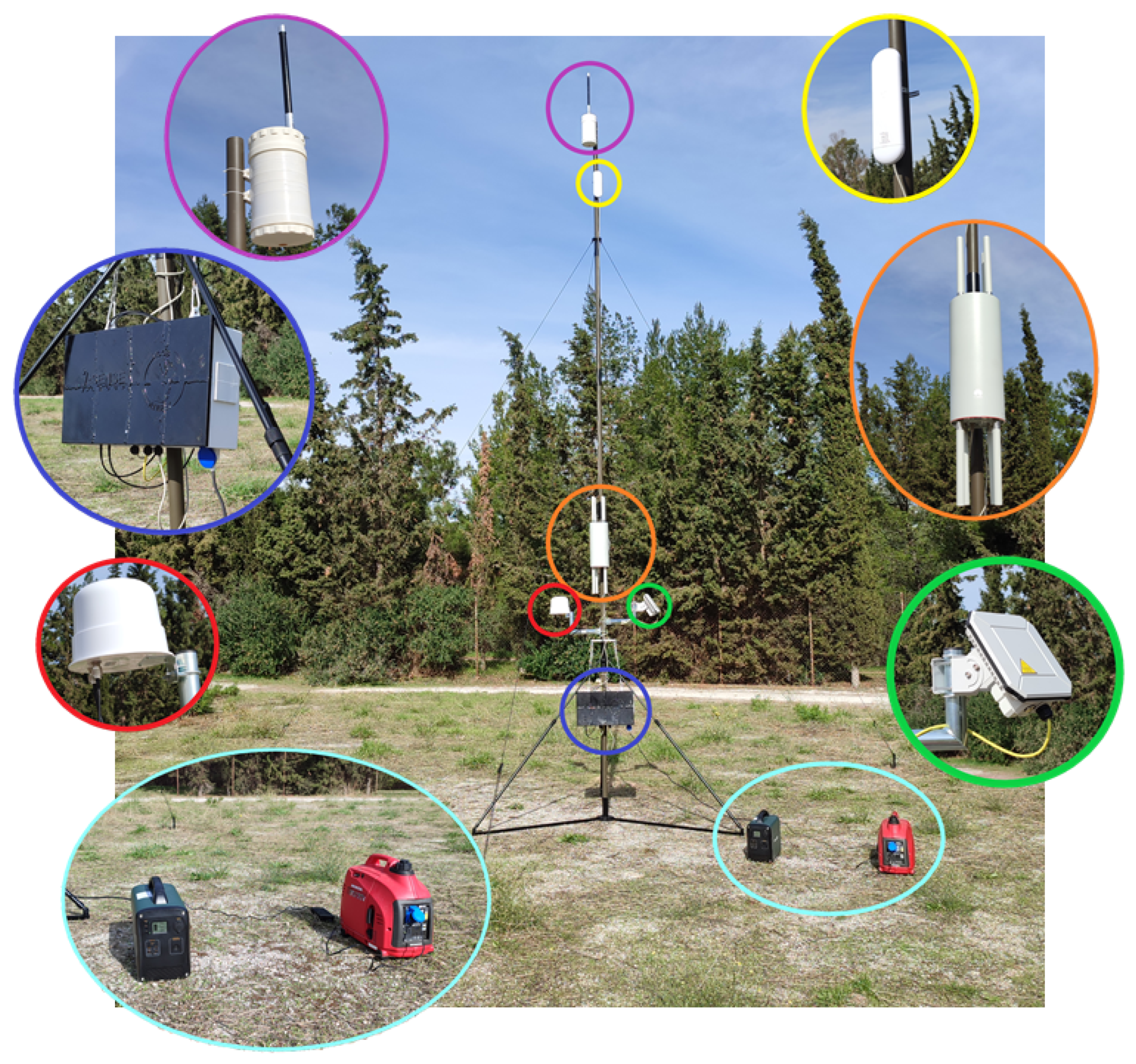
Considering the system requirements presented in the introduction, the necessary hardware equipment has been selected and assembled in a field deployable solution depicted in
Figure 1. The components comprising the solution are listed here and are, with the exception of the antenna mast, color-coded for easy recognition:
LoRaWAN concentrator (purple);
Point to Point radio (yellow);
Satellite Communication terminal (green);
Power supply (generator + portable battery power station) (cyan);
4G antenna (red);
WiFi 6 AP (orange);
Central Communication Node (blue);
Antenna mast.
In what follows, we describe each component in detail along with the rationale behind our choice.
Antenna mast. We begin the presentation of the proposed communications solution for the First Responders (FRs) with the antenna mast. It might not be the most high-tech component included in our kit but it is a rather important one. A significant factor affecting the covered area of a wireless communication system is antenna height. Its effect is discussed in the ITU-R P.1411 recommendation [
13], where a relation between antenna height and communication range is established with the introduction of a communication distance break point, further from which the signal attenuation increases rapidly. Additionally, the antenna clearance of the surrounding environment determines the particular path loss model that best predicts the communication range. Models that are applicable to antenna heights greater than those of the surrounding obstacles are more forgiving in terms of attenuation. However, higher is not always better since a communication range greater than necessary leads to susceptibility for interference.
It becomes evident that providing the means to alter the antenna height is essential for a successful system deployment. For this to be accomplished, a foldable antenna mast comprised of multiple identical sections is selected, which provides the ability to adjust the antenna height, giving the opportunity to adapt to the topological situation encountered on the ground by dynamically selecting the correct height. The main requirements are that the mast should be rated for a weight of up to 6 kg at the top, can be erected to a height of up to 6 m, is deployed without much effort, and occupies little space when packaged. Furthermore, it should provide the means to mount the rest of the equipment on its base. We use the ST-R [
14] antenna mast from Trival Antene. It is a foldable antenna mast with sections made out of glass-reinforced polyester material and an overall weight of
kg, making it suitable for single person carry. Its three-leg stay is designed for very quick elevation of the mast even on inclined ground and is accompanied by a guying set which can be used to fix the antenna mast firmly in place.
Satellite communication terminal. Satellite communication has traditionally been a high-cost service with limited bandwidth and a transmission latency in the range of seconds due to signal delay caused by the long round trip from the earth to the satellite. However, it has global coverage and high availability and is thus one of the most resilient communication methods, making it a necessity for a communications solution targeting first responders. The Cobham Explorer 540 satellite terminal [
15] is included here. It is a small (20 cm × 20 cm) and lightweight (
kg) rugged IP66 design, offers up to 464 kbps of data rate, and can be installed in a timely manner due to its audio-assisted satellite alignment functionality.
LoRaWAN concentrator. On the top of the antenna mast, in the purple circle, is a LoRaWAN concentrator. LoRaWAN is a Low Power, Wide Area (LPWA) networking protocol usually associated with the Internet of Things (IoT) devices. We have included it in our solution to provide for a reliable communication method in hard-to-reach areas so as to ensure a minimum communication bandwidth for distress signals and the output of vital sign sensors. The concentrator is a custom-built one, based on the Raspberry Pi 3 Model B+ [
16] Single Board Computer (SBC) and the RAK2287 [
17] LoRa modem. The node can be powered using either Power over Ethernet (PoE) or by its own rechargeable battery, which provides for more than 2 days of continuous operation. We have designed and 3D printed an enclosure to accommodate the aforementioned parts in a single component, depicted in
Figure 2. The SBC enables us to use an open-source software LoRaWAN stack, ChirpStack, and set it up locally. Consequently, the concentrator does not need internet access to communicate with a remote LoRaWAN network server for its operation and is self-sufficient.
Mobile broadband modem. Broadband cellular networking is the most ubiquitous form of wireless internet connectivity used in our everyday lives. Despite this, in cases of emergencies, it has been noticed that there can be low availability or interruptions of service due to damage or overloading of the internet service provider’s infrastructure. Still, it is a cost-effective and worldwide available service, and our system should be able to take advantage of it whenever possible. Consequently, our system incorporates a 4G router, the Teltonika RUT950 [
18]. It is a high-performance cellular router featuring dual SIM with auto-switch capability in cases of weak signal or data connection failure, designed as a Main/Backup internet source. The operation of the 4G router is augmented by an external 4G LTE
Multiple Input, Multiple Output (MIMO) omnidirectional antenna with a gain of 12 dBi. The relaxed space restrictions and the know orientation of the antenna permit the use of an antenna with more gain than the ones installed in cellphones leading to better signal-to-noise ratios and thus, higher data transmission rates. The modem itself is installed inside the central communication node.
Point to Point link. Point to Point microwave links enable the connection of fixed locations separated by large distances while offering low latency and high bandwidth. The inclusion of a Point-to-Point link adds to the versatility and resilience of our solution because it can be used to address different needs that may arise during a USAR mission. Its inclusion provides an extra WAN interface to exploit the availability of internet connectivity at some remote but still reachable location, enables the provision of connectivity at a secondary location not covered by the WLAN (such as a UAV ground control station), or the connection of additional APs to the base station via a wireless backbone. The latter provides the means to extend the system on the fly and interconnect distant areas of operations. The long-range and high data rate communication capabilities can be mainly attributed to the directive antennas utilized at both ends. The greater the antenna gain, the higher the effective radiated power and, as a result, the distance that can be bridged for a given bandwidth. Antennas are passive elements that create gain by focusing signal radiation at a particular area, meaning there is an inverse relation between gain and antenna beamwidth. Narrow beamwidths lead to prolonged and, at times, not successful antenna alignment procedures, and consequently, a compromise must be made between antenna gain and ease of installation. The airMAX NanoStation AC 5 GHz radio [
19] with a 3 dB beamwidth of 45 degrees and gain of 16 dBi, has been chosen. It is a ready-to-use solution for Point-to-Point links and is able to bridge considerable distances if adequate ground clearance is provided.
Power Supply Module. The system requires a single 230 V/50 Hz power supply that is used to generate the required voltages for the rest of the components. In order to provide for continuous operations for extended periods of time, a combination of gasoline-powered and battery-powered generators has been chosen for the two power sources to be used, connected in the series as a hybrid solution. The gasoline-powered generator is aimed at providing power most of the time, while the battery-powered generator acts as a backup to allow for the refueling of the main generator and to ensure system operation even in cases of failure of the primary power source. The gasoline-powered generator is sized for powering the equipment and charging the portable battery power station at the same time. We use the Honda EU10i Generator [
20], which can deliver up to 1000 W and at a weight of 13 kg, can be managed by a single person. It achieves an 8-h continuous operation time without refueling at one-fourth of the maximum load. The portable battery power station included in the deployable equipment is the PowerOak PS7 [
21], a compact solution for portable power, which offers 1000 Wh at 15.6 kg of weight. It has a nominal power output of 600 W and provides outputs of various types and voltages. There is a 12 V DC output, USB-C and USB-A outputs, and two 230 V AC outputs, covering not only the needs of the field communication system but also allowing the FRs to charge other devices or equipment if needed.
802.11ax Access Point. An 802.11ax [
22] capable Access Point (AP) is used to set up the WLAN network. The 802.11ax standard, also known as WiFi 6, is an incremental improvement over the previous generations of WiFi networks and delivers several key improvements that are applicable to the INGENIOUS use case, namely:
A more efficient medium access control method, orthogonal frequency division multiple access, that in contrast to the carrier-sense multiple access with collision avoidance, is able to mitigate collisions by allocating parts of the spectrum to the various station devices and thus move the network from a contention to schedule based service. The proposed communication system must support multiple station devices with diverse bandwidth needs, making simultaneous use of the wireless channel and thus compete for air time. OFDMA is better suited to manage such use cases, resulting in a network with a higher throughput and lower access latency.
Longer symbol duration and guard interval. Multipath propagation over long distances can cause intersymbol interference, a type of self-interference ominous in outdoor wireless communications caused by delayed symbols arriving at the receiver. Guard intervals are used to ensure that distinct transmissions do not interfere with one another, and 802.11ax provides the option for up to four times longer guard intervals in comparison to the previous standards, at
. By increasing the guard interval and the symbol duration, the percentage of airtime used for data transmission remains unchanged, and thus the communication distance can be increased without sacrificing transmission speed [
23].
802.11ac allowed for multi-user MIMO transmissions only from the AP towards the stations (DL MU-MIMO). This allowed for the increase of the total downlink throughput and was advantageous in usage scenarios when the stations mostly downloaded data. In INGENIOUS, the situation is different due to the need to upload video streams and sensor data for remote processing and the creation of a common operational picture. WiFi 6 expands the MU-MIMO capability to uplink transmissions, delivering a communication technology better equipped to handle networks where uplink traffic dominates [
24].
802.11ax adopts the power-saving technique introduced in IEEE 802.11ah, called Target Wake Time (TWT). This allows an access point to define a specific time or set of times for devices to access the wireless network resulting in increased sleep time and therefore, reduced power consumption. Moreover, spectral efficiency is optimized by reducing contention and overlap between users [
25].
The 802.11ax standard describes several new and exciting features, but a lot is left to the devices implementing it. The number of spatial streams supported is product related, and so is the support for simultaneous dual-band operation (at
and 5 GHz) and station band steering, to name a few. The AirEngine 8760R-X1E [
26], a WiFi 6 compliant outdoor (IP68 certified) AP, is included in our filed deployable communications system. It has an 8 × 8 multi-user MIMO capability thanks to its eight external removable omnidirectional antennas and utilizes three standalone physical radios that allow multiband operation and station segmentation over different wireless networks. Complementary to the radio capabilities are the device’s software features. An extensive Management Information Base (MIB) is provided that makes accessible a multitude of information per station device and permits the configuration of wireless multimedia extension parameters of the stations, which can be leveraged to provide programmable Quality of Service over the wireless network.
Central communication node. The INGENIOUS communications toolkit includes multiple devices offering various types of communication service. In order to have an integrated and easy-to-use system, those components must be interconnected and combined into a single solution. The central communication node provides the necessary power to the rest of the equipment through PoE capable ports and handles the routing of the network traffic. As a result, a single cable connection per component is needed, both for power and data, while the creation of a custom enclosure that includes both the PoE injectors and the routing device adds to the ease of use of the system. The custom designed and 3D printed enclosure can be seen in
Figure 3a.
Figure 3b presents the internals of the central communication node. Moving from left to right, there is a fan, the 4G modem, the fanless industrial pc used for the routing, three PoE injectors, and another fan.
The WLAN is expected to produce large volumes of network traffic. Therefore, the device handling the routing must have the necessary computational power for the task. Running open-source software is a must to allow for customization, integration of all the different hardware and software components, and avoidance of vendor lock. Our communication system has four WAN interfaces and one WLAN interface, leading to the need for at least five Ethernet ports to accommodate the aforementioned interfaces. To meet those specifications, the Protecli Vault 6 Port [
27] is used. It is powered by an Intel i5 CPU, can utilize up to 64 GB of RAM, provides six Ethernet ports, and can host the Linux operating system. The software running inside manages the network and decides how to route traffic based on the available interfaces.
3. System & Network Traffic Monitoring
Communications are critical for search and rescue operations and consequently, the operational status of the equipment and the network needs to be monitored. The system features monitoring and alerting services to inform its operator about the current status of the equipment and produce Common Alerting Protocol (CAP v1.2)-compliant messages when a device is connected/disconnected from the network or has low signal strength. The latter aids in integrating the system with other tools, such as command and control software, commonly used to manage search and rescue operations. The aforementioned services are executed locally, in the central communication node, and the relevant user interfaces are web based, meaning that they can be accessed without any prior need for software installation or configuration.
The monitoring of the equipment is based on the Nagios Core [
28], an open source monitoring and alerting engine, and the Simple Network Management Protocol (SNMP). Through SNMP, Nagios Core is able to retrieve information from the components comprising the system with respect to their status and component specific parameters. Owing to the use of SNMP, which enjoys widespread support, this scheme is both highly modular and widely applicable. Any device hosting an SNMP agent can be integrated with the rest of the system.
Figure 4a presents the User Interface (UI) of the monitoring service. The connectivity of every component is regularly checked and reported (PING field) and various information specific to each component, such asthe number of wifi clients or 4G connection status, are reported. In part (b) of
Figure 4, a graph of the network traffic through selected interfaces can be seen. The full green area represents the download traffic of the interface while the blue line represents the upload. Through it, the operator of the system can receive information about the usage of various resources such as the 4G connection, or the Point to Point link and identify bottlenecks or abnormal behavior.
4. Measurement Campaign & Equipment
In order to validate the suitability of our solution for providing wireless connectivity at a local area level, we planned and executed a measurement campaign of the received signal strength and data rate for the WiFi and LoRaWAN networks. To this aim, we developed a portable logging system presented in
Figure 5a. It includes two different radios, the RFM95CW [
29] LoRa transceiver module and the Intel Wi-Fi 6 AX200 adapter [
30], integrated into a single system by the OnLogic CL200G-10-RS [
31] single board computer (SBC). The Wi-Fi adapter is placed at the waist at a height of 1 m from the ground and the LoRa module 20 cm lower at 0.8 m from the ground. These positions are indicative of the equipment attached to the belt of the FR’s uniform, while the height of the Wi-Fi adapter from the ground is close to the height that the devices placed on top of tables would have been, covering both cases. Additionally, there is a touch screen for initiating the logging process and presenting the results so far to give the operator a notion of the area covered, as can be seen in
Figure 5b. The position of each signal measurement is captured by an RTK GNSS receiver installed on top of the helmet worn by the operator.
The location selected for the measurement campaign can be seen in
Figure 6. This is a dirt football field surrounded by trees within the university campus. At a greater distance, there are several buildings. This open space, which resembles a park, is a good example of a location that would have been selected by the FRs to deploy their equipment, local command center, and logistic infrastructure.
For the Wifi, we have selected a configuration optimized for a maximum communication range. This means selecting the longer possible guard interval for every standard to safeguard against intersymbol interference and a lower bandwidth to reduce the noise power ensuring the highest possible signal-to-noise ratio (SNR). On the other hand, LoRaWAN’s parameters favor transmission speed and, as a result, data volume over range. For both WiFi and LoRaWAN, the samples taken relate to actual data transfer and not just RSSI or speed measurement. Wireless adapters calculate new channel-related metrics when they receive new traffic, making data exchange between the station/node and AP/concentrator a necessity. Due to this, sample points mark locations where communication is possible and can provide a rough estimation of the validated coverage area.
Table 1 summarizes the parameters used by every technology and the number of samples taken during the measurement campaign.
5. Measurements Processing & Results
The measurement campaign corresponds to the sampling of a spatial function. Moving from space discrete samples to a continuous surface is necessary in order to develop a Radio Environment Map (REM) and extract area-related metrics, such as the coverage area, or to visualize the transmission speed over the area of interest. This process, the estimation of new data points based on the range of a discrete set of known data points, is called interpolation. References [
32,
33,
34,
35,
36,
37] outline some of the most common methods used to perform spatial interpolation for the purpose of developing a REM and provide information about the performance of the various techniques and their applicability. In this work, we select a well-known and broadly accepted spatial interpolation method, Ordinary Kriging with detrending [
38,
39]. Despite being one of the most competent interpolation methods for the purpose of building REMs, we found the performance of other methods such as Radial Base Functions (RBFs) or Inverse Distance Weighting (IDW) to be similar due to the dense sampling that was carried out in this measurement campaign.
Ordinary Kriging estimates the value
of a wide sense stationary random field at an unsampled location
x through the use of a linear combination of known sample values.
The selection of the coefficients is based on spatial dependence. Samples closer to the unknown location have a greater impact on the predicted value. This dependence is captured by the variogram: a function describing the degree of spatial dependence between observations of the spatial random field
at two locations, given by the following equation.
where
h is the distance between the two positions,
. Ordinary Kriging is a Best Linear Unbiased Estimator (BLUE), which means that the mean error must be zero for any value of the mean
m,
and the estimation variance (mean square estimation error)
,
should be minimized. Equations (
3) and (
4) constitute a constrained optimization problem. Through the use of Lagrange multipliers, the following linear system of equations is derived, which can be used to calculate the coefficients
for predicting the value of the unknown function at location
.
Ordinary Kriging assumes that the random spatial field is stationary in the wide sense, and consequently, it should have a constant mean value. In our case, this is not true because there is well-known dependence of the received power with the logarithm of the distance from the Access Point. To this end, the measurements are detrended by removing the value calculated by the following relationship:
where
x is the distance from AP and
R is the received power in dBm. Constants
and
are calculated by fitting the above equation to the data using Least Squares. The same formula can be applied for the transmission speed due to its linear dependence on the received signal strength for most of its range. [
40,
41,
42]. In
Figure 7, the measurements for the 802.11ac 5 GHz case can be seen before and after detrending has been applied.
By applying the methodology described previously, we perform spatial interpolation for the four measurement cases and use the resulting functions to extract statistics for the coverage area and the achieved transmission speed.
Figure 8 and
Figure 9 depict heat maps of the RSSI and the download speed over a satellite image of the measurement area. The green dots represent the sample points. Samples were taken as far as possible in every direction while maintaining the minimum communication bandwidth required to exchange the SNMP queries with the AP and as a result, they can serve on their own to define the maximum communication range in each case.
It is evident that the surrounding environment has a strong effect on the overall coverage due to the absorption of RF energy by the various obstacles, which is more severe for the 5 GHz band, in agreement with the theory. The 2.4 GHz band is able to extend further into the openings of the surroundings, but the overall effect of containing the radiation in the open area around the AP is not significantly overcome.
Table 2 and
Table 3 include metrics for a quantitative comparison between 802.11 ax WiFi and the previous generation standards. We have selected the RSSI and download data rate as indicators of the area coverage and quality of service that can be offered by each setup. 802.11 ax appears to achieve
greater coverage than its predecessors. More importantly, due to the addition of higher coding and modulation schemes (1024-QAM), WiFi 6 is able to deliver speeds in excess of 200 Mbps close to the AP. The 5 GHz band performs inferior to the 2.4 GHz band but has the potential to benefit from less spectrum congestion, owing to the greater number of channels, making the use of higher bandwidths (40 MHz or 80 MHz channel width) realizable in practice.
With respect to LoRaWAN, we are primarily interested in documenting the achieved communication range in the presence of obstacles, since it is included in our solution for providing an alternative communication channel for long distances or obstructed paths.
Figure 10 presents a series of geolocalized RSSI samples that were taken alongside the WiFi measurements. LoRaWAN was able to establish communication between the concentrator and the node over distances exceeding 0.5 km in the presence of large buildings in between. It is, therefore, possible to act as a low bandwidth, high availability communication channel for distress or critical messages. This was achieved while using a spreading factor SF7, which results in a data rate of 5.5 kbps and receiver sensitivity of −123 dBm. The communication range can be extended further if higher spreading factors are selected. However, this comes at the expense of a lower data rate and higher airtime usage. LoRaWAN utilizes an unlicensed spectrum with duty cycle restrictions, and higher spreading factors will limit the amount of data that can be exchanged.
6. Field Validation
The system was tested in multiple small-scale and two full-scale field tests that took place within the INGENIOUS project. The clean design of the overall system that incorporates all the submodules in a single solution made the deployment fast and easy, even when performed by personnel without any previous training on the system. The INGENIOUS toolkit includes a multitude of tools designed to help first responders with their work, since in majority, they are reliant on wireless connectivity for data exchange with remote services or operational picture software. Thus, one of the major tasks that had to be accomplished was the provision of high-bandwidth communication even inside collapsed buildings. To meet this requirement, we exploited the capability of the AP to use up to eight external antennas by utilizing a combination of directional and omnidirectional antennas, as seen in
Figure 11, to illuminate the area of operations. The directional antenna ensured that the devices away from the AP had a sufficient transmission speed for their data.
We have to note that the data transmission speed of the devices close to the AP is as important as for those away from it when it comes to providing wireless connectivity service at long distances. When multiple devices use the same wireless network, they have to share the available airtime, which is heavily impacted by devices that transmit data at lower speeds due to their distance from the AP and consume a high percentage of the overall airtime. As a result, for devices to be able to actually operate at the edge of coverage, the system should have low utilization to begin with. Here, 802.11 ax, with its higher transmission speed, provides an advantage compared to the previous generations of WiFi because it compresses the airtime used by devices close to the AP and frees the channel for usage by devices further away that have negotiated lower transmission speeds. This situation is further remedied by the dual-band capability of the AP, that permits moving devices from the 2.4 GHz to the 5 GHz band that is intended to service devices in the vicinity of the AP, freeing even more airtime. Low airtime utilization is also associated with the access latency to the network and aids in delivering a solution suitable to accommodate real-time services. Throughout the tests of the system, the round trip time between two station devices connected to the network did not exceed 90 ms even in cases of heavy network usage.
7. Conclusions
In this paper, we have presented the design and implementation of a field deployable communication system for volunteer USAR teams. The system offers local wireless connectivity, exploiting diverse technologies and connectivity to the UCC or the internet through multiple interfaces. The proposed system has been evaluated through multiple tests and was able to cope successfully with the network traffic generated by the various devices used in the field. 802.11ax played an essential role in delivering a competent system that was positively reviewed by the end users present at those tests, who were able, in a short time, to learn how to operate and deploy it on their own. This is due to the way the system boots up, having all of its components trying to connect to the central communication node (which has a static predefined address) via network layer three. The central communication node hosts the services that manage the rest of the system and bring it up to operational status, delivering a system that works with the “push of a button”. Additionally, the usage of network layer three as the interconnection method of the system’s submodules means that the system can be easily updated with new hardware by Information Technology (IT) personnel, already available within most organizations, keeping the system relevant for a longer time period with minimum effort.
The system can be further improved by exploiting recent advances in the field of communication satellites which have made available new services that do not suffer from the traditional shortcomings of satellite-based communications. In particular, the long distance that the electromagnetic waves had to travel to reach the satellite led to latency while the small number of satellites in the constellations severely limited the total available bandwidth and, consequently, the downlink and uplink transmission speed offered to the users. Using mass-produced low earth orbit satellites, newer services, such as Starlink, promise low latency, high bandwidth communications across the globe. Our system can easily accommodate the replacement of the current satellite communication terminal with one of newer technologies due to its modular architecture. When the constellations that are currently being deployed reach the intended size and offer worldwide coverage, the inclusion of a suitable satellite terminal in our solution will further enhance the resilience of the field communication system.
With our work, we tried to bridge the gap between academic research and real-world systems to provide USAR teams with tools that will increase their productivity. After the first 72 h following a disaster, sometimes called the golden 72 h, the chances of finding alive victims drop drastically. Any tool that can increase the productivity of the first responders means more people are rescued. This motivated us to address practical problems encountered during the USAR process. We have worked to deliver a system with sufficient TRL to be used in the field to address the communication needs of a volunteer USAR team, and we will continue to refine our system with the hope of delivering a tool that will eventually be used in a real operation. Finally, given that there is a measurable performance difference between the various generations of WiFi standards, a new, more extended measurement campaign over different terrains and including more parameter variations can be part of future work to better qualify the coverage area and associated performance.


