Abstract
The authors have proposed the novel approach for evaluation of the self-healing effect in carbon fiber reinforced plastics (CFRP) on micro- and macro samples, using the dynamic mechanical analysis (DMA) and the double-cantilever beam delamination methods, respectively. A modified epoxy resin with a self-healing effect was used as the matrix for carbon plastics. The flexural modulus E’ of microsamples with delamination and the specific delamination energy (crack resistance) GIR of macrosamples with a given initial crack were chosen as criteria for evaluating the self-healing of carbon plastics. The sensitivity of the E’ and GIR parameters to the applied initial crack is shown. The value of the elastic modulus E’ with the initial crack can be reduced up to two times compared to the E’ values for the control materials, depending on the length of the initial crack. The degree of recovery of E’ for CFRP with a microcrack varies from 91 to 118%. A high degree of healing could be achieved in 48 h. The GIR value of CFRP samples with a given macroseparation after heat treatment is 7% of the initial GIR value (0.7 kJ/m2). Recovery of delaminations for microsamples is more efficient than for macrosamples. The study of CFRP cracks by X-ray tomography before and after self-healing showed that the crack “overgrows” during the heat treatment cycle, and the defects (pores) formed during the manufacture of the sample decrease in size.
1. Introduction
With the growing demand for functional composite materials, special attention is paid to their wear resistance and service life, which is significantly affected by the occurrence of microdamages or microcracks. The way to eliminate such disadvantages of composite materials is the use of self-healing polymeric binders, in which damage is “healed” under special conditions, as in a living tissue [1,2,3].
Self-healing materials are divided into two classes, depending on the method of healing: extrinsic and intrinsic [4,5]. Extrinsic materials include materials in which self-healing occurs due to catalyst particles and the presence of cavities with liquid monomer, such as microcapsules, fibers, or vascular networks [3,6,7,8]. When a crack occurs, monomer and catalyst are released and the resulting polymer fills the damage. A significant disadvantage of such systems is the limited number of healing cycles, since after the exhaustion of the monomer resource in microcavities, healing can no longer occur. Microcapsules and catalyst particles in the material can also act as microdefects and contribute to the growth of emerging damage. With extrinsic healing, a noticeable shrinkage of the material occurs, since the volume of liquid monomer is greater than the volume of the formed polymer.
Intrinsic systems are devoid of such shortcomings. In such systems, self-healing is realized due to the successive decay and transformation of dynamic bonds under the influence of some external factor: temperature, radiation, or as a result of self-organization. Polymers in which healing occurs due to the presence of hydrogen bonds, disulfide bridges, coordination interactions, or the presence of adducts formed by the Diels–Alder reaction (DA-reaction) can be cited as an example of such pure systems [2,9]. This reaction is quite effectively used for healing in various polymer binders and composite materials [10,11,12]. It consists in the reversible interaction of the diene and the dienophile to form a bicyclic adduct. This adduct (DA-adduct) at a certain temperature (reverse Diels–Alder reaction temperature, TrDA) undergoes decomposition into the original components, which, when heated to a lower temperature (TDA), again enter into the Diels–Alder reaction. The temperature “window” in this healing method is in the range from 50 to 130 °C. Furan and its derivatives are often used as a diene, and maleimide as a dienophile. Both of these components can be obtained from natural, renewable sources; for example, furans are obtained from furfural, a product of processing agricultural waste.
Diels–Alder healing in epoxy systems is usually carried out using furan-containing epoxy derivatives (furfurylglycidyl ether, diglycidylfurfurylamine, etc.) and commercially available bismaleimides [13,14,15]. Furanepoxides can be used both in pure form and as active diluents for commercially available epoxy resins. In this work, we used oligomers obtained from furfurylamine and a diglycidyl derivative of bisphenol A [15]. These furan-containing oligomers acted as an active diluent for the epoxy resin used as a binder for the production of carbon plastics.
To date, a large number of methods have been developed or adapted to determine the efficiency of self-healing of matrices and composites based on them [16]. Methods for researching materials with a self-healing effect can be divided into two groups. The first group contains methods related to the qualitative assessment of materials. First of all, qualitative criteria are associated with visual observation methods, such as the study of crack morphology by optical and scanning microscopy [5,17,18]. Matrix research methods are widely used, in which researchers compare loading diagrams as an assessment of the efficiency of material recovery. For example, when splitting a Tapered Double Cantilever Beam (TDCB) [14,19], the force is used as an absolute value at which the crack begins to grow as a strength criterion. The specifics of the TDCB method should be taken into account, since the use of the absolute value as a criterion can lead to a significant scatter of data and makes it difficult to compare materials developed by different researchers. In addition, the mechanism of crack formation can differ significantly in thin layers and in the bulk of the material, which will additionally increase the error of the method. In [20], a similar approach was used to determine the fracture mending efficiency of matrix polymer on compact tension test samples.
The second group of methods includes standard or original methods for determining the strength of materials or energy and force criteria for crack resistance. There are quite often methods for determining the degree of self-healing of matrices based on standard methods of stretching, bending [21], and the Single-Lap Shear Test [22].
Specific research methods include the Double Cleavage Drilled Compression (DCDC) method [23,24]. With this method, a rectangular sample with a through hole is subjected to compression. During the experiment, a load diagram is recorded, from which the stress required to propagate the crack is calculated. This method allows determination of crack resistance, but due to the complex stress state of the matrix sample, it is difficult to correctly determine the crack resistance parameters (e.g., G or K). As mentioned above, the use of absolute, in this case, specific characteristics makes it difficult to compare materials obtained by different researchers.
An approach for determining the crack resistance of matrices with a self-healing effect is shown in [17]. The authors used the physically understandable Griffith coefficient GIC as criteria for crack resistance, which is determined on matrices samples with an applied crack using the Single End Notched Bending (SENB) method in the quasi-static and dynamic loading options. At the same time, the authors use a rather complicated technique for applying the initial crack and its healing. However, the authors were able to obtain fracture toughness values with low data scatter.
In a number of works, the authors study the flow reactions of DA by thermophysical and rheometric methods [25,26]. However, the authors do not determine how fully the process of self-healing of the matrix proceeds. To evaluate fiber-reinforced polymers, methods for determining the strength characteristics or crack resistance parameters are mainly used [19,27]. Some works demonstrate the possibility of obtaining reinforced plastics based on self-healing binders [12]. For example, in [19], the authors study glass fiber reinforced plastics based on a self-healing matrix. Interlaminar fracture toughness mode II (GIIC) by the End Notched Flexure method and interlaminar shear strength by the Short beam Shear method were defined as effectiveness criteria. At the same time, the method for determining the value (GIIC) turned out to be more sensitive to the effects of material recovery compared to the Short beam Shear method. In [27], carbon plastics were investigated by splitting a double-cantilever beam. The binder with the self-healing effect was introduced only into the middle layer of the sample. The criteria used were the values of the property (the damage area) prior and after the healing process, respectively. The authors determined the Griffith crack resistance parameter GIC, but it was not measured again after the carbon plastic was healed. In addition, the introduced layer of self-healing binder can be thicker than in the rest of the material, which can increase the efficiency of material healing due to more complete contact of the self-healing matrix and reinforcing fibers.
Thus, we can conclude that expanding the capabilities of standard research methods and developing new approaches to testing polymeric materials with a self-healing effect is an urgent task. It should be taken into account that the criteria determining the effect of restoring the properties of materials must be understandable from the point of view of physics and be sensitive to changes in the structure of the material at the micro and macro levels.
In the presented work, studies of carbon plastics based on a matrix with thermoreversible bonds were carried out using the methods of dynamic mechanical analysis and delamination of a double-cantilever beam. The developed methods will expand the tools for researching reinforced plastics based on such matrices.
2. Materials and Methods
2.1. Materials
1,1′-(Methylenedi-4,1-phenylene) bismaleimide (BMI, Sigma-Aldrich, Steinheim, Germany), isomethyltetrahydrophthalic anhydride (iso-MTHFA, JSC CHIMEX Limited, Saint-Petersburg, Russia), accelerator 2-methylimidazole (2-MI, JSC CHIMEX Limited, Saint-Petersburg, Russia), CHS EPOXY 520 epoxy monomer (Spolchemie, Ústí nad Labem, Czech Republic), and bisphenol A (VitaKhim, Perm, Russia) were used without additional purification. Furfuryl glycidyl ether (FGE, LLC DOROS, Chernushka, Russia) was distilled in vacuum. Furfurylamine (99%, Acros, Geel, Belgium) was dried over NaOH, and distilled in a vacuum prior to use. FuEp epoxyfuran oligomer was obtained in accordance with the known procedure [15] (Scheme 1), and the spectral characteristics correspond to the data in the literature.
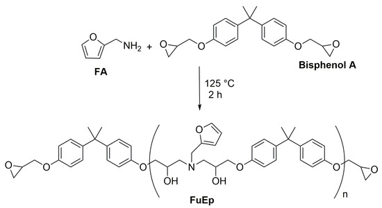
Scheme 1.
Synthesis of epoxyfuran oligomer FuEp.
2.2. Preparation of Polymer Mixtures
FGE, BMI, iso-MTHFA, 2-MI accelerator, and FuEp were used to produce multicomponent binders with a self-healing effect. The content of FuEp was 80 wt% of 100 wt% FGE. The amount of BMI participating in the thermoreversible reaction was 0.3 to 1 FGE in terms of molar ratios, since the addition of a larger amount of BMI complicates the mixing of the reagents. The content of iso-MTHFA was 90 wt% of the FGE mass and 20 wt% of the FuEp mass; 2-MI was 0.2 wt% of the total FGE and FuEp mass. To prepare multicomponent binders, BMI was dissolved in iso-MTHFA at a temperature of 90–100 °C for 5–10 min. FuEp was dissolved in FGE at 70–80 °C for 10 min. The resulting compositions were stirred at 90 °C for 5 min, and the 2-MI accelerator was added. As a binder for reference samples, we used a composition based on the epoxy oligomer CHS EPOXY 520 (100 wt%), which was cured with iso-MTHFA (90 wt%) and 2-MI (0.2 wt%) accelerator.
2.3. CFRP Production
For the manufacture of carbon plastic as a reinforcing material, plain weave carbon fabric based on Toray fibers (3K) brand GG200T (EU, Italy) was used. To form the package, the carbon fabric was cut into strips of 50 × 200 mm. The number of layers in the package was 7. The cut fabric was laid out in layers on a metal hot mold, and then each layer was impregnated with the prepared binder, the mold was closed, and pressure was applied to remove excess binder and shape the sample. During the formation of the package between the layers in the middle region of the sample, a Teflon film 10 mm wide was laid to create an edge crack in the samples. Plates based on binders with a self-healing effect were cured at 80 °C for 48 h, with plates based on a reference binder— 140 °C for 4 h. After curing, the mold for pressing was disassembled and plates 200 mm long, 50 mm wide, and 2 mm thick were removed from them. Samples were cut from these plates for DMA testing and GIR crack resistance determination by splitting a double-cantilever beam.
2.4. Characterization and Measurement
Thermogravimetric analysis (TGA) was performed on NETZSCH TG 209 F1 Libra (Selb, Germany) within a temperature range of 30 to 550 °C at a heating/cooling rate of 10 K min−1 in an argon atmosphere. The method of differential scanning calorimetry (DSC) (NETZSCH DSC 204 F1 Phoenix, Selb, Germany) was used to determine the thermal characteristics of binders in the measurement temperature range of 15–200 °C, with a heating rate of 10 K/min−1 in argon atmosphere. DMA measurements were carried out according to a three-point loading scheme on a DMA 242 E Artemis analyzer (Netzsch, Selb, Germany) at a temperature of 30 °C. The load application frequency was: 0.25; 0.5; 1.0; 3.3; 10.0 Hz. The CFRP samples were plates 30 mm long, 7 mm wide, and 2 mm thick. The distance between the supports is 20 mm. During the measurement, the value of the modulus of elasticity E’ was determined. The measurements were performed in three stages. At the first stage, the elastic modulus E’ of the original samples (without notch) was determined, which were obtained after curing. Then, cracks were set at the ends of the sample at 0.5 (i.e., for sample length ls = 30 mm and crack length lc = 15 mm, ratio lc/ls = 0.5) and 0.25 (lc/ls = 0.25), of its length, and E’ was measured under the same conditions as in the first stage. At the third stage, the measurements were carried out after heat treatment (self-healing cycle) at 120 °C for 25 min and 80 °C for 24, 48, and 72 h. The degree of self-healing of the CFRP was calculated as the ratio of the modulus of elasticity after heat treatment of the notched sample to the modulus of elasticity of the initial (intact) sample.
Before heat treatment, it was necessary to bring the surface of the applied crack into contact. For that purpose, force was applied to the samples using clamps (Figure 1). The samples were wrapped in a Teflon film to avoid contact and possible sticking together, and then (Figure 1 (3)) they were clamped between clamps, in which steel corners (Figure 1 (2)) and rubber (Figure 1 (4)) were installed to evenly distribute the load and to control the set force.
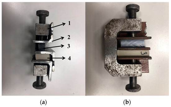
Figure 1.
Samples clamped in a clamp for heat treatment: 1—clamp for clamping samples; 2—steel corners; 3—samples wrapped in Teflon film; 4—rubber. (a) Front view; (b) Side view.
To determine the force applied to the samples, the rubber tabs were calibrated with a universal testing machine. For each rubber tab, a diagram of the applied force F versus deformation Δl during compression was recorded. From the obtained diagram, the compression force of the samples was determined by comparing the change in the thickness of the rubber after clamping with the deformation on the obtained curve F vs. Δl. Thus, the specified load was about 500 N.
The GIR crack resistance of CFRP was determined on a Zwick/Roell Z100 universal testing machine by splitting a double-cantilever beam. The original plates of carbon plastic were cut so that the Teflon film was in the cutting zone of samples for measuring crack resistance, and this was the initial crack. As a result, two samples were obtained for each binder with a length of 110 mm, a width of 18 mm, and a thickness of 2 mm. Before testing, the initial crack was artificially grown a little. At the edges of the samples, cuts were symmetrically applied at a distance of about 5 mm from the end of the sample. These cuts are necessary to secure the wire loops and to apply the force necessary for crack growth. The speed rate of the clamps during the test was 30 mm/min. The sample was loaded until the crack grew to a length of about 10 mm, after which the sample was photographed to determine the bending angles of the cantilevers α1 and α2 (see Figure 2) and the load was removed. Then, the loading-unloading cycle was repeated 5–6 times. For each loading cycle, the GIR crack resistance was determined using Formula [28]:
where w is the sample width.
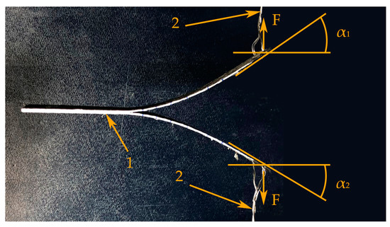
Figure 2.
Sample of a double-cantilever beam at the end of a loading cycle; technique for determining the bending angles of cantilevers α1 and α2. 1—Carbon fiber sample, 2—Grippers.
After each loading-unloading cycle, the length of the crack was determined by measuring the samples from the center of the fastening to the mark of the growth of the next crack. During the test, the dependence of the force on the crack opening was recorded.
After completion of the recovery test cycle, the samples were placed between two clamps in the same order as described above (Figure 1). Then, the CFRP samples were subjected to heat treatment at 120 °C for 25 min and at 80 °C for 48 h. After such heat treatment of the samples, their crack resistance was determined by the method described above. The degree of self-healing of CFRP was calculated as the ratio of the GIR value after heat treatment of a sample with a notch to the GIR value of a sample without a notch.
The study of cracks in carbon plastic before and after heat treatment was carried out by X-ray tomography on samples used to determine the elasticity modulus by DMA. The samples were scanned on a Bruker SkyScan 1172 X-ray microtomograph (Kontich, Belgium) using the SkyScan program according to the mode: voltage 40 kV, current 100 mA, resolution 4 μm, rotation step 0.2 deg, exposure time 500 ms, scanning time 4 h. A set of shadow projections of samples was obtained as a result of scanning, on the basis of which the reconstruction was carried out in the NRecon program using the Feldkamp algorithm. When previewing the cross sections, the reconstruction parameters were selected (smoothing (1…10) 2 units, ring artifact correction 10%, radiation hardness correction 0%, and the number of obtained sections 1000) and so was the dynamic range of the image using a histogram. A total of 1000 sections were obtained as a result of such a reconstruction. Images of three-dimensional models of samples were obtained using the CTvox program included in the software package for the tomograph. The Marching Cube algorithm, which is a surface construction algorithm based on the explicit hexagonal voxel model developed by Lorensen and Kline (1987), was used to build volumetric models. The scanning area of the samples is shown in Figure 3. The tomograms of the samples in two projections were obtained based on the reconstruction in the Data Viewer program. Morphometric analysis and calculation of porosity were performed using the CTAn program (Bruker). In binary images mode (images with binary grayscale display on the display), white corresponds to areas with brightness within the binary threshold value “solid”, and areas outside this range correspond to black—“blank”. For the correct display of voids and areas with high density, the optimal range of values on the brightness distribution histogram (55–255 grayscale) is selected. Using the function of three-dimensional analysis, the porosity was calculated over the entire volume of the sample.
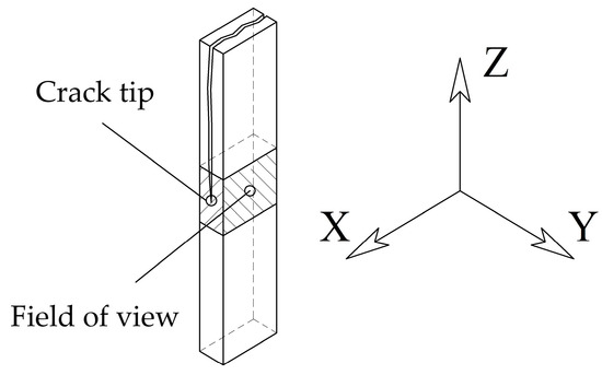
Figure 3.
Scheme of scanning samples of carbon plastics.
3. Results and Discussion
3.1. Thermal Properties
Figure 4 shows TGA and DTG curves for samples of reducing binders cured at 80 °C for 24, 72, and 144 h.
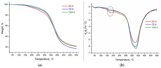
Figure 4.
TGA (a) and DTG (b) curves of binder samples cured at 80 °C.
The temperature characteristics of the binder samples are presented in Table 1. As the curing time increases, the heat resistance of the samples increases, and the decomposition temperature increases from 191 to 237 °C. The maximum decomposition temperature for all three samples is almost the same and is about 378 °C, which is typical for epoxy resins based on FGE and bismaleimides [8]. The DTG curves for compositions 1 and 2 (Figure 4) show a slight broadened mass loss peak at 178 °C, which may be caused by the evaporation of FGE remaining in the mixture. In the case of a fully cured composition, this peak is not observed. The ash residue for all three compositions is approximately the same and is about 20%. The sample aged for 24 h showed a slightly faster rate of decomposition compared to the samples that had a longer aging time. Apparently, this effect is associated with the formation of a looser polymer network and with the incompleteness of the reaction of epoxy groups, since the residual FGE peak on the DTG curve for this sample is more intense. The content of dynamic DA-adducts (DA-adducts) in this sample may be reduced, since the DA-reaction is a rather slow process.

Table 1.
Thermal properties of binder samples.
The thermal characteristics of the binder and the reversible nature of DA-bonds were analyzed by DSC. So, on the curves of the first heating of all samples (Figure 5), there are two clear endothermic peaks. The peak at a lower temperature (72, 92, and 106 °C for samples 1, 2, and 3, respectively) may be due to the melting of DA-adducts and oligoepoxides [29]. The peak at 72–106 °C refers to the melting of DA-adducts and oligoepoxides. Samples with different curing times contain oligoepoxy fragments with different molecular weights. The longer the curing time of the sample, the higher the molecular weight of the polymer, which is explained by a shift in the melting temperature to higher temperatures. This behavior is typical of both conventional epoxy resins [30], and for resins with dynamic DA-adducts [31]. An increase in this temperature is most likely due to an increase in the content of bicyclic adducts formed during the Diels–Alder reaction (with an increase in the duration of exposure at 80 °C, the proportion of DA-adducts also increases), as well as an increase in the molecular weight of oligoepoxides. The broadened peak at ~120 °C can be attributed to the reverse Diels–Alder reaction. As a result of the DA-reaction, as a rule, two types of isomers are formed: kinetic (endo) and thermodynamic (exo). The first type usually has a lower temperature of the reverse DA-reaction [8,32]. On the curves of the second heating, there are no signals indicating the splitting of dynamic DA-crosslinks, which indicates the completeness of the rDA-reaction. The curves of the second heating also show a transition at 47 °C, which corresponds to the vitrification of oligoepoxy fragments.
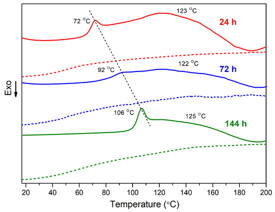
Figure 5.
DSC curves of binder samples with self-healing effect (solid line—first heating, dashed line—second heating).
3.2. Evaluation of the Degree of Recovery of CFRP by the DMA Method
Figure 6 shows the elastic modulus E’ at different frequencies for CFRP samples based on a binder with a self-healing effect (with thermoreversible bonds) and a reference sample. For all the studied samples, the modulus of elasticity practically does not change after 1 Hz. The values of E’ for CFRP samples based on binders with thermoreversible bonds (~24 GPa) are two times lower than those for control samples (~53 GPa). Quite often, non-linear dependences of strength or elastic modulus on loading rate are observed when determining mechanical characteristics in a wide range of loading rates, which are associated with changes in the fracture mechanism or the response of the material to external influences [33,34,35]. In our case, the change in the elastic modulus with increasing loading rate is associated with the transition from quasi-static loading rates (less than 1 Hz) to dynamic ones. Notches significantly reduce the modulus of elasticity CFRP. When a crack is applied with a length of 0.25 of the total length of the sample, the values of the modulus E’ decrease to ~41 GPa for control CFRP and to ~20 GPa for CFRP based on a binder with thermoreversible bonds. Even more noticeably, the elastic modulus decreases at a notch equal to 0.5 of the sample length: to ~17 GPa for the control CFRP and to ~13 GPa for CFRP with the self-healing effect. Thus, it can be argued that the chosen parameter (elastic modulus E’) is sensitive to the presence of a crack.
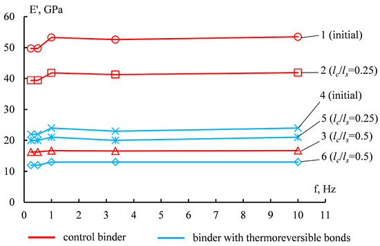
Figure 6.
Elastic modulus E’ of CFRP based on control binder (1, 2, 3) and binder with thermoreversible bonds (4, 5, 6). 1, 4—reference sample; 2, 5—with crack 0.25; 3, 6—with crack 0.5.
Figure 7 shows the curves of E’ versus f for samples of CFRP based on a binder with a self-healing effect with a relative crack length of 0.25 for different times of the self-healing process at 80 °C exposure. It can be seen that the values of the modulus of elasticity E’ CFRP after heat treatment (curve 3) are higher than the values of E’ after cracking (curve 2) and approach the level of the modulus of elasticity for CFRP samples without a notch (curve 1).
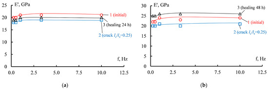
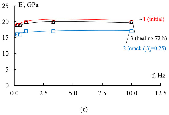
Figure 7.
Elastic modulus E’ of samples of CFRP based on a binder with thermoreversible bonds: after 120 °C for 25 min and at 80 °C for 24 h (a); 48 h (b) and 72 h (c); 1—reference sample; 2—with crack 0.25, 3—after heat treatment.
A similar change in elastic modulus levels for heat-treated CFRP, after a self-healing cycle, is observed for samples with a notch of 0.5 relative to the total length (Figure 8). It should be noted that even with an increase in the length of the notch and the subsequent decrease in the elastic modulus (curve 2), after heat treatment, the values of E’ (curve 3) approach the reference level (curve 1).
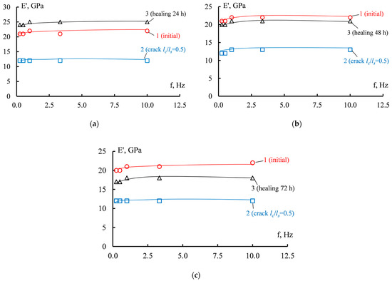
Figure 8.
Modulus of elasticity E’ of CFRP samples based on a binder with thermoreversible bonds: after 120 °C for 25 min and at 80 °C for 24 h (a); 48 h (b) and 72 h (c); 1—reference sample; 2—with crack 0.5, 3—after heat treatment.
Figure 9 shows the elastic modulus E’ versus holding time at 80 °C. It can be seen that all values of the modulus of elasticity of the samples after heat treatment are higher than the values of E’ CFRP without heat treatment of the cracked samples. For both types of samples with a relative crack length of 0.25 and 0.5, a decrease in the elastic modulus is observed after 48 h. The E’ values of samples with a crack of 0.25 and 0.5 at 48 h are closest to the E’ values of the reference sample.
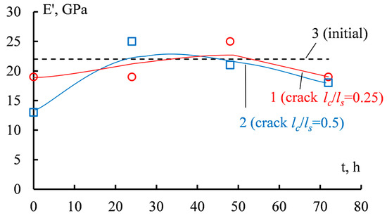
Figure 9.
Change in the elastic modulus E’ of samples after holding at 120 °C for 25 min and at 80 °C for different periods of time. 1—0.25; 2—0.5; 3—reference sample without heat treatment.
Thus, it can be assumed that the most optimal exposure time for samples during heat treatment is 48 h. Based on this, heat treatment of CFRP macrosamples for crack resistance was carried out at 120 °C for 25 min and at 80 °C for 48 h.
The generalized data on the self-healing effects of CFRP at different heat treatment times are shown in the Table 2.
Table 2.
Degree of self-healing α (%) CFRP with different relative crack length and heat treatment time.
Table 2 shows that the degree of recovery of the modulus of elasticity E’ exceeds 80% for all modes of heat treatment and relative crack lengths in CFRP. Regardless of the relative crack length, heat treatment should be carried out for no more than 48 h. In this case, the degree of self-healing can be more than 100%. The effect may be related to the healing of small defects in samples during heat treatment [36].
3.3. Evaluation of the Degree of Recovery of Carbon Plastics during Delamination of a Macrosample
Figure 10 shows the load curves for CFRP based on a thermoreversible binder before and after heat treatment. The CFRP samples that are delaminated for the first time (Figure 10a), before reaching the critical force or the maximum load at which the crack grows, are deformed elastically. After reaching the maximum force, the crack grows, which is accompanied by load fluctuations. Load fluctuations indicate that the rate of crack propagation is not constant. After the crack had grown to a predetermined length, the sample was unloaded. Then, the cycle of loading—crack growth—unloading was repeated several times. For secondarily layered CFRP, i.e., after crack propagation and heat treatment, the load diagrams do not change. At the same time, the character of crack propagation remains unchanged. It should be noted that the level of critical load peaks in “recovered” CFRP is lower. Preservation of the form of loading diagrams for macrosamples of carbon plastics before and after the recovery cycle indicates that the “healing” process in damaged materials is possible [37,38].
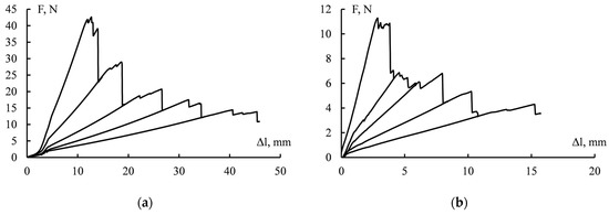
Figure 10.
Loading diagram of CFRP samples before (a) and after (b) self-healing.
In Figure 11, for both samples with the effect of self-healing, the values of crack resistance are shown separately from the length of the crack before and after heat treatment. The GIR values noticeably decrease with increasing crack length. Such a change in the crack resistance parameter as a function of the crack length is not typical for fibrous reinforced plastics based on matrices without the self-healing effect. Typically, crack resistance remains virtually unchanged with crack lengthening or may increase. An increase in crack resistance parameters is associated with the formation and development of strands during crack growth [39]. In this case, the formation of strands was not observed during CFRP delamination. Probably, such a mechanism of CFRP delamination is associated with the elastic-strength properties of the matrix.
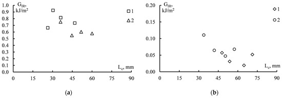
Figure 11.
Crack resistance of GIR CFRP based on a binder with thermally reversible bonds depending on the length of the crack Lc before (a) and after (b) self-healing. 1—sample No. 1; 2—sample No. 2.
The average values of the GIR crack resistance of CFRP before and after the self-healing process are given in Table 3. For comparison, the table shows the crack resistance of CFRP based on an anhydride-cured epoxy matrix. It should be noted that the value of GIR CFRP obtained on the basis of the synthesized FuEp oligomer (80 wt.%) is higher by 70% than the crack resistance values of the reference sample. Such a high crack resistance is characteristic of CFRP based on epoxy matrices modified with thermoplastics (polysulfone, polyethersulfone, polyetherimide, etc.) and can reach 0.6 kJ/m2 [38,40].
Table 3.
Crack resistance of carbon fiber reinforced plastics based on a binder for comparison and a binder with a self-healing effect.
After carrying out the CFRP recovery mode with a germinated macrocrack, the GIR values decrease by an order of magnitude compared to the reference sample. The degree of self-healing of crack resistance values for macro-samples was about 7%.
It can be concluded that the restoration of crack resistance values on massive samples is less effective than on samples with smaller dimensions. This may also be due to the fact that when splitting the samples, the matrix can break off from the reinforcing material, and when the surfaces come into contact, the existing volume of the matrix will not be enough to fully restore the material.
3.4. X-ray Tomography of CFRP
Table 4 shows the porosity of GFRP based on the control matrix and matrix with the effect of recovery. It can be seen that the porosities of GFRP with the reduction effect and control samples have similar values (2.5 and 3.1 vol.%, respectively). After crack healing in self-healing CFRP samples, the porosity tends to decrease and is almost equal to that of the control samples.
Table 4.
Porosity of CFRP based on a binder for comparison and a binder with a self-healing effect.
Figure 12 and Figure 13 show X-ray tomograms of compact CFRP samples before and after a reduction process of several hours at 80 °C. On samples with relative crack lengths of 0.25 and 0.5 before recovery (Figure 12a and Figure 13a), delamination is visible along the entire length of the sections in the XY and ZY planes (a). The bundles (a) extend between and through the layers (b) of the fabric. The thickness of the matrix (c) between the layers of the reinforcing filler (b) is 15–40 microns. The opening of a crack is the distance between its surfaces in the investigated section of about 20–50 microns. Pores (d) with sizes of 150–220 µm are also visible. The pores are arranged randomly throughout the volume of the samples.
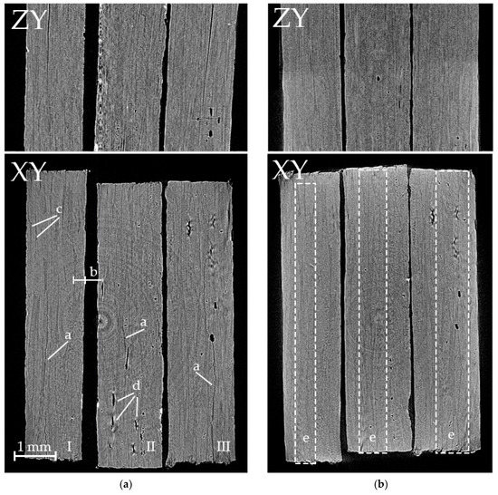
Figure 12.
Tomograms of samples of CFRP with a relative crack length of 0.25 before (a) and after (b) recovery for an 24 h (I), 48 h (II) and 72 h (III) at 80 °C. a—crack, b—layer of reinforcing fibers, c—matrix, d—pores, e—defect region.
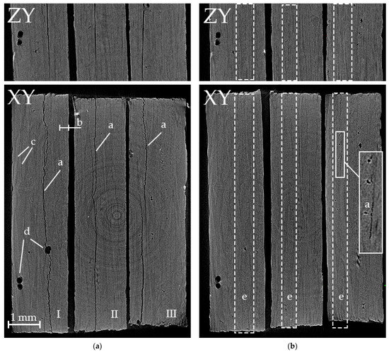
Figure 13.
Tomograms of samples of CFRP with a relative crack length of 0.5 before (a) and after (b) recovery for an 24 h (I), 48 h (II) и 72 h (III) at 80 °C. a—crack, b—layer of reinforcing fibers, c—matrix, d—pores, e—defect region.
From Figure 12b and Figure 13b, it can be seen that for samples heat-treated for 24 h (I) and 48 h (II), the specified defects are not identified (region (e)). However, a decrease in the size of large pores (d) was observed after heat treatment of the samples. Characteristic pores were used to identify the corresponding cross sections after CFRP heat treatment.
Thus, it can be concluded that the selected heat treatment mode and the applied contact pressure provide a high degree of recovery of the CFRP properties (see Table 2). In addition, the number and size of pores in the material decreases, which ultimately contributes to an increase in the physical and mechanical characteristics of the material. The decrease in defectiveness can explain the values of the degree of recovery of more than 100%.
Microcracks (a) and pores (d) in region (e) were found in the volume of CFRP samples heat-treated for 72 h. For the CFRP sample, with a relative length of the initial crack of 0.25, extended closed pores 300–500 µm long and 50–70 µm wide are observed along the fracture surfaces that were in the crack volume before repair (Figure 12b). In a CFRP sample with a relative length of the initial crack of 0.5, areas with an unhealed crack (a) 20–30 µm wide and pores (d) 30–60 µm in size were found (Figure 13b). Apparently, the presence of remaining defects resulted in lower values of the modulus of elasticity E’ at the maximum heat treatment time (see Figure 9).
4. Conclusions
Layered carbon fiber reinforced plastics based on a thermoreversible epoxy binder were studied by dynamic mechanical analysis and delamination of a double-cantilever beam.
The presence of reversibly cleaving DA-adducts in the binder samples was qualitatively confirmed by DSC. All adducts successfully reversed the DA-reaction during the course of the assay.
It is shown that the DMA method with three-point bending of notched CFRP samples can be sensitive for determining the effects of self-healing carbon plastics based on matrices with thermoreversible bonds. As a criterion for the degree of restoration of properties, the ratio of the elasticity modulus E’ of notched samples and the elasticity modulus after the heat treatment process was chosen. The degree of recovery of the modulus of elasticity E’ CFRP exceeds 80% for all modes of heat treatment and relative crack lengths in CFRP. Regardless of the relative length of the crack in the CFRP, heat treatment could be achieved in 48 h.
The degree of restoration of the crack resistance parameter GIR on massive samples with macrolamination is noticeably lower than for compact samples with micronotches. The value of the crack resistance parameter GIR for CFRPP in the field of the heat treatment process is 0.05 kJ/m2, and the degree of reduction is 7%. It should be noted that the crack resistance of CFRP samples with thermally reversible bonds is much higher (0.7 kJ/m2) than the values for samples based on the “classical” system––for example, CHS EPOXY 520 + iso-MTHFA + 2-MI (0.41 kJ/m2).
The study of cracks before and after self-healing by X-ray tomography showed that during the heat treatment cycle, the crack “overgrows”, while the defects (pores) formed during the manufacture of the sample decrease in size. This result may be due to the fact that for some samples of CFRP, the degree of recovery is more than 100%.
Author Contributions
Conceptualization, T.V.P., V.I.S., G.Y.Y. and A.A.B.; methodology, T.V.P., V.I.S., I.V.T., A.V.K., E.O.P. and P.F.P.; investigation, T.V.P., V.I.S., I.V.T., A.V.K., E.O.P. and P.F.P.; formal analysis, T.V.P., I.V.T., A.V.K., E.O.P. and P.F.P.; writing—original draft preparation, T.V.P., V.I.S., O.V.A., E.O.P., P.F.P. and A.A.B.; writing—review and editing, V.I.S., O.V.A. and E.O.P.; supervision, V.I.S., G.Y.Y. and A.A.B.; project administration, O.V.A. and V.I.S. All authors have read and agreed to the published version of the manuscript.
Funding
This research received no external funding.
Institutional Review Board Statement
Not applicable.
Informed Consent Statement
Not applicable.
Data Availability Statement
The data presented in this study are available on request from the corresponding author.
Conflicts of Interest
The authors declare no conflict of interest.
References
- Zhang, M.; Rong, M. Design and synthesis of self-healing polymers. Sci. China Chem. 2012, 55, 648–676. [Google Scholar] [CrossRef]
- Zhang, Z.P.; Rong, M.Z.; Zhang, M.Q. Polymer engineering based on reversible covalent chemistry: A promising innovative pathway towards new materials and new functionalities. Prog. Polym. Sci. 2018, 80, 39–93. [Google Scholar] [CrossRef]
- Nik Md Noordin Kahar, N.N.F.; Osman, A.F.; Alosime, E.; Arsat, N.; Mohammad Azman, N.A.; Syamsir, A.; Itam, Z.; Abdul Hamid, Z.A. The Versatility of Polymeric Materials as Self-Healing Agents for Various Types of Applications: A Review. Polymers 2021, 13, 1194. [Google Scholar] [CrossRef]
- Teixeira, R.F.A.; Hillewaere, X.K.D.; Billiet, S.; Du Prez, F.E. Chemistry of Crosslinking Processes for Self-Healing Polymers. Macromol. Rapid Commun. 2013, 34, 290–309. [Google Scholar] [CrossRef]
- Zhai, L.; Narkar, A.; Ahn, K. Self-healing polymers with nanomaterials and nanostructures. Nano Today 2020, 30, 100826. [Google Scholar] [CrossRef]
- Wang, Y.; Pham, D.T.; Ji, C. Nanocomposites for Extrinsic Self-healing Polymer Materials. In Smart Polymer Nanocomposites: Energy Harvesting, Self-Healing and Shape Memory Applications; Ponnamma, D., Sadasivuni, K.K., Cabibihan, J.-J., Al-Maadeed, M.A.-A., Eds.; Springer International Publishing: Cham, Switzerland, 2017; pp. 243–279. [Google Scholar] [CrossRef]
- Utrera-Barrios, S.; Verdejo, R.; López-Manchado, M.A.; Hernández Santana, M. Evolution of self-healing elastomers, from extrinsic to combined intrinsic mechanisms: A review. Mater. Horiz. 2020, 7, 2882–2902. [Google Scholar] [CrossRef]
- Wang, X.; Zhao, K.; Huang, X.; Ma, X.; Wei, Y. Preparation and properties of self-healing polyether amines based on Diels–Alder reversible covalent bonds. High Perform. Polym. 2019, 31, 51–62. [Google Scholar] [CrossRef]
- Beljaars, M.; Heeres, H.J.; Broekhuis, A.A.; Picchioni, F. Bio-Based Aromatic Polyesters Reversibly Crosslinked via the Diels–Alder Reaction. Appl. Sci. 2022, 12, 2461. [Google Scholar]
- Liu, Y.-L.; Chuo, T.-W. Self-healing polymers based on thermally reversible Diels–Alder chemistry. Polym. Chem. 2013, 4, 2194–2205. [Google Scholar] [CrossRef]
- Gandini, A. The furan/maleimide Diels–Alder reaction: A versatile click–unclick tool in macromolecular synthesis. Prog. Polym. Sci. 2013, 38, 1–29. [Google Scholar] [CrossRef]
- Lee, Y.-H.; Zhuang, Y.-N.; Wang, H.-T.; Wei, M.-F.; Ko, W.-C.; Chang, W.-J.; Way, T.-F.; Rwei, S.-P. Fabrication of Self-Healable Magnetic Nanocomposites via Diels–Alder Click Chemistry. Appl. Sci. 2019, 9, 506. [Google Scholar] [CrossRef]
- Tian, Q.; Yuan, Y.C.; Rong, M.Z.; Zhang, M.Q. A thermally remendable epoxy resin. J. Mater. Chem. 2009, 19, 1289–1296. [Google Scholar] [CrossRef]
- Coope, T.; Turkenburg, D.; Fischer, H.; Luterbacher, R.; Bracht, H.; Bond, I. Novel Diels-Alder based self-healing epoxies for aerospace composites. Smart Mater. Struct. 2016, 25, 084010. [Google Scholar] [CrossRef]
- Turkenburg, D.H.; Fischer, H.R. Diels-Alder based, thermo-reversible cross-linked epoxies for use in self-healing composites. Polymer 2015, 79, 187–194. [Google Scholar] [CrossRef]
- Wu, D.Y.; Meure, S.; Solomon, D. Self-healing polymeric materials: A review of recent developments. Prog. Polym. Sci. 2008, 33, 479–522. [Google Scholar] [CrossRef]
- Perin, D.; Odorizzi, G.; Dorigato, A.; Pegoretti, A. Development of Polyamide 6 (PA6)/Polycaprolactone (PCL) Thermoplastic Self-Healing Polymer Blends for Multifunctional Structural Composites. Appl. Sci. 2022, 12, 12357. [Google Scholar] [CrossRef]
- Oh, C.-R.; Lee, D.-I.; Park, J.-H.; Lee, D.-S. Thermally Healable and Recyclable Graphene-Nanoplate/Epoxy Composites via an In-Situ Diels-Alder Reaction on the Graphene-Nanoplate Surface. Polymers 2019, 11, 1057. [Google Scholar] [CrossRef] [PubMed]
- Wu, P.; Liu, L.; Wu, Z. Synthesis of Diels-Alder Reaction-Based Remendable Epoxy Matrix and Corresponding Self-healing Efficiency to Fibrous Composites. Macromol. Mater. Eng. 2020, 305, 2000359. [Google Scholar] [CrossRef]
- Chen, X.; Dam, M.A.; Ono, K.; Mal, A.; Shen, H.; Nutt, S.R.; Sheran, K.; Wudl, F. A Thermally Re-mendable Cross-Linked Polymeric Material. Science 2002, 295, 1698–1702. [Google Scholar] [CrossRef]
- Khan, N.I.; Halder, S.; Wang, J. Diels-Alder based epoxy matrix and interfacial healing of bismaleimide grafted GNP infused hybrid nanocomposites. Polym. Test. 2019, 74, 138–151. [Google Scholar] [CrossRef]
- Kuang, X.; Liu, G.; Dong, X.; Liu, X.; Xu, J.; Wang, D. Facile fabrication of fast recyclable and multiple self-healing epoxy materials through diels-alder adduct cross-linker. J. Polym. Sci. Part A Polym. Chem. 2015, 53, 2094–2103. [Google Scholar] [CrossRef]
- Tian, Q.; Rong, M.Z.; Zhang, M.Q.; Yuan, Y.C. Synthesis and characterization of epoxy with improved thermal remendability based on Diels-Alder reaction. Polym. Int. 2010, 59, 1339–1345. [Google Scholar] [CrossRef]
- Tian, Q.; Rong, M.Z.; Zhang, M.Q.; Yuan, Y.C. Optimization of thermal remendability of epoxy via blending. Polymer 2010, 51, 1779–1785. [Google Scholar] [CrossRef]
- McReynolds, B.T.; Mojtabai, K.D.; Penners, N.; Kim, G.; Lindholm, S.; Lee, Y.; McCoy, J.D.; Chowdhury, S. Understanding the Effect of Side Reactions on the Recyclability of Furan–Maleimide Resins Based on Thermoreversible Diels–Alder Network. Polymers 2023, 15, 1106. [Google Scholar] [CrossRef]
- Czifrak, K.; Lakatos, C.; Karger-Kocsis, J.; Daróczi, L.; Zsuga, M.; Keki, S. One-Pot Synthesis and Characterization of Novel Shape-Memory Poly(ε-Caprolactone) Based Polyurethane-Epoxy Co-networks with Diels–Alder Couplings. Polymers 2018, 10, 504. [Google Scholar] [CrossRef] [PubMed]
- Kotrotsos, A.; Rouvalis, C.; Geitona, A.; Kostopoulos, V. Toughening and Healing of CFRPs by Electrospun Diels–Alder Based Polymers Modified with Carbon Nano-Fillers. J. Compos. Sci. 2021, 5, 242. [Google Scholar] [CrossRef]
- Solodilov, V.I.; Bazhenov, S.L.; Gorbatkina, Y.A.; Kuperman, A.M. Determination of the Interlaminar Fracture Toughness of Glass-Fiber-Reinforced Plastics on Ring Segments. Mech. Compos. Mater. 2003, 39, 407–414. [Google Scholar] [CrossRef]
- Dolci, E.; Michaud, G.; Simon, F.; Boutevin, B.; Fouquay, S.; Caillol, S. Remendable thermosetting polymers for isocyanate-free adhesives: A preliminary study. Polym. Chem. 2015, 6, 7851–7861. [Google Scholar] [CrossRef]
- Hardis, R.; Jessop, J.L.P.; Peters, F.E.; Kessler, M.R. Cure kinetics characterization and monitoring of an epoxy resin using DSC, Raman spectroscopy, and DEA. Compos. Part A Appl. Sci. Manuf. 2013, 49, 100–108. [Google Scholar] [CrossRef]
- Fortunato, G.; Anghileri, L.; Griffini, G.; Turri, S. Simultaneous Recovery of Matrix and Fiber in Carbon Reinforced Composites through a Diels–Alder Solvolysis Process. Polymers 2019, 11, 1007. [Google Scholar] [CrossRef]
- Liu, Y.-L.; Hsieh, C.-Y. Crosslinked epoxy materials exhibiting thermal remendablility and removability from multifunctional maleimide and furan compounds. J. Polym. Sci. Part A Polym. Chem. 2006, 44, 905–913. [Google Scholar] [CrossRef]
- Al-Zubaidy, H.; Zhao, X.-L.; Al-Mihaidi, R. Mechanical Behaviour of Normal Modulus Carbon Fibre Reinforced Polymer (CFRP) and Epoxy under Impact Tensile Loads. Procedia Eng. 2011, 10, 2453–2458. [Google Scholar] [CrossRef]
- Suvorova, Y.V.; Sorina, T.G.; Gunyaev, G.M. Rate dependences of the strength of carbon-fiber-reinforced plastics. Mech. Compos. Mater. 1991, 26, 480–484. [Google Scholar] [CrossRef]
- Harding, J.; Welsh, L.M. A tensile testing technique for fibre-reinforced composites at impact rates of strain. J. Mater. Sci. 1983, 18, 1810–1826. [Google Scholar] [CrossRef]
- Ding, S.; Zhang, J.; Zhou, L.; Luo, Y. Promoting healing progress in polymer composites based on Diels-Alder reaction by constructing silver bridges. Polym. Adv. Technol. 2021, 32, 1239–1250. [Google Scholar] [CrossRef]
- Sørensen, B.F.; Jacobsen, T.K. Large-scale bridging in composites: R-curves and bridging laws. Compos. Part A Appl. Sci. Manuf. 1998, 29, 1443–1451. [Google Scholar] [CrossRef]
- Solodilov, V.I.; Korokhin, R.A.; Gorbatkina, Y.A.; Kuperman, A.M. Comparison of Fracture Energies of Epoxy-polysulfone Matrices and Unidirectional Composites Based on Them. Mech. Compos. Mater. 2015, 51, 177–190. [Google Scholar] [CrossRef]
- Jacobsen, T.K.; Sørensen, B.F. Mode I intra-laminar crack growth in composites-modelling of R-curves from measured bridging laws. Compos. Part A Appl. Sci. Manuf. 2001, 32, 1–11. [Google Scholar] [CrossRef]
- Korokhin, R.A.; Solodilov, V.I.; Zvereva, U.G.; Solomatin, D.V.; Gorbatkina, Y.A.; Shapagin, A.V.; Lebedeva, O.V.; Bamborin, M.Y. Epoxy polymers modified with polyetherimide. Part II: Physicomechanical properties of modified epoxy oligomers and carbon fiber reinforced plastics based on them. Polym. Bull. 2020, 77, 2039–2057. [Google Scholar] [CrossRef]


Disclaimer/Publisher’s Note: The statements, opinions and data contained in all publications are solely those of the individual author(s) and contributor(s) and not of MDPI and/or the editor(s). MDPI and/or the editor(s) disclaim responsibility for any injury to people or property resulting from any ideas, methods, instructions or products referred to in the content. |
© 2023 by the authors. Licensee MDPI, Basel, Switzerland. This article is an open access article distributed under the terms and conditions of the Creative Commons Attribution (CC BY) license (https://creativecommons.org/licenses/by/4.0/).