Article

Study on Seismic Reduction Measures of a Diaphragm Wall—Underground Structure System

1
The Key Laboratory of Urban Security and Disaster Engineering, Ministry of Education, Beijing University of Technology, Beijing 100124, China
2
The Beijing Key Laboratory of Urban Underground Space Engineering, School of Civil and Resource Engineering, University of Science and Technology Beijing, Beijing 100083, China
3
Department of Hydraulic Engineering, Tsinghua University, Beijing 100084, China
*
Author to whom correspondence should be addressed.
Appl. Sci. 2023, 13(12), 6910; https://doi.org/10.3390/app13126910
Submission received: 25 April 2023 / Revised: 29 May 2023 / Accepted: 3 June 2023 / Published: 7 June 2023
(This article belongs to the Special Issue Urban Underground Engineering: Excavation, Monitoring, and Control)

Abstract

:
In this paper, the seismic reduction and isolation measures are first proposed by setting a segmented isolation layer between the diaphragm wall and the side wall of the station structure. Although the segmented isolation layer can effectively improve the stress state of the side wall and slabs, the seismic reduction effect of the middle column is not obvious. In order to improve the overall seismic performance of the station structure, the reduction measures by combining the segmented isolation layer and new type bearing of the middle column are then proposed. At the same time of inserting the isolation layer between the diaphragm wall and the structure, the sliding bearing at the top of the column is set up to reduce the vibration. The results show that the segmented isolation layer can significantly reduce the internal force and damage at the top, bottom and side wall joints. In addition, the combined measures of segmented isolation layer and sliding bearing at the top of the column can effectively reduce the seismic damage of the middle column. The damage of the connection between the top plate, the middle plate and the middle column can be significantly decreased.

1. Introduction

The destructive effects of strong earthquakes on underground structures can be divided into two categories: damage caused by soil vibrations and damage caused by soil damage [1]. The presence of a diaphragm wall increases the lateral stiffness of the station structure and alters the relative stiffness ratio between the structure and soil, thereby impacting the seismic performance of the structure. When the diaphragm wall is jointly involved, the deformation characteristics, internal force distribution and failure mode of the structure will change to some extent [2,3,4]. The existence of the diaphragm wall will improve the seismic performance of the side wall, but also aggravate the seismic damage of some key parts of the station structure [2]. Zhuang et al. [4] compared the influences of the diaphragm wall and its connection to the side wall of the underground subway station. However, the composite wall connection can lead to more severe tensile damage at the connection between the top and bottom plate of the station structure and the side wall under the strong earthquake. Wang et al. [2] studied the seismic response law of the station structure under the conditions of neglecting the diaphragm wall and considering the single-layer and double-layer diaphragm walls for a cross-span subway station located at the liquefaction site. For different span subway station structures, the seismic response differs between those with a single-layer diaphragm wall and those with a double-layer diaphragm wall [2]. Additionally, the influence of the diaphragm wall is related to the buried depth of the subway station structure [5].
To explore effective measures for seismic reduction and isolation and enhance the seismic performance of underground structures, researchers have conducted a series of scientific research by using theoretical analysis [6,7], numerical simulation [8,9,10,11,12], and a model test [13]. These measures can be broadly divided into two categories. The first category involves modifying the characteristics of the structure itself, such as installing isolation devices at the ends of intermediate columns or other components. The second category involves incorporating an “energy dissipation” layer between the structure and soil to absorb a portion of seismic energy and mitigate the impact of ground motion on the structure.
Some researchers believe that improving the stress conditions and deformation characteristics of the central column is one of the effective methods to improve the seismic performance of an underground structure. The installation of a shear plate damper and lead rubber bearing at the top of the structural column has an obvious seismic reduction effect. The self-centering energy dissipation column can reduce the internal force of the central column and the interstory displacement of the structure under the earthquake [14,15,16].
Based on the seismic damage mechanism of the Daikai underground subway station during the Kobe earthquake, Ma et al. [17] found that the installation of sliding isolation bearings between the central column and the longitudinal beam can reduce the lateral deformation of the central column. Compared with the prototype structure, the overall lateral stiffness of the structure is significantly reduced after the friction swing bearing is set at the top of the middle column, while the truncated swing column can effectively improve the deformation and recovery capacity of the middle column [18]. Liu et al. [19] further proposed a circular groove roller bearing suitable for high axial pressure of underground station structure, and its effectiveness was verified through numerical analysis.
Another group of researchers focused on the isolation layer of underground structures and its effect on improving the seismic performance. Seyyed et al. [20] carried out the research on seismic reduction technology for underground tunnels and found that the use of seismic isolation materials with lower shear modulus can significantly enhance the overall seismic performance of the tunnel. For station structure, Kiryu et al. [21] found that inserting an “isolation wall” made of polymer material between the soil and the side wall of the structure can reduce the bending moment at the bottom of the side wall. The shock absorption capability of the partition wall depends on the thickness of the soil layer on the structure and the shear stiffness ratio between the soil and structure.
Based on the aforementioned research, it is evident that the seismic reduction and isolation measures for the middle column of underground structures mainly focus on improving the deformation capacity of the central column and reducing its internal forces. Although the seismic performance of the central column can be improved by setting various cushions and bearings, the internal forces of structural key components will also be changed. The internal forces shared by other components except the central column, such as side walls, beams and slabs, may increase significantly. Previous studies have shown that the middle column is the weakest component under earthquake action. However, the stress conditions of side walls, slabs and other key components should also be paid attention to. The collapse of the Daikai underground subway station is mainly caused by the damage of the top plate and the middle column; specifically, the cracks across the cross-section occur at the connection between the top plate, the side wall and the middle column. The top plate loses its vertical bearing capacity, resulting in the overlying earth pressure being fully borne by the middle column. Due to the large dynamic damage of the middle column itself, the central column and the top plate collapse as a whole. In summary, the seismic reduction and isolation measures for the central column have certain shortcomings and limitations. While strengthening the seismic capacity of the central column, it is unable to reasonably distribute the internal forces of the key components, so the overall seismic performance of the structure cannot be improved significantly. Although some researchers have explored isolation layer measures, most of them overlook the presence of envelope structures in actual engineering and directly place the isolation layer between the structure and the soil.

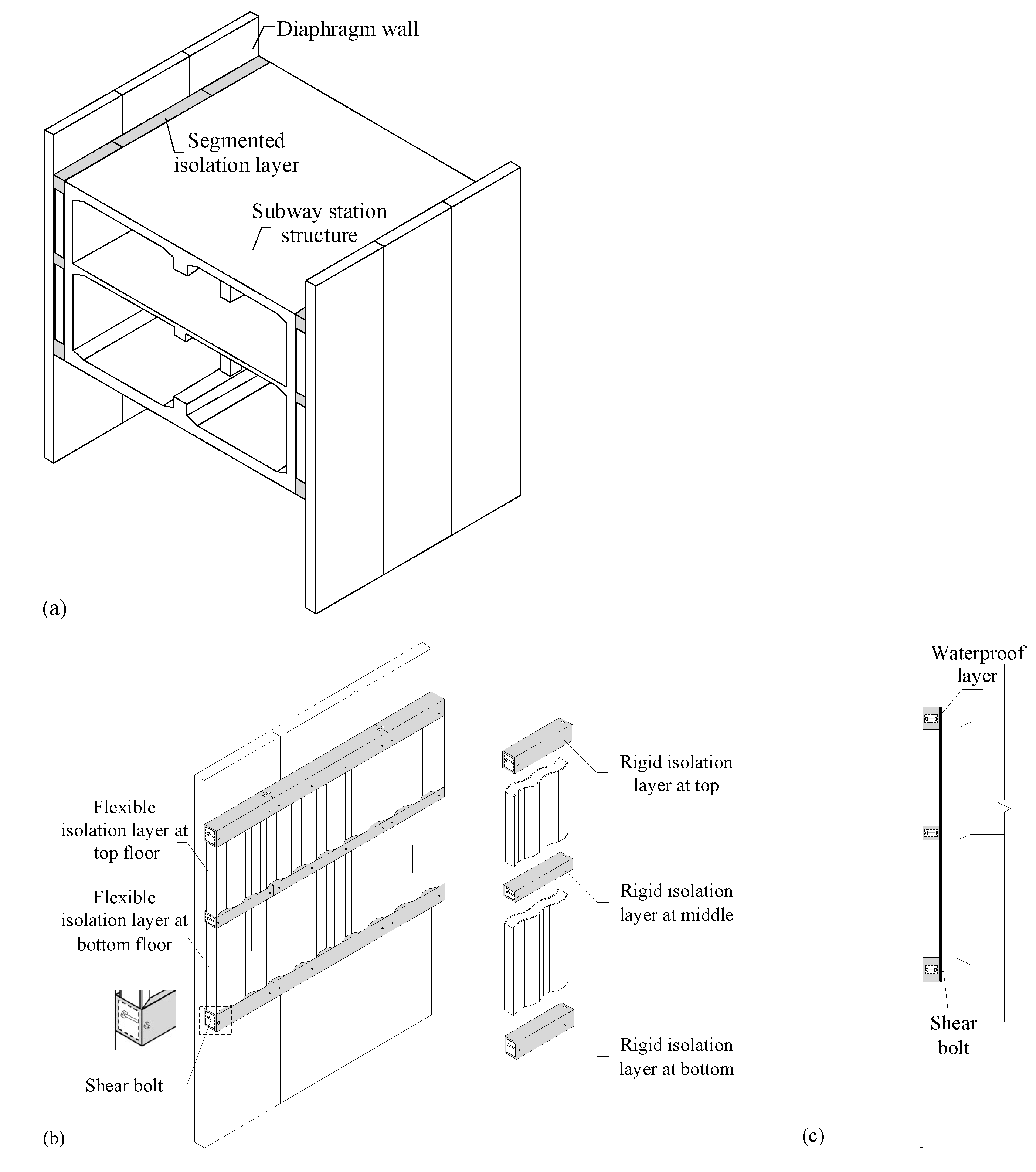
2. Underground Structure–Isolation Layer–Diaphragm Wall System

As the crucial seismic component of the subway station, the collapse of the central column and top plate occurs when the top plate is damaged and loses its vertical bearing capacity, leading to the complete transfer of overlying earth pressure onto the central column. To enhance the seismic resistance of the top plate, this paper proposes a vibration absorption technique by introducing a segmented isolation layer between the side wall and the diaphragm wall, on the premise that the horizontal deformation transfer function of the diaphragm wall and the side wall is ensured and the lateral deformation of the structure is basically unchanged. The seismic measures relax the rotation constraint of the diaphragm wall on the side wall, thus reducing the seismic response at the connection of top plate and the side wall. The purpose of this measure is to reduce the seismic internal force of the top plate and improve the overall seismic capacity of the station structure.
A segmented isolation layer is implemented between the side wall of the station structure and the diaphragm wall. The segmented isolation layer is mainly composed of two parts. The rigid isolation layer connected with the plate and partial wall structure. The rest parts are the flexible isolation layer. The system composed of the diaphragm wall and the station structure is shown in Figure 1a. The structural design of the segmented isolation layer measures is shown in Figure 1b. The three sections of the rigid isolation layer are connected with the station top plate, middle plate and bottom plate, respectively, to ensure the horizontal deformation transmission function of the underground diaphragm wall and side wall. The purpose is to keep the lateral deformation of the structure basically unchanged, so as to avoid the adverse situation that the deformation between the isolation layers of the station structure increases significantly due to the overall outsourcing of the flexible isolation layer. The rigidity of the flexible isolation layer is relatively small. When an earthquake is approaching, the top and bottom side walls can be allowed to have bending deformation within the safe range and reasonably distribute the internal forces of key structural members such as plates and side walls. The rigid isolation layer and the diaphragm wall can be consolidated into a whole through shear bolts, as shown in Figure 1c. Along the longitudinal direction of the diaphragm wall, the bolts connect the segmented rigid isolation layer into a whole through reserved bolt holes. The lower surface of the bottom rigid isolation layer is at the same horizontal elevation as the lower surface of the station bottom plate. Similarly, the upper surface of the top rigid isolation layer and the middle rigid isolation layer are flush with the upper surface of the station top plate and the station middle plate, respectively. The inner surface of the isolation layer is pasted with a waterproof layer. If groundwater seeps from the joint of the ground connecting wall, the waterproof layer can be effectively isolated. The flexible isolation layer is protected by the diaphragm wall, the rigid isolation layer and the station side wall, which avoids the possibility of erosion in direct contact with the soil and is conducive to extending its service life. The shear bolts connect the diaphragm wall, rigid isolation layer and station structure into a whole through the reserved bolt holes arranged on the left and right of the rigid isolation layer. The thickness of the rigid isolation layer along the depth direction of the diaphragm wall is the sum of the plate thickness and the plate support thickness.

2.1. Time History Analysis
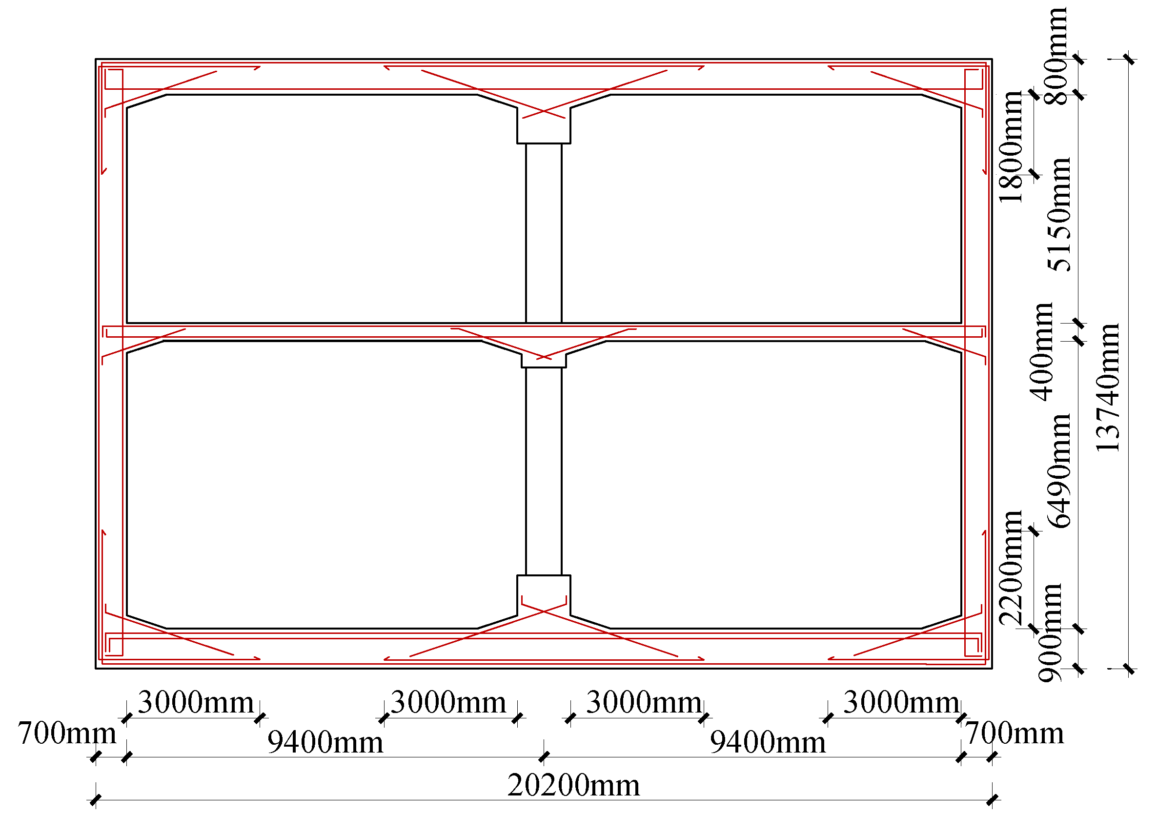
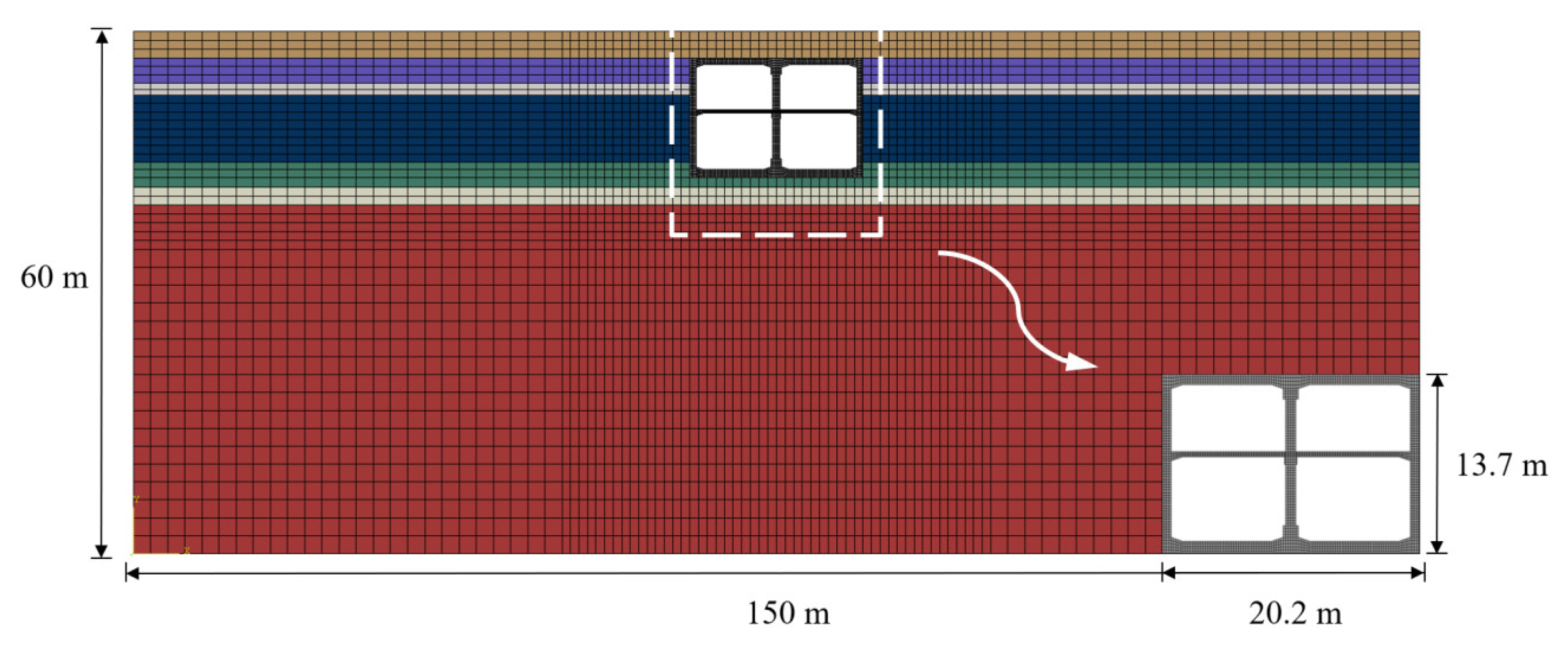
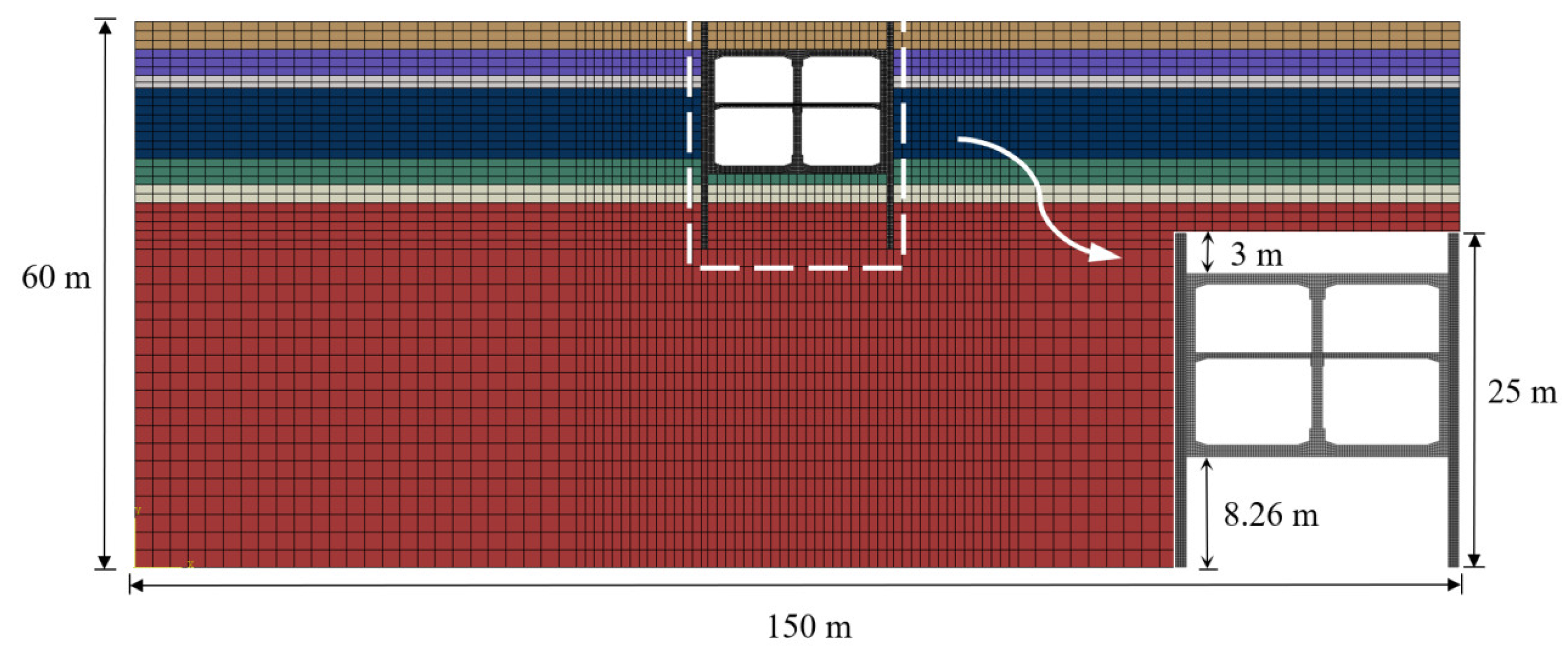
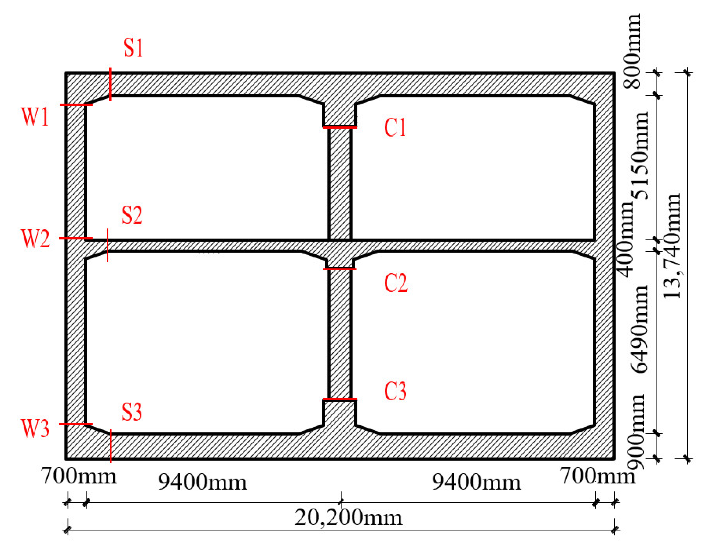
The dynamic time history analysis for the diaphragm wall–segmental isolation layer–station structure system is carried out to study the shock absorption effect of the segmental isolation layer on the subway station. The impact of different segmental forms, material stiffness and thickness of the isolation layer on the seismic reduction of the station structure is discussed.

2.1.1. Model

A two-story and two-span subway station is selected with a cross-section width of 20.20 m and a height of 13.74 m. The thickness of top plate, middle plate, bottom plate and side wall of the station are 0.8 m, 0.4 m, 0.9 m and 0.7 m, respectively. The size of the central column is 0.8 m × 1.0 m. The longitudinal spacing of the middle column is 9 m. In the two-dimensional (2D) finite element analysis, the elastic modulus of the central column is reduced. The central column is equivalent to a continuous longitudinal wall with a thickness of 0.8 m. The thickness of soil layer on the station is 3 m. The buried depth of the bottom plate is 16.74 m. The embedded depth of the diaphragm wall is 25 m and the thickness is 0.8 m. The C35 concrete is used for the station beams, slabs, side walls and diaphragm walls, respectively. The C50 concrete is used for the central column. HRB400 and HPB300 rebar are used for the reinforcement. The cross section and reinforcement arrangement of the main structure are displayed in Figure 2.
A 2D finite element model is established by using ABAQUS software, as shown in Figure 3, Figure 4, Figure 5 and Figure 6. The width and height of the site model are taken as 150 m and 60 m. The concrete plastic damage constitutive model is selected for the main structure of the station and the concrete of the diaphragm wall. The ideal elasto-plastic constitutive model is selected for the reinforcement. The truss element is used for discretization. The reinforcement is embedded into the concrete in the way of built-in area. The bond and slip between the concrete and the reinforcement are ignored. The plane strain element of four nodes is adopted for the station structure, diaphragm wall and surrounding soil. In order to meet the accuracy requirements of numerical simulation, the mesh size of the element shall not exceed 1/6~1/8 minimum wavelength and the soil meshes adjacent to the structure are refined. The mesh size of the main structure and the diaphragm wall unit are about 0.2 m. The mesh size of the soil elements varies from 0.7 m to 2 m. The side wall and the diaphragm wall in the model are connected by surface to surface. The normal direction is set as “hard” contact and the tangential direction is set as “penalty” contact. The friction coefficient μ takes 0.55 [4]. Roller boundaries are set on both side boundaries of the whole model. The width of the model is more than seven times the width of the station, so as to eliminate the influence of boundary effect. The fixed boundary is adopted at the bottom of the model. For the same purpose, the station bottom plate is 43.26 m away from the bottom boundary of the model, which is more than three times the height of the station. Figure 5 and Figure 6 show the 2D integral time-domain finite element analysis model of the soil–diaphragm wall–isolation layer structure under the condition of setting the integral isolation layer and setting the segmented isolation layer, respectively.
The setting conditions for different working condition in the analysis are listed in Table 1. When considering the influence of different section forms, the thickness of the integral isolation layer and segmented isolation layer is 1 m and the height is taken as 13.74 m. The C35 concrete is used as the rigid isolation layer material in the segmented isolation layer. The ideal elastic material with an elastic modulus of 3.15 MPa and a Poisson’s ratio of 0.2 is used as the flexible isolation layer.
When studying the influence law of the stiffness of the isolation layer materials, the isolation layer materials are in the form of segments. The rigid isolation layer materials are made of C35 concrete. The elastic modulus of the flexible isolation layer materials is taken as 3.15 MPa, 31.5 MPa, 315 MPa and 31,500 MPa, respectively (at this time, the materials of the rigid isolation layer and the flexible isolation layer in the segmented isolation layer have the same stiffness). The thickness of the isolation layer is 1 m and the height is taken as 13.74 m.
When studying the influence law of the thickness of the isolation layer, the thickness of the isolation layer is taken as 1 m, 0.5 m and 0.2 m, respectively. The isolation layer is in the form of segments and the height is taken as 13.74 m. The rigid isolation layer is made of C35 concrete. The elastic modulus of the flexible isolation layer is taken as 3.15 MPa.

2.1.2. Site Conditions

The nonlinear viscoelastic model of the Devidenkov skeleton curve modified by Martin et al. [22] is selected. The site soil material parameters are listed in Table 2, and the relevant fitting parameters are shown in Table 3. The mathematical expression of the model is written as follows:
τ ( γ ) = G γ = G max γ [ 1 H ( γ ) ] H ( γ ) = ( γ / γ 0 ) 2 B 1 + ( γ / γ 0 ) 2 B A
where γ is the shear strain, τ(γ) is the shear stress and Gmax is the maximum shear modulus of soil, the improved γ0 has no clear physical significance and both A and B are fitting parameters related to soil.

2.1.3. Ground Motion Input

The Kobe ground motion is input at the bottom of the model. The peak acceleration of the seismic wave is adjusted to 0.15 g, with a time interval of 0.01 s and a duration of 30 s. The original acceleration time history is shown in Figure 7.

2.2. The Effect of Isolation Layer

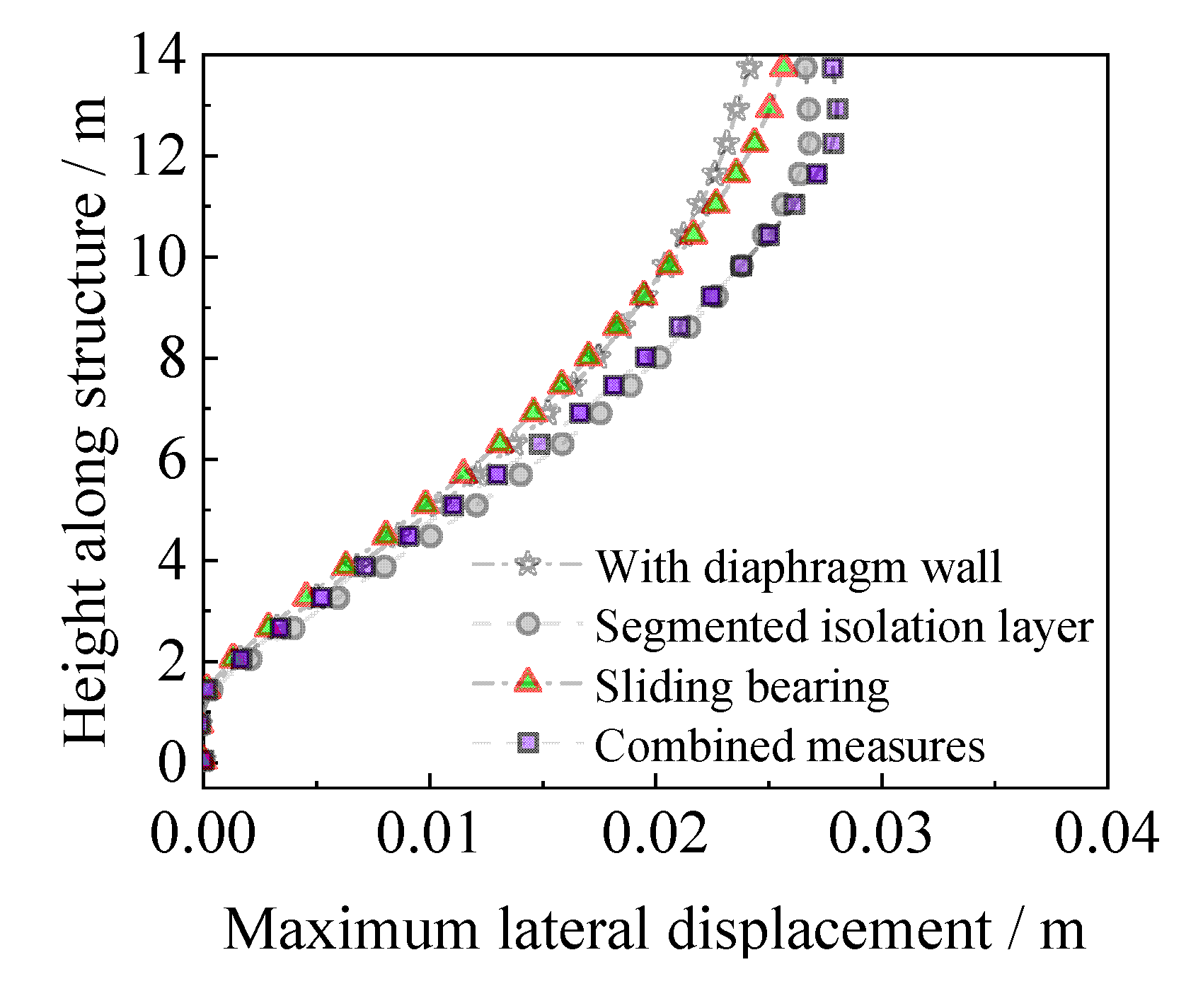
2.2.1. Deformation Analysis of Main Structure

The change curve of the structural lateral displacement along the height when the relative displacement between the top and bottom of the structure reaches the peak value is shown in Figure 8a. It can be seen that the structural lateral deformation is obviously affected by the isolation layer segmented form. Compared with the case of only the diaphragm wall, the integral isolation layer obviously amplifies the interstory displacement of the station structure. However, the displacement between floors is slightly enlarged when the segmented isolation layer is used, but the overall lateral displacement curve of the structure is close to that of the case with only the diaphragm wall. This is the main reason why the rigid isolation layer is used to connect the diaphragm wall with the top plate, middle plate and bottom plate.
Figure 8b shows the lateral displacement of structure by setting the segmented isolation layer with different stiffness. It can be seen that the lateral deformation of the structure is obviously affected by the stiffness of the flexible isolation layer material. As the flexible isolation layer changes from soft to hard, the relative displacement between the top and bottom of the structure gradually decreases. When the elastic modulus of the flexible isolation layer is taken as 31,500 MPa, the relative displacement reaches the minimum value. By observing the shape of the curve, it can be found that the lateral deformation curve of the structure has an obvious turning point at the connection between the rigid and flexible isolation layer. The deformation characteristic is less affected by the stiffness change of the flexible isolation layer.
Figure 8c shows the lateral displacement of structure by setting the segmented isolation layer thickness. The lateral deformation of the structure is obviously affected by the thickness of the layer. With the thinning of the layer, the relative displacement between the top and bottom of the structure gradually decreases. When the thickness of the layer is 0.2 m, the relative displacement reaches the minimum. The segmented isolation layer of 0.2 m thick is enlarged by 3.18% compared with the case without the diaphragm wall. Compared with the case with only the diaphragm wall, the segmented isolation layer is enlarged by 1.82%.

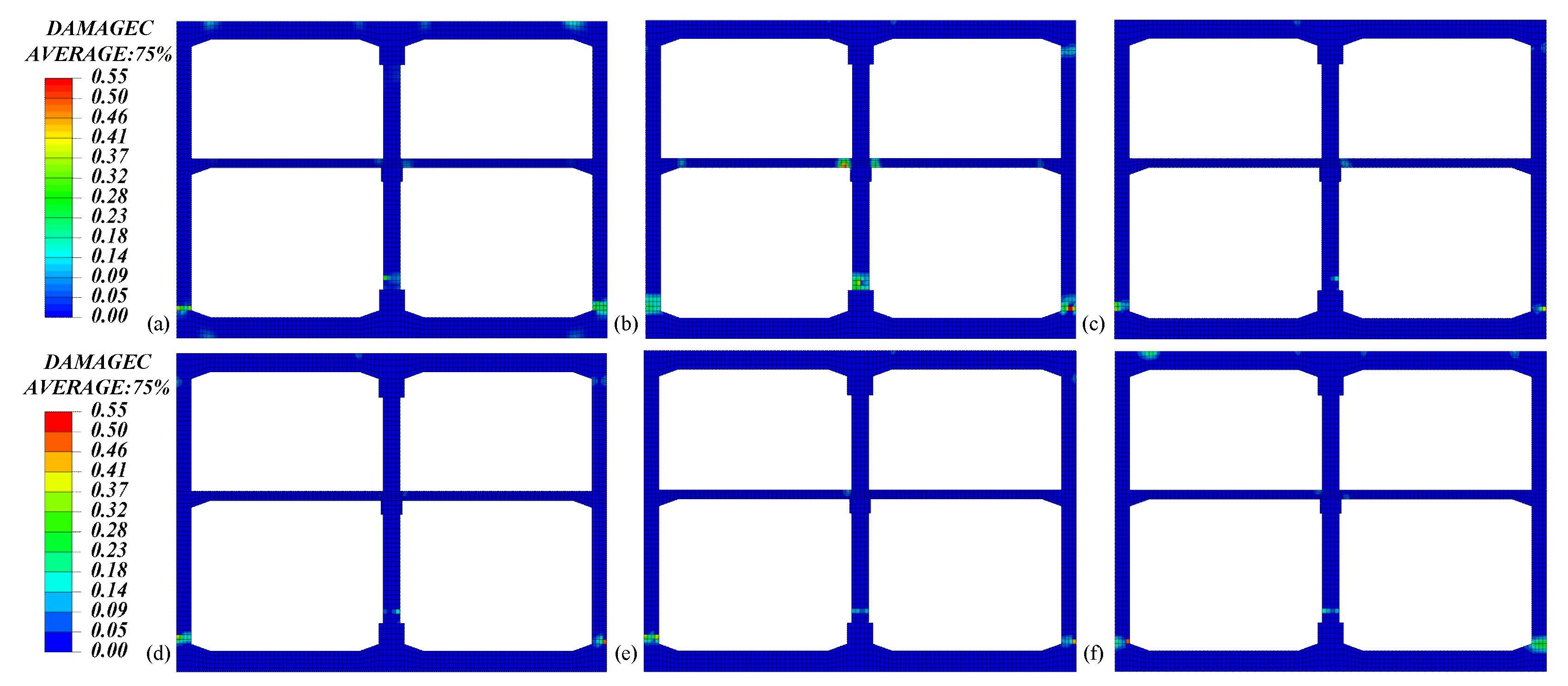
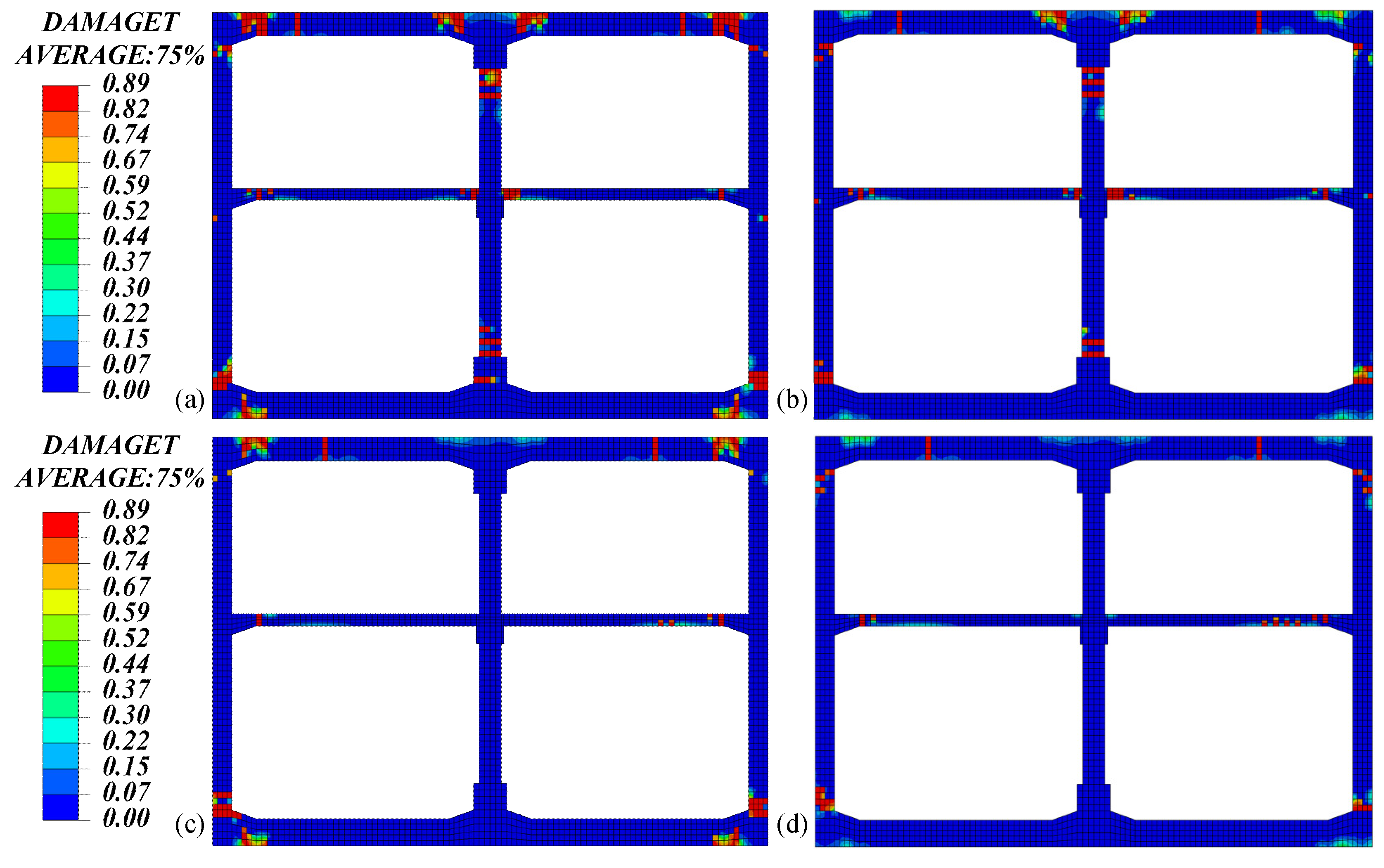
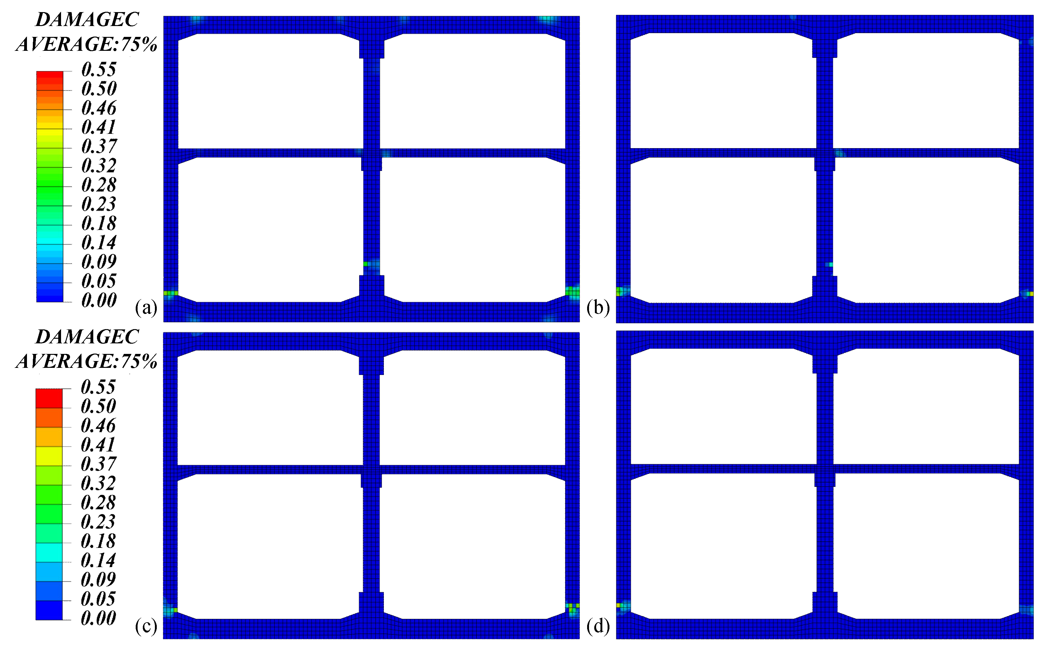
2.2.2. Damage Analysis of the Main Structure

When the relative displacement between the top and bottom of the structure reaches the peak value, the tensile and compressive damage of the station structure using the overall isolation layer and the segmented isolation layer are shown in Figure 9 and Figure 10, respectively. Compared with the case where only the diaphragm wall is set, the integral isolation layer reduces the damage at the junction of the top, bottom and side wall of the structure. At the same time, the integral isolation layer significantly increases the tensile and compressive damage of the side wall and central column of the structure. After the use of segmented isolation layer, on the basis of weakening the damage at the junction of the top, bottom and side walls of the structure, the damage of the side wall and middle column are improved compared with the overall isolation layer. The tensile damage at the joint between the top plate and the central column obviously improves.
With the relative displacement between the top and bottom of the structure reaching the peak, the tension and compression damage of the station structure with a segmented isolation layers of varying thickness is shown in the Figure 11 and Figure 12. Compared with the case of using a 0.5 m thick and 0.2 m thick segmented isolation layer, the use of a 1 m thick segmented isolation layer has a more obvious effect on weakening the damage at the junction of the structure top, bottom plate and side wall and the junction of the structure top plate and central column. As a whole, the thicker the segmented isolation layer is, the better the damping effect of the top plate is.

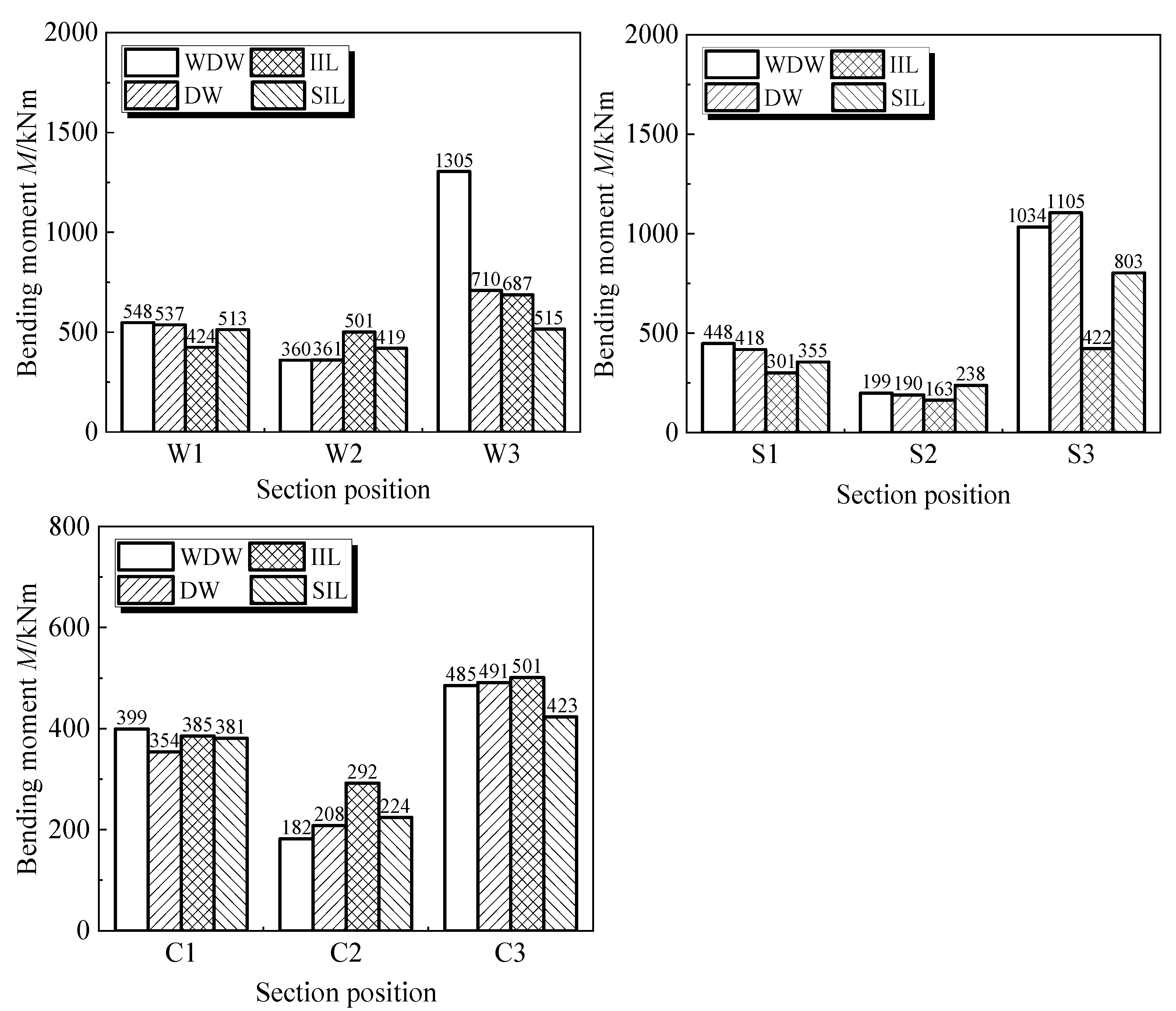
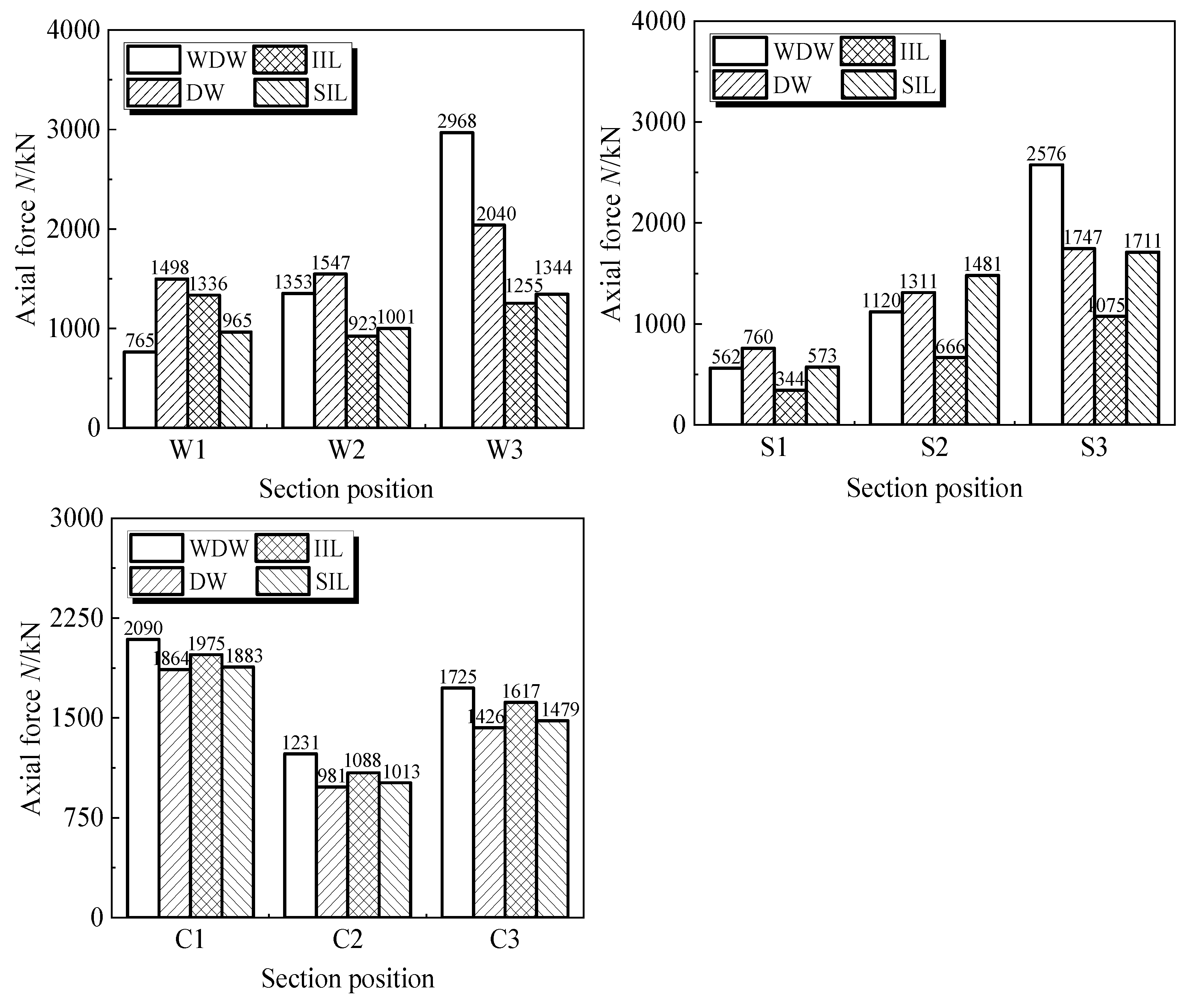
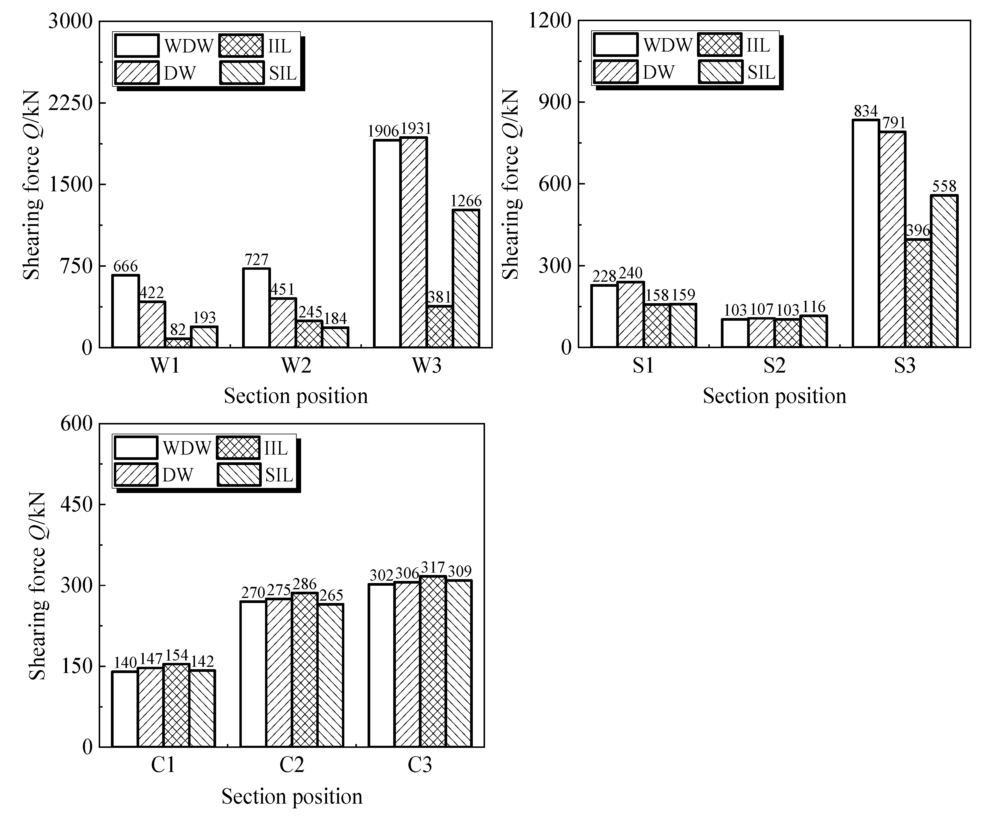
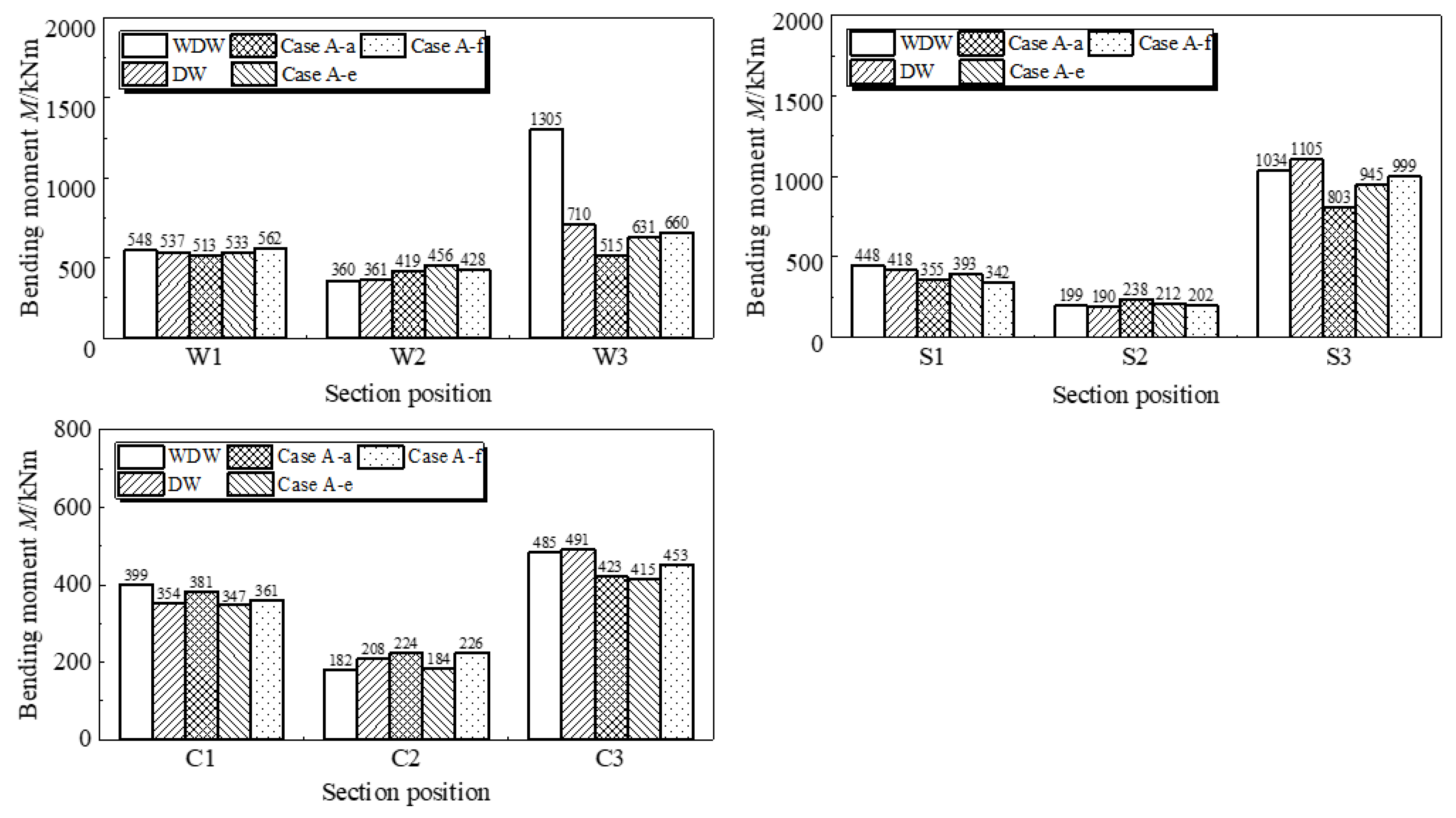
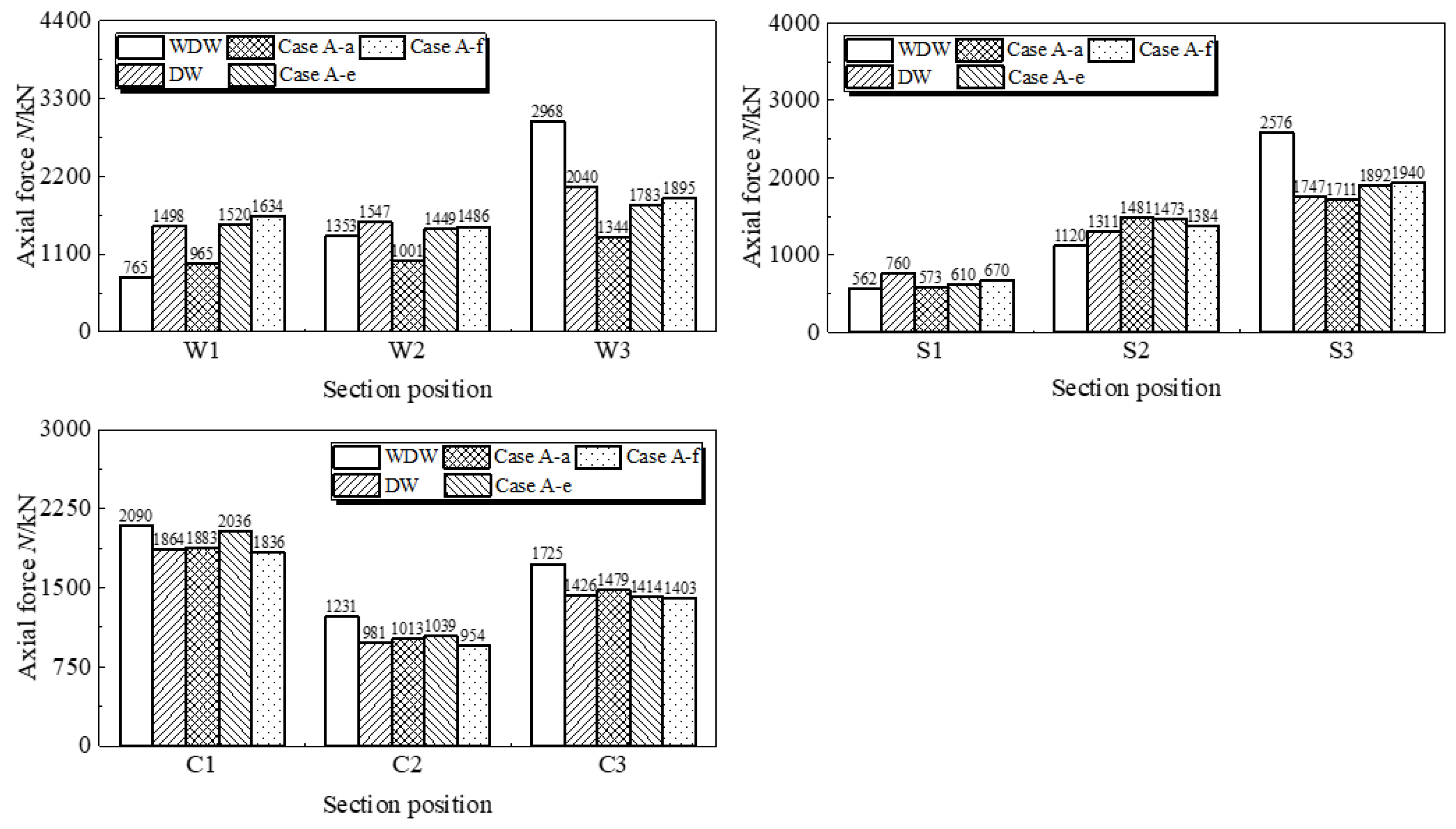
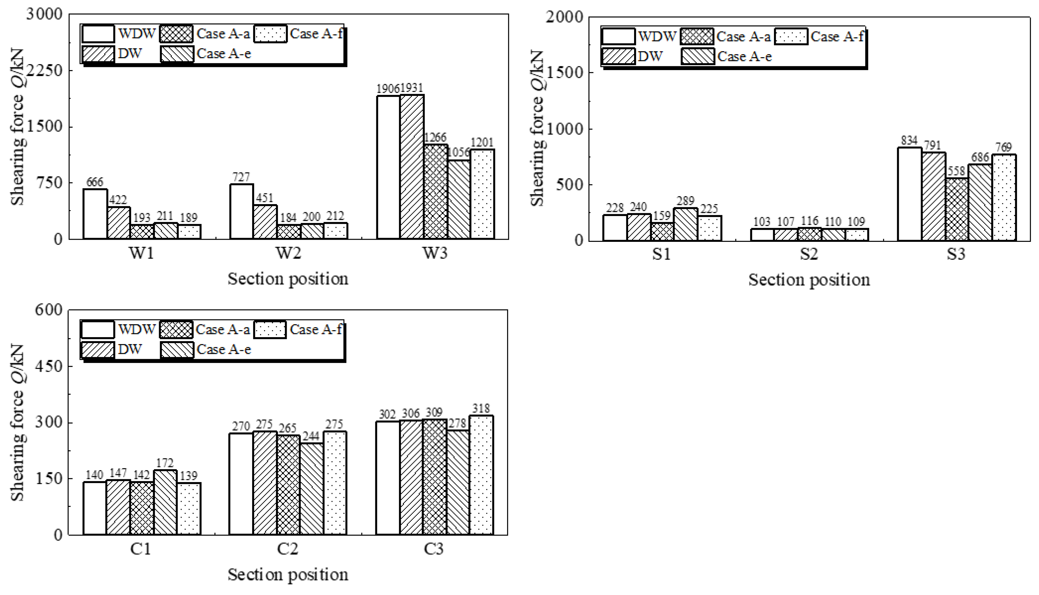
2.2.3. Internal Force Analysis of Key Sections

In order to analyze the internal force response of the station structure, the key parts are selected, as shown in the red line in Figure 13. Among them, the sections of side wall, slab and middle column are represented by letters W, S and C, respectively.
The maximum bending moment, axial force and shear force of the key structural members is studied after the use of the integral isolation layer and the segmented isolation layer. WDW, DW, IIL and SIL represent without diaphragm wall, diaphragm wall, integral isolation layer and segmented isolation layer, as shown in the Figure 14, Figure 15 and Figure 16, respectively. It can be seen that compared with the case of only the diaphragm wall, when the integral isolation layer is used, the internal force at the connection between the side wall, top and bottom plate and the connection between the plate and the side wall of the structure is reduced, but the internal force of the central column is amplified. Compared with the case of only the diaphragm wall, the segmented isolation layer reduces the internal force at the connection between the top and bottom plate and the side wall, indicating that the segmented isolation layer weakens the seismic response of the top and bottom plate. The segmented isolation layer also reduces the internal force of the top middle column and the connection between the side wall and the plate. In addition, the segmented isolation layer has little effect on the internal force of the column in the structure.
Figure 17, Figure 18 and Figure 19 shows the variation of the maximum internal force of the key structural members of the station with different stiffness segmented isolation layers. It can be seen from the Figure 17, Figure 18 and Figure 19 that as the flexible isolation layer changes from hard to soft, the bending moment and shear force at the connection between the top plate, bottom plate and side wall of the structure gradually decrease, which corresponds to the gradual weakening of the damage at the end of the top and bottom plate. The variation law of internal force at other sections is not obvious.
When a segmented isolation layer of varying thickness is used, the maximum internal force of the key structural members of the station can be calculated. In Figure 20, Figure 21 and Figure 22, with the thinning and thickening of the layer, the bending moment and axial force at the connection between the structural side wall and the top and bottom plate and the internal force at the connection between the bottom plate and the side wall gradually decrease, which corresponds to the gradual weakening of the damage at the end of the top and bottom plate. In addition, the bending moment and shear force of the middle column on the ground floor have the trend of decreasing first and then increasing. The variation law of internal force at other sections is not obvious.

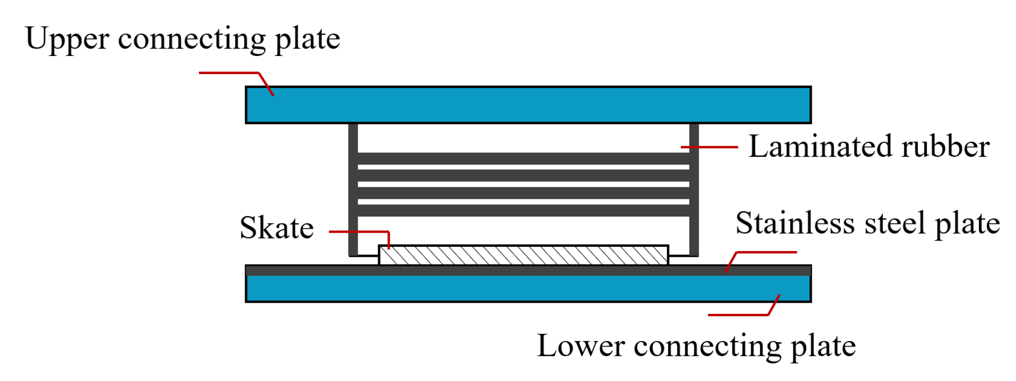
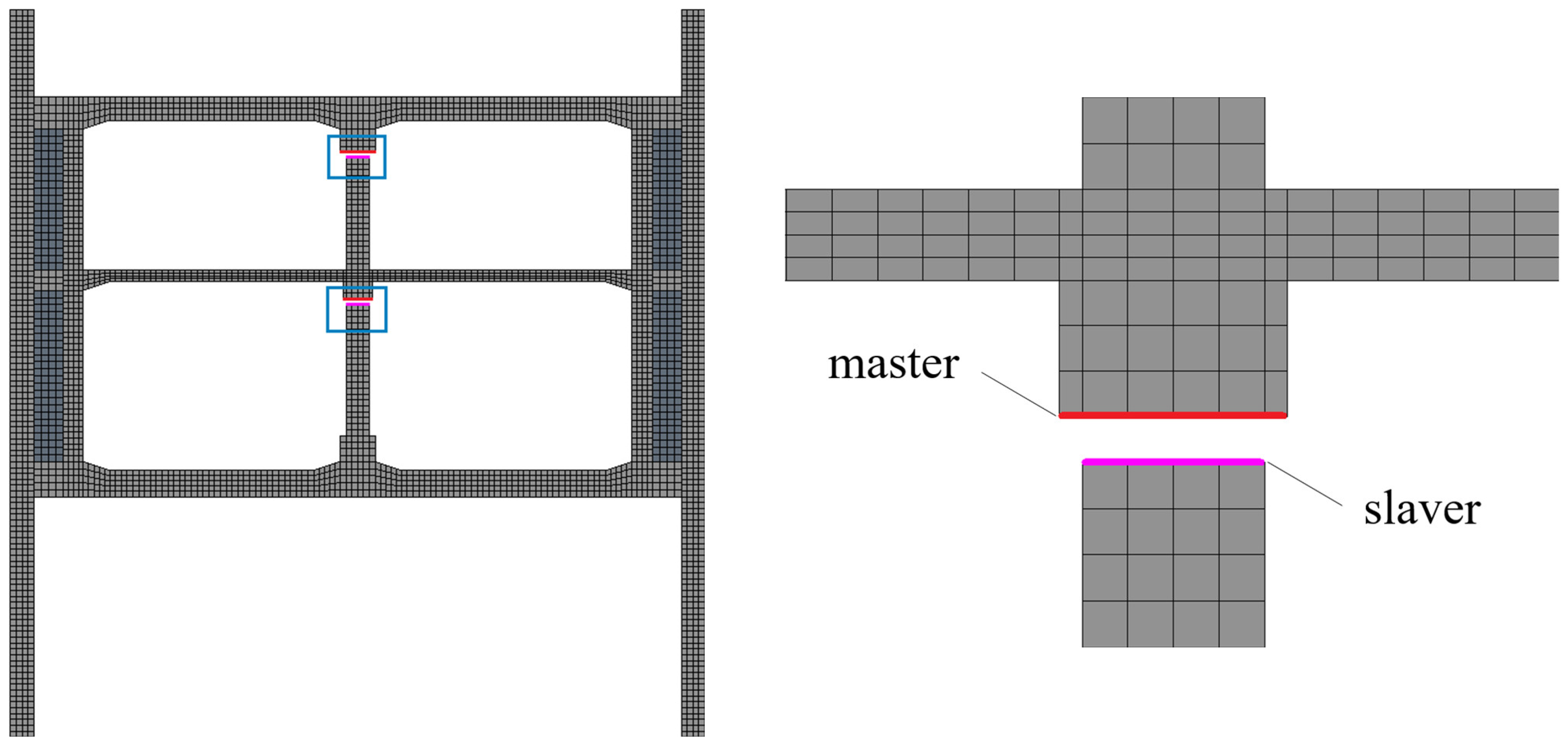
3. Combined Measures of the Sectional Interlayer and Column Top Sliding Support

The isolation layer mainly improves the stress state and damage characteristics of the side wall and plate components, but the seismic response of the central column has not been significantly reduced. In order to improve the overall seismic performance of the structure, the segmented isolation layer and the new bearing of the middle column is combined in this paper. While inserting the segmented isolation layer between the continuous wall and the structure, the sliding bearing damping measures are set at the top of the top and bottom middle columns. The finite element model of the soil–underground structure interaction is established, and the influence of the combined damping measures of segmented isolation layer and new bearing of the middle column on the seismic performance of the underground station structure is analyzed.

3.1. Finite Element Model

The elastic sliding bearing is generally composed of an upper connecting plate, laminated rubber, sliding plate, mirror stainless steel plate, and lower connecting plate. The structure diagram is shown in Figure 23 [23].
In this study, the elastic sliding bearing is set on the top of the central column in the station structure, as shown in Figure 24. In the finite element model, the contact surface between the structural longitudinal beam and the top of the intermediate column is established. The contact connection of surface to surface is set. The friction coefficient of sliding surface is taken as 0.025 [23].

3.2. The Effect of Combined Measures

3.2.1. Deformation Analysis of the Main Structure

Three methods are adopted, namely, the segmented separation layer, the sliding bearing set at the top of the column and the combined measures of the segmented separation layer and the sliding bearing at the top of the column. When the relative displacement between the top and bottom of the structure reaches the peak, the change curve of the lateral displacement along the height of the three schemes is shown in Figure 25. It can be seen that compared with the case with only the diaphragm wall, the combined measures slightly magnify the interstory displacement of the station structure. While the column top sliding support is used alone, the interstory displacement of the structure is slightly reduced. The overall lateral displacement curve is close to the case with only the diaphragm wall.

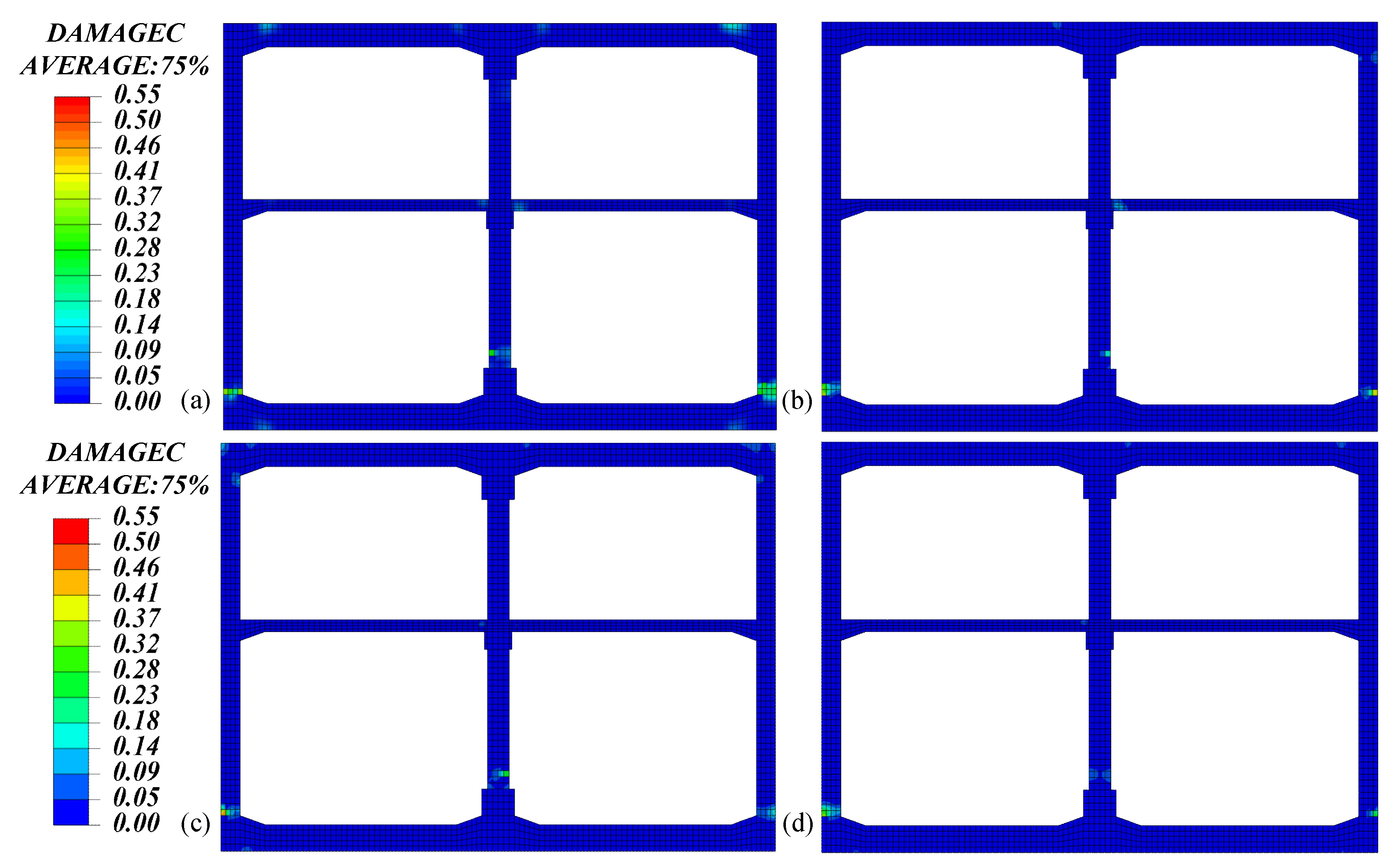
3.2.2. Damage Analysis of the Main Structure

The tensile and compressive damage of the structure is calculated by using the segmented isolation layer, the sliding bearing on the top of the column and the combination of the two measures. Comparing the case where only the diaphragm wall and segmented isolation layer are installed, the addition of sliding bearings and the combined measures significantly reduce damage to the middle column of the structure and improve the connection between the top plate, middle plate and middle column. When the relative displacement between the top and bottom of the structure reaches the peak, the tension and compression damage nephogram of the station structure is shown in Figure 26 and Figure 27, respectively.
Moreover, compared to the installation of sliding bearings alone, the combined measures notably mitigate damage at the joints of the top plate, bottom plate and side wall. Overall, the combination of segmented isolation layer and column top sliding bearing exhibits the most effective damping effect.

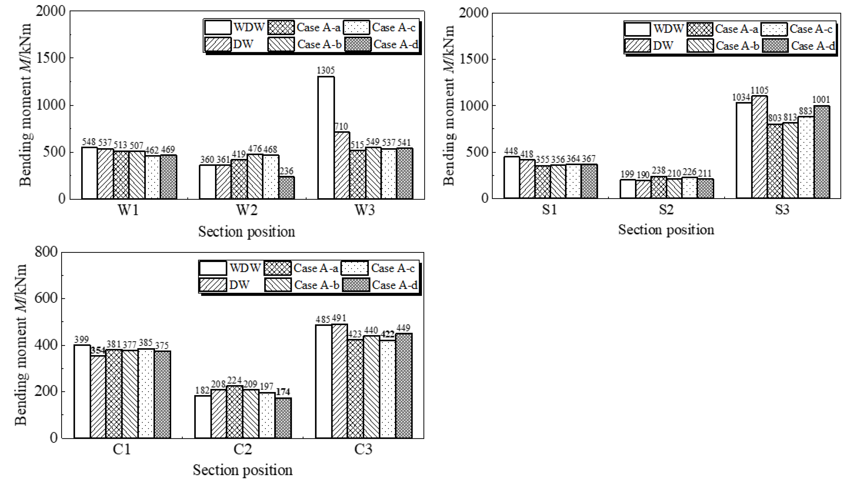
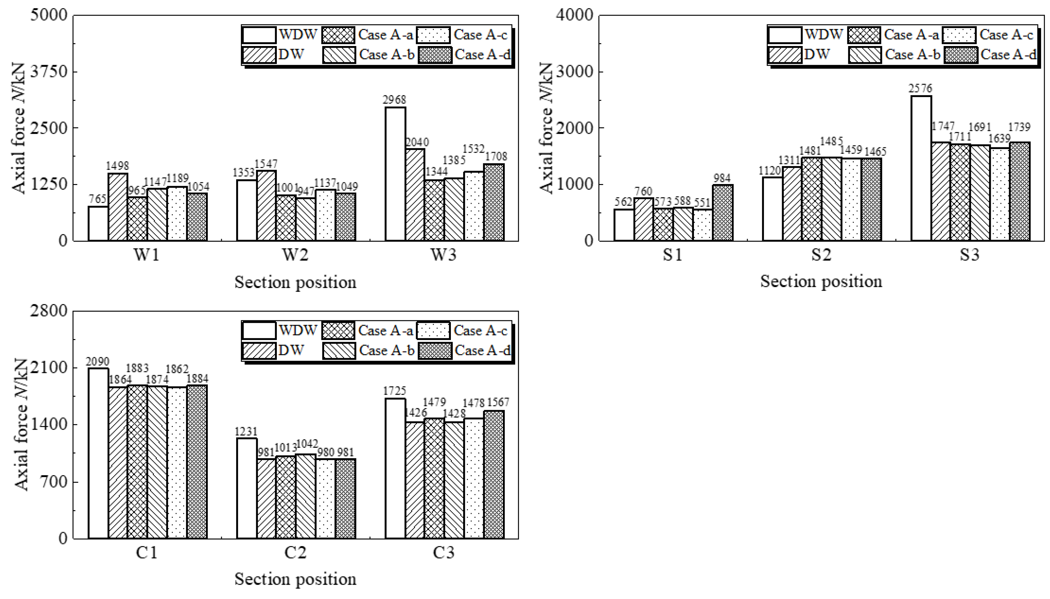
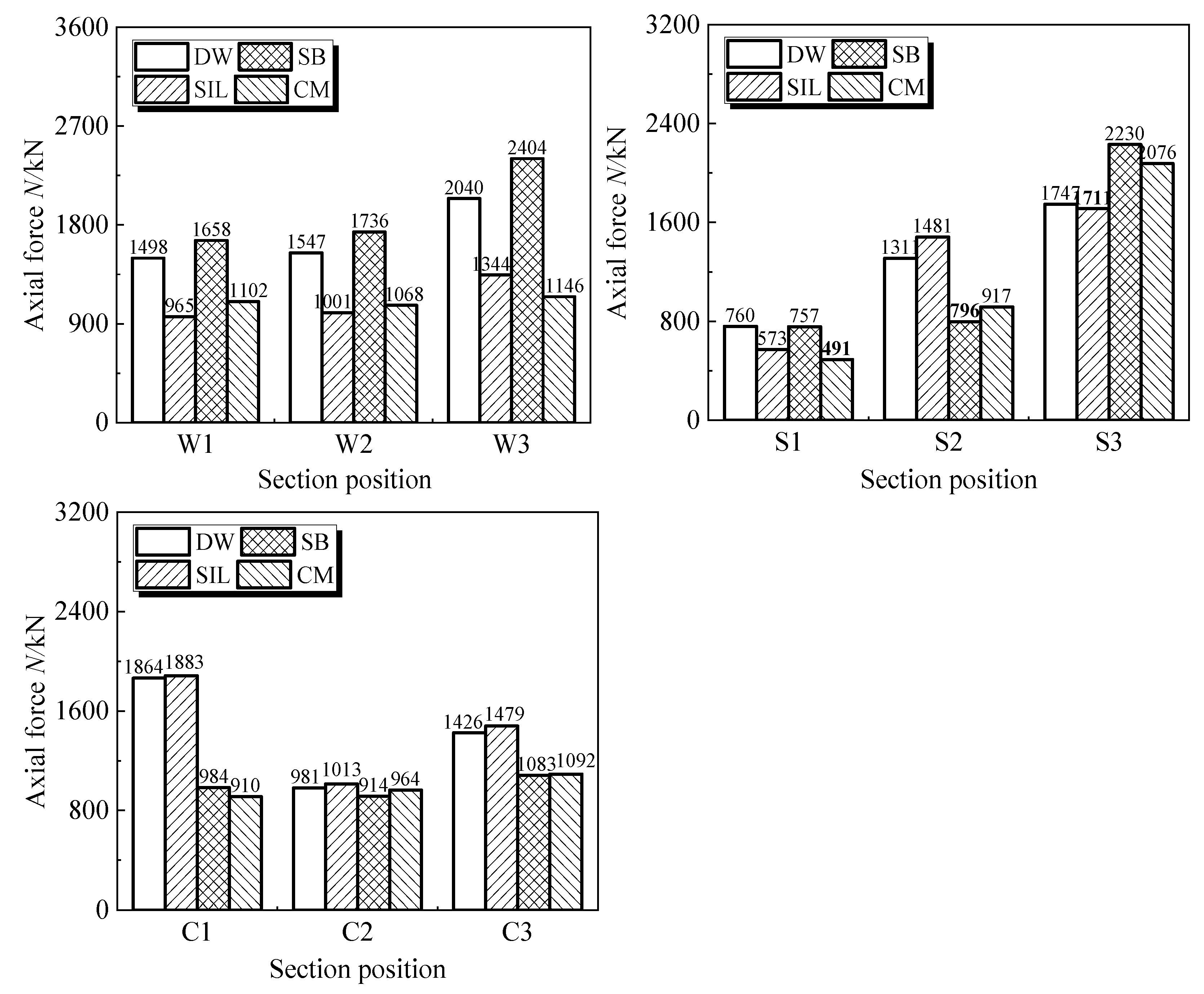
3.2.3. Internal Force Analysis of Key Sections

The changes of the maximum bending moment, axial force and shear force of the key structural members in the station structure are shown in Figure 28, Figure 29 and Figure 30 by adopting the combined measures of the segmented isolation layer, the sliding bearing on the column top and the sliding bearing on the column top of the segmented isolation layer. DW, SIL, SB and CM represent the diaphragm wall, segmented isolation layer, sliding bearing and combined measures in the figures, respectively.
It can be seen from Figure 28, Figure 29 and Figure 30 that, compared with the case of only the diaphragm wall, the sliding bearing generally reduces the internal force at the middle column, side wall and the connection between the middle plate and the side wall of the station structure, but slightly increases the internal force at the connection between the top plate and the side wall. Additionally, when compared to the case with only the diaphragm wall, the combined measures of segmented isolation layer and sliding bearing generally decrease the internal forces on the middle column, side wall and the joints between the top and middle plates and the side wall of the station structure. The combined measures of segmented isolation layer and sliding bearing have a noticeable effect on reducing the internal forces of the main structure compared to the installation of sliding bearings alone.

4. Conclusions

Compared to the case of only the diaphragm wall, the integral isolation layer increases the seismic response of the structural middle column. However, the proposed segmented isolation layer, although slightly increasing the lateral deformation of the structure, effectively reduces the internal forces and damage at the connections between the top and bottom plates and the side walls. Thus, the intended purpose of reducing the seismic response on the key seismic component, namely the top plate, is achieved. For the composite structure, the smaller the stiffness of flexible material, the better the shock absorption effect of the segmented isolation layer. The thicker the thickness of the segmented isolation layer, the better the shock absorption effect of the structural top plate.
The combination of the segmented isolation layer and sliding bearing at the top of the column proves to be an effective measure in reducing the seismic damage to the structural middle column. It significantly mitigates the damage to the top plate and the connections between the middle plate and the middle column of the structure. In the underground structure system, compared with the solely implementing column top sliding bearing, the combined measures of segmented isolation layer and column top sliding bearing significantly reduce the seismic damage at the connection of the structure top plate, bottom plate and side wall. Ultimately, the combined measures of a segmented isolation layer and column top sliding bearing provide the most effective shock absorption effect for the entire structure.

Author Contributions

Conceptualization, Q.Z. and M.Z.; methodology, J.H.; software, Z.G.; validation, Q.Z., M.Z. and Z.G.; formal analysis, J.H.; investigation, J.H.; resources, M.Z.; data curation, J.H.; writing—original draft preparation, Q.Z.; writing—review and editing, Z.G.; visualization, M.Z.; supervision, J.H.; project administration, Q.Z.; funding acquisition, M.Z. All authors have read and agreed to the published version of the manuscript.

Funding

This research was funded by the National Natural Science Foundation of China (52278476), China Postdoctoral Science Foundation (2022M721877) and National Key Research and Development Program (2022YFC3003603 and 2022YFC3004304), which are gratefully acknowledged.

Institutional Review Board Statement

Not applicable.

Informed Consent Statement

Not applicable.

Data Availability Statement

The relevant data are all included in the paper.

Conflicts of Interest

The authors declare no conflict of interest.

References

  1. Zucca, M.; Valente, M. On the limitations of decoupled approach for the seismic behaviour evaluation of shallow multi-propped underground structures embedded in granular soils. Eng. Struct. 2020, 211, 110497. [Google Scholar] [CrossRef]
  2. Wang, J.N.; Ma, G.W.; Zhuang, H.Y.; Dou, Y.M.; Fu, J.S. Influence of diaphragm wall on seismic responses of large unequal-span subway station in liquefiable soils. Tunn. Undergr. Space Technol. 2019, 91, 102988. [Google Scholar] [CrossRef]
  3. Zhuang, H.Y.; Hu, Z.H.; Wang, X.J.; Chen, G.X. Seismic responses of a large underground structure in liquefied soils by FEM numerical modelling. Bull. Earthq. Eng. 2015, 13, 3645–3668. [Google Scholar] [CrossRef]
  4. Zhuang, H.Y.; Yang, J.; Chen, S.; Fu, J.S.; Chen, G.X. Seismic performance of underground subway station structure considering connection modes and diaphragm wall. Soil Dyn. Earthq. Eng. 2019, 127, 105842. [Google Scholar]
  5. Zhuang, H.Y.; Wang, R.; Shi, P.X.; Chen, G.X. Seismic response and damage analysis of underground structures considering the effect of concrete diaphragm wall. Soil Dyn. Earthq. Eng. 2019, 116, 278–288. [Google Scholar] [CrossRef]
  6. Yu, H.T.; Cai, C.; Yuan, Y.; Jia, M.C. Analytical solutions for Euler-Bernoulli Beam on Pasternak foundation subjected to arbitrary dynamic loads. Int. J. Numer. Anal. Methods Geomech. 2017, 41, 1125–1137. [Google Scholar] [CrossRef]
  7. John, C.; Zahrah, T.F. Aseismic design of underground structures. Tunn. Undergr. Space Technol. 1987, 2, 165–197. [Google Scholar] [CrossRef]
  8. Yu, H.T.; Yuan, Y.; Qiao, Z.Z.; Gu, Y.; Yang, Z.H.; Li, X.D. Seismic analysis of a long tunnel based on multi-scale method. Eng. Struct. 2013, 49, 572–587. [Google Scholar] [CrossRef]
  9. Li, P.; Song, E.X. Three-dimensional numerical analysis for the longitudinal seismic response of tunnels under an asynchronous wave input. Comput. Geotech. 2015, 63, 229–243. [Google Scholar] [CrossRef]
  10. Fabozzi, S.; Bilotta, E.; Yu, H.T.; Yuan, Y. Effects of the asynchronism of ground motion on the longitudinal behaviour of a circular tunnel. Tunn. Undergr. Space Technol. 2018, 82, 529–541. [Google Scholar] [CrossRef]
  11. Huang, J.Q.; Du, X.L.; Jin, L.; Zhao, M. Impact of incident angles of P waves on the dynamic responses of long lined tunnels. Earthq. Eng. Struct. Dyn. 2016, 45, 2435–2454. [Google Scholar] [CrossRef]
  12. Gao, Z.D.; Zhao, M.; Huang, J.Q.; Du, X.L. Three-dimensional nonlinear seismic response analysis of subway station crossing longitudinally inhomogeneous geology under obliquely incident P waves. Eng. Geol. 2021, 293, 106341. [Google Scholar] [CrossRef]
  13. Chen, J.; Shi, X.; Li, J. Shaking table test of utility tunnel under non-uniform earthquake wave excitation. Soil Dyn. Earthq. Eng. 2010, 30, 1400–1416. [Google Scholar] [CrossRef]
  14. Chen, Z.Y.; Chen, W.; Bian, G.Q. Seismic performance upgrading for underground structures by introducing shear panel dampers. Adv. Struct. Eng. 2014, 17, 1343–1357. [Google Scholar] [CrossRef]
  15. Chen, Z.Y.; Zhao, H.; Lou, M.L. Seismic performance and optimal design of framed underground structures with lead-rubber bearings. Struct. Eng. Mech. 2016, 58, 259–276. [Google Scholar] [CrossRef]
  16. Chen, Z.Y.; Zhou, Y. Seismic performance of framed underground structures with self-centering energy-dissipation column base. Adv. Struct. Eng. 2019, 22, 2809–2822. [Google Scholar] [CrossRef]
  17. Ma, C.; Lu, D.C.; Du, X.L. Seismic performance upgrading for underground structures by introducing sliding isolation bearings. Tunn. Undergr. Space Technol. 2018, 74, 1–9. [Google Scholar] [CrossRef]
  18. Xu, Z.G.; Du, X.L.; Xu, C.S.; Han, R.B. Numerical analyses of seismic performance of underground and aboveground structures with friction pendulum bearings. Soil Dyn. Earthq. Eng. 2020, 130, 105967. [Google Scholar] [CrossRef]
  19. Liu, D.; Du, X.L.; El Naggar, H.M.; Xu, C.S.; Chen, Q. Seismic mitigation performance analysis of underground subway station with arc grooved roller bearings. Soil Dyn. Earthq. Eng. 2022, 153, 107082. [Google Scholar] [CrossRef]
  20. Hasheminejad, S.M.; Miri, A.K. Seismic isolation effect of lined circular tunnels with damping treatments. Earthq. Eng. Eng. Vib. 2008, 7, 305–319. [Google Scholar] [CrossRef]
  21. Kiryu, S.; Murono, Y.; Morikawa, H. Seismic response of a cut-and-cover tunnel isolated by polymer material. Earthq. Eng. Struct. Dyn. 2012, 41, 2043–2057. [Google Scholar] [CrossRef]
  22. Martin, P.P.; Seed, H.B. One-dimensional dynamic ground response analyses. J. Geotech. Eng. Div. 1982, 108, 935–952. [Google Scholar] [CrossRef]
  23. Zhuang, H.Y.; Fu, J.S.; Chen, S.; Zhao, C.; Zhao, K.; Chen, G. Seismic performance analysis of subway underground station structures with sliding bearings installed at the top of columns. Tunn. Undergr. Eng. Disaster Prev. Control. 2019, 1, 57–67. (In Chinese) [Google Scholar]
Figure 1. Structural system model of diaphragm wall–segmented isolation layer–subway station. (a) System diagram of diaphragm wall–segmented isolation layer–station structure. (b) Combination diagram of the rigid isolation layer, flexible isolation layer and diaphragm wall and (c) its profile.
Applsci 13 06910 g001
Figure 2. A cross section of the subway station.
Applsci 13 06910 g002
Figure 3. Finite element model without a diaphragm wall.
Applsci 13 06910 g003
Figure 4. Finite element model with a diaphragm wall.
Applsci 13 06910 g004
Figure 5. Finite element model with an integral isolation layer.
Applsci 13 06910 g005
Figure 6. Finite element model with a segmented isolation layer.
Applsci 13 06910 g006
Figure 7. Input seismic records.
Applsci 13 06910 g007
Figure 8. Variation curve of the lateral displacement along the structure height (a) different structural forms (b) the segmented isolation layer with different stiffness (c) the segmented isolation layer different thickness.
Applsci 13 06910 g008
Figure 9. Cloud diagram of the structural tensile damage: (a) diaphragm wall; (b) integral isolation layer; (c) case a; (d) case b; (e) case c; (f) case d.
Applsci 13 06910 g009
Figure 10. Cloud diagram of the structural compression damage: (a) diaphragm wall; (b) integral isolation layer; (c) case a; (d) case b; (e) case c; (f) case d.
Applsci 13 06910 g010
Figure 11. Cloud diagram of the structural tensile damage: (a) diaphragm wall; (b) case a; (c) case e; (d) case f.
Applsci 13 06910 g011
Figure 12. Cloud diagram of the structural compression damage: (a) diaphragm wall; (b) case a; (c) case e; (d) case f.
Applsci 13 06910 g012
Figure 13. Schematic diagram of the section position.
Applsci 13 06910 g013
Figure 14. Bending moment of the key section of the structure.
Applsci 13 06910 g014
Figure 15. Axial force of the key section of the structure.
Applsci 13 06910 g015
Figure 16. Shearing force of the key section of the structure.
Applsci 13 06910 g016
Figure 17. Bending moment of the key section of the structure.
Applsci 13 06910 g017
Figure 18. Axial force of the key section of the structure.
Applsci 13 06910 g018
Figure 19. Shearing force of the key section of the structure.
Applsci 13 06910 g019
Figure 20. Bending moment of the key section of the structure.
Applsci 13 06910 g020
Figure 21. Axial force of the key section of the structure.
Applsci 13 06910 g021
Figure 22. Shearing force of the key section of the structure.
Applsci 13 06910 g022
Figure 23. The structure diagram of the elastic sliding bearing.
Applsci 13 06910 g023
Figure 24. Finite element model of the elastic sliding bearing.
Applsci 13 06910 g024
Figure 25. Variation curve of the lateral displacement along the structure height.
Applsci 13 06910 g025
Figure 26. Cloud diagram of the tensile damage of the structure: (a) the diaphragm wall; (b) the segmented separation layer; (c) the sliding bearing; (d) the combined measures.
Applsci 13 06910 g026
Figure 27. Cloud diagram of the compression damage of the structure: (a) the diaphragm wall; (b) the segmented separation layer; (c) the sliding bearing; (d) the combined measures.
Applsci 13 06910 g027
Figure 28. Bending moment M of the key section of the structure.
Applsci 13 06910 g028
Figure 29. Axial force N of the key section of the structure.
Applsci 13 06910 g029
Figure 30. Shearing force Q of the key section of the structure.
Applsci 13 06910 g030
Table 1. Stiffness and thickness of isolation layer.
Form of isolation layerStiffness and Thickness of Isolation Layer
abcdef
EC35/10,000EC35/1000EC35/100EC35EC35/10,000
3.15 MPa
3.15 MPa31.5 MPa315 MPa31,500 MPa
Thickness
(1.0 m)
Thickness (0.5 m)Thickness (0.2 m)
Segmented isolation layerApplsci 13 06910 i001
Table 2. Soil materials of the engineering site profile.
Layer NumberSoil StratumUnit Weight (kN/m3)Elastic Modulus (MPa)POISSON’S
Ratio
Shear Wave Velocity (m/s)
1Miscellaneous fill17.570.770.35193
2Silty clay19.4117.140.36247
3Pebbles21.2177.610.23298
4Medium coarse sand20.3149.450.29279
5Pebbly silty clay19.7169.70.31295
6Silty clay19.4183.790.36307
7Clayey silt20.9208.510.33327
Table 3. The values of the Davidenkov model parameters.
Soil StratumABγ0 (×104)
Miscellaneous fill1.20.41.69
Silty clay1.20.475.8
Pebbles1.250.318.99
Sand1.150.335.36
Silt1.050.495.4
Disclaimer/Publisher’s Note: The statements, opinions and data contained in all publications are solely those of the individual author(s) and contributor(s) and not of MDPI and/or the editor(s). MDPI and/or the editor(s) disclaim responsibility for any injury to people or property resulting from any ideas, methods, instructions or products referred to in the content.

