Article

Application of the Kinematic Assessment of Multi-Faced Slopes Using Stereographic Projection: The Case Study of a Planar Failure on the Spondylus Coast, Ecuador

by
Cesar Patricio Borja Bernal
1,2,* and
Luis Jordá Bordehore
3
1
ETSI Minas y Energía, Universidad Politécnica de Madrid, Calle de Ríos Rosas, 21, 28003 Madrid, Spain
2
Facultad de Ciencias Naturales, Universidad de Guayaquil, Av. Raúl Gómez Lince s/n y Av. Juan Tanca Marengo, Guayaquil 090601, Ecuador
3
Departamento de Ingeniería y Morfología del Terreno, Universidad Politécnica de Madrid, 28040 Madrid, Spain
*
Author to whom correspondence should be addressed.
Appl. Sci. 2023, 13(14), 8245; https://doi.org/10.3390/app13148245
Submission received: 14 May 2023 / Revised: 3 July 2023 / Accepted: 8 July 2023 / Published: 16 July 2023
(This article belongs to the Special Issue Advances in Sustainable Geotechnical Engineering)

Abstract

:
This manuscript presents a relevant practical application of the stability analysis of multi-face slopes that uses the concept of the restricted daylight envelope in multi-faced slopes (MFS). The methodology was applied to the back analysis of a case study of a failed slope in mudstones and sandstones on the Spondylus coast in Ecuador. The instabilities analyzed included several rock cliffs with dihedral rock faces in mudstones. It is interesting to analyze the failure mechanism of these natural coastal slopes because, on the Spondylus coast, several hotels and tourist spots are located near the upper parts of some similar regions. The stereographic projection methodology can simulate complex geometries and simplify the analysis.

1. Introduction and Scope

Stereographic projection methods have been widely extended to slope analysis in jointed rocks and the possible failure modes [1] since the first studies by Markland in 1972 [2] and John in 1968, 1972 [3,4]. Although 40 years have passed since these works were published and powerful computer tools have been developed, stereographic projection in block kinematic analysis is still current. Stereographic projection allows a quick view of the possible failure modes of the slope, such as planar, wedge, and toppling, and reduces the analyzed elements to one dimension: planes to curves, straight lines to points, etc. This research focuses on an analysis of the three-dimensional geometry of slopes with several faces, which has not been much studied in the literature [1].
Most kinematic analyses of rock slopes only consider the fact that the slope face has a constant strike (single-faced SFS) [5]. In 2002, Yoon et al. [5] introduced the concept of and kinematic criterion for multifaceted (also known as multi-faced) slope MFS failure in an intuitive and highly effective way by focusing on the analysis of planes and vectors, not on the pole criterion, which is the most common method [1].
In stereographic projection, the sliding envelope of a multi faced slope (MFS) is the union of single-face envelopes formed on the surface of the slope” (Yoon et al. [5]). Jordá-Bordehore et al. [1] proposed to combine the methodology for multi-faced slopes [5] with the most usual approach for the kinematic assessment of single-faced slope daylight envelope and pole analysis [6,7].
The aim of this research is to show a real case of a failed slope for which the stability assessment can only be explained using a methodology that unifies the traditional criteria for rock–slope analysis based on poles [6,7,8,9] with the conclusions of the work of Yoon et al. [5] for MFS, where the criteria for instability were defined using the representation of the poles of the plane approach. The unstable sector in stereographic projection is defined using poles and daylight envelopes [1] instead of planes [5]. The conventional kinematic analysis using constant-strike slopes cannot explain or assess this case. The suggested methodology for the back analysis is effective in explaining the mechanism of planar failure of real slopes, for example, the slate rocks on the Manta coast of Ecuador, and can be extrapolated to other slopes on the Spondylus coast, many of which are typical situations of multi-faced slopes (MFS). The coast of Ecuador, like other coasts with outcrops of marked stratification (Flysch de Zumaia in Spain), presents inlets and outlets, the analysis of which can be approached with the MFS methodology that we propose in this work. There are few studies on the kinematic stability of rocky slopes in Ecuador [10,11,12]. This work reinforces the database and the methodology proposed by Yoon et al. [5] for the Andean zone.
The stability of rock slopes in superficial situations in relatively competent rock masses is usually controlled by the equilibrium of the blocks that form them. This equilibrium is normally studied using kinematic assessment methods that only consider the friction of the most relevant joints and their orientation with respect to the slope. The main contribution and objective of this study is to apply the aforementioned approach to a real slope and verify its effectiveness. It is important to note that this is the first application of this methodology in the Andes, a mountain range with complex slope stability problems, many of which are difficult to model. This study demonstrates that this methodology can be an effective stability methodology.

2. Materials and Methods

The study site is a representative area of the type of failure to be analyzed. Along the coast of Ecuador, in such places as Montañita, Olón, and Ayangue, we find coastal cliffs with stability problems linked to the erosion of the waves and tides at the foot of the cliffs. To adequately analyze the failure mechanism, it is necessary to understand that many landslides are produced through stratification with tensile cracks in vertical slopes, but that the classic models do not fit reality well enough because they consider the slope in the form of a two-dimensional section. This presents a real problem in three dimensions. Conducting MFS slope studies using 3D models sometimes requires computer programs that are not yet accessible to many researchers. The methodology proposed in this work is accessible since it utilizes stereographic projection and reduces the problem to one less dimension. To show the effectiveness of the methodology, we have chosen a test site where the typology is easily identified and represents the difficult approach of Yoon et al. [5] in a very didactic way.
The analysis of interactions between discontinuity planes and slopes is extremely complex to solve using 3D models and isometric projection but is considerably simplified with stereographic projection [1]. We refer the reader to the bibliography for information on stereographic and kinematic assessments of rock slopes, especially using the MFS approach as detailed in Yoon et al. [5] and Jorda et al. [1]. The main idea of the methodology is to use the usual criteria in kinematic analysis for locating poles or planes in some areas of the stereogram that meet the instability conditions. Any pole or crossing of planes that fall in this zone implies kinematic instability between these fractures and the slope. What the MFS methodology does is expand the area known as the “restricted daylight envelope” by considering the slope not as a single plane but as a curved surface that can be simplified as an envelope that spans from one tangent plane to another passing through the tip or “nose” of the concave slope.
The back analysis methodology has been applied in the following way: the model must be equivalent to reality, and when a slope has failed, the model must indicate a safety factor ≤ 1. Normally, we assign joint strength parameters according to various approaches, whether empirical, laboratory, or a combination of both. In this case, we have reconstructed what slopes and detached blocks looked like in their initial situation before the failure. If the analysis or calculation indicates a safety factor greater than unity (or the stable zone of the stereogram), then that means that our calculation is not realistic, and we therefore have to modify the resistance parameters of cohesion or friction until the result comes out to a safety factor of 1, or within the limit of the unstable zone of the stereogram.
The discontinuity friction angle is necessary to draw the friction circle; indeed, it is required in all kinematic analyses via stereographic projection. Friction (φ) is obtained from the Barton–Bandis failure criterion and onsite mapping [13,14,15].

3. Study Site

The study site is on the “Spondylus” coast of Ecuador (Figure 1), characterized by detritic sedimentary formations: siltstones, sandstones, and volcanosedimentary units. The cliffs in these materials show degradation processes, instability, and failures. The typical cliff failures at the study sites are summarized in Figure 2. The failed slope that we analyzed is located at a site named Punta Barbasquillo in the coastal city of Manta. It is a corner formed by a two-faced slope, and it shows a combination of planar sliding and toppling failure.
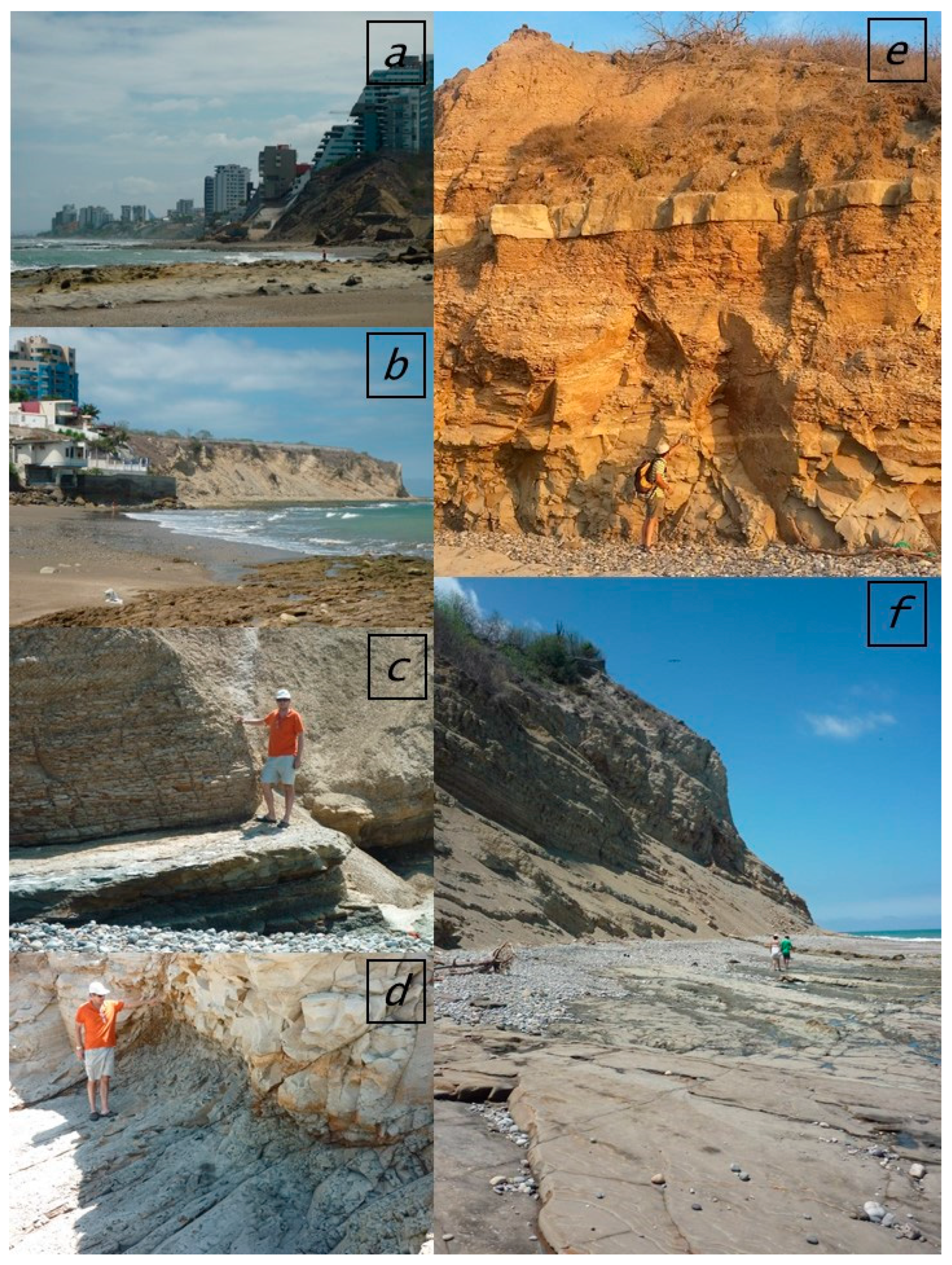
Figure 2a shows Punta Barbasquillo, vertical slopes, and dipping mudstone strata between 25 and 40°. Figure 2b,d are located on Piedra Larga Beach, where there is shallow-dipping stratification and cliffs with medium-dipping slopes with many circular failures. Playa Murciélago (bat) beach (Figure 2c) is in a part of Manta’s coast where many hotel constructions and foundations are located over the unstable cliffs but far enough from the scarp limit; in some cases, reinforcement of the cliff has been accomplished. We note the alternation of mudstones and more compact siltstones affected by normal faults in Figure 2e and the difference in resistance between the cliff and the beach (Figure 2f).

4. Results

4.1. Observational Results

The study area is located at Barbasquillo Cape (Manta, Ecuador), which is a cliff with inlets and outlets parallel to the coastThere are usually two or more vertical joints as well as a sub-horizontal stratification (S0) that is usually the sliding surface of planar failures. There are also many toppling failures due to vertical normal faults (Figure 2 and Figure 3). Some tension cracks are “new”, while others have developed following existing normal faults.
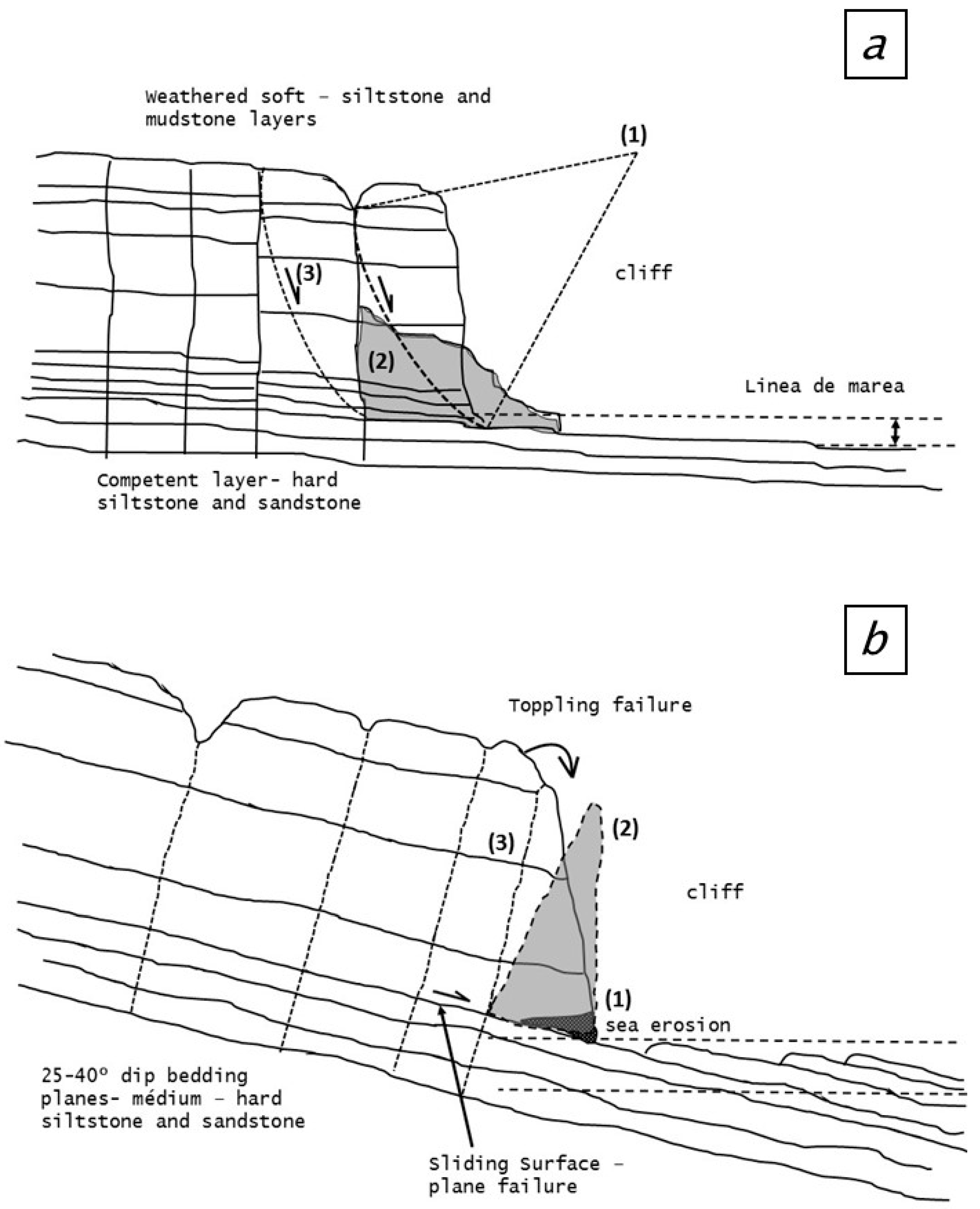
Figure 3a shows a typical failure mode in the cliffs of Piedra Larga Beach near Barbasquillo Cape. There are often circular failures through the rock mass, beginning in tension cracks (previous faults). These circular failures through the rock mass typically occur when the rock strength is very low, and they are not usual when blocks are formed in competent rock massifs. The tide line can undermine the toe of these cliffs, but it is not common. More often, the low tide exposes an extensive rocky platform of competent rock, as in Figure 2f. The failed rock mass is easily eroded, and in a short time, it is disintegrated by the action of the waves and tides (Figure 3a(2)). The instabilities continue inland in an iterative process, and the cliffs gradually lose slices (Figure 3a(3)).
This process of the unraveling of the slabs and the collapse of the cliff is something normal and habitual on the Spondylus Coast of Ecuador. The key point is to interpret how far it can progress in a determined period so that it does not affect infrastructure and houses located in the upper part of the coastline. The presence of tensile cracks associated with vertical structural domains is one of the most important mechanisms controlling the progression and stability of the cliff.
Figure 3b shows schematically the most typical failure mode in the Barbasquillo Cape area and Murcielago (bats) Beach. The failure process in those locations is a combination of planar sliding and toppling. The marine erosion of the lower part of the cliff and the detachment of some toe slices collaborate to trigger the cliff failure process. Depending on the case, this can be toppling, sliding, or a combination of both. In the case of stratification dipping more than 35°, the failure process is mainly planar, and vertical joints act as tension cracks (Figure 2b,f). Once the slice is detached (Figure 3b), the remaining cliff face angle is normally 90°, but it can also overhang at 110–120°, with a clear toppling tendency. Figure 3 summarizes the process leading to the failure scheme of Figure 2f.
Figure 2e highlights a normal fault in mudstones and siltstones. These vertical joints and faults collaborate to trigger cliff instabilities depending on the orientation and dip of the rock face. Figure 2b,f show horizontal strata with layers with diverse grades of resistance to weathering.
Figure 2d shows the beginning of the eroding process of a competent but fractured rock mass. These zones, when exposed to the iterative effects of sea waves and tides, form holes on the base part of the cliffs. This can trigger toppling failures and the filling with water and weathering of joints in planar failures. Figure 2c indicates the opposite phenomenon, that is, the lower part of the cliff is more resistant than the upper parts, causing extended horizontal platforms (Figure 2f). The image in Figure 2f is a transition between failure modes of Figure 3a,b where it is possible to notice a clear structural component in the sliding through the dipping stratification S0 to the sea. Over that plane, failure can be of three types, depending on the resistance and weathering of the rock mass of the cliff: (1) planar failure with tension crack; (2) toppling; and (3) circular failure through the rock mass.
The wide-platform beach, which can be seen in many cases (see Figure 2b,c), comprises a level of strong mudstone and sandstone just over the tide line, and these strata dip almost horizontally. In the areas where this platform dips 30–40 degrees, the morphology is that of a ridge of sharp escarpments (Figure 3b).
In Figure 3a, it is possible to notice a scheme showing a circular sliding mode and degradation of the weathered terrain and low-quality geomechanical properties on Piedra Larga Beach. In Figure 3a, (1) indicates the center of a circular failure, 2 and 3 progressive failure surfaces. Figure 3b shows a schematic of the rupture process in the cliff and the kinematic failures of block toppling and/or planar sliding in Punta Barbasquillo. In Figure 3b, (1) indicates the lower soft layer easily eroded, (2) is the detached block and (3) the final cliff coastline.

4.2. Planar Failure in the Two-Faced Cliff of Punta Barbasquillo Cape in Manta (Ecuador)

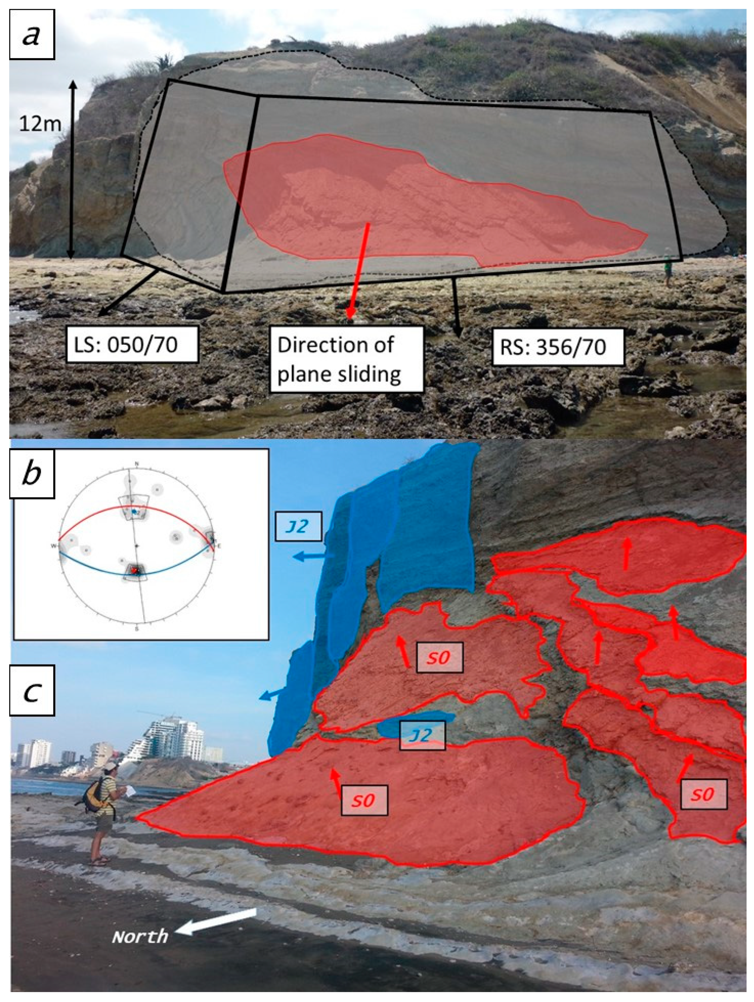
The slope of Figure 4 is the subject of the present study and is a combination of planar sliding and toppling of strata triggered by a set of subvertical discontinuities dipping inland. Barbasquillo Punta (Cape) is a very characteristic planar failure sliding through the stratification. The failure surface does not reach the upper-horizontal part of the cliff because of its low continuity and persistence. It is cut by a vertical fault and some more conjugated joints that delimit a unique block of some cubic meters in volume (Figure 4). This block fell in precedent times and has been completely removed by sea action—erosion and weathering. The peculiarity of this cliff is that it has a dihedral shape similar to a “nose”. This falls under the category of two-faced slopes (see methodology in [1,5]), with the left side of the “nose” watching the cliff from the sea—the left-side slope (LS) has a dip direction of N 050° E and a dip of 70°. The right side (RS) has a dip direction of N 365 E and dips around 70° (Figure 4).
Figure 4a shows Punta Barbasquillo Beach before the cliff failure. Figure 4b is the stereographical representation of the main joints, while Figure 4c is the actual situation indicating the main joint sets determined on the two-faced slope of Barbasquillo. In Figure 4, stratification, or S0, is shown in red, and the joint set named J2, which forms the tension crack and induces the progressive strata toppling, and the third joint set, J1, vertical and minor, are shown in blue.

4.3. Kinematic Assessment

The main join sets are summarized in Table 1, which have been recognized in the geomechanical station (that is, an in situ geomechanical data and parameter observation point) in the back analysis of the failed slope. The field strength of discontinuities (C, φ) was assessed using the Barton–Bandis [13,14] criterion and in situ data (Schmidt hammer, JRC Barton’s comb, etc.). An evaluation of the resistance of the joints has been proposed using parameters that can be obtained in the field without carrying out laboratory tests. For this reason, within the input of the Barton–Bandis criteria, a purely field methodology has been chosen to obtain the joint resistance and roughness.
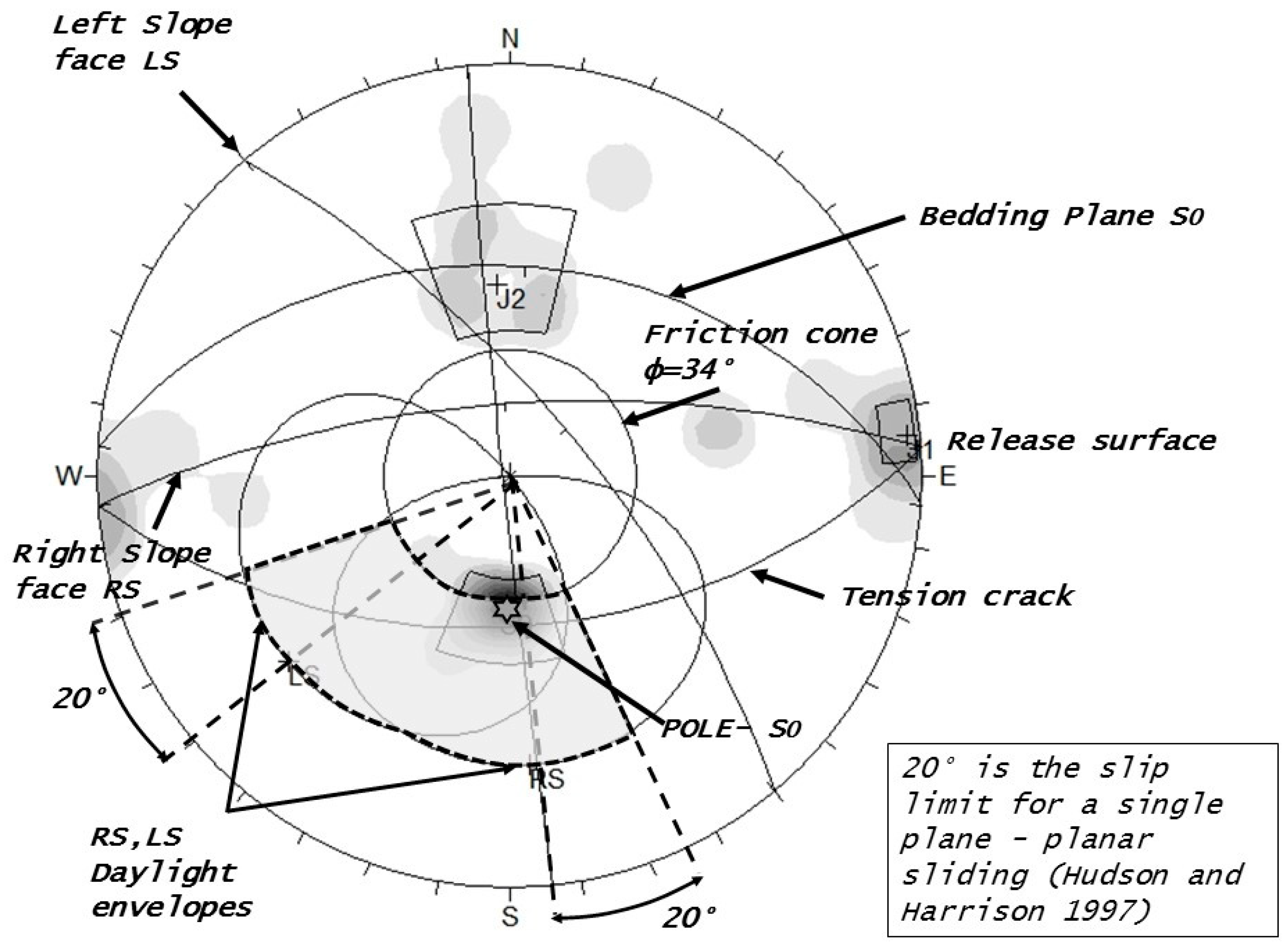
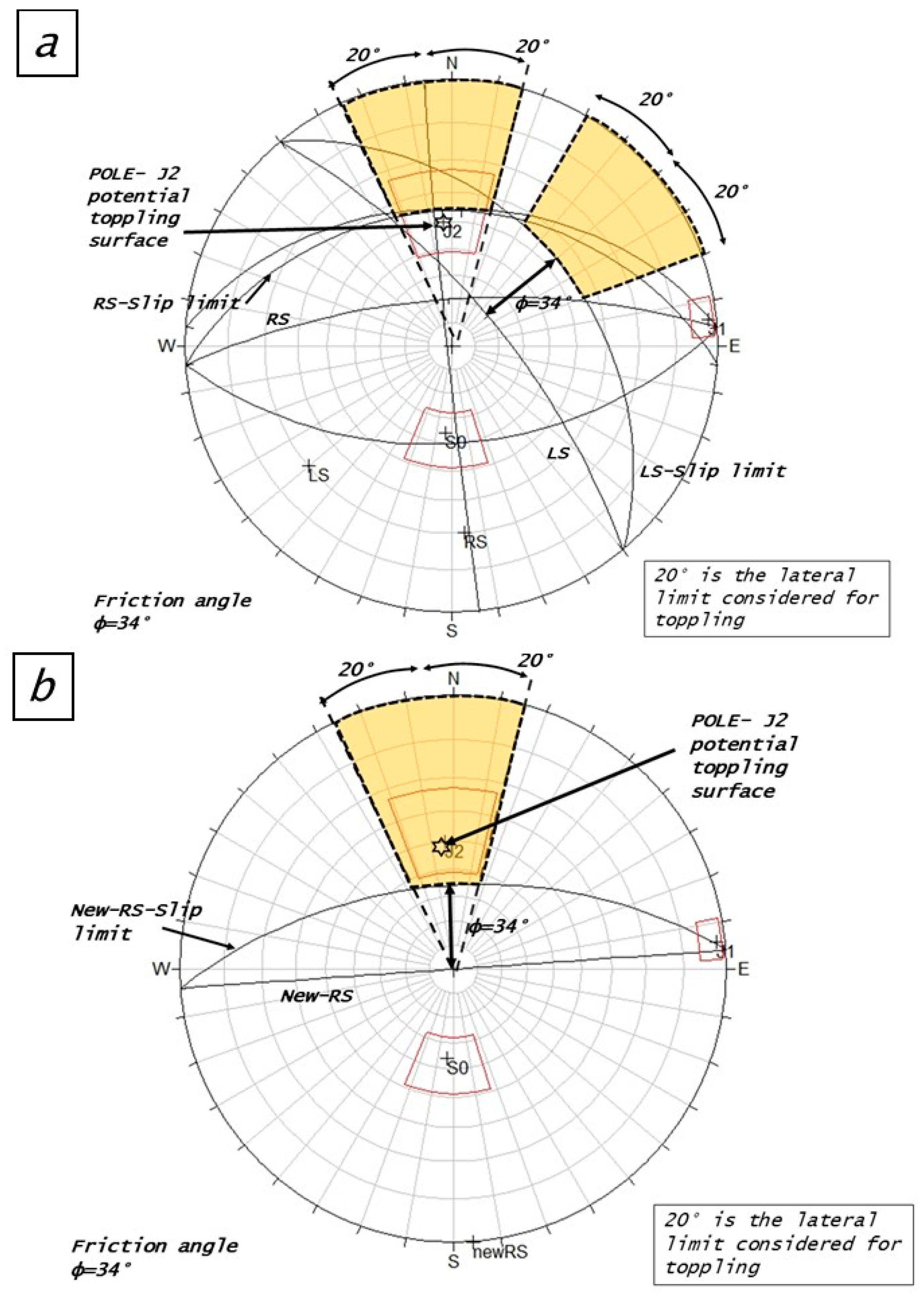
The two front faces of the slope as well as the main joint sets were represented using stereographic projection (Figure 5 and Figure 6). The results of the kinematic assessment indicate that the slope was unstable. The instability can be observed in the joint S0 poles located inside the restricted daylight envelope (Figure 5). The toppling risk that could exist in the cliff before the planar failure was analyzed using projection (see Figure 7). The potential toppling of J2 towards the left (LS) and right (RS) sides of the cliff was also analyzed. The kinematic assessment shows a potential but not important risk: the pole of the joint J2 is not inside the daylight envelope but very close to the limit zone. The J2 should therefore be considered a tension crack. Once planar sliding has occurred, the new slope face overhanging the vertical could trigger both block and flexural toppling (Figure 7b), as can be concluded from the new and wider daylight pole envelope.
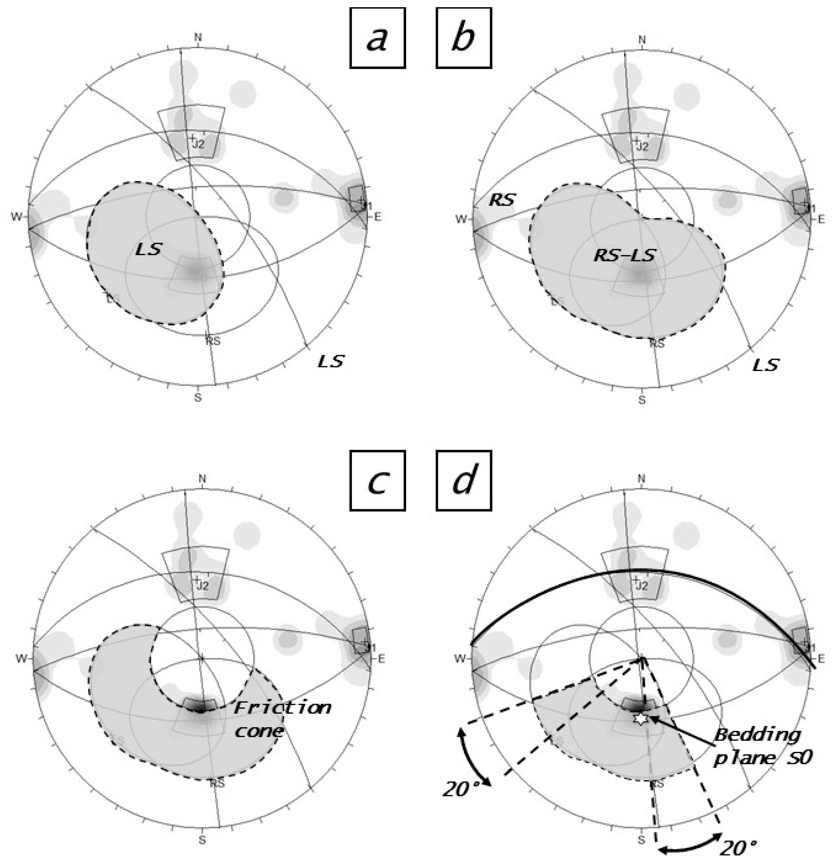
Figure 6a shows the daylight envelope for a single-face LS (Left Side). In Figure 6b, the expanded daylight envelopes for both left and right faces (LS-RS) are shown, while in Figure 6c, it is proposed that the daylight envelope is restricted by the friction cone. The pole of the bedding plane is inside the restricted daylight envelope, so the plane should be considered unstable, as can be deduced by the slope slide failure.
Figure 7a shows the stereoplot assessment of the potential toppling risk in Barbasquillo before the planar sliding. Figure 7b shows the stereoplot assessment of the potential toppling risk in Barbasquillo on the RS slope face in the present situation after planar sliding has occurred.

5. Discussion

We carried out a back analysis of a failed multi-face (MFS) round convex slope. The MFS approach, which combines a multi-face approach and a restricted envelope for poles, can reflect the actual situation and process of the unstable cliff. Often, “real” unstable cliffs show complex geometries such as double-, multi-, or even round-face slopes. These cases can be analyzed by Hemispherical Projection Methods (HPMs) and the kinematic analysis method proposed by Markland [2] and John [3,4]. The analysis of envelopes in the kinematic approach is an efficient and visually very fast way of knowing whether or not a fracture or set can pose a stability problem on a slope in joined rock masses.
In this manuscript, all the slopes are natural cliffs that have suffered collapse, landslides, and progressive toppling controlled by discontinuities. The particularity of the study is the analysis of clearly three-dimensional geometries through stereographic projection. This methodology is clearly applicable to road-cut slopes since it is effective on high mountain routes with many curves.

6. Conclusions

This work is one of the few applications of the multi-faced slope (MFS) kinematic analysis methodology of Yoon et al. [5], together with that of Jordá et al. [1], and the only one to date in South America. It also reinforces the idea of aligning the technique with [12,13]; in these works poles are used instead of planes. [5].
Although it may seem complicated and not very intuitive, representing multi-faced slopes (MFS) in stereography greatly simplifies complex situations. It also allows a quick and effective analysis of an unstable situation. The alternative to this approach is that of models and numerical codes of discontinuities and fractured media, which are not very user friendly and extremely time-consuming. These methods are ineffective for the purpose of this study and for the typology of kinematic breaks clearly identifiable with a stereographic model. In addition, stereographic slope models allow you to easily design a stable slope simply by modifying its slope and seeing the result immediately on the stereogram. The methodology developed and applied here has multiple applications on variable-geometry slopes and curved faces. Among others, we find this type of situation on mountain roads that contour geological structures, and it is also very frequent on coastal cliffs, in river canyons, and in mountain gorges.
The MFS kinematic approximation is sufficiently conservative and yields reliable results, simulating complex realities in a simple and accurate way. Future lines of research may be aimed at other types of slopes in order to expand the method’s database.

Author Contributions

Conceptualization, C.P.B.B. and L.J.B.; methodology, L.J; validation, L.J.B. and C.P.B.B.; formal analysis, L.J.B.; investigation, C.P.B.B. and L.J.B.; writing—original draft preparation, C.P.B.B. and L.J.B.; writing—review and editing, C.P.B.B. and L.J.B.; visualization, L.J.B.; supervision, L.J.B. All authors have read and agreed to the published version of the manuscript.

Funding

This research received no external funding.

Institutional Review Board Statement

Not applicable.

Informed Consent Statement

Not applicable.

Data Availability Statement

The data presented in this study are available on request from the corresponding author.

Conflicts of Interest

The authors declare no conflict of interest.

References

  1. Jordá-Bordehore, L.; Jordá-Bordehore, R.; Romero-Crespo, P.L. Kinematic assessment of multi-face round slopes using hemispherical projection methods (HPM). Soils Rocks 2016, 39, 167–176. Available online: https://www.scopus.com/inward/record.uri?eid=2-s2.0-85021016216&partnerID=40&md5=28a6c438faa7b680ecced3520cf1509c (accessed on 7 July 2023). [CrossRef]
  2. Markland, J.T. A useful technique for estimating the stability of rock slopes when the rigid wedge sliding type of failure is expected. Imp. Coll. Rock Mech. 1972, 10, 10. [Google Scholar]
  3. John, K.W. Graphical stability analysis of slopes in jointed rock. J. Soil Mech. Found. Div. 1968, 94, 497–526. [Google Scholar] [CrossRef]
  4. John, K.W. Graphical Methods for Slope Stability Analysis. In Rock Mechanics. International Centre for Mechanical Sciences; Springer: Vienna, Austria, 1972; pp. 221–239. [Google Scholar]
  5. Yoon, W.S.; Jeong, U.J.; Kim, J.H. Kinematic analysis for sliding failure of multi-faced rock slopes. Eng. Geol. 2002, 67, 51–61. [Google Scholar] [CrossRef]
  6. Hudson, J.; Harrison, J. Engineering Rock Mechanics—An Introduction to the Principles; Pergamon, E., Ed.; Imperial College: London, England, 1997. [Google Scholar]
  7. Wyllie, D.C.; Mah, C.W. Rock Slope Engineering. Civil and Mining; CRC Press: New York, NY, USA, 2004. [Google Scholar]
  8. Lisle, R.J. Calculation of the daylight envelope for plane failure of rock slopes. Geotechnique 2004, 54, 279–280. [Google Scholar] [CrossRef]
  9. Lisle, R.J.; Leyshon, P.R. Stereographic Projection Techniques for Geologists and Civil Engineers; Cambridge University Press: Cambridge, UK, 2004; ISBN 0521535824. [Google Scholar]
  10. Delgado-Reivan, X.; Paredes-Miranda, C.; Loaiza, S.; Echeverria, M.D.P.V.; Mulas, M.; Jordá-Bordehore, L. Stability Analysis of Rocky Slopes on the Cuenca–Girón–Pasaje Road, Combining Limit Equilibrium Methods, Kinematics, Empirical Methods, and Photogrammetry. Remote Sens. 2023, 15, 862. [Google Scholar] [CrossRef]
  11. Villalta Echeverria, M.D.P.; Viña Ortega, A.G.; Larreta, E.; Romero Crespo, P.; Mulas, M. Lineament Extraction from Digital Terrain Derivate Model: A Case Study in the Girón–Santa Isabel Basin, South Ecuador. Remote Sens. 2022, 14, 5400. [Google Scholar] [CrossRef]
  12. Flor-Jiménez, M.; Avilés-Moran, H.; Villalta-Echeverría, M.; Murillo-Lozano, I.; Escobar-Segovia, K.; Mulas, M. Geotechnical and structural characterization of the Ignimbritas of the Saraguro group in the sector of Santa Isabel-Pucará, Ecuador [Caracterización geotécnica y estructural de las Ignimbritas del grupo Saraguro en el sector de Santa Isabel-Pucará, Ecuado]. In Proceedings of the LACCEI international Multi-conference for Engineering, Education and Technology, Montego Bay, Jamaica, 24–26 July 2019. [Google Scholar]
  13. Barton, N.; Bandis, S. Review of predictive capabilities of JRC-JCS model in engineering practice. In Proceedings of the Rock joints: Proceedings of the International Symposium on Rock Joints, Loen, Norway, 4–6 June 1990; pp. 603–610. [Google Scholar]
  14. Barton, N.; Bandis, S. Effects of Block Size on The Shear Behavior of Jointed Rock. In Proceedings of the Proceedings—Symposium on Rock Mechanics, Berkeley, CA, USA, 25–27 August 1982; pp. 739–760. Available online: https://www.scopus.com/inward/record.uri?eid=2-s2.0-0020287706&partnerID=40&md5=5d336118bb29748ae5eee8962f78b3ca (accessed on 7 July 2023).
  15. Bordehore, L.J.; Riquelme, A.; Cano, M.; Tomás, R. Comparing manual and remote sensing field discontinuity collection used in kinematic stability assessment of failed rock slopes. Int. J. Rock Mech. Min. Sci. 2017, 97, 24–32. [Google Scholar] [CrossRef] [Green Version]
  16. Dips Version 5.0 Graphical and Statistical Analysis of Orientation Data; Rocscience Inc.: Toronto, ON, Canada, 2001; Available online: https://www.rocscience.com (accessed on 7 July 2023).
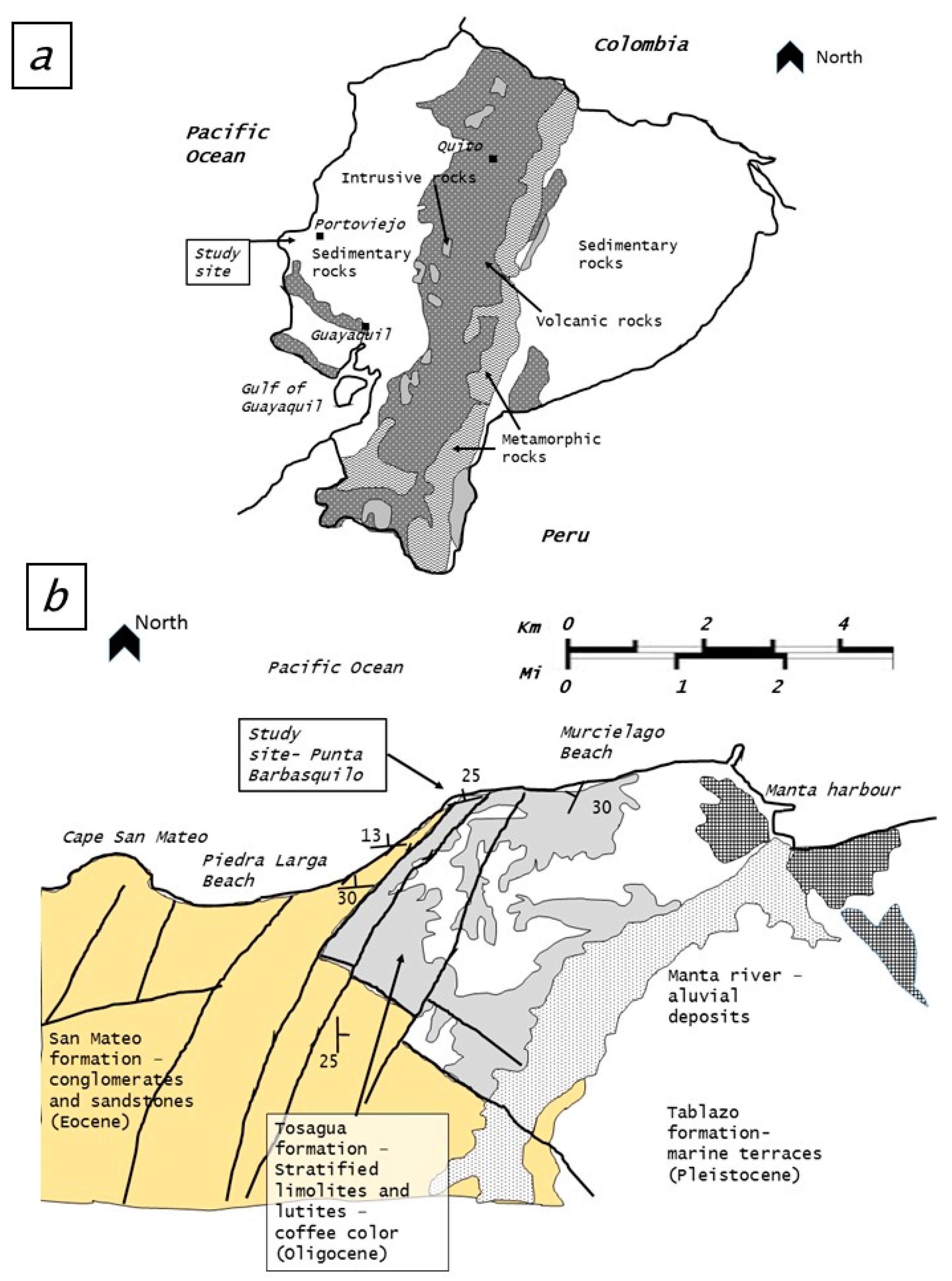
Figure 1. Lithologies of Ecuador (a) and geological context of the Manabi–Manta coast (b).
Applsci 13 08245 g001
Figure 2. Panoramic view of Manta’s coastline and its main types of rock cliffs: Images (a,b) hotels and buildings on top of the coast cliff, (c,d) show the basal strata, (e) shows relevant joints and (f) is the Punta Barbasquillo.
Applsci 13 08245 g002
Figure 3. Scheme showing typical failure modes on Piedra Larga Beach (a) and Barbasquillo (b).
Applsci 13 08245 g003
Figure 4. Scheme of Punta Barbasquilo before (a) and after the slope failure (c). Image (b) shows the stereogram of the slope and main joint set.
Applsci 13 08245 g004
Figure 5. Stereographic representation of the joints and planes existing in the Barbasquillo slope using DIPS software [16].
Applsci 13 08245 g005
Figure 6. Process to design the restricted daylight envelope for a double-face slope Right and Left (RS-LS) following the Jorda et al. [1] methodology. Images (a,b) show the daylight envelope construction; image (c) is the intersection with the friction cone and (d) is the “restricted daylight envelope” with the lateral limits for planar failure.
Applsci 13 08245 g006
Figure 7. Stability assessment stereoplot before and after the Barbasquillo cliff’s progressive failure. Image (a) shows the actual potential toppling failure for the right and left sides of the cliff: the slope dip angle is 70 degrees. Image (b) shows an unstable J2 joint because the pole falls into the yellow envelope: that was the initial situation when the cliff was vertical (90 degrees dip).
Applsci 13 08245 g007
Table 1. Joint sets in the slope analyzed in Punta Barbasquillo.
Join SetKind of JointDip Dir (Degrees)Dip (Degrees)K Fisher Statistical DistributionJoint Cohesion and Friction
S0Stratification-sliding surface004°36°106C = 0
φ =34°
J1Joint264°88°2816
J2Joint—tensión crack176°50°38
Disclaimer/Publisher’s Note: The statements, opinions and data contained in all publications are solely those of the individual author(s) and contributor(s) and not of MDPI and/or the editor(s). MDPI and/or the editor(s) disclaim responsibility for any injury to people or property resulting from any ideas, methods, instructions or products referred to in the content.