Article

A Numerical Study of the Behavior of Micropile Foundations under Cyclic Thermal Loading

by
Arianna Lupattelli
1,
Peter J. Bourne-Webb
2,
Teresa M. Bodas Freitas
2 and
Diana Salciarini
1,*
1
Department of Civil and Environmental Engineering, University of Perugia, Via G. Duranti, 93, 06125 Perugia, Italy
2
Civil Engineering Research and Innovation for Sustainability (CERIS), Instituto Superior Técnico, ULisboa, Avenida Rovisco Pais, 1, 1049-003 Lisbon, Portugal
*
Author to whom correspondence should be addressed.
Appl. Sci. 2023, 13(17), 9791; https://doi.org/10.3390/app13179791
Submission received: 29 July 2023 / Revised: 18 August 2023 / Accepted: 23 August 2023 / Published: 30 August 2023
(This article belongs to the Special Issue Advanced Numerical Simulations in Geotechnical Engineering II)

Abstract

:
Micropiles are small-diameter foundation elements that are widely used in building refurbishment to reinforce existing foundations or provide new foundations where access for construction is difficult. Thermally-activated (TA) micropiles could be useful as an efficient means of providing cost-effective ground-coupling when shallow geothermal energy systems are considered in building rehabilitation. It is well-established that thermal activation of pile foundations results in thermo-mechanical interactions between the pile and the surrounding soil. These thermally-induced effects need to be examined to ensure that they do not adversely impact the load transfer function of the micropile. Numerical analysis is able to produce reliable predictions of thermo-mechanical behavior of TA piles, and this study applied this technique to examine the cyclic thermal behavior of micropiles, isolated and in groups. For the situations considered in this study, it is shown that during cyclic thermal activation, irrecoverable movements are unlikely to be significant in design terms, if the initial mobilization of the shaft resistance is low. Though stable, cyclic thermal movement amplitudes are large enough that they should be considered in design. The study highlights that large changes in thermal stress can develop and be locked-in to the response of long flexible piles, and that these should be verified in design. Further, as pile spacing reduces, thermal interference results in a loss of heat exchange capacity per pile, which has to be considered in the design of large groups of TA micropiles. Therefore, TA micropiles can offer an efficient and secure means of providing ground coupling in shallow geothermal energy systems.

1. Introduction

Thermally-activated (TA) piles are the most frequently employed energy geo-structure and work both as load-bearing elements and ground heat exchangers within a shallow geothermal energy (SGE) system [1]. TA piles provide clear advantages over conventional borehole and trench based SGE systems, primarily through the elimination of these costly groundworks. TA piles were first used in Austria in the 1980s [2] but their use has accelerated in the last two decades [3]. To date, the main use of TA piles has been in new build construction.
The integration of SGE into building rehabilitation is a major challenge, not least in terms of how to obtain efficient and cost-effective ground-coupling [4]. For projects that require foundation strengthening, that are also considering the installation of SGE, thermal activation of micropile foundations presents an opportunity to provide the ground-coupling efficiently, and more economically than using separate borehole heat exchangers. Illustrating the feasibility of TA micropiles, [2,5,6] described examples of bored reinforced concrete, driven steel tube and drilled TA micropile systems, respectively, and [7] evaluated various construction details for underpinning projects incorporating TA micropiles.
Micropiles are defined as bored (replacement) piles with diameters less than 300 mm and driven (displacement) piles with diameters less than 150 mm [8]. Four basic types of bored micropile are used: Type A, where the grout filling the pile bore is placed under gravity alone; Type B, low-pressure grouted piles; Type C, high-pressure grouted piles; and Type D, high pressure repeatedly and selectively grouted piles [9]. In this study (and others discussed below), only micropile Types A and B have been considered. The construction of Type C and D micropiles involves high-pressure grouting which may preclude the possibility of thermally activating these pile types. Additionally, the expanded grout bodies and/or irregular grout permeation associated with high pressure grouting complicates the analysis of Type C and D bored micropiles. Due to the small dimensions of the equipment used in their construction, micropiles are particularly well suited for situations where access is difficult, e.g., when the foundations of an existing building require strengthening during rehabilitation. Although it is possible to install them to greater lengths, micropiles typically have lengths in the range of 15 to 30 m [9,10].
Although considerable research has been undertaken to develop a better understanding of the mechanisms of behavior of TA piles to provide assurance regarding the efficacy and safety of the application in SGE systems [11,12,13,14], only a few studies refer specifically to micropiles [15,16]. Indeed, of 26 field tests reviewed, just 9 involved TA micropiles [17,18,19,20,21,22,23,24,25]. Of these studies, the thermo-mechanical response of TA micropiles was only reported by [17] (bored), and [24,25] (driven), and in all three cases, the piles were installed in fine-grained soils. Furthermore, numerical analysis of TA micropiles has been reported by [25,26,27,28] where driven micropiles in fine-grained soils were modeled, and [29] who modeled a bored (wished-in-place) micropile in frictional media.
The thermal response of TA piles of all types was reviewed by [30], and more recently by [31]. For micropiles, including those referred to above, thermal tests have yielded heat transfer rates in the range of 15 to 70 W/m. This is a rather wide range which is probably due to a multitude of factors such as ground and groundwater conditions, pile construction method and materials, the configuration of heat exchange pipes in the piles and the thermal load parameters (inlet temperatures, flow rates and duration). Heat transfer rates from intermittent tests, where the thermal loads are applied for only a few hours, lie at the upper end of the above range and those rates from long-term tests that approach steady state tend towards the lower end.
Building upon this, a comprehensive understanding of heat transfer in micropiles was further developed by [32] who employed Taguchi statistical experimental design techniques to methodically establish and conduct analyses that were instrumental in identifying the pivotal factors that influence heat transfer within micropiles. The results showed that different design criteria to those for large diameter TA piles should be used for TA micropiles. In addition to pile length and thermal conductivity, the diameter of the heat exchanger pipes emerged as one of the key parameters for optimizing heat exchange efficiency in micropiles, while being the easiest parameter to engineer. On the other hand, while maximizing the number of U-pipes and pile diameter was crucial for large diameter TA piles, it did not impact the energy performance of TA micropiles, due to geometry constraints and the expected occurrence of thermal interference.
Some field investigations on the thermal behavior of TA micropiles were carried out by [23] who performed thermal testing on a 180 mm diameter, 12 m long micropile installed into layered clayey and sandy silt, and reported heat transfer of 30 to 40 W/m with an inlet temperature, Tin, of about 34 °C and a fluid flow rate of 0.82 m/s (0.1 kg/s). Ren et al. (2020) [24] and Kong et al. (2021) [25] undertook heating and cooling tests on a group of eight 160 mm diameter, 13 m long micropiles in clayey soil underpinning an existing foundation, and reported heat transfer increasing from 20 to 70 W/m, as the inlet temperature was increased from 30 °C to 50 °C, at a flow rate of 0.51 m/s (0.113 kg/s). Modeling balanced seasonal heat exchange through an isolated 150 mm diameter, 15 m long micropile using the finite element method, [29] obtained peak heat exchange values of about 45 W/m for both heating (Tin = 0 °C) and cooling (Tin = 30 °C) modes with flow rates between 0.5 and 1.5 m/s (0.09–0.27 kg/s), during the first annual cycle of thermal loading. The authors are not aware of any long-term performance data from micropile-based TA pile foundation systems.
Akrouch et al. (2014) [17] tested two 180 mm diameter, 5.5 m long Type A micropiles constructed in a very stiff, high plasticity clay, and reinforced with a single 25 mm diameter steel reinforcement bar. Non-TA piles of the same dimensions were also tested, to provide a measure of pile creep and capacity under tensile mechanical load. A number of thermal tests were carried out under tensile mechanical loads that increased progressively from 40 kN up to 256 kN, about 9% to 56% of the ultimate tensile resistance. The results suggested that the thermal axial load generated during heating was very small (around 20 kN) which implied little shaft restraint was mobilized. Drawing upon the insights garnered from previous studies, particularly the examination of TA micropiles by [17], it becomes evident that the influence of mechanical load on thermal behavior is a crucial factor. The observations undertaken by [17] regarding tension cracks forming in the grout body due to mechanical load-induced strain shed light on the significance of tension cracking. This concept was further reinforced by the work of [33], who demonstrated that tension cracks in the pile grout body can substantially mitigate the thermal axial load when subjected to tensile loading, resulting in minimal shaft restraint and limited impact on the pile–soil interface.
In a different vein, the field tests conducted by [24] and [25] delved into the thermo-mechanical behavior of a group of steel-pipe micropiles, offering a distinct perspective on heat exchange efficiency. The field tests described by [24] and [25] monitored the thermo-mechanical response of a group of eight steel-pipe micropiles which were used to underpin an existing 600 mm diameter, 8 m long pile. Within the micropile group, two of the eight piles were instrumented and thermally activated. Ren et al. (2020) [24] reported that the heat exchange efficiency of the steel-pipe TA micropiles used in the tests decreased as the number of thermal cycles increased. They also showed that the heat exchange efficiency under summer conditions was higher than in winter conditions, and confirmed that an intermittent mode of operation delivered better heat exchange efficiency than the continuous mode. Heat exchange per unit length was comparable to the values quoted earlier. The maximum axial thermal stress in the micropiles slightly increased with the number of cycles under the intermittent operation mode and a residual thermal stress was recorded when the temperature returned to its initial value. Both the reduction in heat exchange efficiency and the residual stress generation could perhaps be attributed to an accumulation of heating or cooling with time, i.e., the pile and soil were not returning to ambient conditions during the recovery periods. Building upon these findings, [25] validated a finite element model against experimental outcomes, shedding light on the intricate interplay between heat exchange potential and the configuration of thermally-activated micropile groups. As more piles within the group were thermally activated, the total heat exchange power increased, although the average heat exchange power per pile diminished due to thermal interference among adjacent piles.
The specific problems addressed by this study pertain to the limited understanding surrounding the thermal and thermo-mechanical performance of micro-piles, thereby imposing potential constraints on their applicability in building developments, including refurbishments. This research aims to investigate these issues comprehensively through numerical analysis. The primary focus lies in scrutinizing the thermo-mechanical response of micropiles, both as single (isolated) installations and in group configurations, under compressive loading conditions. By undertaking this examination, the study seeks to illuminate any disparities in thermo-mechanical behavior compared with their larger-diameter counterparts, which were investigated in a parallel study [34].

2. Basis for Numerical Analyses

2.1. Geometry

The numerical analyses presented here were undertaken using the finite-element program ABAQUS 2016 [35]. A two-dimensional (2D) axisymmetric pile geometry was considered, which comprised a 200 mm diameter micropile with a TA length of either 30 m (designated MP-30) or 15 m (MP-15), embedded in a domain that was either 91 m or 45.5 m deep, Figure 1b,c). Utilizing a 2D axisymmetric modeling approach provides notable advantages in computational efficiency, precision, and simplified configuration for geotechnical challenges exhibiting rotational symmetry, as exemplified by the case of piles and the soil domain. The thermally-activated part of the pile started 1.0 and 0.5 m below ground level for MP-30 and MP-15 respectively, to provide a buffer between the thermal boundary conditions applied in the pile and along the ground surface; this had only a minor effect on the reported pile behavior. This is a generic study, however, the pile lengths modeled are representative of typical micropile installations and also allowed the influence of the effect of the changes in geometry between the large diameter (LD) piles considered previously [34] and the micropiles considered herein.
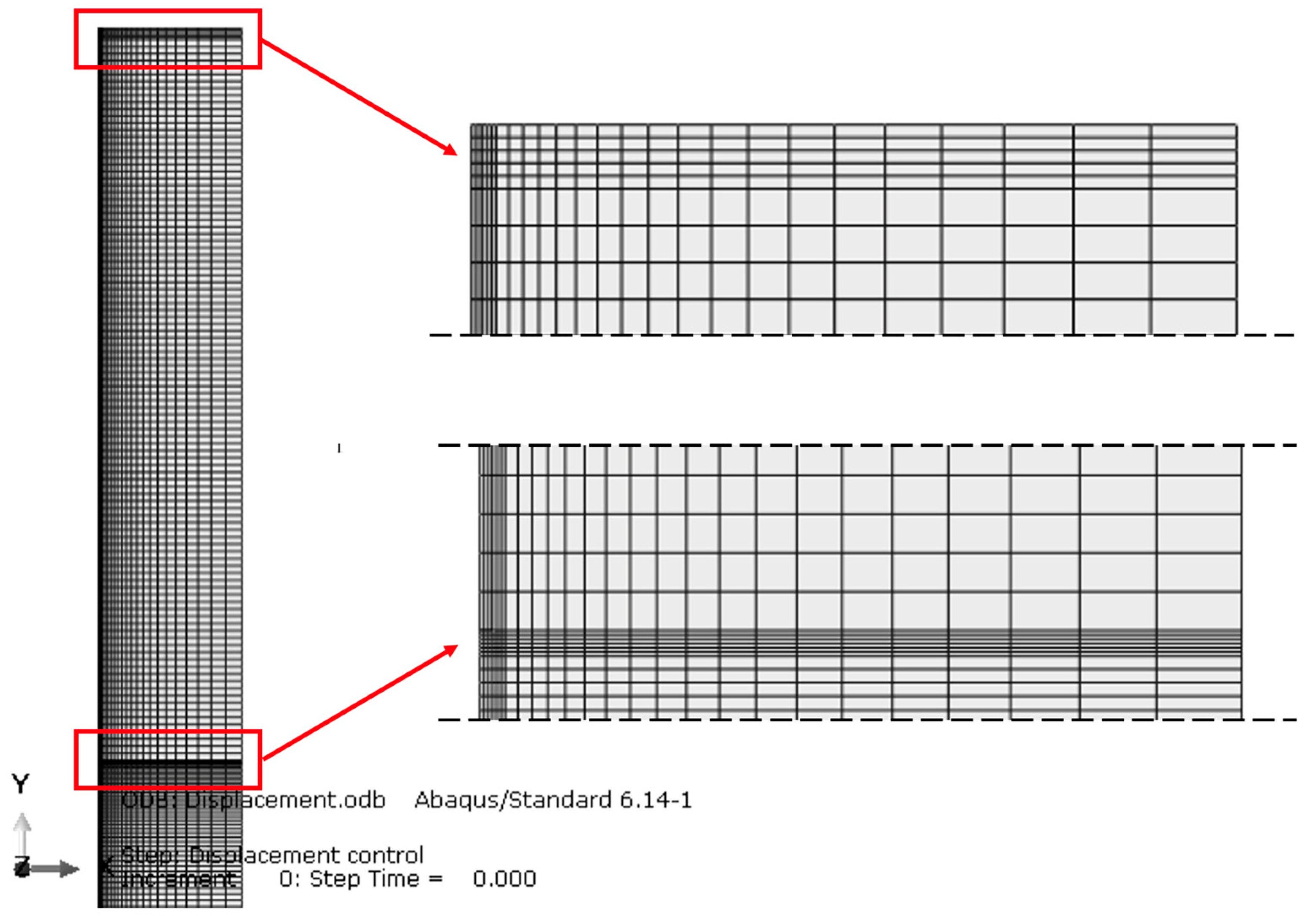
The model was discretized, as shown in Figure 2, by means of a mesh defined by 5421 quadrilateral elements of type CA4XT [35], i.e., coupled temperature-displacement elements for which the stress analysis depends on the temperature solution and the thermal analysis depends on the displacement solution.
The lateral dimension of the finite element mesh was set to provide mesh radius to pile diameter ratios, R/D of 30, 8 and 4 (R = 6, 1.6 and 0.8 m). Initial analyses (not presented, and see, e.g., [34]) showed that when R/D = 30, the pile could be considered to be isolated and not influenced by mechanical and thermal boundary conditions on the side boundary. With smaller values of R/D, the problem could be considered as a “unit cell” that represents an idealized pile group that extends to infinity. Zito (2019) [36] undertook a full three-dimensional analysis of the same problem and demonstrated that the unit cell approach approximated this reasonably closely, with the benefit of a much-reduced computational effort, confirming the results of previous studies including [37,38,39], among others.
The bottom boundary was fixed in the vertical and horizontal directions while the side boundary was only fixed in the horizontal direction, Figure 1b,c. Thermal boundary conditions are outlined in Section 2.3, with climatic boundary conditions based on those for a humid subtropical climate such as Milan, Italy (https://www.timeanddate.com/weather/italy/milan/climate (accessed on 20 May 2022).

2.2. Material Thermal and Mechanical Properties

The medium supporting the pile was assumed to be frictional and was assigned parameters typical for a dense sand, as per [40]. It was modeled as linear elastic-perfectly plastic, with a Mohr–Coulomb failure criteria and assuming a non-associated flow rule, with the properties outlined in Table 1. In using this soil model, it was recognized that it did not reproduce a number of the known aspects of granular soil behavior including stress path dependency, and stress and strain dependency of the soil stiffness [41]. It can, however, provide reasonable estimates of failure for boundary value problems involving granular soils and interfaces, capturing the basic idea of shear strength increasing with effective stress. While more complex models for granular soil behavior are available [42], the model has been successfully employed in the back-analysis of TA pile tests [43,44,45], and it is considered that the model is, therefore, sufficient, and its simplicity allows the focus of this work to be maintained. The Young’s modulus for the soil approximates Equation (1), with a stepwise variation that increases with depth. As seen in Figure 1a, Equation (1) captures the stress dependency of soil stiffness which allows the increase in stiffness with depth to be approximated. This yields an average soil Young’s modulus over a depth equal to the length, L, of the piles, of 129 and 91.3 MPa for MP-30 and MP-15, respectively.
E = 1.2 p a   σ h p a 0.5
where pa = atmospheric pressure = 101.3 kPa, and σ’h = horizontal effective stress.
The micropile was modeled as a linear elastic material (Han et al., 2023) [46], with the properties detailed in Table 1. The effective stiffness of the micropile was determined based on a composite section in which it was assumed that a 140 mm diameter steel tube with a wall thickness of 10 mm extended the full length of the micropile, and the grout comprising the rest of the pile body had a stiffness of 12 GPa [47,48]. Concerning the tangential behavior, the pile–soil interface was modeled by attributing a “penalty” friction formulation, where the contact between the two materials is imposed by means of a shearing resistance that is proportional to the normal stress, i.e., τ = σn.μ, where μ is a friction coefficient (Table 1) [49,50]. The friction coefficient μ = tanφcs’ assumes that a critical state angle of shearing resistance, φcs’ = 32°, is applicable on the contact with a value of 0.624 (Fleming et al., 2009) [51]. Initial analyses of the piles under axial mechanical load were run in order to define the parameter representing the relative displacement at which the contact shearing resistance was fully mobilized, and a value of 0.002 m was chosen. Regarding the normal behavior at the interface, a pressure-overclosure of “hard contact type” was selected.
In granular media, the permeability tends to be sufficiently large that load and thermally induced excess pore water pressures are not likely to be significant [52,53]. The analyses undertaken assumed the soil was dry, which would alter (increase) the absolute ultimate pile resistance values relative to, e.g., saturated conditions, but it was expected that the relative effects and the conclusions reported in this study will be similar.
The thermal properties for the micropile and soil are largely generic, however, they were selected as being representative of concrete [54] and soil [55].

2.3. Initial and Boundary Conditions and Modeling Sequence

The analyses presented follow a four-stage sequence as described below:
  • The problem domain was initialized with an initial stress phase, based on a value of the at-rest earth pressure coefficient, K0 of 0.429, and an initial temperature, T0 of 14 °C;
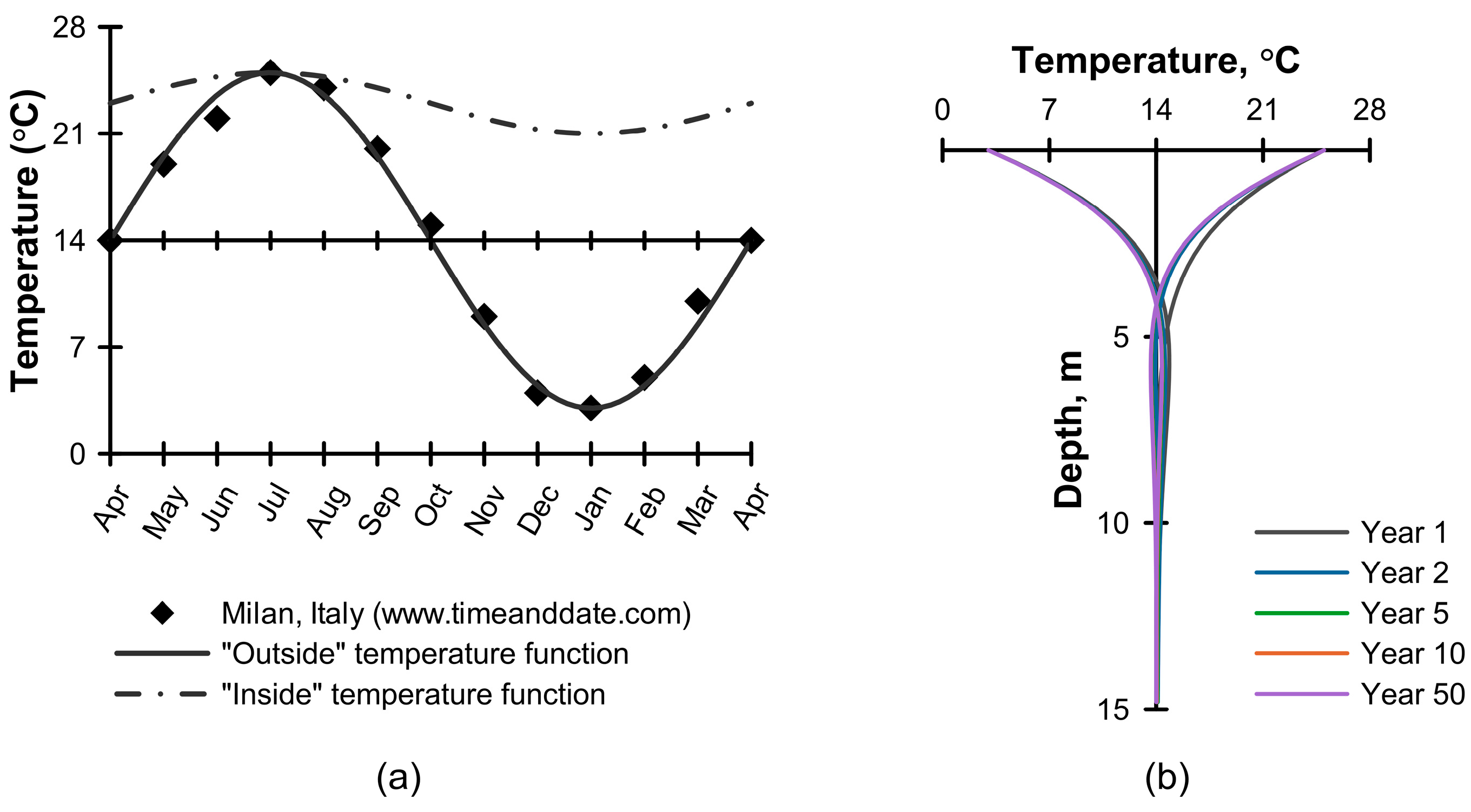
  • Recognizing that the near-surface region of the ground is influenced by seasonal climate variations, in this stage, a transient thermal analysis was undertaken in order to establish the extent of this region. To achieve this, a periodic temperature function, Equation (2) and Figure 3a, was applied at the ground surface over a period of 10 years, which was found to be sufficient to establish a dynamic thermal equilibrium with the imposed boundary condition, Figure 3b.
T = Tavg + ΔT sin [2πt/P]
where Tavg = T0 = 14 °C is the average annual air temperature; ΔT = 11 °C is the temperature amplitude; P = 1 year is the period of the function, and t (years) is the time since the start of the calculation stage. In this phase of the calculation, adiabatic conditions were assumed along the side boundaries and a constant temperature (T0 = 14 °C) was specified on the bottom boundary.
  • The pile was wished-in-place and then the allowable service load, Fa (see Section 3.1.1) was applied;
  • Operational thermal activation of the pile was then modeled for a duration of 10 years, through a “coupled temperature-displacement (transient)” procedure. This was achieved by applying a periodic temperature change over the length of the pile, on the centerline of the micropile. This approach was considered reasonable following the work of [29] which found that thermal load applied as a temperature at the pipe position in a micropile gave similar responses to that obtained by modeling the pipe flow using one-dimensional, forced-convection elements.
The imposed temperature followed Equation (2) with Tavg = 14 °C; ΔT = 12 °C. Each simulation started from T = Tavg and with a season for which there was a need for cooling (and, therefore, pile heating, for heat injection into the ground). It can be noted that analyses starting with a heating season (pile cooling) showed some small differences in the first few thermal cycles but converged to the same response as reported herein and thus, are not shown. This fourth stage was run with one of two surface temperature boundary conditions:
  • An “outside” condition, as described above was maintained to represent an outdoor environmental condition which would be consistent with, e.g., the running of a pile load test;
  • An “inside” condition was modeled, again using Equation (2) but with Tavg = 23 °C, ΔT = 2 °C and P = 1, Figure 3a, which represents the indoor thermal comfort condition for a structure supported on the pile foundation.
The following sign convention is used herein: tension, upwards displacement, and interface shear stress due to pile upwards displacement relative to the soil, are positive.

3. Results and Discussion

3.1. Mechanical Behavior

3.1.1. Load-Displacement Response of an Isolated Pile

The design of axially loaded micropiles broadly follows the same procedures as those for large diameter piles, see, e.g., [56] where the desired outcome is for a pile that operates safely and within acceptable movement limits. In this case, floating bored (Type A and B) micropiles are considered and only the resistance on the pile shaft is used to meet the geotechnical design requirements. The base resistance is ignored because often it is a small component of the total resistance and there is always some uncertainty as to its reliability, due to the possibility of either soil disturbance or drilling debris remaining in the bottom of the pile bore.
When used as a conventional load bearing element, allowable compression and tension loads, Fa, applied to a micropile in service will be derived from the ultimate shaft load resistance, Rs,u, divided by a suitable factor of safety on shaft resistance FS-shaft. For micropiles, the value for FS-shaft used in practice varies between 2.0 and 2.5, depending on the level of field testing to be undertaken to prove the resistance values [57]. A similar range of global factor of safety is arrived at depending on the proportion of variable loading when applying [58]. The micropile analyses undertaken in this study were, therefore, based on FS-shaft = 2, i.e.,
F a , M P = R s , u 2.0
where the ultimate shaft resistance, Rs,u was defined as the value of the shaft resistance mobilized at a settlement equal to 25% of the pile diameter (D), during an analysis of the pile under mechanical compression load and using the largest domain radius (R/D = 30), which allows the pile to be considered as isolated, Figure 1. When used for settlement control, as envisaged by the original pali radici method [10], the design factor of safety may be lower than two, but this has not been considered here, as the design of pali radici depends on an analysis of strain compatibility between the existing foundation and the micropiles.
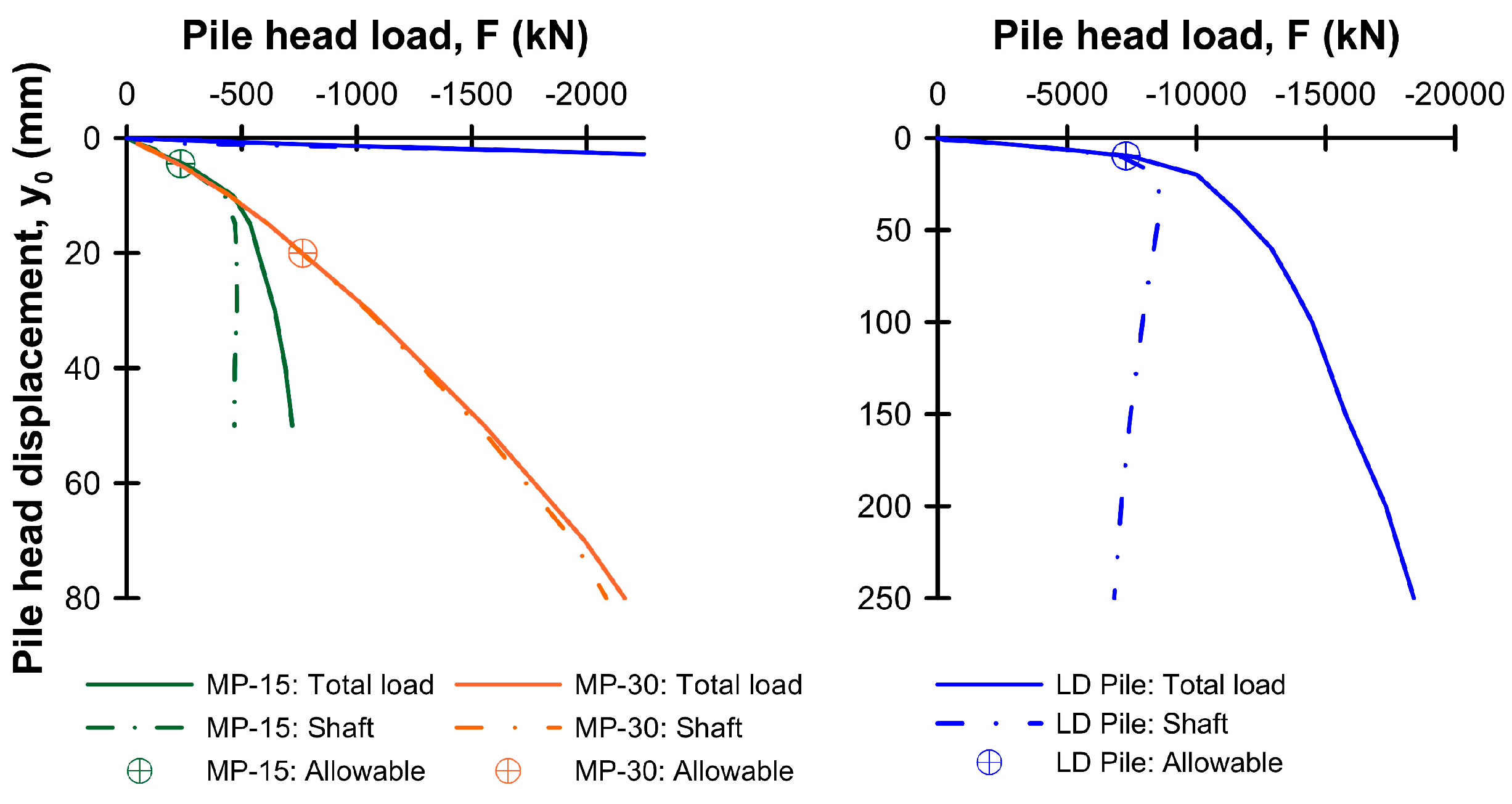
Figure 4 illustrates the predicted load-displacement response of the micropiles, along with the results for a large diameter (LD) pile, as reported in [34]. Based on these analyses and with the value for Rs,u taken at a pile settlement ratio, y/D = 25%, Equation (3) was used to define the allowable service load, Fa (Table 2), used in the thermo-mechanical analyses that follow, for the micropile cases. Additionally indicated are the assessed ultimate resistance and the global factor of safety (FS-global = Rc,u/Fa) which includes the contribution from the base resistance. The values associated with the LD pile given in the table were defined in [34].
Although the total resistance available was markedly different, the form of the load-displacement response of MP-15 and LD pile was similar, with the shaft resistance providing about 60% and 40% of the ultimate resistance (Rc,u) quoted in Table 2, respectively. The load displacement response of MP-30 was quite different, however, and could be explained by the influence of elastic-shortening of the pile itself. Based on an assumption of linear load transfer with depth, elastic-shortening of 9, 40 and 3 mm were predicted for MP-15, MP-30 and the LD pile at their respective ultimate loads. Clearly, for MP-15 and the LD pile, there was significant additional settlement mobilized by the loading, beyond that of elastic-shortening that was associated with load transfer to the ground on the pile-shaft interface and base, of which the former was clearly fully mobilized. However, the elastic shortening on the MP-30 pile was so significant that even after extending the analysis to a displacement of 75 mm, the mobilized base reaction was still very small, Figure 4.
Figure 5 compares the shear stress mobilized on the pile–soil interface of the piles at the allowable and ultimate loads (y0/D = 25%). To allow ready comparison, the theoretical ultimate shear stress based on Equation (4) is also shown (dashed grey line):
qs,u = K0 σ’vμ
where K0 and μ were defined in Section 2 and Table 1, and the vertical effective stress along the pile, σ’v = ρgz/103 (kPa) where z is the depth, g is gravitational acceleration (9.81 m/s2), and the density ρ is defined in Table 1. It was apparent that the shear stress values mobilized were somewhat higher than those suggested by Equation (4). These were examined further, and the discrepancy was found to be due to small changes in the horizontal stresses acting on the pile, due to radial expansion (Poisson’s ratio effect) that developed during mechanical loading, with the effect on the micropiles being somewhat larger due to their lower stiffness.
At failure (y0/D = 25%), the shear stress was close to fully mobilized over most of the pile length, except close to the pile base where the shear stress dropped below the theoretical ultimate values, Figure 4. For MP-30, this was due to the incomplete mobilization of the shaft, as confirmed by the mobilized shear stress profile at a pile settlement ratio, for y0/D = 40%, where the shaft resistance was close to fully mobilized. In MP-15 and the LD pile case, however, the shaft was fully mobilized, and the effects seen close to the pile base were in part due to the base loading mechanism which caused the vertical stress, and hence, the available shear stress, to reduce locally.
Bourne-Webb et al. (2022a) [34] introduced the initial shaft resistance mobilization ratio, M, which was defined as the ratio between the total shaft resistance mobilized under the allowable service load to the maximum available shaft resistance, and was proposed as an indicator for assessing the likely response of piles under cyclic thermal loading. For the micropiles considered herein, the ratio M was 54% and 50% for MP-15 and MP-30, compared with 80% for the LD pile, despite the allowable load being defined based on a FS-shaft = 2 in all cases. This difference was largely due to the relatively small contribution of the pile base resistance to the total compression resistance of the micropiles, compared with the LD pile.
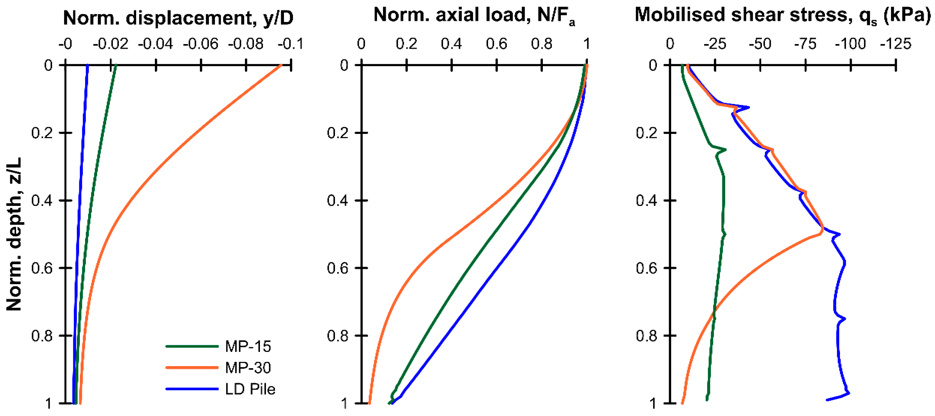
Figure 6 presents a comparison of the normalized response of the three pile cases, with the pile depth (z) normalized with respect to the pile length (L), the vertical displacement (y) by the pile diameter (D), and the axial load (N) by the allowable load, Fa. The vertical displacement profile again highlights the relative effect of elastic shortening—while the pile base settlement was comparable (<0.02D) between the three cases, the pile head movement of MP-30 was much greater and dominated by the elastic shortening. The differences in the axial load-transfer and shear stress profiles were also a consequence of the relative values of elastic shortening, with the profile for MP-30 showing that most of the load transfer was completed in the upper half of the pile, with little load passing to the base.
The above illustrates how the load-transfer load response of isolated micropiles (MP) and large diameter (LD) piles differed due to the changes in pile dimension, allowable load assessment and mechanical characteristics. Below, the effect of these differences will be assessed in terms of their influence on the response of the micropiles in groups and under cyclic thermal loading.

3.1.2. Pile–Soil–Pile Interaction under Mechanical Load

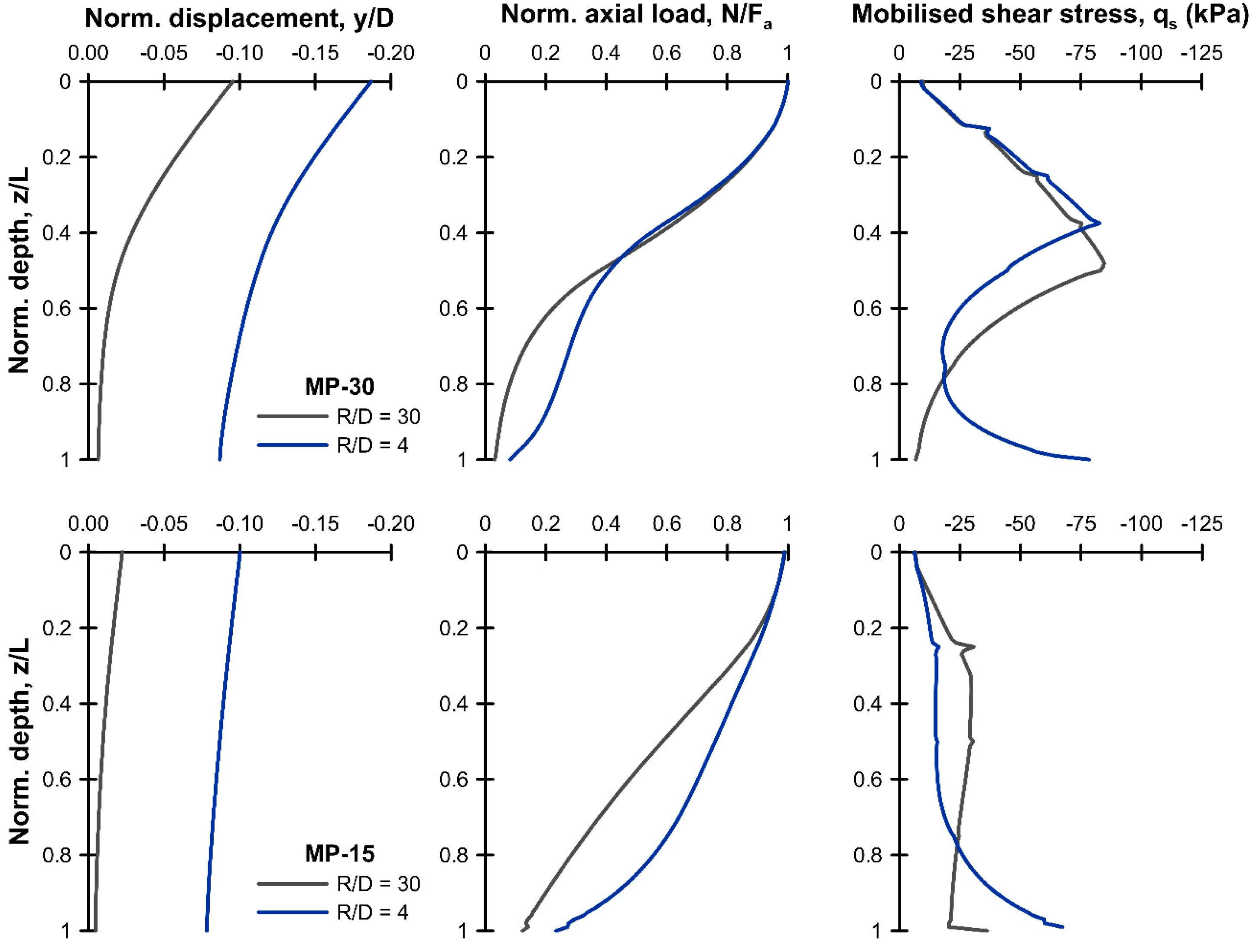
Following the same approach as [34] and [59], amongst others, this study considered group effects through a simple, unit cell approach, adjusting the finite element model radius, R in order to investigate the effect of micropile spacing in mechanical, thermal, and thermo-mechanical pile–soil–pile interactions. Figure 7 illustrates the response of the micropiles under mechanical loading only, but with differing domain radii (R/D = 30 and 4). In this figure, the vertical displacement (y) was normalized by the pile diameter, D, and the axial load (N) by the relevant allowable load, Fa.
The results were broadly as expected, i.e., reduced pile spacing resulted in greater mechanical interference between the piles, leading to increased pile vertical settlement, and changes in the load transfer to the ground with more load passing to the pile base. This pile group interaction effect is well documented and has been described by, e.g., [60,61], among others. Another feature was the increase in mobilized shear stress below about z/L = 0.8, which developed as R/D reduced: this was an additional interference effect which leads to an increase in horizontal stress resulting from load transfer to, and compression of the ground between, the piles in the group, increasing the normal stress acting on the pile shaft.
As noted in the previous section, when R/D = 30 (isolated pile), the mobilization factor, M was 54% and 50% for MP-15 and MP-30, respectively. As R/D reduced to 4, interaction between the piles altered M by a small amount, reducing to 49% and 48%, respectively.

3.2. Thermal Fields for Isolated Pile and Group Unit Cell

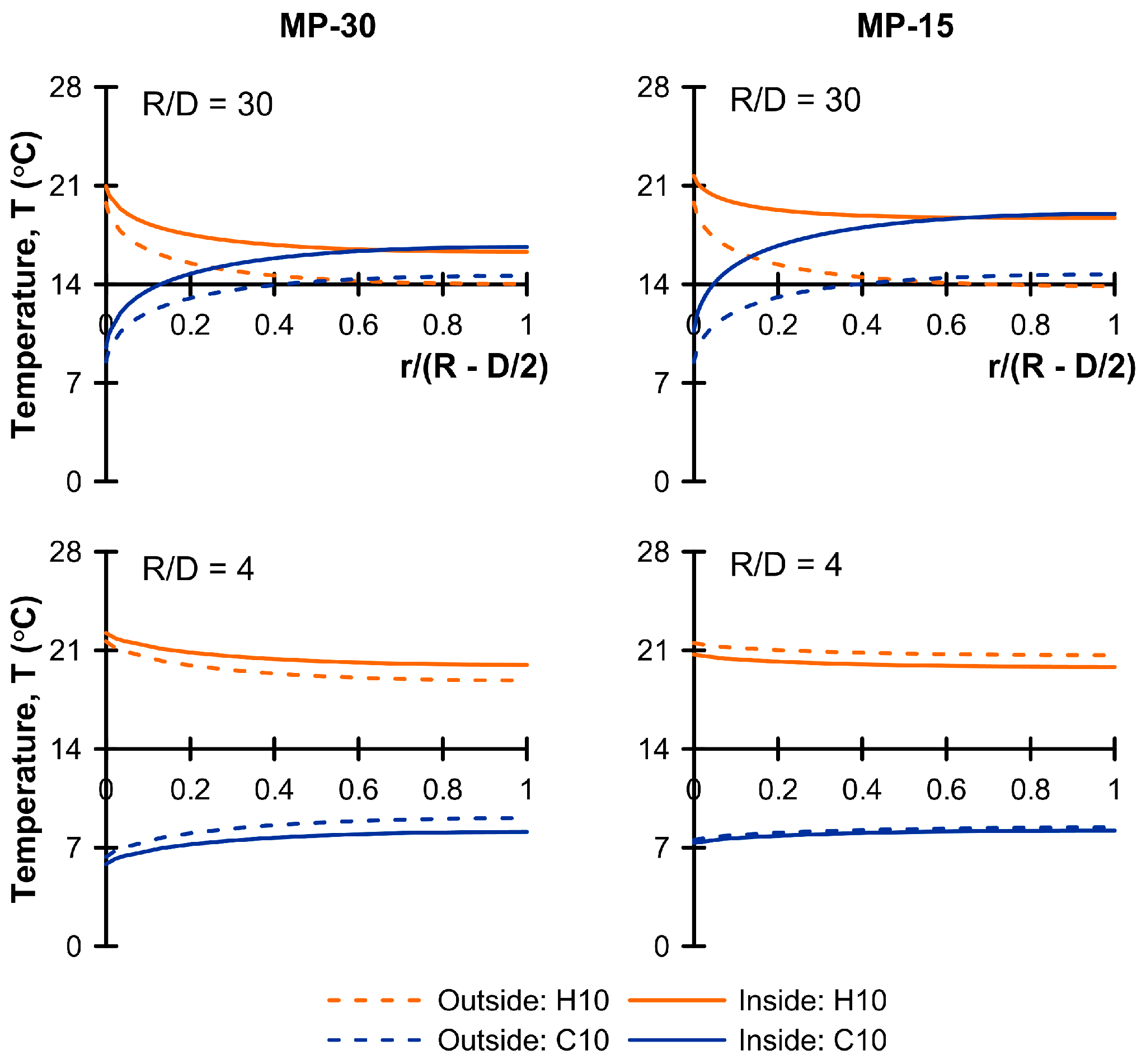
To help in explaining the thermo-mechanical results that follow, Figure 8 illustrates the temperature field at the peak of the last heating and cooling cycle at the mid-depth of the respective piles, and for both the “outside” and “inside” surface temperature boundary conditions. When R/D = 30 (R = 6 m), the temperature interference due to the location of the side boundary was minimal, confirming that the pile may be considered isolated. In the “outside” case, temperatures remained close to 14 °C at distances greater than about 3 m (r/(R − D/2) ≈ 0.5) from the pile face. For the inside case, the effect of pile thermal activation was again seen out to about 3 m, but there was a shift in underlying temperatures to higher values (the average temperature at the surface having risen to 23 °C) with the offset from T0 = 14 °C being larger for MP-15 as the depth for the profile (8.0 m) was shallower than MP-30 (16 m). At closer spacing (R/D = 4), the effect of the surface temperature appears to have been over-ridden by the thermal activation of the micropile, and the entire volume of ground around the micropile closely followed the temperature change imposed in the pile, highlighting an important thermal interference effect that will be discussed subsequently, in terms of the thermo-mechanical response.

3.3. Thermo-Mechanical Behavior

3.3.1. Isolated Micropile and Group Unit Cell Response

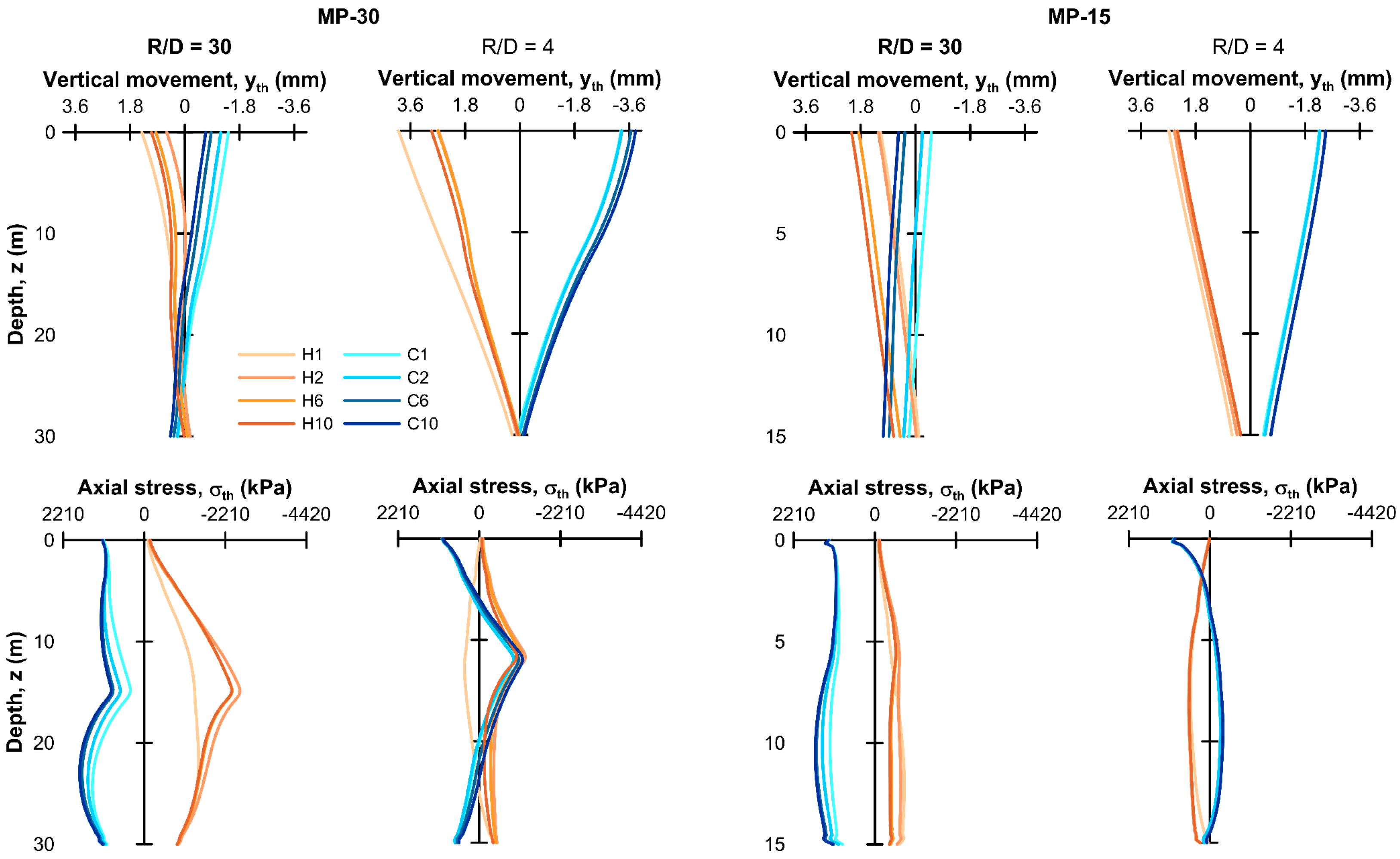
Figure 9 and Figure 10, and Table 3 and Table 4, compare the predicted cyclic thermal response of the micropiles as a function of length (30 and 15 m) and spacing (R/D = 30 and 4), with the “outside” surface temperature boundary condition maintained. For comparison, the free thermal expansion of the pile, yth,free (= αΔT L) was 3.6 and 1.8 mm, for MP-20 and MP-15 respectively, and the maximum thermal stress assuming perfect axial fixity, σth,fixed (=αΔT Ep) was 2210 kPa, where α is the coefficient of linear thermal expansion for the pile (Table 1), ΔT the maximum imposed temperature change (±12 °C), L is the pile length, and Ep is the pile effective stiffness (Table 1).
(a)
Pile axial thermal displacement
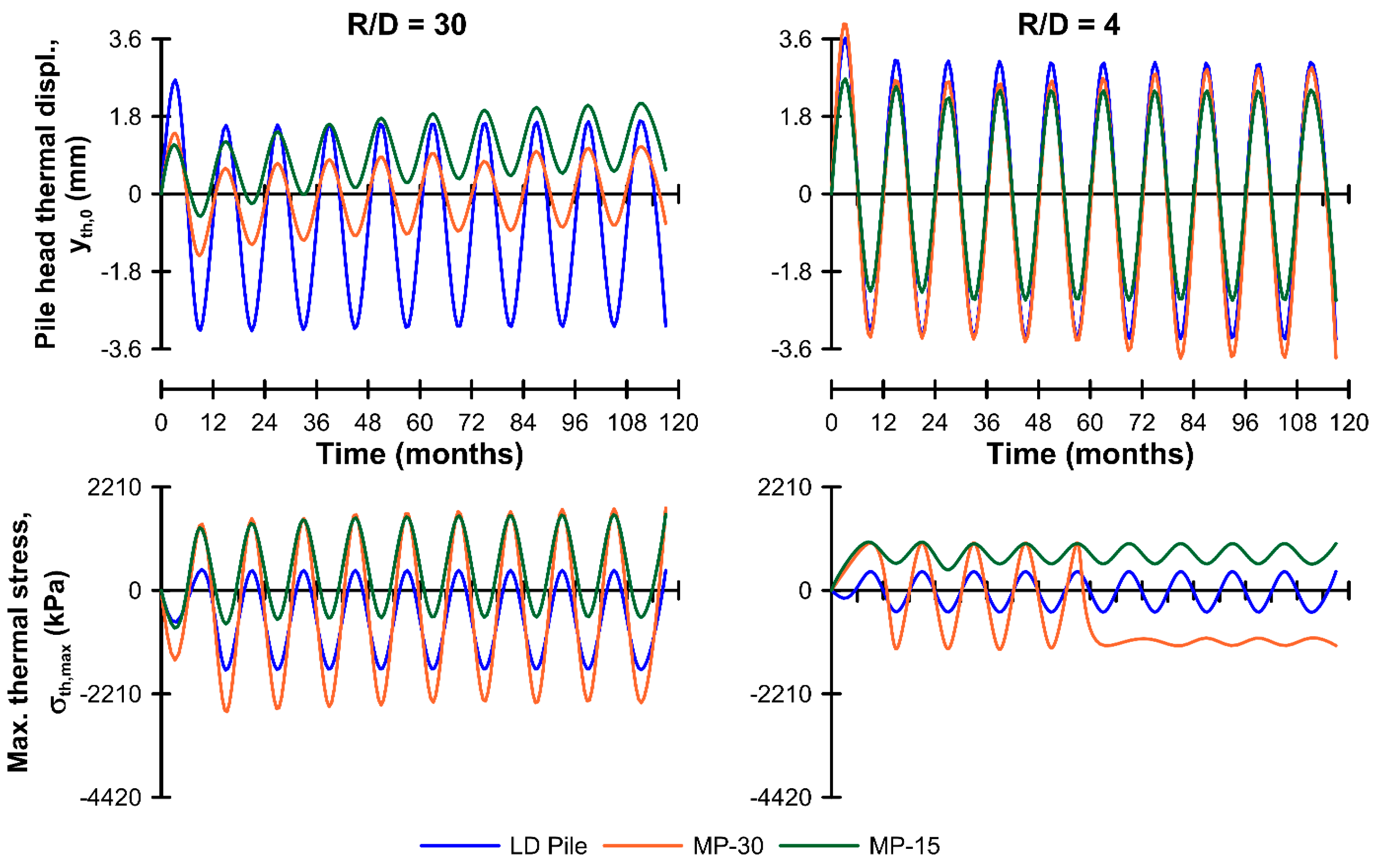
In all cases, a small irrecoverable settlement developed in the first few thermal cycles. For the isolated pile case (R/D = 30), the irrecoverable vertical displacement averaged −1.3 and −0.22 mm for MP-30 and MP-15, respectively, and reduced as R/D (pile spacing) reduced to an average of −0.74 mm and about zero, respectively (Table 3). A cyclic thermo-elastic displacement response developed on top of these irrecoverable settlements: for both isolated pile cases, the amplitude of the movement was about 1 mm but when R/D was reduced to 4, the movement amplitude increased significantly, to 3.2 and 2.5 mm respectively (Table 3). For comparison, the results from the analysis of a 30 m long, LD pile are also in Figure 10; these showed similar behavior, with regular cyclic thermal movements about a small permanent settlement developing in the first few cycles. The permanent movement reduced with reduced pile spacing, but again, the cyclic amplitude increased.
Examining in more detail the response of the two micropile cases, it was observed that during cooling cycles, downwards (negative) axial thermal displacements occurred in all cases, though of differing magnitude—larger downward pile head movements occurred at closer pile spacing which even exceeded yth,free due to the thermal activation of the ground, as discussed in Section 3.2. During heating cycles, there were marked differences which were most obvious for the isolated MP-30 case: here, in the first pile heating, the pile head expanded upwards and the base downwards as expected; in subsequent cycles, however, the upwards expansion was restrained and the resultant thermal movement was downwards (settlement) with respect to the start of the thermal activation of the pile (this effect is further discussed below, in relation to the thermal stress response). At the pile base, on the other hand, the thermal movements were small (± a few tenths of a millimeter, Table 3) and in line with expectations, i.e., downwards during heating and upwards during cooling. This led to significant nonlinearity in the profile of axial thermal movements for the isolated MP-30 case shown in Figure 9a. This effect was still present for MP-30 at R/D = 4 but was much smaller due to the more extensive thermal activation of the surrounding ground. The effect also appeared to be present in the isolated MP-15 case, but due to its shorter length, axial restraint was reduced, and the effect was not so obvious. This response had a direct impact on the axial thermal stress, as will be discussed below.
Finally, considering typical settlement limits for isolated piles and large pile groups, the values of average irrecoverable settlement obtained are unlikely to be of concern in terms of their impact on design. The amplitude of the pile head movement was somewhat larger and may require verification against project serviceability criteria. However, this also needs to be considered in terms of the overall group settlement under external mechanical load only, which was several times larger (see Figure 7), and the thermal movements remained a small proportion of the overall vertical movement which increased as R/D reduced.
(b)
Pile axial thermal stress
The axial deformation responses of the MP-30 and MP-15 cases were discussed above and were directly related to the axial stress response which is also shown in Figure 9 and Figure 10. Here, the thermal stress changes represented around 15 to 20% of the maximum axial stress generated by the mechanical load alone, and the curves are shown in the Figures separately from the mechanical ones. The isolated MP-30 pile exhibited much larger average thermal stress changes than those mobilized in MP-15 (Table 4), in terms of both the average value and amplitude of the thermal stress fluctuations. This was a direct consequence of the strong restraint able to be imposed on pile movements along the shaft, which also acts to lock-in a large compression stress in the first few thermal cycles. In the first heating cycle, the maximum thermal compression stress generated was about two-thirds of σth,fixed, but in the subsequent cycles this more than doubled to about 1.6 σth,fixed. The generation of the large compression stress arose from the low initial shaft resistance mobilization in the lower part of the pile (Figure 7) and from the reversal of shearing on the shaft as the pile expanded upwards in the top half of the pile.
By comparison, the thermal stress generated in cooling cycles was consistent from cycle-to-cycle with the maximum thermal stress (tensile) occurring in the lower third of the pile. The profile of thermal stress along the pile during cooling (Figure 9) was clearly affected by the large locked-in compression stress discussed above, as tensile stress was suppressed in the middle part of the pile. The isolated MP-15 pile showed more typical behavior with the pile expanding and contracting, to generate thermal compression and tensile stress during heating and cooling respectively and with maximum thermal stress changes of less than about 0.5 σth,fixed.
The tensile thermal stress changes discussed above may be of concern in design. However, most micropiles are constructed with full depth reinforcement such as a steel tube, as considered in this study, or a central high-strength steel bar. This means that the micropile is able to carry tensile loads along its full length. Further, in this study, remembering that the piles are in compression due to the mechanical load, the only resultant tensile axial stress occurred for the isolated MP-30 pile and this amounted to only a few-hundred kPa.
For the pile group unit cells (R/D = 4), the MP-15 response was the reverse of the isolated pile (Figure 10), with heating leading to tensile stress due to the thermal activation and expansion of the surrounding soil, and vice versa for cooling. The LD pile did not show this reversal (Figure 10) because of its larger absolute unit cell radius, R = 4 m, compared with 0.8 m on the micropiles and, thus, the more limited thermal activation of the ground. The MP-30 pile response differed markedly from MP-15: while the thermal axial stress reversed in the first heating and all cooling cycles, from the second heating cycle onward, the maximum thermal stress reverted to be a compression irrespective of the heating mode. This would appear to be a similar effect to the isolated piles, in the first cooling cycle, the pile head moved down and when reheated, the soil restraint on the shaft was sufficient to restrain the thermal expansion of the pile and maintain the compression. Over the next few cycles, the effect developed, and only after Year 6 did the pile settlement and compression stress development stabilize. Tension did develop, towards the pile base, however the magnitude of this was always less than the maximum compression.

3.3.2. Influence of Surface Temperature Boundary Condition

Bodas Freitas et al. (2021) [59] examined the effect of an “inside” surface temperature boundary condition on a thermally-activated large diameter pile in a cohesive medium, by introducing a periodic function similar to that described in Section 2.3. They found that tension was generated at the pile head, but this stabilized after a number of seasonal cycles and the overall effect in terms of pile head thermal movement and axial thermal load was similar to the case where the “outside” condition was maintained. Figure 11 and Figure 12, and Table 5 and Table 6, present and summarize the results of a similar assessment for the two micropile configurations considered in this study.
(a)
MP-15
In the isolated MP-15 case (R/D = 30), the amplitude of the pile head movement and thermal stress changes were very similar to the outside case. The average pile head thermal movements, however, moved from a small settlement to an upward movement of about 1.3 mm (0.7yth,free) at the end of 10 years, which continued to accumulate (Figure 12). Associated with this, the axial thermal stress became tensile on average with a 525 kPa tension compared with about 150 kPa compression in the MP-15 “outside” case.
In the group unit cell (R/D = 4) case, there was little change in the displacement response from the “outside” to the “inside” condition, other than the base of the pile settling a small amount in the “inside” case. However, the axial thermal stress increased on average from a tension of 80 kPa to 780 kPa while the stress amplitude approximately halved. This apparent reduction in amplitude was due to the compression generated during cooling by the contraction of the pile and soil (about 350 kPa), being dominated by a tension (about 1000 kPa) that was generated at the pile head, Figure 11.
(b)
MP-30
In the isolated MP-30 “inside” case, the amplitude of pile head movement and thermal stress changes were broadly similar to those for the “outside” case, while the averages moved upwards and became less compressive over time, respectively, in a similar way to MP-15. Average pile head thermal movements moved from a small settlement in the first cycle, to a small heave (0.1 mm), while the movement amplitude was about ±1 mm. The associated thermal stress amplitudes remained similar to the “outside” case and the average thermal stress reduced by about two-thirds but remained in compression.
In the group unit cell scenario, the response was also broadly similar to the “outside” case. A small pile head settlement occurred in the first few cycles which was not matched by pile base settlement, and this differential movement between the pile head and base (elastic shortening) resulted in a locked-in compression stress which later thermal cycles were not able to overcome.
Irrespective of the pile length and pile spacing (R/D), in cooling, a significant tensile load was generated close to the pile head which largely disappeared during heating cycles. This occurred as a result of the warming of the upper profile under the new surface boundary condition which was antagonistic to the effects generated by pile cooling, i.e., the ground expanding up and the pile contracting down. However, during heating, the effects were complementary as the soil and pile expanded together.
Again, the generation of tensile thermal stress could be of concern but only if the combined thermo-mechanical stress response became tensile. For example, in this case, the thermal tension generated at the pile head ranged between about 30 and 40 kN, while the initial mechanical load was a compression of 235 kN and 765 kN for MP-15 and MP-30, respectively. Similarly, elsewhere, despite tensile thermal stress developing, the resultant axial stress remained in compression, even at the pile base, e.g., in the MP-30 R/D = 4 case, a thermal tension of about 17 kN was predicted, however, the pile base reaction under mechanical load was 68 kN. This highlights another mitigating effect of close pile spacing in groups which leads to additional load (compression) being transferred to the pile base, prior to any thermal effects being superimposed. As noted previously, micropiles are usually constructed with full-length reinforcement, so even if a resultant tension developed, this would not be detrimental to performance.

3.4. Heat Transfer

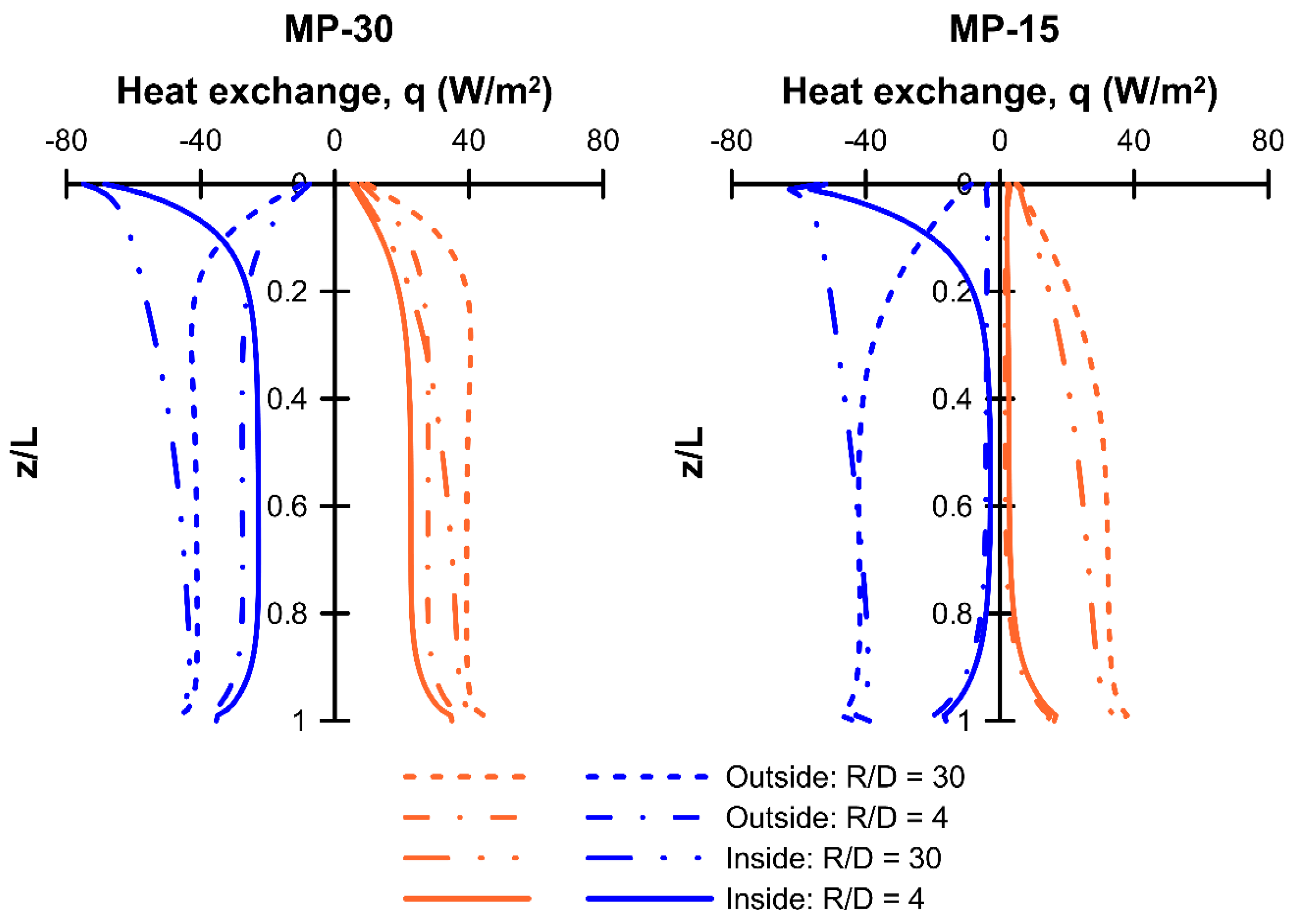
Figure 13 and Table 7 illustrate the effect of micropile spacing and surface temperature boundary condition on the heat exchange potential, at the peak of the tenth heat injection and extraction seasons. It can be noted that the heat exchange in earlier cycles was within about 10% of the values shown. The values indicated in Table 7 are the total heat flow averaged over the length of the pile. These absolute values of heat exchange should be treated as illustrative only, as the full heat transfer process (e.g., fluid flow within and the heat exchange pipes, etc.) has not been modeled. For comparison, the values for R/D = 30 in Table 7 are about half of the heat exchange values suggested by Brandl (2006) [2]. The relative effects created by the variations considered are of interest, however.
When the “inside” surface temperature condition was applied, heat injection was reduced and heat extraction was enhanced, with respect to that for the “outside” condition, due to the general warming imposed in the ground around the micropiles, directly below the overlying structure, see Figure 8.
The effect of pile–pile thermal interference is apparent, with total heat exchange and the difference between “outside” and “inside” conditions reducing as R/D reduced. Heat exchange became practically null for MP-15 when R = 0.8 m. In practice, micropiles tend to be used in groups with close absolute spacing (even if the relative spacing is large), so the conditions that lead to the apparent loss of heat transfer efficiency will be the subject of further study, to define how to optimize the distribution of TA micropiles within foundations.

3.5. Comparison with Previous Studies

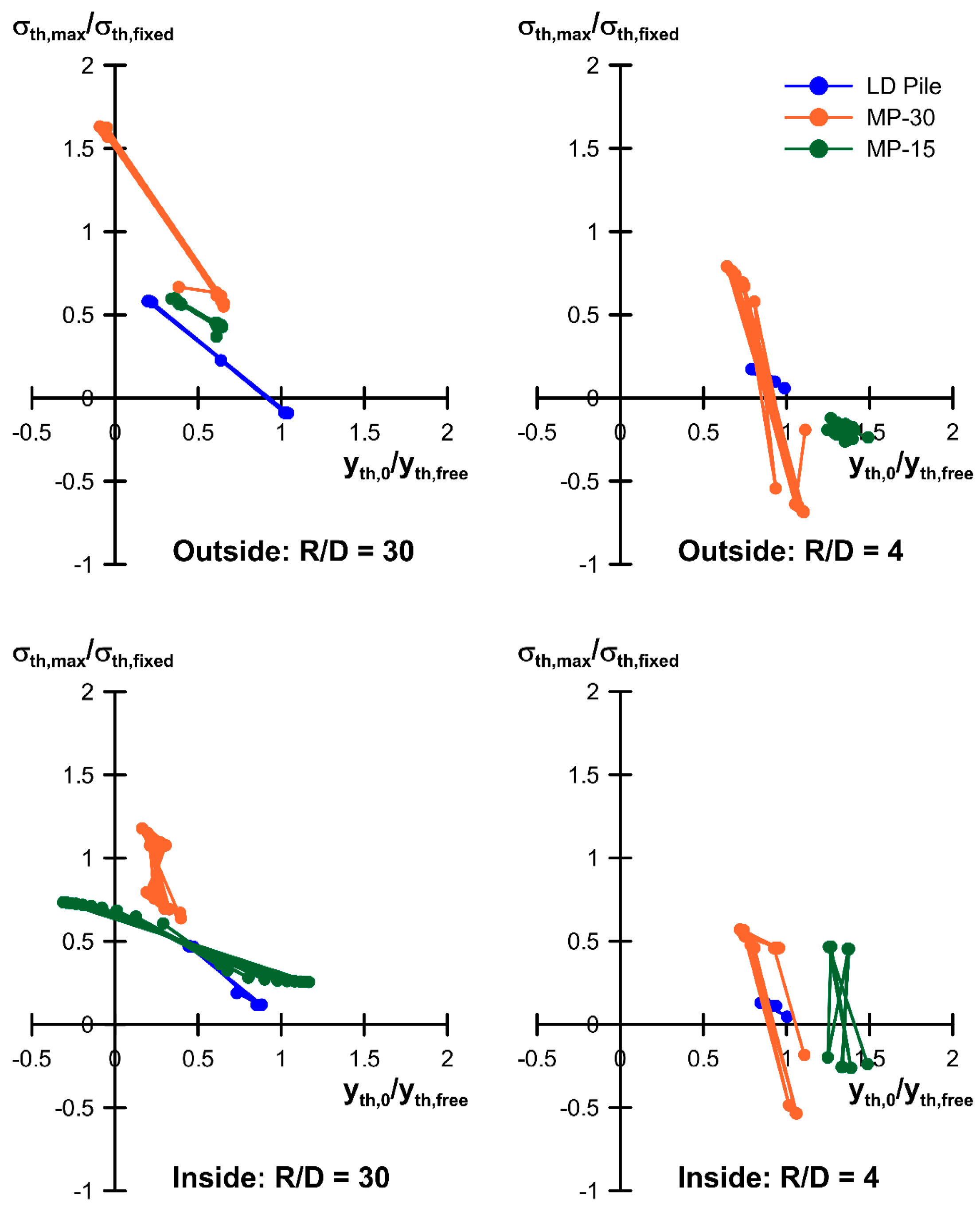
In related studies, Bourne-Webb et al. (2022b) [62] and Bodas Freitas et al. (2021) [59] examined the behavior of LD piles in frictional and cohesive media, respectively. In both studies, it was demonstrated that the degree of initial mobilization of the shaft resistance, M, controlled the subsequent cyclic thermal response. They concluded that in these cases, the cyclic thermal response was largely stable for values of M less than about 80% to 90% (Bourne-Webb et al., 2022b) [62]. Figure 14 compares the normalized thermal stress-displacement response of the reported behavior of LD piles in frictional media (Bourne-Webb et al., 2022a) [34] and the micropiles from this study. Following Bourne-Webb et al. (2022a) [34] and Juran et al. (1999) [56], the pile head thermal displacement, yth,0, and the maximum axial thermal stress, σth,max, were normalized by the theoretical values for unrestrained pile expansion, yth,free, and the thermal stress due to perfect restraint, σth,fixed, respectively (as defined in Section 3.3.1). When normalization is positive, this means that the stress/displacement changes are in the same sense, i.e., compression and expansion upwards during pile heating, and vice versa.
(a)
Isolated piles (R/D = 30)
Despite the differences in physical dimensions, pile stiffness and M-values (50 to 70% but less than 80%), the piles showed similar behavior in terms of the thermal stress-displacement response with an increase in stress as pile head movement reduced, and vice versa, which was qualitatively similar to that observed in field tests of isolated piles (Bourne-Webb et al., 2019) [63]. Even MP-30, where the response was conditioned somewhat by the slenderness of the pile and its low relative axial stiffness compared with the other cases, fell into the same pattern of behavior, although with rather larger thermal stresses.
(b)
Pile group (unit cell with R/D = 4)
For the three cases illustrated, the group effect was similar, with a reduction in thermal stress associated with an increase in average thermal pile head movement. However, the general trend in the stress-displacement response was maintained.
It should be noted that it is expected that when micropiles are used with a higher initial mobilization of the shaft resistance, which might be the case when they are used for settlement control, then the cyclic thermal response may follow that seen in previous studies of large diameter piles, with the potential for significant irrecoverable settlement developing. Therefore, the thermal activation of piles used to stabilize and limit the settlements of existing foundations will require careful consideration.
In terms of heat transfer, the relative effect between the LD pile and micropile cases is for a reduction. This follows the suggestion by Brandl (2006) [2], that heat transfer values suitable for preliminary design of small diameter piles (0.3 to 0.5 m diameter) are 55 to 65% less than those for a 1 m diameter pile, indicating at least a similar relative effect of pile dimension on the heat transfer.

4. Conclusions

There is a lot of interest in the potential for incorporating shallow geothermal energy systems within building retrofits, with one of the key concerns for this application being how to provide cost effective and efficient ground coupling.
The work presented here addresses the possible use of thermally-activated micropiles for this purpose, and specifically, how cyclic thermal loading impacts on the pile load-transfer performance. In the work presented, a single micropile was analyzed with a simplified numerical model in terms of the ground profile and soil material behavior, and the effect of pile–soil–pile interaction within groups of micropiles was examined based on a unit cell approach (by reducing the radius of the analysis domain). Based on the work presented, the following observations and conclusions have been drawn:
  • At the applied service load, which was based on a factor of safety of 2 on shaft resistance, the mobilization factor, M, describing the proportion of shaft resistance mobilized relative to the maximum available shaft resistance, was around 50%. In the cases involving reduced pile spacing, the pile–soil–pile interactions led to M reducing further by about 5%. In an associated study examining large diameter piles, it was established that having M less than 80% was necessary to ensure the response to thermal loading was quasi thermo-elastic;
  • Under cyclic thermal loading, an irrecoverable settlement developed in the first few cycles; the values were small, however, and are unlikely to be important in design terms. This initial settlement occurred in the first cooling cycles and was due to reductions in horizontal stress and, thus, available shaft resistance, as the pile contracted. The mobilized shaft and base resistances quickly adjusted to rebalance this effect and subsequent pile head displacements were thermo-elastic. The associated thermal stress changes also quickly stabilized having been modified by the initial alterations in the mobilized shaft and base resistance, discussed above. This stable response was due to the low initial mobilization (M < 50%) of the available shaft resistance;
  • This study highlights another important issue related to the slenderness and axial stiffness of the TA pile; in this case, the initial response of the micropile to the thermal cycles resulted in large compression stresses being locked-in, which in the case of an isolated pile, led to stresses in excess of the value for perfect thermal restraint—in this case, about 60% higher. This effect should be carefully considered when long, slender TA piles are planned to be used;
  • The results presented from this study illustrate the potential for using micropiles in SGE systems. It is clear that with a design based only on the shaft resistance and factors of safety typically used for micropile design (around 2.0), the thermo-mechanical response should be stable in the long term. Again, if long, slender piles are to be used, then attention should be paid to the thermal stress changes that could develop and, in all cases, especially in closely spaced groups, cyclic pile head movements should be verified against the allowable movement limits specified for the project. These findings are not applicable for micropiles used as settlement reducing type piles, with high initial mobilization of the available shaft resistance;
  • The introduction of a surface temperature boundary condition representing an air-conditioned building supported by a pile foundation, resulted in an axial thermal tension load developing at the pile head and elsewhere within the pile body. This was due to the general warming of the ground near the surface which created an underlying tensile response, onto which was superimposed additional thermal tension due to cyclic thermal operation of the micropile. In the cases studied here however, at no time did the pile thermo-mechanical axial stress stray into tension;
  • Heat exchange for cooling was found to be compromised by the surface boundary condition imposed by a climate-controlled structure supported by the piles, while heating potential was enhanced as the heat losses from the overlying structure were “recycled”. Absolute pile spacing is also important for heat exchange potential, as thermal interference leads to reduced potential in closely spaced piles, and at the closest spacing considered herein, resulted in a significant loss of function. This is an issue that requires further study, to optimize TA micropile layouts to ensure correct functioning of the SGE system.

Author Contributions

Conceptualization, P.J.B.-W. and T.M.B.F.; methodology, A.L., P.J.B.-W. and T.M.B.F.; formal analysis and investigation, A.L., P.J.B.-W., T.M.B.F. and D.S.; writing—original draft preparation, P.J.B.-W.; writing—review and editing, A.L., T.M.B.F. and D.S.; resources, CERIS and University of Perugia; supervision, P.J.B.-W., T.M.B.F. and D.S.; visualization, A.L., D.S. and P.J.B.-W. All authors have read and agreed to the published version of the manuscript.

Funding

The work presented was undertaken as part of the project DEEPCOOL (PTDC/ECI-EGC/29083/2017) financed by the Fundação para a Ciência e a Tecnologia (FCT), Portugal. FCT also supports the research unit CERIS through grant no. UIDB/04625/2020. The first author undertook the work presented here while studying at Instituto Superior Técnico, as part of an ERASMUS+ traineeship.

Institutional Review Board Statement

Not applicable.

Informed Consent Statement

Informed consent was obtained from all subjects involved in the study.

Data Availability Statement

Data sets generated during the current study are available from the corresponding author on reasonable request.

Acknowledgments

The authors would like to express their gratitude to the funding institutions for their support.

Conflicts of Interest

The authors confirm that there are no conflict of interest issues associated with this article. All co-authors are aware of and have contributed to the work described in the article, including its drafting and revision.

References

  1. Cotana, F.; Belardi, P.; Manciola, P.; Tamagnini, C.; Materazzi, A.L.; Fornaciari, M.; Petrozzi, A.; Pisello, A.L.; Cavalaglio, G.; Coccia, V.; et al. TIAR: Renewable energy production, storage and distribution; a new multidisciplinary approach for the design of rural facility. Energy Procedia 2014, 45, 323–332. [Google Scholar] [CrossRef]
  2. Brandl, H. Energy foundations and other thermo-active ground structures. Géotechnique 2006, 56, 81–122. [Google Scholar] [CrossRef]
  3. Di Donna, A.; Barla, M.; Amis, T. Energy Geostructures: Analysis from Research and Systems Installed around the World. In Proceedings of the 42nd Annual Conerence. on Deep Foundations, New Orleans, LA, USA, 24–27 October 2017. [Google Scholar]
  4. Bernardi, A.; Pockelé, L.; Sanner, B.; Cicolin, F.; De Carli, M.; Galgaro, A.; Urchueguía, J.; Mezzasalma, G.; Pasquali, R.; Poletto, F.; et al. Innovative drilling methods, heat pumps and tools to address shallow geothermal in the built environment: H2020 project—GEO4CIVHIC. In Proceedings of the European Geothermal Conference, Den Haag, The Netherlands, 11–14 June 2019. [Google Scholar]
  5. Uotinen, V.M.; Repo, T.; Vesamäki, H. Energy piles—Ground energy system integrated to the steel foundation piles. In Proceedings of the 16th Nordic Geotechnical Meeting, Copenhagen, Denmark, 9–12 May 2012. [Google Scholar]
  6. Tyszer, M.; Tomaszewska, B. Evaluation of the Possibility of Use Geothermal Energy Micropiles TITAN 73/53 to Obtain Low-Temperature Heat Energy Accumulated in the Near-Surface Layers of the Ground in Poland Area. In Renewable Energy Sources: Engineering, Technology, Innovation; Mudryk, K., Werle, S., Eds.; Springer Proceedings in Energy; Springer: Cham, Germany, 2018. [Google Scholar]
  7. Lautkankare, R.; Sarola, V.; Kanerva-Lehto, H. Energy piles in underpinning projects—Through holes in load transfer structures. J. Deep. Found. Inst. 2014, 8, 3–14. [Google Scholar] [CrossRef]
  8. EN 14199:2005; Execution of Special Geotechnical Works-Micropiles. BSI: London, UK, 2005.
  9. Bruce, D.A.; Dimillio, A.; Juran, I. Micropiles: The state of practice. Part I: Characteristics, definitions and classifications. Ground Improv. 1997, 1, 25–35. [Google Scholar] [CrossRef]
  10. Lizzi, F. “Pali radice” structure. In Underpinning and Retention; Thorburn, S., Littlejohn, G.S., Eds.; Blackie Academic & Professional: Glasgow, UK, 1993. [Google Scholar]
  11. Rotta Loria, A.F.; Vadrot, A.; Laloui, L. Analysis of the vertical displacement of energy pile groups. Geomech. Energy Environ. 2018, 16, 1–14. [Google Scholar] [CrossRef]
  12. Mohamad, Z.; Fardoun, F.; Meftah, F. A review on energy piles design, evaluation, and optimization. J. Clean. Prod. 2021, 292, 125802. [Google Scholar] [CrossRef]
  13. Liu, S.W.; Zhang, Q.Q.; Cui, W.; Liu, G.H.; Liu, J.H. A simple method for analyzing thermomechanical response of an energy pile in a group. Geomech. Energy Environ. 2022, 32, 100309. [Google Scholar] [CrossRef]
  14. Lupattelli, A.; Cernuto, E.; Brunelli, B.; Cattoni, E.; Salciarini, D. Experimentation of the Thermo-Mechanical Behavior of the Soil-Concrete Interface. In Springer Series in Geomechanics and Geoengineering; Springer: Berlin/Heidelberg, Germany, 2023; pp. 343–350. [Google Scholar]
  15. Salciarini, D.; Cecinato, F. Numerical Modelling of Thermo-active Micropiles. Lect. Notes Civ. Eng. 2021, 126, 1102–1109. [Google Scholar]
  16. Gerola, M.; Lupattelli, A.; Cecinato, F.; Salciarini, D.; Arola, T. Numerical Analysis of the Behaviour of Energy Micropiles Used for Heat Storage: A Case Study in Turku (Finland). In Springer Series in Geomechanics and Geoengineering; Springer: Berlin/Heidelberg, Germany, 2023; pp. 808–815. [Google Scholar]
  17. Akrouch, G.A.; Sánchez, M.; Briaud, J.L. Thermo-mechanical behavior of energy piles in high plasticity clays. Acta Geotech. 2014, 9, 399–412. [Google Scholar] [CrossRef]
  18. Alberdi-Pagola, M.; Lund Jensen, R.; Erbs Poulsen, S. A performance case study of energy pile foundation at Rosborg Gymnasium (Denmark), in CLIMA 2016. In Proceedings of the 12th REHVA World Congress, Aalborg, Denmark, 22–25 May 2016. [Google Scholar]
  19. Hamada, Y.; Saitoh, H.; Nakamura, M.; Kubota, H.; Ochifuji, K. Field performance of an energy pile system for space heating. Energy Build. 2007, 39, 517–524. [Google Scholar] [CrossRef]
  20. Jalaluddin, J.; Miyara, A.; Tsubaki, K.; Yoshida, K. Thermal performances of three types of ground heat exchangers in short-time period of operation. In Proceedings of the International Refrigeration and Air Conditioning Conference, West Lafayette, IN, USA, 12–15 July 2010. [Google Scholar]
  21. Katsura, T.; Nakamura, Y.; Okawada, T.; Saeki, E.; Nakamura, Y.; Okamoto, A.; Narita, S. Field test on heat extraction or injection performance of energy piles and its application. In Proceedings of the 11th International Conference on Thermal Energy Storage, Stockholm, Sweden, 14–17 June 2009. [Google Scholar]
  22. Nagano, K.; Katsura, T.; Takeda, S.; Saeki, E.; Nakamura, Y.; Okamoto, A.; Narita, S. Thermal characteristics of steel foundation piles as ground heat exchangers. In Proceedings of the 8th IEA Heat Pump Conference, Las Vegas, NV, USA, 30 May–2 June 2005. [Google Scholar]
  23. Ronchi, F.; Salciarini, D.; Cavalagli, N.; Tamagnini, C. Thermal response prediction of a prototype Energy Micro-Pile. Geomech. Energy Environ. 2018, 16, 64–82. [Google Scholar] [CrossRef]
  24. Ren, L.-W.; Xu, J.; Kong, G.Q.; Liu, H.L. Field tests on thermal response characteristics of micro-steel-pipe pile under multiple temperature cycles. Renew. Energy 2020, 147, 1098–1106. [Google Scholar] [CrossRef]
  25. Kong, G.; Cao, T.; Hao, Y.; Zhou, Y.; Ren, L. Thermomechanical properties of an energy micro pile-raft foundation in silty clay. Undergr. Space 2019, 6, 76–84. [Google Scholar] [CrossRef]
  26. Alberdi-Pagola, M.; Madsen, S.; Lund Jensen, R.; Erbs Poulsen, S. Numerical investigation on the thermo-mechanical behavior of a quadratic cross section pile heat exchanger. In Proceedings of the IGSHPA Technical/Research Conference and Expo, Denver, CO, USA, 14–16 March 2017. [Google Scholar]
  27. Hassani Nezhad Gashti, E.; Uotinen, V.M.; Kujala, K. Numerical modelling of thermal regimes in steel energy pile foundations: A case study. Energy Build. 2014, 69, 165–174. [Google Scholar] [CrossRef]
  28. Hassani Nezhad Gashti, E.; Uotinen, V.M.; Kujala, K. Evaluation of thermo-mechanical behaviour of composite energy piles during heating/cooling operations. Eng. Struct. 2014, 75, 363–373. [Google Scholar] [CrossRef]
  29. Skordas, D.; Bodas Freitas, T.M.; Borne-Webb, P.J.; Georgiadis, K. Modelling of thermally-activated bored micropiles for provision of renewable heating & cooling in buildings. In Proceedings of the International Conference on Construction, Energy, Environment & Sustainability, Coimbra, Portugal, 12 October 2021. [Google Scholar]
  30. Bourne-Webb, P.J. Observed Response of Energy Geostructures. In Energy Geostructures; Laloui, L., Di Donna, A., Eds.; John Wiley & Sons, Inc.: Hoboken, NJ, USA, 2013. [Google Scholar]
  31. Loveridge, F.; McCartney, J.S.; Narsilio, G.A.; Sanchez, M. Energy geostructures: A review of analysis approaches, in situ testing and model scale experiments. Geomech. Energy Environ. 2020, 22, 100173. [Google Scholar] [CrossRef]
  32. Cecinato, F.; Salciarini, D. Energy performance assessment of thermo-active micro-piles via numerical modeling and statistical analysis. Geomech. Energy Environ. 2021, 29, 100268. [Google Scholar] [CrossRef]
  33. Garbellini, C.; Laloui, L. Thermal stress analysis of energy piles. Géotechnique 2019, 71, 260–271. [Google Scholar] [CrossRef]
  34. Bourne-Webb, P.J.; Lupattelli, A.; Bodas Freitas, T.M.; Salciarini, D. The influence of initial shaft resistance mobilisation in the response of seasonally thermally-activated pile foundations in granular media. Geomech. Energy Environ. 2022, 30, 100299. [Google Scholar] [CrossRef]
  35. ABAQUS Simulia, Abaqus 2016 Software Documentation; Dassault Systèmes; Dassault Systèmes Simulia Corp.: Providence, RI, USA, 2016.
  36. Zito, M. Transient Analysis of Building-Pile-Soil Interactions in Thermally-Activated Foundations. Master’s Thesis, Civil Engineering, Politecnico di Milano, Milano, Italy, 2019. [Google Scholar]
  37. Jenck, O.; Dias, D.; Kastner, R. Three-Dimensional Numerical Modeling of a Piled Embankment. Int. J. Geomech. 2009, 9, 102–112. [Google Scholar] [CrossRef]
  38. Tschuchnigg, F.; Schweiger, H.F. Comparison of Deep Foundation Systems using 3D Finite Element Analysis Employing Different Modeling Techniques. Geotech. Eng. J. SEAGS AGSSEA 2013, 44, 40–46. [Google Scholar]
  39. Ng, K.S.; Tan, S.A. Stress Transfer Mechanism in 2D and 3D Unit Cell Models for Stone Column Improved Ground. Int. J. Geosynth. Ground Eng. 2014, 1, 3. [Google Scholar] [CrossRef]
  40. Barker, C.A. Behaviour of sand: An Investigation of Bochum Sand. Master’s Thesis, Imperial College, London, UK, 2001. [Google Scholar]
  41. Leroueil, S.; Hight, D.W. Behaviour and Properties of Natural Soils and Soft Rocks. In Characterisation and Engineering Properties of Natural Soils; CRC Press: London, UK, 2003. [Google Scholar]
  42. Jefferies, M.G.; Shuttle, D.A. NORSAND—Features Calibration & Use. In Soil Constitutive Models: Evaluation, Selection, and Calibration; GSP 128; American Society of Civil Engineers: Reston, VA, USA, 2005; pp. 204–236. [Google Scholar]
  43. Gawecka, K.A.; Taborda, D.M.G.; Potts, D.M.; Cui, W.; Zdravkovi, L.; Kasri, M.S.H. Numerical modelling of the thermos-active piles in London Clay. ICE Proc. Geotech. Eng. 2017, 170, 201–219. [Google Scholar] [CrossRef]
  44. Rotta Loria, A.F.; Donna, A.D.; Laloui, L. Numerical Study on the Suitability of Centrifuge Testing for Capturing the Thermal-Induced Mechanical Behavior of Energy Piles. J. Geotech. Geoenviron. Eng. 2015, 141, 04015042. [Google Scholar] [CrossRef]
  45. Rotta Loria, A.F.; Gunawan, A.; Shi, C.; Laloui, L.; Ng, C.W.W. Numerical Modelling of Energy Piles in Saturated Sand Subjected to Thermo-Mechanical Loads. Geomech. Energy Environ. 2015, 1, 1–15. [Google Scholar] [CrossRef]
  46. Han, J.; Liu, L.; Zuo, C.; Wang, H.; Lin, F.; Zhao, Y.; Li, T.; Liu, D. Evolution and Parametric Analysis of Concrete Temperature Field Induced by Electric Heating Curing in Winter. Sustainability 2023, 15, 8337. [Google Scholar] [CrossRef]
  47. Naus, D.J. A Compilation of Elevated Temperature Concrete Material Property Data and Information for Use in Assessments of Nuclear Power Plant Reinforced Concrete Structures; (No. ORNL/TM-2009/175); Oak Ridge National Laboratory: Oak Ridge, TN, USA, 2010. [Google Scholar]
  48. Allan, M.L.; Philippacopoulos, A.J. Thermally Conductive Cementitious Grouts for Geothermal Heat Pumps. Progress Report FY 1998; (Informal No. BNL-66103); Brookhaven National Laboratory: Upton, NY, USA, 1998. [Google Scholar]
  49. Lim, J.K.; Lehane, B. Shearing resistance during pile installation in sand. ICE Proc. Geotech. Eng. 2015, 168, 168–235. [Google Scholar] [CrossRef]
  50. Vieira, A.; Alberdi-Pagola, M.; Barla, M.; Christodoulides, P.; Florides, G.; Insana, A.; Javed, S.; Maranha, J.; Milenic, D.; Prodan, I.; et al. Site characterization for the design of thermoactive geostructures. Soils Rocks 2022, 45, e2022001022. [Google Scholar] [CrossRef]
  51. Fleming, W.G.K. Piling Engineering, 3rd ed.; Taylor & Francis: London, UK; New York, NY, USA, 2009. [Google Scholar]
  52. Fuentes, R.; Pinyol, N.; Alonso, E. Effect of temperature induced excess porewater pressures on the shaft bearing capacity of geothermal piles. Geomech. Energy Environ. 2016, 8, 30–37. [Google Scholar] [CrossRef]
  53. Joshaghani, M.; Ghasemi-Fare, O. Exploring the effects of temperature on intrinsic permeability and void ratio alteration through temperature-controlled experiments. Eng. Geol. 2021, 293, 106299. [Google Scholar] [CrossRef]
  54. Tatro, S.B. Thermal Properties (of Concrete). In Significance of Tests and Properties of Concrete and Concrete-making Materials; Lamond, J.F., Pielert, J.H., Eds.; ASTM International: West Conshohocken, PA, USA, 2006; pp. 226–237. [Google Scholar]
  55. Côté, J.; Konrad, J.-M. A Generalized Thermal Conductivity Model for Soils and Construction Materials. Can. Geotech. J. 2005, 42, 443–458. [Google Scholar] [CrossRef]
  56. Juran, I.; Bruce, D.A.; Dimillio, A.; Benslimane, A. Micropiles: The state of practice. Part II: Design of single micropiles and groups and networks of micropiles. Ground Improv. 1999, 3, 89–110. [Google Scholar] [CrossRef]
  57. FHWA. Micropile Design and Construction; Publ. No. FHWA NHI-05-039; National Highway Institute: Washington, DC, USA, 2005. [Google Scholar]
  58. BS EN 1997-1:2004+A1:2013; Eurocode 7. Geotechnical Design—General Rules. BSI: London, UK, 2005.
  59. Bodas Freitas, T.M.; Zito, M.; Bourne-Webb, P.J.; Sterpi, D. Thermal performance of seasonally, thermally-activated floating pile foundations in a cohesive medium. Eng. Struct. 2021, 243, 112588. [Google Scholar] [CrossRef]
  60. Poulos, H.G. Analysis of the settlement of pile groups. Géotechnique 1968, 18, 449–471. [Google Scholar] [CrossRef]
  61. Poulos, H.G. Group factors for pile-deflection estimation. ASCE J. Geotech. Eng. Div. 1979, 105, 1489–1509. [Google Scholar] [CrossRef]
  62. Bourne-Webb, P.J.; Bodas Freitas, T.M.; Zito, M.; Lupattelli, A.; Sterpi, D.; Salciarini, D. Outstanding issues in understanding the behaviour of thermally-activated pile foundations. In Proceedings of the DFI EFFC International Conference on Deep Foundations and Ground Improvements, Berlin, Germany, 18–20 May 2022. [Google Scholar]
  63. Bourne-Webb, P.J.; Bodas Freitas, T.M.; Freitas Assunção, R.M. A review of pile-soil interactions in isolated, thermally-activated piles. Comput. Geotech. 2019, 108, 61–74. [Google Scholar] [CrossRef]
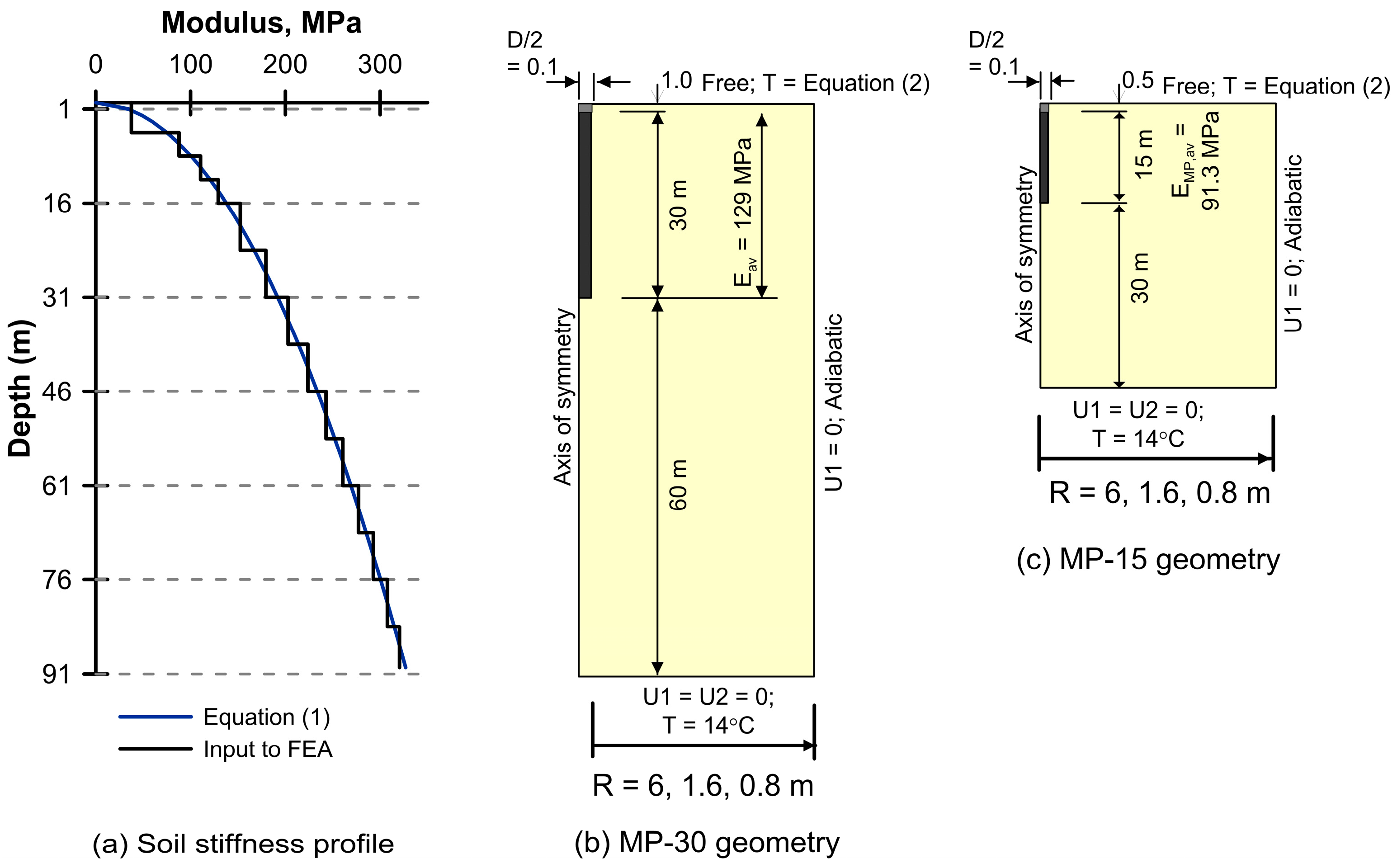
Figure 1. (a) Profile of soil stiffness; (b) Large Diameter (LD) pile geometry and boundary conditions; (c) Micropile (MP) geometry and boundary conditions (U1: horizontal fixity, U2: vertical fixity, T: temperature).
Applsci 13 09791 g001
Figure 2. FE 2D model with the details of the adopted structured spatial discretization.
Applsci 13 09791 g002
Figure 3. (a) Seasonal surface temperature boundary conditions applied, and (b) development of initial temperature profile.
Applsci 13 09791 g003
Figure 4. Pile load-displacement response predicted by numerical analysis and allowable service loads defined for micropiles MP-30 and MP-15 (left) and the LD pile (right).
Applsci 13 09791 g004
Figure 5. Mobilized pile–soil interface shear stress at allowable and ultimate axial loads for the case: (a) 15 m micropile; (b) 30 m micropile; (c) large diameter pile.
Applsci 13 09791 g005
Figure 6. Comparison of MP and LD pile response under allowable load conditions.
Applsci 13 09791 g006
Figure 7. Effect of pile proximity in unit cell groups, on the initial mechanical load transfer response along the pile axis (y/D and N/Fa) and on the pile–soil contact (qs).
Applsci 13 09791 g007
Figure 8. Radial temperature variation at mid-depth of micropiles (z/L = 0.5) from cycle No. 10 at peak heating and peak cooling, MP-30 top, and MP-15 bottom.
Applsci 13 09791 g008
Figure 9. Profiles of pile axial thermal movement (yth) and stress (σth) over 10 cycles of balanced thermal loading for an isolated pile (R/D = 30) and a pile group (R/D = 4) with outside surface temperature boundary condition.
Applsci 13 09791 g009
Figure 10. Effect of pile proximity on cyclic thermal axial load-transfer response of micropile unit cell groups.
Applsci 13 09791 g010
Figure 11. Profiles of pile thermal vertical displacement, axial stress, and pile–soil interface shear stress after 10 cycles of balanced thermal loading for isolated pile (R/D = 30, top) and pile group (R/D = 4) with inside surface temperature boundary condition.
Applsci 13 09791 g011
Figure 12. Effect of introducing “inside” surface temperature boundary condition on cyclic thermal axial load-transfer response of micropile foundations.
Applsci 13 09791 g012
Figure 13. Effect of pile layout and surface temperature on heat exchange potential.
Applsci 13 09791 g013
Figure 14. Normalized stress-displacement response of MP-30 and MP-15 micropiles compared with large diameter (LD) pile for differing surface temperature boundary conditions.
Applsci 13 09791 g014
Table 1. Material properties adopted in the analyses.
ParameterUnitMicropileSoil
Density, ρkg/m325001900
Young’s modulus, EMPa18,435Figure 1a
Poisson’s ratio, ν-0.250.3
Angle of shearing resistancedegreesn/a38
Cohesion, ckPan/a0.1
Interface angle of shearing resistance, δdegreesn/a32
Interface friction coefficient, μ = tan-n/a0.624
Thermal conductivity, kW/m·K22
Specific heat, cJ/kg·K940800
Linear coefficient of thermal expansion, αμε/K1010
Table 2. Ultimate and allowable service load for the 3 models considered.
PileRc,u, kNRs,u, kNRb,u, kNFa, kNFS-Global
MP-15720470250 2353.1
MP-301560153030 7652.0
LD Pile18,410683011,58072802.5
Not considered in assessing allowable service load, see Equation (3); See discussion below.
Table 3. Thermal movement (mm) at micropile head (yth,0) and base (yth,b), averaged between years 6 and 10.
MP-30MP-15
R/DLocationAverageAmplitudeAverageAmplitude
30Head−1.3 (36)±1.1 (31) −0.22 (12)±0.92 (51)
Base+0.04 (1)±0.21 (6)−0.05 (3)±0.15 (8)
4Head−0.74 (21)±3.2 (89)−0.02 (1)±2.5 (140)
Base+0.05 (1)±0.02 (1)−0.08 (4)±0.45 (25)
Values in brackets are %-yth,free = 100, yth/yth,free values.
Table 4. Maximum thermal axial stress (kPa) in pile, averaged between years 6 and 10.
MP-30MP-15
R/DAverageAmplitudeAverageAmplitude
30−1150 (52)±2480 (112) −150 (7)±1160 (52)
4−1580 (71)±170 (8)80 (4)±480 (22)
Values in brackets are %-σth,fixed = 100, σth,max/σtth,fixed values.
Table 5. Thermal movement (mm) at pile head and base within unit cell, averaged between years 6 and 10.
MP-30MP-15
R/DLocationAverageAmplitudeAverageAmplitude
30Head0.11.0+1.30.8
Base0.20.2+0.90.2
4Head−0.53.4−0.02.4
Base−0.00.1−0.20.5
Table 6. Maximum thermal axial stress (kPa) in pile within unit cell group, averaged between years 6 and 10.
MP-30MP-15
R/DAverageAmplitudeAverageAmplitude
30−3302100+5231100
4−110485+784220
Table 7. Effect of micropile spacing and surface temperature boundary condition on the peak heat transfer (W/m) in Year 10.
MP-30
R/DR,mOutsideInside
InjectionExtractionInjectionExtraction
306.0+23.7−24.8+18.4−31.7
81.6----
40.8+16.8−16.6+13.3−16.9
MP-15
R/DR,mOutsideInside
InjectionExtractionInjectionExtraction
306.0+17.1−23.4+13.4−28.7
81.6+14.3−16.6+13.3−20.4
40.8+1.8−3.4+2.4−5.6
Disclaimer/Publisher’s Note: The statements, opinions and data contained in all publications are solely those of the individual author(s) and contributor(s) and not of MDPI and/or the editor(s). MDPI and/or the editor(s) disclaim responsibility for any injury to people or property resulting from any ideas, methods, instructions or products referred to in the content.