Article

Numerical Simulation Analysis Method for Rockburst Control in Deeply Buried Caverns

1
Hunan Water Resources and Hydropower Survey, Design, Planning and Research Co., Ltd., Changsha 410007, China
2
State Key Laboratory of Water Resources Engineering and Management, Wuhan University, Wuhan 430072, China
*
Author to whom correspondence should be addressed.
Appl. Sci. 2023, 13(20), 11197; https://doi.org/10.3390/app132011197
Submission received: 14 September 2023 / Revised: 8 October 2023 / Accepted: 9 October 2023 / Published: 12 October 2023
(This article belongs to the Section Civil Engineering)

Abstract

:
Investigating the mechanism and measures of controlling rockburst in deeply buried underground caverns is a prerequisite for ensuring the safety of personnel, reducing the damage to construction equipment caused by the rockburst, and making the project economical and efficient. Efficient analysis methods for evaluating rockburst control in underground caverns are crucial for qualitatively selecting rockburst control methods and quantifying the effectiveness of rockburst measures. Based on the mechanism of energy accumulation in rock mass and the occurrence of rockburst as well as the active methods for controlling rockburst, we propose a mathematical model for simulating borehole stress relief using implicit borehole elements. In this modeling approach, we combine vector superposition in different borehole directions to analyze the effect of borehole stress relief on improving the external environment of the rock mass. Based on the interaction between the anchor support and the surrounding rock as well as the implementation of passive rockburst control measures, we propose a mathematical model that utilizes the implicit anchor column elements to simulate the reinforcement of the surrounding rock with anchors. By combining system anchors into arches and suspending anchors to reinforce the caverns, the overall stiffness of the surrounding rock can be improved and the stress accumulation can be alleviated. The coordinated deformation between the surrounding rock and the anchor provides support to prevent the rockburst. The effects of two rockburst control measures, borehole releasement and anchor reinforcement, are analyzed using both the strength theory and the energy theory. Engineering examples are provided to illustrate that the use of borehole elements to simulate local stress relief can effectively improve the external environment of the rock mass to control the occurrence of rockburst. Additionally, the mechanism of using anchor column elements in combination with the surrounding rock elements to enhance the overall stiffness of the rock mass and prevent rockburst is explored.

1. Introduction

In the past decade, with the construction of increasingly deep underground caverns, more and more casualties caused by rockburst have occurred from time to time. Sakhno I [1] assessed the risk of roof falls in the development mine workings in the process of longwall coal mining in terms of Ukrainian mines and concluded that extra rockburst control methods can reduce casualties. So, in order to conduct numerical simulation of rockburst control measures, it is necessary to first understand the mechanism of rockburst. Terzaghi [2] firstly introduced the definition of rockburst as a sudden separation or falling off of the rock from the tunnel wall due to excessive stress on brittle and hard rocks. This viewpoint is an important definition of rockburst. Obert and Duvall [3] reported rockburst as any sudden and violent explosion of rock when the amount of stress exceeds the strength of rock mass. From 1980 to 2009, all rockburst definitions focused on the ejection of rock mass when the rock energy is released [4,5,6,7]. Dietz et al. [8] defined rockburst as a sudden and violent movement of rock in high-stress environments. In general, rockburst is a phenomenon in which the elastic energy accumulated in brittle and hard rock masses is disrupted by excavation due to the influence of high geostress. This disruption leads to a sudden release of elastic energy, causing the rock mass to be ejected and collapse. The characteristic of rockburst is that there are no visible signs before it occurs; but the energy released during its occurrence is enormous. This can lead to casualties among personnel, loss of equipment, and delays in the project. Controlling the rockburst and reducing its hazards is crucial for construction workers. With the increasing occurrence of rockburst in deep underground engineering, scholars have conducted extensive research on rockburst disasters from theoretical analysis, numerical simulation, indoor experiments, on-site testing, and other aspects. From the studies in the Canadian hard rock mines on rockburst hazards, the rockburst damage mechanisms depend on the level of underground confinement [9]. Kaiser et al. [5] classified rockburst damage into three types, i.e., rock bulking due to fracturing, rock ejection due to seismic energy transfer, and rockfall induced by seismic shaking. Tang [10] considered three major types of rockburst, namely, strain burst, fault-slip burst, and the combination of the two mechanisms. They conducted multiple studies on the mechanisms, types, and prevention methods of rockburst. They also explored the mechanism of rockburst and its incubation evolution. Additionally, they proposed corresponding prediction methods and prevention measures. Based on the accumulation of elastic energy in rock masses and the factors that influence rockburst, Fan et al. [11] discussed the mechanism of deformation-induced rockburst and proposed enhanced methods for predicting rockburst. These methods can help reduce the risk of rockburst and prevent it by improving the physical parameters of the surrounding rock. According to the rockburst mechanism, Guo [12] summarized methods for testing rockburst risk, which include the seismic method, the drilling cuttings method, the acoustic emission method, the microgravity force method, the electromagnetic radiation method, the vibration method, and the photoelastic method. According to the influence of various factors on rockburst, Guo [12] proposed that the rockburst grade can be reduced by modifying the internal conditions (such as lithology) and external conditions (such as tunnel layout). Additionally, Guo suggested that rockburst can be prevented through the implementation of anchorage reinforcement measures. After summarizing the practice of controlling rockburst through Jinping auxiliary tunnel blasting, Wang et al. [13] demonstrated that minimizing the impact of blasting on the surrounding rock is a crucial approach to decrease the grade and frequency of rockburst incidents. By advanced drilling, the stress concentration of the tunnel face can be effectively reduced which inhibits rockburst. Studying the impact of unloading on the increase in shear stress, Yan et al. [14] and Lu et al. [15] proposed that controlling blasting and enhancing support can effectively reduce the risk of fracture-type rockburst. Based on a summary of the formation conditions of rockburst, Xie et al. [16] proposed adopting different prevention and control measures for various causes of rockburst. For light and medium rockburst we can use active control measures such as controlled blasting and borehole stress relief. For strong rockburst, we can use passive control measures such as anchorage reinforcement and support to mitigate the impact of the rockburst. In summary, the research on rockburst control primarily focuses on understanding the mechanisms behind rockburst. Additionally, various methods for preventing and controlling rockburst are proposed from an engineering perspective. However, there are few reports on how to evaluate the effectiveness of these rockburst control measures through theoretical analysis and quantitative calculation methods.
Therefore, exploring the rationality of rockburst control measures theoretically is of great significance. This exploration will help in adopting reasonable measures to curb the impact of rockburst during underground cavern construction and ensure project safety, economy, and efficiency. In this paper, we utilize numerical methods to evaluate the effectiveness of rockburst control measures through dynamic simulations of construction and excavation. This study aims to enhance the understanding of rockburst control methods in underground rock engineering and provide technical support for the design and construction safety of rockburst prevention and control.

2. Mechanism and Control Measures of Rockburst

The occurrence of rockburst is related to various factors, such as complex geological conditions, cavern layout, and excavation disturbance. Previous studies on rockburst phenomena [17,18,19,20,21,22] have led to a relatively deep understanding of the diversity of rockburst, the mechanism of occurrence, and the relationship between rockburst occurrence and the physical and mechanical properties of surrounding rock. Many effective methods for controlling rockburst have been proposed by summarizing the mechanism and evaluation methods of rockburst.

2.1. Rockburst Mechanism and Evaluation Methods

From numerous examples of rockburst in engineering practice [23], it is evident that as the excavation depth of underground engineering increases, the stress concentration in the surrounding rock also increases. Consequently, the frequency and severity of rockburst gradually escalate. It has been shown that rockburst is closely related to factors such as initial geostress, rock mass characteristics, stress concentration, and energy release. Currently, there are various methods of judging and grading rockburst [24]. These methods are primarily based on two criteria: the strength theory, which focuses on stress concentration leading to failure during excavation, and the energy theory, which emphasizes the sudden release of energy.
The strength theory analyzes the occurrence of rockburst based on the strength condition and the degree of stress concentration in rock masses. Lu [25] summarized several rockburst examples and proposed that the grade of rockburst can be evaluated by considering the rock’s uniaxial compressive strength and stress ratio. Appendix Q of the 2008 edition of the Code for Geological Investigation of Hydraulic and Hydropower Engineering (GB50487-2008) [26] in China classifies rockburst into four categories: light, medium, strong, and extremely strong. This classification is based on the ratio of the uniaxial compressive strength of the rock to the initial stress of the surrounding rocks. During the excavation process of underground caverns, various factors can influence the rock mass, including the storage environment, characteristics of the rock mass, cavern structure, and excavation method. The stress in the surrounding rock is constantly being adjusted. On the one hand, the stress in the surrounding rock will be concentrated. On the other hand, the cracking of the surrounding rock will result in ongoing damage to the strength of the rock mass and a reduction in the bearing capacity of the surrounding rock. When the strength-to-stress ratio of the rock mass is too low, a rockburst will occur. Therefore, in the analysis of excavated underground caverns, in order to facilitate numerical analysis and calculations, the rockburst grade can be determined based on the ratio of rock mass strength damage to stress concentration.
S = D R b σ s m 4 ~ 7 Grade   I   light   rockburst 2 ~ 4 Grade   II   medium   rockburst 1 ~ 2 Grade   III   strong   rockburst < 1 Grade   IV   extremely   strong   rockburst
where Rb is the uniaxial compressive strength of the rock mass, σsm is the maximum concentrated stress value of the rock mass element during the excavation process, and D is the damage coefficient of the rock mass during the excavation process. The damage of rock mass materials increases with the accumulation of plastic deformation. When the rock mass structure reaches peak strength, the damage to the rock mass degree increases quickly. Therefore, the damage to the rock mass can be described by the exponential function [27]
D = 1 exp A ε i p ε i p
where ε i p is the accumulated plastic strain of stage i of excavation and A is a parameter related to rock mass damage.
The energy theory analyzes the occurrence of rockburst from the perspective of energy release. Cook et al. [28] studied the phenomenon of rockburst in gold mines in South Africa and concluded that when the energy released by the surrounding rock after excavation is greater than the energy consumed by the cracking of the rock mass, rockburst will occur. According to the energy rate theory, Kidybinski et al. [29] used the strain energy storage index Wet = Φp/Φs to evaluate the rockburst propensity and postulated that a strong rockburst will occur when Wet is more than five; here, Φp is the elastic strain energy accumulated by loading before the rock strength reaches its peak and Φs is the plastic deformation energy dissipated by unloading after the rock strength reaches the peak. Tang et al. [30] found through experiments on stress–strain curves of rock blocks that some test blocks did not experience rockburst even when Wet was more than five. According to rockburst cases that occurred in the project and some previous experimental research results, to facilitate numerical analysis and calculation and also to correspond with Equation (1), we modified the strain energy storage index proposed by Kidybinski into Equation (3):
W e t = W p / W s 2 ~ 3.5 Grade   I   light   rockburst 3.5 ~ 5 Grade   II   medium   rockburst 5 ~ 6.5 Grade   III   strong   rockburst > 6.5 Grade   IV   extremely   strong   rockburst
where Wp is the elastic strain energy released when the surrounding rock is loaded to its peak strength during the excavation process, corresponding to the elastic strain energy Φp.
According to the increment of stress and strain in each stage of excavation, we can calculate it as follows:
W p = 0.5 Δ σ Δ ε d t = 0.5 Σ 1 n Δ σ Δ ε
where Ws is the energy dissipated during the cracking and deformation of surrounding rock after the stress reaches its peak strength. Ws corresponds to the plastic deformation energy Φs which we can obtain from the equation: Ws = WWp. The total energy during the loading process of the surrounding rock is W = 0.5 σ b 2 / E (where σb is the peak strength of the rock mass and E is the elastic modulus of the rock mass).

2.2. Control and Prevention Measures for Rockburst

According to the mechanism of rockburst occurrence, there are two kinds of measures to prevent and control rockburst. One is to improve the external environment of rock mass and reduce energy accumulation. The other option is to enhance the internal resistance of rock mass and improve its bearing capacity. The engineering measures to prevent rockburst include the following aspects.
(1) Prevention and control measures. Instruments and equipment can be used to judge whether there is a tendency of rockburst and to guide the evacuation to ensure the safety of the engineering. By evaluating the grade of rockburst we can change the construction method and plan and take reasonable measures to control the rockburst or reduce loss. The main methods of on-site rockburst prediction are as follows. ① The geological analysis method. The rock mass characteristics can be analyzed through geological information and the high-stress degree can be evaluated to estimate the risk of rockburst formation. ② Acoustic emission method. The acoustic wave detector can be used to detect the stress growth rate and crack degree inside the rock mass and the risk of rockburst can be predicted by the detection results. ③ Drilling cuttings method. By drilling and coring the rock, the degree of rockburst can be judged by the ratio of the cutting body volume to the borehole volume. ④ Electromagnetic radiation method. The risk of rockburst can be predicted by monitoring the changes in strength of electromagnetic radiation pulse signals in the rock mass. Although there may be some variations in the practical implementation of these methods, the comprehensive utilization of these measures can contribute to the prediction of rockburst. But, the above methods do not actively control the occurrence of rockburst.
(2) Active control measures. From the point of view of energy, rockburst is caused by the sudden release of elastic strain energy stored in the rock mass, resulting in rock failure. Therefore, the idea of active control measures is mainly to control the excavation and blasting to reduce the energy accumulation of the rock mass and also to release part of the energy in advance to improve the external environment. Active control measures mainly include the following methods. ① Smooth blasting. By controlling blasting, one can use short footage and multiple cycles to reduce surrounding rock disturbance, improve the stress state of the surrounding rock, and limit the occurrence of rockburst. ② Reasonable excavation. One can optimize the design of the tunnel section, adopt appropriate excavation methods, and reduce the stress concentration of surrounding rock to reduce the risk of rockburst. ③ Stress release. By drilling on the working face and injecting water into it to release part of the energy, the softening of the surrounding rock can be promoted, reducing the grade of rockburst. These active measures are based on the energy point of view of rockburst to adopt some actions to improve the external environment of the surrounding rock and actively reduce rockburst.
(3) Passive control measures. From the point of view of strength, rockburst is the cracking or ejection of the rock mass caused by the sudden release of the enormous elastic strain energy. Therefore, passive control measures mainly focus on strengthening the surrounding rock to improve its bearing capacity and combining support and surrounding rocks to enhance the overall stability of the surrounding rock. There are a number of typical passive control measures. ① Spray anchor support. Spraying concrete can rapidly seal the surrounding rock and effectively control the occurrence of light rockburst. Anchor rods used to reinforce the surrounding rock can effectively enhance the overall stiffness and bearing capacity as well as prevent the ejection of cracked and peeled rocks. ② Advanced support. Advance support is provided in the predicted area of rockburst, which can connect the rock mass that may crack with the intact ones and prevent the occurrence of rockburst through joint force. ③ Joint support. In areas prone to strong rockburst, a combined support system can be employed to enhance the overall stiffness of the surrounding rock and provide external support. This system includes steel grids, steel arches, spray concrete, and hanging anchor nets. Its purpose is to prevent flying stones from causing harm to individuals and damaging equipment, thereby ensuring the safety of personnel and equipment. Passive measures are based on the strength perspective of rockburst occurrence, adopting some actions to improve the internal bearing capacity of the surrounding rock and using the strength of the surrounding rock to contain or reduce the occurrence of rockburst.
According to research on the mechanisms and prevention methods of rockburst occurrences, we can see that there is a relatively comprehensive qualitative understanding of the phenomenon and preventive measures of rockburst occurrences. But exploration of how to quantitatively evaluate the effectiveness of rockburst prevention measures is still limited. In this work, we quantitatively analyze the effects of active and passive measures for preventing rockburst using numerical methods and propose some effective simulation analysis methods.

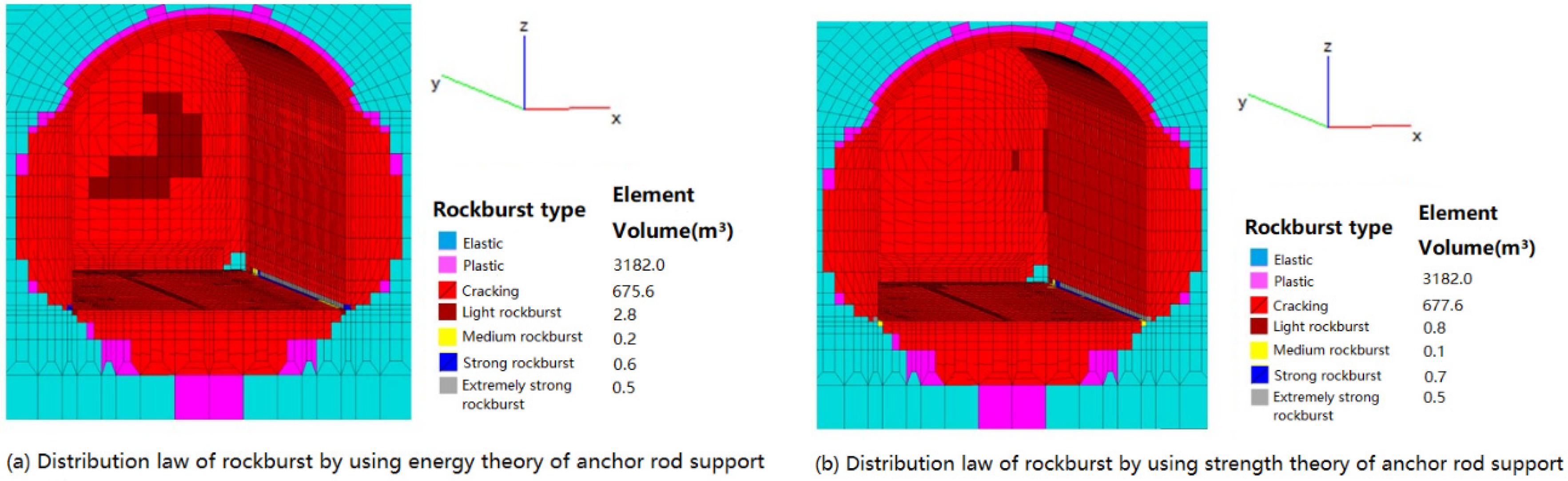
3. Numerical Analysis Method for Rockburst Control with Anchor Rod Reinforcement

According to the strength theory of rockburst, a rockburst may occur when the strength of the rock mass is damaged to the extent that it cannot resist the stress concentration after the excavation of the underground cavern. Therefore, using anchor rod support to increase the integrity of the surrounding rock improves its stiffness and reduces the strength damage and stress concentration, which is the most effective measure to prevent rockburst. Due to the need to compare the anchor bolt schemes during the design process, multiple models need to be established according to conventional methods and the difficulty in coordinating anchor rod elements with rock mass elements in numerical calculations; this paper proposes to use implicit anchor column elements to simulate the restraining effect of anchors on rockburst.

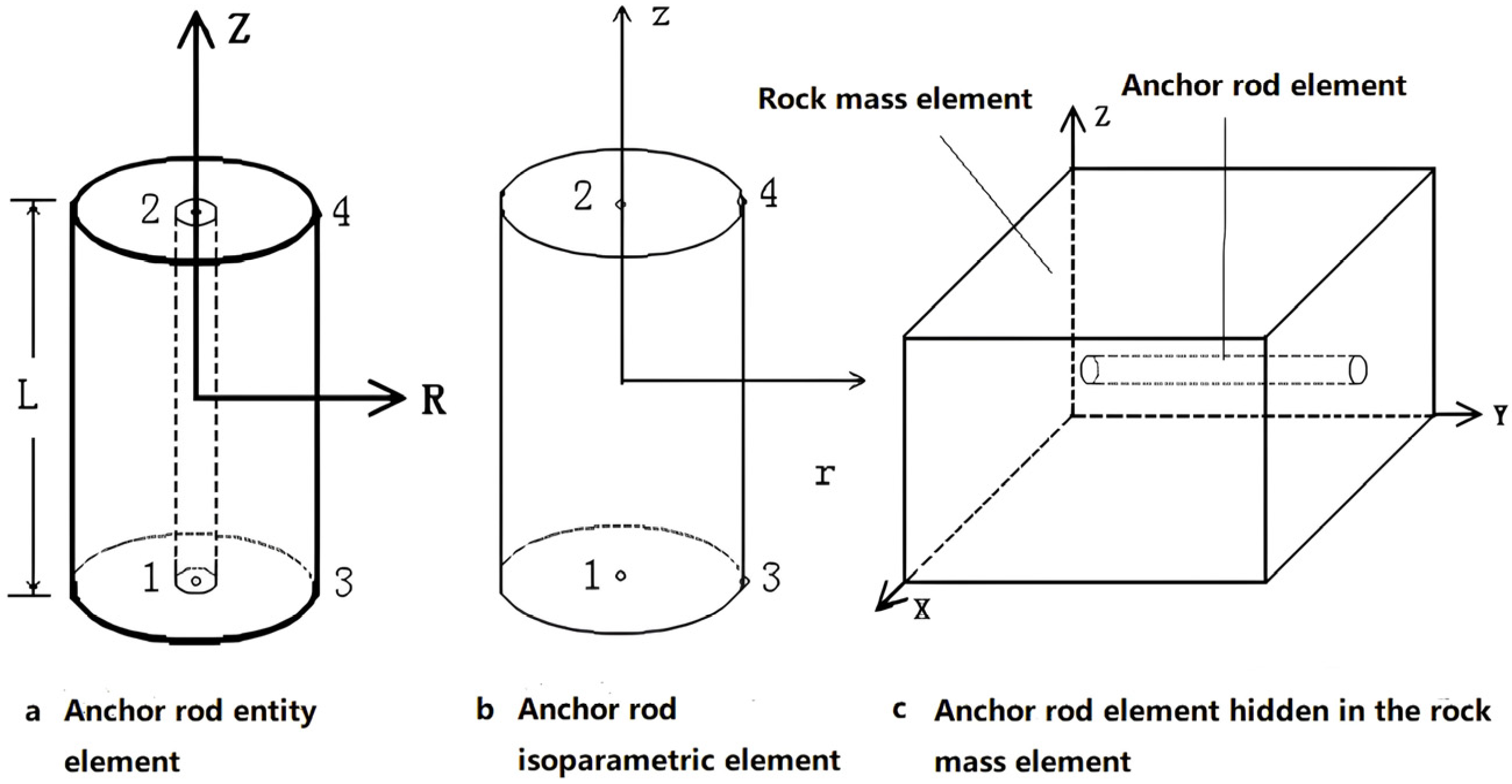
3.1. Mathematical Model of Implicit Anchor Rod Element

The role of anchor rod support can be summarized as consolidation combination and arch suspension [31]. When an anchor rod is inserted into the rock mass it will be combined with the surrounding rock mass, improving the bending and shear strength and increasing the internal resistance in the surrounding rock against rockburst. When the number of anchor rods increases to a certain extent, a bearing ring will be formed which can improve the integrity of the surrounding rock, effectively reducing the stress concentration, and increase the internal factors of rock mass resistance to rockburst. Assuming that there is no relative sliding between the anchor rod and the surrounding rock and that the support effect of the anchor is axisymmetric, the support effect of the anchor can be simulated by using an implicit cylindrical element. Such cylindrical elements can be simplified as an axisymmetric problem with anisotropic layer occurrence. Its stress–strain relationship can be expressed as follows:
σ r σ θ τ r θ = E r m 1 n μ r 2 1 + μ r μ θ 0 1 + μ r μ θ 1 μ r 2 n 0 0 0 b 2 n ε r ε θ ε r θ = D e ε
where m = 1 + μ r b , b = 1 μ r 2 n μ θ 2 , and n = E r / E θ , E r represent the radial elastic modulus, μ r represents radial Poisson’s ratio, E θ represents the axial elastic modulus, and μ θ represents Poisson’s axial ratio. The radial elastic modulus is taken based on the combination of anchor rods and rock masses. The axial elastic modulus is taken based on the shear stiffness of anchor rods and reinforced rock masses. Given that the anchor rod element is implicit in the three-dimensional rock mass element, we can establish the cylindrical isoparametric elements shown in Figure 1. According to the virtual work principle of the finite element, we can calculate the stiffness matrix of the anchor rod element by integrating the isoparametric elements as follows:
K g = B T D e B d c = 0 1 1 1 B T D e B 2 π r J d r d z
where B is the strain matrix of the column element and J is the value of the Jacobian matrix of the anchor column element. Based on the basic theory and the interpolation principle of finite element stiffness matrix calculation [32], the additional stiffness K R generated by the anchor rod in the rock mass element can be added to the stiffness matrix of the rock mass element according to the principle of stress–strain equivalence as follows:
K R = N T K g N
where [N] is the conversion matrix between the anchor rod element and the rock mass element and the specific calculation can be found in reference [32]. Superimposing the additional stiffness of Equation (7) into the rock mass element can reasonably and effectively reflect the effect of the anchor on rockburst containment.
Using implicit anchor rods, we can model the anchor rod elements and rock mass elements separately, which facilitates the analysis and calculation of various anchor rod arrangements, making modeling simple and effectively improving the calculation speed of anchor rod support. Using the equivalence principle of finite element interpolation to add the anchor rod element stiffness into the rock mass element stiffness can not only reflect the reinforcement and support effect of the anchor itself but also fully reflect the joint action of the anchor and the surrounding rock.

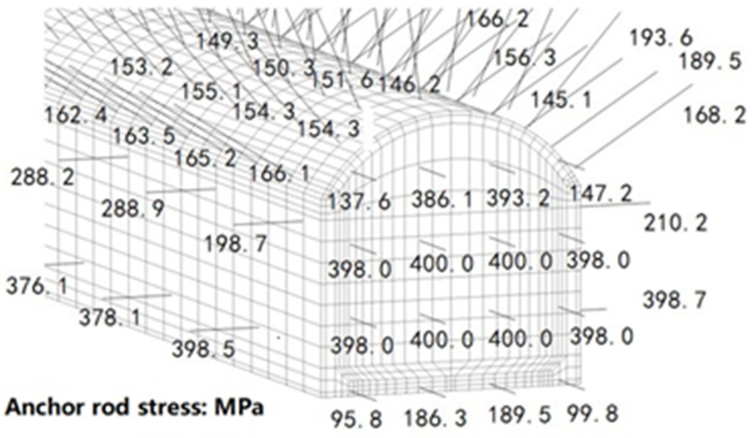
3.2. Analysis of the Rockburst Control Effect of Anchor Rod Support

According to the mechanism of anchor reinforcement of surrounding rock, anchor support mainly controls the rockburst in two ways. On the one hand, after the anchor rod is inserted into the rock mass, the strength of the rock mass is improved through consolidation combination and arch suspension to resist rockburst. On the other hand, the cracked rock mass and the complete rock mass are combined to form a complement through the system anchors which limits the deformation of the surrounding rock, reduces the stress concentration and energy accumulation, and curbs the occurrence of rockburst.
After the anchor rod is inserted into the rock mass element, it forms a cohesive bearing body with the surrounding rock, resulting in an increase in the stiffness of the combined element. Therefore, the elastic modulus E Y and compressive strength R Y of the combined rock mass can be increased based on the stiffness ratio between the rock mass element and the anchor rod element.
E Y = E s V s + n E g V g V s + n V g R Y = R s V s + n R g V g V s + n V g
where E s is the elastic modulus of the rock mass element, R s is the compressive strength of the rock mass element, V s is the volume of the rock mass element, E g is the elastic modulus of the anchor rod element, R g is the compressive strength of the anchor rod element, V g is the element volume of the anchor rod element, and n represents the number of anchor rods inserted into the rock mass element.
The elastic load part (Fe) of the total load F released during excavation will be quickly released. If the anchor rod support is provided promptly and the anchor rod passes through the cracked rock mass and connects with the stable rock mass to form a whole, the anchor rod and surrounding rock will jointly bear part of the plastic excavation release load Fp, as follows:
F p = α F = c ( 1 S ) F
where S is the elastic load release coefficient and α is the plastic load coefficient jointly borne by the anchor rod and surrounding rock. c is the coefficient of partial plastic load release during anchor rod construction which can be determined based on the anchor rod construction plan and surrounding rock conditions. After applying anchor rod support, the incremental variable plastic damage stiffness method is used to calculate Fp. Iterative methods for the determination of various coefficients can be found in reference [33].
K e Δ δ i j = Δ F p i + K D Δ δ i j 1
where K D is the stiffness matrix of the damaged element. After the iteration of each load, the damage stiffness is corrected. The rockburst grade is judged according to Equation (1) or Equation (3). The stiffness matrix of the rockburst element is reduced by the power exponential function according to the grade until it can be replaced by the air element.
During the iterative calculation process, for the anchor rod element that has not yielded, the additional load {f} generated by the anchor stress increment Δ σ in this iteration process of this level can be inversely superimposed on the rock mass and then substituted into Equation (10) for the next iteration, as follows:
f = A g Δ σ L , M , N , L , M , N T
where Ag is the area of the anchor rod and L, M, and N are the cosines of the anchor rod axis and the calculation coordinates. When the anchor rod stress exceeds the yield strength, the anchor rod no longer provides the support reaction. Due to the passive force on the anchor rod during the iteration process, the deformation stress continues to increase. In turn, the support reaction limits the deformation of the surrounding rock, effectively alleviating the concentration of stress, reducing the release of elastic energy, and preventing the occurrence of rockburst.

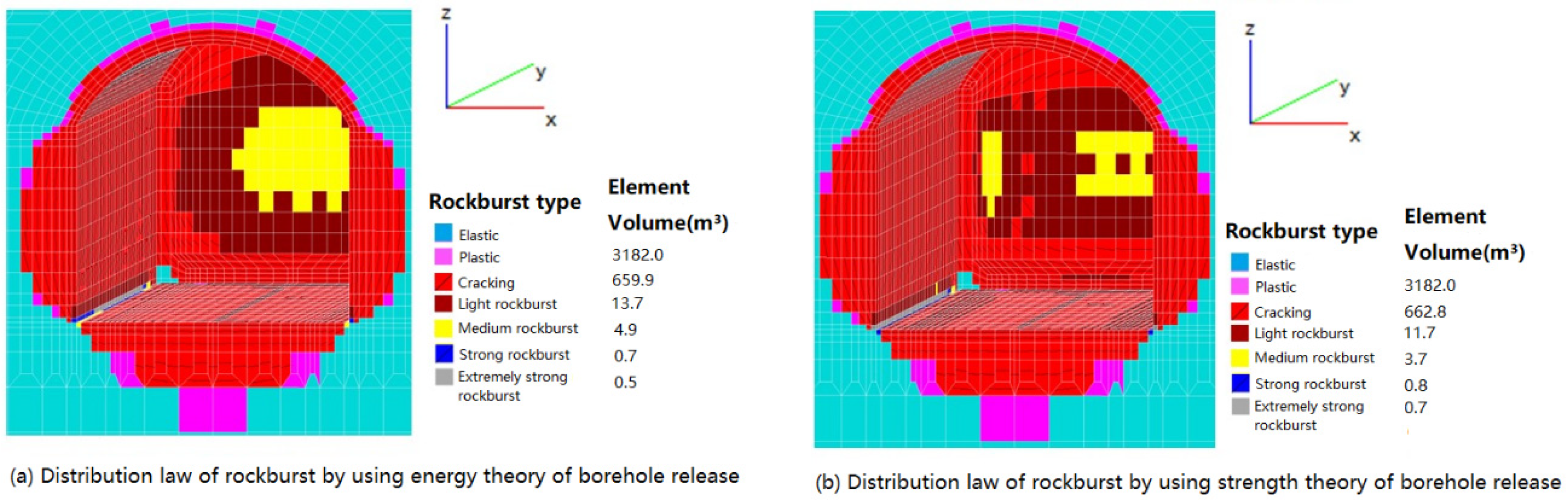
4. Numerical Analysis Method for Relieving Rockburst through Borehole Stress Release

According to the energy theory of rockburst, a rockburst may occur when the energy accumulated in the rock mass reaches a certain extent during the underground cavern excavation. For relatively light rockburst, drilling holes to release part of the energy from the tunnel face or injecting water to reduce the surface tension of the surrounding rock to reduce stress concentration is an effective measure to alleviate the occurrence of rockburst. Drilling holes on the tunnel face creates a cavity effect in the rock mass, releasing some of the rock mass energy and regulating the stress. To reasonably simulate the energy release and stress adjustment effects of drilling holes, we propose to use implicit hole elements to simulate the energy release effect of drilling.

4.1. Mathematical Model of the Implicit Hole Element

Stress relief holes with a diameter of 45 mm, a depth of 1–3 m, and a spacing of tens of centimeters can be drilled perpendicular to the tunnel face to release part of the energy, to alleviate the stress concentration. Due to the need to compare the borehole schemes during the design process, multiple models need to be established according to conventional methods. Owing to the small size of the boreholes, it is difficult to align them with the rock mass elements. Therefore, the hole elements can be independently modeled and embedded in the rock mass elements and the energy release effect of the borehole can be equivalently reflected through interpolation.
The mathematical model of the borehole element is similar to the anchor column element. But, considering the effect of the borehole, the rock mass within a distance of three times the diameter of the hole is treated as an anisotropic material to calculate its stiffness. Its radial elastic modulus is calculated according to the rock mass elastic modulus E and the axial elastic modulus is taken as (0.5~0.7) E based on the influence of the borehole diameter. Then, the stiffness loss of the borehole element is calculated according to Equation (6). The anchor rod element increases the stiffness of the surrounding rock while the borehole element weakens the stiffness, which is different from the anchor rod element. The existence of boreholes makes the anisotropy of rock mass along the axial direction more obvious so the rock mass element with boreholes must be calculated by forming a stiffness matrix according to the anisotropy. When arranging more than two stress relief boreholes within the same rock mass element, the anisotropy caused by the two boreholes needs to be vector superimposed. As shown in Figure 2, the vectors in the axial direction of the two boreholes A and B can be superimposed first to determine the normal vector A B in the layered direction of the rock mass element and then the stiffness matrix of the two boreholes A and B can be converted to the main plane A B according to the following formula:
K R i = R i T K z i R i
where K z i represents the element stiffness generated by the i-th borehole element along its axis direction, K R i represents the stiffness of the i-th borehole element superimposed to the stiffness in the rock mass element, R i is the three-dimensional coordinate transformation matrix between the axis direction of the i-th borehole element and the direction of the synthetic principal vector A B , and i represents the number of the borehole element in the rock mass element.
The borehole element is independently implicit in the rock mass element, similar to the stiffness of the anchor rod element. According to the interpolation principle of the finite element, the stiffness of the borehole element shall be superimposed into the rock mass element according to Equation (7) and then the influence of the borehole element shall be deducted from the stiffness matrix of the rock mass element. So, the combined stiffness of the rock mass element with boreholes K R Z is
K R Z = K E 1 i N T K R i N
where K E is the anisotropic rock mass element stiffness calculated according to the principal axis vector direction synthesized by the number of boreholes and N is the conversion matrix between the borehole and rock mass element calculated in reference [32].
The use of implicit borehole elements not only simplifies the analysis and calculation of different borehole arrangements but also accurately represents the reduction in stiffness of rock elements due to drilling holes and effectively demonstrates their role in mitigating rockburst.

4.2. Energy Release Calculation of the Borehole Element

The use of boreholes to control rockburst has two main functions: one is releasing part of the energy of the rock mass through drilling and the other is adjusting the stress of the surrounding rock mass by weakening the stiffness to slow down the stress concentration.
For part of the energy released by the borehole element, the energy release can be calculated using the following equation based on the stress intensity σ0 of the rock mass element that was drilled and the ratio of the borehole element volume to the rock mass element volume, as follows:
Δ W k = V k V R × 0.5 σ 0 2 E
where V k represents the volume of the borehole element, V R represents the volume of the rock mass element, and E is the elastic modulus of the rock mass element. The element stress intensity can be calculated according to the principal stress of the rock mass element where the borehole is located:
σ 0 = σ 1 σ 2 2 + σ 2 σ 3 2 + σ 3 σ 1 2 / 2
Drilling increases the energy dissipated in rock mass cracking and expansion during unloading. Therefore, when using Equation (3) to determine the rockburst, the released energy caused by drilling holes should be added to Ws. Then, the W s k consumed by the rock mass element for cracking and expansion after drilling holes is
W s k = W s + i = 1 n Δ W k i
where n represents n boreholes in the rock mass element.
We can first calculate the load release generated by boreholes according to the size of the borehole element and then calculate the relief effect on the rock mass stress concentration according to the load release. Considering the drilling as a plane deformation problem, according to the circular pipeline stress and displacement elastic theory, under the action of stress σ 0 , the radial displacement of the borehole radius R is [34]
u r = r 0 1 + μ E σ 0
where μ is the Poisson’s ratio of the rock mass. Considering the radial symmetry of the borehole element, the stiffness of the two-dimensional borehole element can be calculated according to Equation (6) which can be converted into three-dimensional stiffness according to two mutually perpendicular radial directions, as follows:
K Z 3 = S T K Z 2 S = k r r 0 k r z 0 k r r k r z k z r k z r k z z
where [S] is the conversion matrix between two-dimensional and three-dimensional stiffness determined based on the directional cosines of the two-dimensional and the converted three-dimensional coordinates. Assuming that the axial displacement of the borehole element is not taken into account and u z = 0 , the release load of the borehole element can be obtained as
f = K Z 3 u = k r r 0 k r z 0 k r r k r z k z r k z r k z z u r u r u z
According to the location of the borehole element in the rock mass element, using the finite element interpolation principle, the load {f} released from the borehole element can be converted into the node load {F} of the rock mass element using the following equation:
F = N T f
where [N] is the node interpolation shape function of the borehole element. The node loads of rock mass elements generated by the borehole element are all reversely applied to the structure and are substituted into the overall equilibrium Equation (10). Then, a balance calculation is performed and we can calculate the relief σsm of the stress concentration and the energy release ΔWe caused by stress and strain changes.
By substituting the maximum stress concentration value σsm of the rock mass element after drilling holes into Equation (1), the decrease in rockburst can be determined based on strength theory. By superimposing the energy release value ΔWe of the rock mass element increased by drilling holes into Ws, the decrease in rockburst can be judged based on the energy theory according to Formula (3).

5. Analysis of the Rockburst Control Effect in Deep Tunnel Excavation

In this paper, the engineering measures to contain rockburst in the Jiulongling Water Conveyance Tunnel Project in the Quanmutang Irrigation Area of Hunan Province are simulated and analyzed by using borehole stress relief and anchor rod support. The calculation program was developed on the basis of the three-dimensional elastoplastic damage finite element program developed by the Underground Engineering Research Group of Wuhan University using Fortran. The three-dimensional elastoplastic damage finite element calculation software (FeaGraphics Version 1.7) was fully validated in more than 100 large hydropower station underground caverns in China and worldwide. The specific calculation method is shown in reference [31]. The analysis results of Quanmutang guided the practice of relevant support measures. According to the lithology of the tunnel, we took the section of the Jiulongling tunnel with a buried depth of about 280–300 m and established a three-dimensional finite element model with a total of 200,480 elements, as shown in Figure 3. The lithology of the surrounding rock is limestone and the physical parameters of the rock mass are as shown in Table 1.
According to the tunnel topography and burial depth, the initial geostress inversion is carried out. We can obtain the following results: the horizontal direction of the first principal stress at the tunnel is consistent with the direction of the tunnel axis and its value is between σ1 = 19~23 MPa. The horizontal direction of the second principal stress is perpendicular to the direction of the tunnel axis and its value is between σ2 = 14~18 MPa. The vertical direction of the third principal stress is consistent with the lithostatic stress and its value is between σ3 = 10~13 MPa. The geostress belongs to the medium–high stress level. Based on the geological conditions and rock mass characteristics, it is preliminarily determined that medium rockburst may occur during tunnel construction. In this paper, we use the elastoplastic damage finite element to simulate the damage evolution process of the surrounding rock during tunnel construction and excavation. Strength theory and energy theory are used to analyze the effectiveness of borehole stress relief and anchor rod support in controlling rockburst during tunnel excavation. The details are described as follows.
We use the incremental variable plastic damage stiffness method to carry out the staged loading iterative calculation for the diversion tunnel excavation and the distribution of rockburst grades is calculated according to the energy theory and the strength theory (see Figure 4). We can see from the figure that the rockburst grades and distribution laws are basically the same and that both are medium rockburst of a large scale on the tunnel face, with a volume of 9.0 m3. Light rockburst occurs around medium rockburst on the tunnel face and at the entire bottom turning range of the tunnel, with volumes of 10.3 m3 and 8.4 m3. The strong and extremely strong rockburst calculated by both theories occur at the corners of the tunnel bottom with high-stress concentration but the volumes do not exceed 0.8 m3. We can see that when we use energy theory and strength theory to evaluate the occurrence and grade distribution of rockburst in construction and excavation, rockburst is concentrated in the parts with enormous elastic strain energy release and large stress concentration which indicates that the incremental variable plastic damage stiffness method can fully reflect the mechanism and characteristics of rockburst occurrence calculated by energy theory and strength theory.
To alleviate the stress concentration in the surrounding rock and actively control rockburst, a total of 28 stress relief holes with a diameter of 50 mm, a depth of 1 m, and a spacing of 1–2 m were drilled in four rows and seven columns on the tunnel face. The borehole arrangement is shown in Figure 5a. We simulate the effect of the stress relief hole by using the borehole element and evaluate the rockburst control measures after drilling based on the energy theory and strength theory. We can see from the distribution of the rockburst grade that the volume of light, medium, strong, and extremely strong rockburst calculated according to the energy theory is 13.7 m3, 4.9 m3, 0.7 m3, and 0.5 m3 (see Figure 6a), respectively. Compared with the situation without the boreholes (see Figure 4a), the distribution of rockburst grade is similar except that (1) the volume of medium rockburst on the tunnel face has decreased by 52.4%, (2) about 33% of medium rockburst has changed into light rockburst, (3) 19.4% of rock mass has avoided rockburst, and (4) the volume of strong rockburst at the bottom corner of the tunnel without the boreholes has not changed. According to the strength theory, the volumes of light, medium, strong, and extremely strong rockburst are 11.7 m3, 3.7 m3, 0.8 m3, and 0.7 m3, respectively (see Figure 6b). Compared with the situation without the boreholes (see Figure 4b), the volume of medium rockburst on the tunnel face has decreased by 58.9%, in which about 39.3% of medium rockburst has transformed into light rockburst, 19.6% of rock mass has avoided rockburst, and the volume of extremely strong rockburst remains unchanged throughout the entire bottom corner range of the tunnel without drilling. We can see that the effect of borehole stress relief calculated by energy theory and strength theory on rockburst control is consistent and that the distribution of rockburst grade is similar. The effect of boreholes on rockburst is not strong in both calculations, indicating that the effect of boreholes on controlling rockburst is only partial and that this active control measure is only effective for controlling light rockburst.
Applying anchor rods is an effective measure to passively improve the stiffness of surrounding rock and control rockburst. When the tunnel excavation was completed, four rows of anchors (Φ18 [email protected] × 1.5 m, L = 1.5 m) were applied promptly on the tunnel face. Two rows of anchors (Φ18 [email protected] × 5 m, L = 1.5 m) were applied on the side wall. Six rows of anchors (Φ22 [email protected] × 2.0 m, L = 3.0 m) were applied on the top arch and the arrangement of the anchor rods is shown in Figure 5b. After using anchor rod support, according to the energy theory, the volumes of light, medium, strong, and extremely strong rockburst are 2.8 m3, 0.2 m3, 0.6 m3, and 0.5 m3, respectively (see Figure 7a). Compared with the situation without the anchor rod support (see Figure 4a), the medium rockburst was fully controlled on the tunnel face, with only a local light rockburst on the face. The entire rockburst volume decreased by 80.0%. In the bottom corner range of the tunnel without anchor rod support, the strong and extremely strong rockburst volume remained unchanged, with a volume of 1.3 m3 accounting for 6.34% of the entire rockburst volume. According to the strength theory, the volumes of light, medium, strong, and extremely strong rockburst are 0.8 m3, 0.1 m3, 0.7 m3, and 0.5 m3, respectively (see Figure 7b). Compared with the situation without the anchor rod support (see Figure 4b), only a 0.4 m3 rock mass element on the tunnel face experienced a light rockburst while the rockburst in other parts was basically controlled. The entire rockburst volume decreased by 89.0%. In the entire corner range of the bottom of the tunnel without anchor rod support, the strong and extremely strong rockburst volume remained unchanged, with 1.3 m3 still accounting for 6.87% of the entire rockburst volume. From this, we can see that the effect of using anchor rod support to control the rockburst is relatively obvious. Whether analyzed based on energy theory or strength theory, the control of the rockburst is obvious. From this, we can see that the effect of using anchor rod support to control the rockburst is relatively obvious. Whether analyzed based on energy theory or strength theory, the control of the rockburst is obvious.
Comparing the results of the two measures, we can see that using the borehole element is a measure that actively releases part of the energy in the rock mass through the local cavity effect, which is limited and works only for some light rockburst control. The anchor rod is a method that can reinforce the rock mass, improve the overall stiffness, limit the deformation of the surrounding rock, and provide support reaction force for the surrounding rock during stress adjustment. Therefore, the stress on the anchor rod is generally high in the area where the rockburst occurs. From the distribution of the anchor rod stress around the tunnel in Figure 8, we can see that the anchor rod stress is relatively high at the tunnel face where the rockburst occurs relatively strongly and at the corner of the tunnel where the stress is concentrated. On the tunnel face with relatively high energy release, some anchor rods have reached a yield stress of 400 MPa and the surrounding anchor rods are also close to yielding. The anchor rod stresses near the corner of the bottom of the tunnel are relatively high, reaching 370–398 MPa, which is also close to yielding. The above results indicate that borehole elements can relatively well reflect the characteristics of local stress release and alleviate rockburst and anchor rod elements can be used to effectively simulate the containment principle of the overall resistance to the rockburst of the surrounding rock reinforced by anchor rods.

6. Conclusions

According to the principle of active and passive rockburst control measures, the iterative of the three-dimensional elastoplastic damage finite element variable damage stiffness method is used to effectively simulate the rockburst control effect of borehole stress relief and anchor rod reinforcement support. The use of energy theory and strength theory to assess the effectiveness of borehole stress relief and anchor rod reinforcement support fully illustrates the mechanism of active and passive control of rockburst. Through the simulation analysis of examples of underground tunnel excavation engineering, the following conclusions can be summarized:
(1) The proposed implicit borehole element can effectively simulate the active effect of borehole stress relief on rockburst control. This method embeds the borehole element within the rock mass element. This not only facilitates the arrangement of borehole elements but also makes finite element modeling more convenient. Additionally, it allows for a reasonable reflection of the effect of different drilling directions on stress release. According to the concept of equivalent node load transfer in borehole stress relief, it effectively describes the changes in the external environment caused by relieving stress in the borehole. It also reasonably reflects the reduction in energy accumulation and stress concentration in the rock mass due to drilling. However, it is important to note that drilling only releases a portion of the energy stored in the rock masses. Therefore, the control of rockburst is relatively limited, indicating that boreholes are only effective in mitigating mild rockburst incidents;
(2) The proposed implicit anchor rod element can effectively simulate the stiffness reinforcement effect of the anchor rod on the surrounding rock and the passive resistance effect to prevent rockburst. Since the anchor rod element is implicit in the rock mass element and both are modeled separately, the anchor rod element provides great convenience for adjusting the anchor rod arrangement and support scheme. The use of column elements to simulate the support effect of anchor rods can reflect the overall reinforcement effect on the surrounding rock. By combining anchor rod consolidation and hanging into an arch, the overall stiffness of the surrounding rock is improved, the internal resistance of the surrounding rock is increased, and the occurrence of rockburst is effectively reduced. This method accurately reflects the interaction between the anchor rod and the surrounding rock. The anchor rod connects the surrounding rock, forming a cohesive unit that helps to prevent the release of energy in the rock mass. The surrounding rock undergoes deformation and the resistance is applied in reverse to reduce stress concentration, prevent the sudden release of energy, and mitigate rockburst occurrences. Since the effect of anchor rod reinforcement on the surrounding rock is significant, anchor rod support can effectively control strong rockburst;
(3) The use of three-dimensional elastoplastic damage finite element simulation for borehole stress relief and anchor rod support can effectively control rockburst, both actively and passively. This method accurately reflects the mechanisms behind these control measures. Using strength theory and energy theory to analyze and evaluate the rockburst control situation of borehole stress relief, both types of theoretical analyses indicate that the active control measure of borehole stress relief only partially improves the external environment of rockburst. Furthermore, these analyses suggest that it can only effectively control some light-grade rockburst. As for anchor rod support, there are slight differences in the rockburst control effects between the two types of analyses. The effectiveness of anchor rod support is demonstrated, indicating that it is a passive control measure that alters the internal factors of rock mass resistance to rockburst. This, in turn, improves the overall stiffness of the rock mass and effectively mitigates medium or strong rockburst incidents.

Author Contributions

Conceptualization, S.Z.; methodology, S.Z.; software, S.Z.; validation, S.Z., M.X. and Y.L.; formal analysis, S.Z., Y.L. and X.D.; investigation, Y.L.; resources, X.D. and Y.C.; data curation, T.X.; writing—original draft preparation, C.K.; writing—review and editing, Y.L., T.X. and Y.C.; visualization, X.D.; supervision, M.X.; project administration, M.X.; funding acquisition, M.X. All authors have read and agreed to the published version of the manuscript.

Funding

This research was funded by the Quanmutang Reservoir Engineering Science and Technology Innovation Project (Grant No. W-2022-72).

Institutional Review Board Statement

Not applicable.

Informed Consent Statement

Not applicable.

Data Availability Statement

The data that support the findings of this study are available from the corresponding author upon reasonable request.

Acknowledgments

The authors also thank the anonymous reviewers who proposed critical and constructive comments for the improvement in this paper.

Conflicts of Interest

Author Shuangqiao Zhan, Xingwu Du, Yuncai Chen and Tian Xing were employed by the company Hunan Water Resources and Hydropower Survey, Design, Planning and Research Co., Ltd. The remaining authors declare that the research was conducted in the absence of any commercial or financial relationships that could be construed as a potential conflict of interest. The authors declare that this study received funding from Quanmutang Reservoir Engineering Science and Technology Innovation Project. The funder was not involved in the study design, collection, analysis, interpretation of data, the writing of this article or the decision to submit it for publication.

References

  1. Sakhno, I.; Sakhno, S.; Vovna, O. Assesing a risk of roof fall in the development mine workings in the process of longwall coal mining in terms of Ukrainian mines. Min. Miner. Depos. 2020, 14, 15. [Google Scholar] [CrossRef]
  2. Terzaghi, K. Introduction to tunnel geology. In Rock Tunnelling with Steel Supports; Commercial Shearing & Stamping Company: Youngstown, OH, USA, 1946; pp. 17–99. [Google Scholar]
  3. Obert, L.; Duvall, W.I. Rock Mechanics and the Design of Structures in Rock; Wiley: Hoboken, NJ, USA, 1967. [Google Scholar]
  4. Hedley, D.G.F. Rockburst Handbook for Ontario Hardrock Mines; Energy, Mines and Resources: Ottawa, ON, Canada, 1992. [Google Scholar]
  5. Kaiser, P.K.; McCreath, D.R.; Tannant, D.D. Canadian Rockburst Support Handbook; Geomechanics Research Center: Sudbury, ON, Canada, 1996. [Google Scholar]
  6. Wang, J.A.; Park, H.D. Comprehensive prediction of rockburst based on analysis of strain energy in rocks. Tunn. Undergr. Space Technol. 2001, 16, 49–57. [Google Scholar] [CrossRef]
  7. Zhou, J.; Li, X.B.; Mitri, H.S. A critical survey of empirical methods for evaluating rockburst potential. In Proceedings of the 15th IACMAG, Wuhan, China, 19–23 October 2017; pp. 18–22. [Google Scholar]
  8. Dietz, M.; Oremek, G.M.; Groneberg, D.A.; Bendels, M.H.K. What is a rock burst? Zentralblatt Arbeitsmedizin Arbeitsschutz Ergon. 2018, 68, 45–49. [Google Scholar] [CrossRef]
  9. Kaiser, P.K.; Diederichs, M.S.; Martin, C.D.; Sharp, J.; Steiner, W. Underground works in hard rock tunnelling and mining. In Proceedings of the ISRM International Symposium, Melbourne, Australia, 19–24 November 2000; p. ISRM-IS. [Google Scholar]
  10. Tang, B. Rockburst Control Using Destress Blasting. Ph.D. Thesis, McGill University, Montreal, QC, Canada, 2000. [Google Scholar]
  11. Fan, P.X.; Wang, M.Y.; Yue, S.L.; Shi, C.Y. Review on the Evolution Law, Mechanics and Prevention of Strain Rockburst. J. Wuhan Univ. Technol. 2013, 35, 96–101. [Google Scholar]
  12. Guo, L.; Li, X.B.; Yan, X.M. Research Progress and Development Trend of Rockburst. Min. Technol. 2006, 2006, 16–20. [Google Scholar] [CrossRef]
  13. Wang, J.M.; Wu, X.X.; Zeng, X.H.; Yan, P. Active Prevention of Rock Burst by Blasting Technology in Jinping Auxiliary Tunnel. J. Yangtze River Sci. Res. Inst. 2014, 31, 114–119. [Google Scholar] [CrossRef]
  14. Yan, P.; Chen, X.R.; Shan, Z.G.; Zhou, Y. Study of rock-burst prevention measures based on controlling the super shear stress. Rock Soil Mech. 2008, 29, 453–458. [Google Scholar] [CrossRef]
  15. Lu, W.B.; Chen, M.; Yan, P. Study on Vibration Characteristics of Surrounding Rock Induced by Tunnel Excavation under High In-situ Stress. Chin. J. Rock Mech. Eng. 2007, 26, 3329–3334. [Google Scholar]
  16. Xie, W.Q. Mechanism of Rockburst in Underground Works and Countermeasures. Mod. Tunn. Technol. 2008, 45, 8–13. [Google Scholar]
  17. Li, Z.L.; Tang, H.Y. Evaluation of Rockburst Proneness by Elastic Strain Energy Indices. Min. Res. Dev. 2005, 25, 16–19. [Google Scholar] [CrossRef]
  18. Zhang, X.J. Pattern and damage evolution of unloading rockburst for high-stress hard rock. Rock Soil Mech. 2012, 33, 3554–3560. [Google Scholar] [CrossRef]
  19. Feng, X.T.; Chen, B.R.; Ming, H.J. Evolution Law and Mechanism of Rockbursts in Deep Tunnels: Immediate Rockburst. Chin. J. Rock Mech. Eng. 2012, 31, 433–444. [Google Scholar]
  20. Wang, M.Y.; Fan, P.X.; Li, W.P. Mechanism of Splitting and Unloading Failure of Rock. Chin. J. Rock Mech. Eng. 2010, 29, 234–241. [Google Scholar]
  21. Yang, F.J.; Zhou, H.; Lu, J.J.; Zhang, C.Q. An Energy Criterion in Process of rockburst. Chin. J. Rock Mech. Eng. 2015, 34, 2706–2714. [Google Scholar] [CrossRef]
  22. Shemyakin, E.I.; Kurlenya, M.V.; Kulakov, G.I. Classification of Rock Bursts. J. Min. Sci. 1987, 22, 329–336. [Google Scholar] [CrossRef]
  23. Bai, Y.F. Study on Mechanism and Pillar Rockburst Based on Catastrophe Theory; Central South University: Changsha, China, 2009. [Google Scholar]
  24. Wang, Y.H.; Li, W.D.; Li, Q.G.; Xu, Y.; Tan, G.H. Method of Fuzzy Comprehensive Evaluations for Rockburst Prediction. Chin. J. Rock Mech. Eng. 1998, 17, 493–500. [Google Scholar]
  25. Lu, J.Y. Theory and Practice of Rock Burst Prediction. J. Min. Strat. Control Eng. 1998, 32, 26–29. [Google Scholar]
  26. GB50487-2008; Code for Engineering Geological Investigation of Water Resources and Hydropower. China Astronautics Publishing House: Beijing, China, 2008.
  27. Xie, H.P. Damage Mechanics of Rock and Concrete; China University of Mining and Technology Press: Beijing, China, 1990. [Google Scholar]
  28. Cook, N.G.W. The Failure of Rock. Int. J. Rock Mech. Min. Sci. 1965, 2, 389–403. [Google Scholar] [CrossRef]
  29. Kidybinski, A. Bursting Liability Indices of Coal. Int. J. Rock Mech. Min. Sci. 1981, 18, 295–304. [Google Scholar] [CrossRef]
  30. Tang, B.Q.; Cao, P. Establishing the energy index of rock burst from the perspective of the full stress-strain curve. Nonferrous Met. Sci. Eng. 1995, 9, 15–20. [Google Scholar]
  31. Lu, S.L.; Tang, L.; Yang, X.A. Anchor Rod Anchoring and Anchoring Technology; China Coal Industry Publishing House: Beijing, China, 1998. [Google Scholar]
  32. Xiao, M. Three-Dimensional Elastoplastic Finite Element Analysis of Implicit Anchor Rod Column Elements in Underground Caverns. Chin. J. Geotech. Eng. 1992, 14, 19–26. [Google Scholar]
  33. Xiao, M.; Ren, J.Q.; Zhao, B.X.; Chen, C.; Chen, S.J. Numerical Simulation Analysis Method of the Surrounding Rock and Support Bearing Capacity in Underground Cavern. Energies 2022, 15, 7788. [Google Scholar] [CrossRef]
  34. Xu, Z.L. A Concise Tutorial on Elasticity; China Higher Education Press: Beijing, China, 2018. [Google Scholar]
Figure 1. Mathematical Model of the Anchor Rod Element. (1–4 are the four node numbers of the anchor rod element).
Applsci 13 11197 g001
Figure 2. Determination of the normal direction of the rock mass element layer with boreholes. 1 is the starting point of borehole A, 2 is the endpoint of borehole A, 3 is the starting point of borehole B, and 4 is the endpoint of borehole B.
Applsci 13 11197 g002
Figure 3. Finite element calculation grid. 1 is Class II surrounding rock, and 2 is Class III surrounding rock.
Applsci 13 11197 g003
Figure 4. Distribution of rockburst during tunnel excavation.
Applsci 13 11197 g004
Figure 5. Boreholes and anchor rod arrangement on the tunnel face. 1 is Class II surrounding rock, 2 is Class III surrounding rock, 3 is spray layer, and 4 is concrete lining. Due to the current excavation stage, 3 and 4 are classified as Class II surrounding rocks like 1.
Applsci 13 11197 g005
Figure 6. Distribution of rockburst after borehole release.
Applsci 13 11197 g006
Figure 7. Distribution of rockburst after anchor rod support.
Applsci 13 11197 g007
Figure 8. Stress distribution of anchor rods.
Applsci 13 11197 g008
Table 1. The physical parameters of the rock mass.
Elastic Modulus EDeformation Modulus E0Bulk Density γ
15–20 GPa8~10 GPa2.65~2.7 kN/m3
compressive strength Rbfriction coefficient fcohesion C
60~70 MPa0.95~1.00.65~0.7 MPa
Poisson’s ratio μKz = 1.2Ky = 1.9
0.22~0.23Kx = 1.5Kxy = 0.132
Disclaimer/Publisher’s Note: The statements, opinions and data contained in all publications are solely those of the individual author(s) and contributor(s) and not of MDPI and/or the editor(s). MDPI and/or the editor(s) disclaim responsibility for any injury to people or property resulting from any ideas, methods, instructions or products referred to in the content.

