Article

Methodology for Selecting an Ideal Thermal Gasification Technique for Municipal Solid Waste Using Multi-Criteria Decision Analysis

by
Zakariya Kaneesamkandi
1,*,
Ateekh Ur Rehman
2,
Yusuf Siraj Usmani
2,
Abdul Sayeed
1 and
Hammed Sodiq Alabi
1
1
Department of Mechanical Engineering, King Saud University, Riyadh 11421, Saudi Arabia
2
Department of Industrial Engineering, King Saud University, Riyadh 11421, Saudi Arabia
*
Author to whom correspondence should be addressed.
Appl. Sci. 2023, 13(23), 12675; https://doi.org/10.3390/app132312675
Submission received: 12 November 2023 / Revised: 20 November 2023 / Accepted: 23 November 2023 / Published: 26 November 2023
(This article belongs to the Special Issue Advances in Biofuels and Bioenergy Production)

Abstract

:

Featured Application

Selecting the ideal strategy for thermal gasification of municipal solid waste from among different available gasification options using their important performance attributes is accomplished using multi-criteria decision analysis. This method will guide decision-makers like urban planners and energy engineers.

Abstract

Awareness of the consequences of waste mismanagement has resulted in urban planners looking for effective disposal techniques with the added benefit of energy generation. The decision regarding an energy conversion technique to adopt on a community level is based on different technology assessment factors with maximum weightage on environmental effects. Gasification techniques in general and thermal gasification strategies in particular are appropriate methods when environmental impacts are to be minimized. Thermal gasification techniques have evolved with different configurations, syngas generation rates, and other advantages and disadvantages; hence, the selection of the right technique is essential, and establishing guidelines for decision-makers is necessary. The six different gasifiers considered in the present study were updraft gasifiers, downdraft gasifiers, cross-draft gasifiers, bubbling fluidized bed gasifiers, circulating fluidized bed gasifiers, and dual-bed fluidized bed gasifiers. The assessments performed in the present study are based on the attributes of the different techniques using the multi-criteria decision method. Multi-criteria decision analysis is an appropriate method proven to be an ideal procedure in these situations. Attribute values for gasifier performance, environmental effects, economic performance indices, and fuel requirements were determined from collected waste assessment data and published information. Analysis was performed for both recycling and non-recycling scenarios of waste utilization by applying different weight scenarios for the attributes. Results of the study indicate that downdraft gasifiers showed the best performance in terms of environmental effects under the recycling scenario, with 0.1% and 0.0125% by volume of carbon dioxide and methane emissions, and under the non-recycling scenario, with 0.125% and 0.02% by volume of carbon dioxide and methane emissions. Downdraft gasifiers had high overall rankings in performance when evaluated against different entropy weights for both scenarios. The results of the study can be applied to urban communities in different climatic regions as well as for different scales of operation.

1. Introduction

Technologies for discarding municipal solid waste (MSW) and at the same time producing electricity from it are treated as important strategies by policymakers for overcoming environmental hazards, excessive energy costs resulting from conventional sources, and increasing demand. Presently, about 70% of the waste generated in urban regions all over the world is landfilled, about 19% is recycled, and about 11% is used to generate energy [1]. Conversion of waste to energy helps to simultaneously solve the requirement to discard waste as well as the need for energy [2].
Incineration by complete burning of waste is an effective method for reducing the volume of MSW and for producing energy for different purposes. Approximately 60% of the weight and 90% of the volume is reduced by this method [3]. One of the disadvantages of incineration is the gaseous emissions which include global warming-causing gases like carbon dioxide and methane and other harmful emissions like nitrous oxide, sulfur dioxide, and other nitrogen oxides [4]. Combustion of MSW using a fluidized bed has the potential to provide cooling and electricity under specific geographical and operating conditions [5]. Thermal gasification of MSW is a more complex process compared to incineration, wherein the waste is converted to simpler molecules, and hence the production of gases like dioxins and furans is prevented [6]. Thermal gasification is the process of converting solid fuels into combustible gaseous products by heating the fuel to temperatures of 750 to 1200 °C in an endothermic and controlled atmosphere, which is usually sub-stoichiometric. The process takes place in four phases, namely, drying, pyrolysis, combustion, and reduction. During the moisture removal process, the moisture in the fuel is evaporated. During the pyrolysis process, the volatiles, light hydrocarbons, and tar are separated from the fuel. During the combustion process, carbon and hydrogen in the fuel are changed to carbon dioxide, methane, and hydrogen. In the reduction phase, the carbon dioxide is reduced to carbon monoxide. The gas is called a syngas or producer gas, and it contains the following constituents: carbon monoxide, hydrogen, methane, carbon dioxide, and nitrogen [7].
Fixed-bed gasifiers are widely employed in commercial applications. In fixed-bed gasifiers, the feedstock is placed in a stationary bed. Fixed-bed gasifiers can be divided into three categories, updraft, downdraft, and cross-draft gasifiers, depending on which direction the feedstock and the gas flow. Apart from fixed-bed gasifiers, entrained flow gasifiers, fluidized bed gasifiers, circulating fluidized bed gasifiers, and dual fluidized bed gasifiers are other types of gasifiers applied to gasify MSW. The fluid used for gasification is air, oxygen, or steam, and each of these methods has its advantages and disadvantages.
In a fluidized bed gasifier (FBG), the feedstock is fluidized in a stream of air, oxygen, or hot gases. FBG involves the complete mixing of fuel and air, which reduces the cost and can be easily redesigned for higher capacities, easy operation, and higher fuel–air reaction rates, and these gasifiers are preferable to fixed-bed gasifiers due to their flexibility in handling a variety of feedstock compositions [8]. FBG operates below the melting point of ash, prevents agglomeration, and cannot handle char completely because of uninterrupted mixing of solids. FBG maintains an even bed temperature and operates between 800 and 1000 °C [9]. The different types of FBGs are circulating fluidized bed gasifiers, bubbling fluidized bed gasifiers, and dual-stage gasifiers with a conversion efficiency of 90–95% [10].
Entrained gasifiers have a high treatment capacity with a high temperature of at least 1250 °C and pressure of 20–80 bar compared to other types of gasifiers with the same bed volume; however, these gasifiers possess low thermal efficiency but high conversion efficiency [11]. Entrained bed gasifiers have superior mixing capabilities because air is mixed with the fuel before the actual gasification happens. These gasifiers are preferable to fixed-bed gasifiers due to their reduced emissions [12].
The present technologies for municipal solid waste management include landfills, incineration, composting, and gasification [13]. Since gasification has the promise of the least environmental effects and most cost benefits, decision-making on the right type of gasification process becomes crucial. The various technologies available for the gasification of MSW make decision-making regarding the method to be adopted challenging. Technology selection depends on multiple attributes like the economics of operation, emission occurrence, availability of trained manpower, and infrastructural facility in addition to the technical viability of the project. The present study analyzes the different gasification options available for MSW using the multi-criteria decision method (MCDM) tool. Initially, the different performance attributes of the different gasification technologies are identified. This is followed by the application of the MCDM tool under two different scenarios, namely, gasification without recycling the MSW and with recycling the MSW. The fixed-bed gasifiers analyzed in this paper include updraft gasifiers, downdraft gasifiers, and cross-draft gasifiers. The gasifiers analyzed under the fluidized bed category are the bubbling bed, circulating fluidized bed and dual-bed fluidized bed systems. This study involves the assessment data collected for Riyadh city, which is located in the arid climatic zone and is applicable to all urban regions around the world. The environmental data for carbon dioxide and methane emission and cost data are based on a global average from published data.

2. Methodology

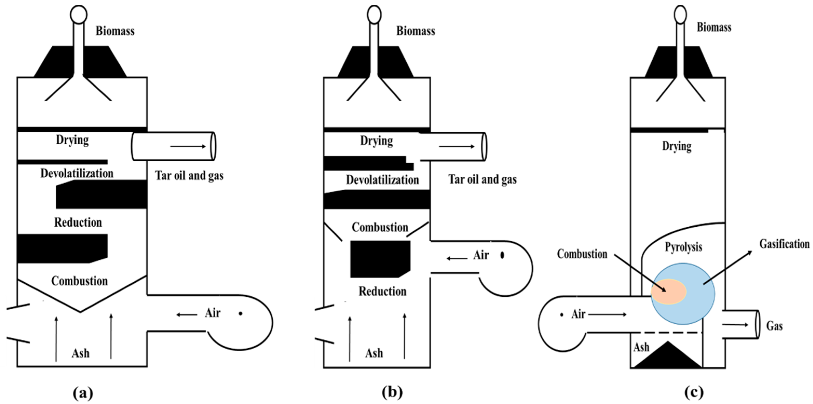
2.1. Fixed-Bed Gasifiers

Due to their simple construction and easy operability, fixed-bed gasifiers are widely employed in commercial applications. In fixed-bed gasifiers, the feedstock is placed in a stationary bed. Fixed-bed gasifiers can be divided into three categories, updraft, downdraft, and cross-draft gasifiers, depending on the flow direction of both the feedstock and the gas.

2.1.1. Updraft Gasifiers

In this configuration, the fuel is loaded in the upper part of the gasifier chamber, and air or oxygen is introduced from beneath, flowing upward through the fuel bed. Gasification reactions occur from top to bottom, passing through moisture removal, pyrolysis, combustion, and reduction stages as illustrated in the following Figure 1a. The fuel that flows through the gasifier from top to bottom contacts the hot gases moving up through the gasifier, and initially the drying process starts. This is followed by the pyrolysis process during which char formation takes place. The char that comes in contact with the combustion products is gasified producing carbon monoxide. These gasifiers are known for their thermal efficiency, easy operational procedures, and ability to accommodate feedstock with elevated moisture and ash contents. However, they produce the largest quantity of tar, have limited scalability, and require a longer start-up time [14]. An experiment was conducted to investigate a modified updraft fixed-bed gasifier and an adapted biomass feeding system aimed at diminishing the percentage of tar in the producer gas [15]. Although the resulting syngas had a caloric power slightly below the standard value for this reactor type, the maximum efficiency achieved in the gasification of woodchips was 77%. A separate experiment involving a modified updraft fixed-bed gasifier coupled with an adjusted biomass feeding mechanism was designed to decrease the tar levels in the producer gas [16]. This study revealed that the gasification efficiency was contingent on various factors, including the equivalence ratio, biomass characteristics, gasification agent, and gasifier setup.

2.1.2. Downdraft Gasifiers

In this configuration, the feedstock is loaded in the upper section of the gasifier, while the gasification agent is introduced in the lower portion. The operational mechanism of a downdraft gasifier follows a stepwise process involving drying, pyrolysis, oxidation, and reduction. Initially, solid biomass is introduced into the gasifier, initiating the drying phase when heat is applied to reduce the moisture content. Subsequently, during the pyrolysis stage, the partially dried biomass undergoes thermal decomposition without oxygen, yielding volatile gases, tar, and char. As the mixture descends, it enters the oxidation zone, where a carefully controlled amount of oxygen is introduced. In this area, the volatile gases generated during pyrolysis undergo combustion, releasing additional heat and forming combustion products. Finally, the mixture enters the lower reduction zone, characterized by a bed of hot carbonized material from the initial combustion. Here, any remaining oxygen reacts with the volatile gases, leading to the production of syngas that is both clean and energy-rich, primarily composed of carbon monoxide, hydrogen, and methane. Both the fuel and gas move downwards during the gasification process. Gasification reactions predominantly take place in the lower region of the gasifier, and the resultant gas is discharged from the upper section, and gasification reactions occur from top to bottom, passing through drying, pyrolysis, combustion, and reduction stages as shown in Figure 1b. The downdraft gasifier exhibits a quicker start-up time, low quantity of tar, and easy operation. However, it struggles with high moisture and feedstock and ash content, cannot operate effectively with certain unprocessed fuels, produces a lower heating value product gas when compared to updraft systems, and has limited scalability [17]. A study on the experimental analysis of a combined downdraft gasifier and multi-integrated gasification combustion system for MSW in remote areas provided information on the gasification efficiency, carbon conversion efficiency, specific gasification rate, quality of syngas, and combustible gas mixtures obtained by gasification in slow-moving updraft gasifiers [18]. Cooking with the gas produced using downdraft gasifiers was studied experimentally in the laboratory to study the gasification process, fuel effect, and its efficiency [19].

2.1.3. Cross-Draft Gasifiers

In this configuration, the biomass feed is fed into the top part of the gasifier, and the air is introduced in the orthogonal direction. The biomass descends, undergoing drying and eventual gasification, while the resulting product gas emerges from the system’s opposite side. The function of a cross-draft gasifier is based on the concept of biomass gasification using a unique cross-current flow arrangement. Solid biomass is horizontally fed into the gasifier. In the initial phase, the biomass undergoes a drying process when heat is utilized to reduce the moisture level. Following this, during the pyrolysis stage, the partially dried biomass undergoes thermal breakdown in the absence of oxygen, generating volatile gases, tar, and char. These gases traverse horizontally across the gasifier and then encounter an airstream for oxidation in the combustion zone. The carefully regulated introduction of air encourages the combustion of volatile gases, leading to the release of additional heat. The resulting mixture proceeds to the reduction zone, where any remaining oxygen reacts with the gases in the presence of a hot carbon bed, ultimately yielding syngas enriched in carbon monoxide, hydrogen, and methane. It exhibits minimal tar generation, offers a relatively quick engine start-up, and can process high-moisture biomass provided that the upper section of the gasifier remains open for venting; however, it is unsuitable for small-scale installations and may face challenges with a high ash content [13]. A model cross-draft, long-stick wood gasifier with a fixed bed was designed and tested to determine the gasification performance of the gasifier as shown in the above Figure 1c [20]. An experiment examining the gasification of wood-based biomass in a cross-draft setup revealed that the gasification efficiency is influenced by various parameters, including the equivalence ratio, biomass characteristics, the type of gasification agent used, and the configuration of the gasifier [21].

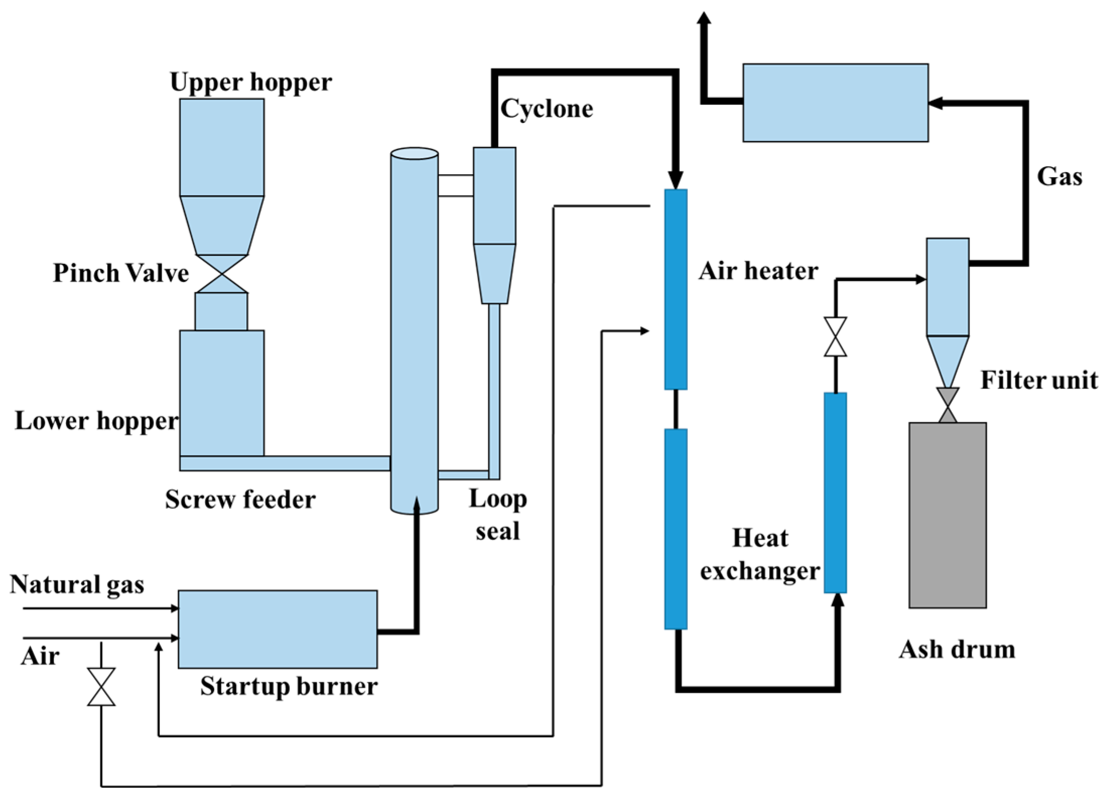
2.1.4. Circulating Fluidized Bed Gasifiers

The following Figure 2 shows the circulating fluidized bed gasifier. In circulating fluidized bed gasifiers, the material used in the bed, along with the product gases, is transported out of the reactor and cycled back to the bottom of the reactor using an air-driven system after passing through a ceramic fiber unit for gas cleaning. The gasifier comprises a riser that operates in a turbulent regime in order to facilitate moisture evaporation, pyrolysis, and gasification. It consists of a cyclone separator to capture the coarse particles of the bed to recycle the coarse particles of the bed material. This type of fluidizer can convert a high quantity of waste into energy. The operational principle of a circulating fluidized bed (CFB) gasifier involves the suspension of feedstock particles in an oxygen-rich gas, creating a fluidized bed within the gasifier. This fluidized bed, functioning like a fluid, facilitates efficient heat and mass transfer, thereby expediting the gasification process [22]. The CFB gasifier is characterized by fast fluidization, which optimizes heat and mass transfer for accelerated gasification. Additionally, it incorporates the circulation of char, extending the residence time of char to meet the requirements of reduction reactions and reduce char loss. The system is specifically designed to operate at high particle flux and high superficial gas velocity, preventing the formation of a distinct interface between the dilute region and the dense bed inside the riser. This operational condition is selected to ensure effective contact during the gasification process.

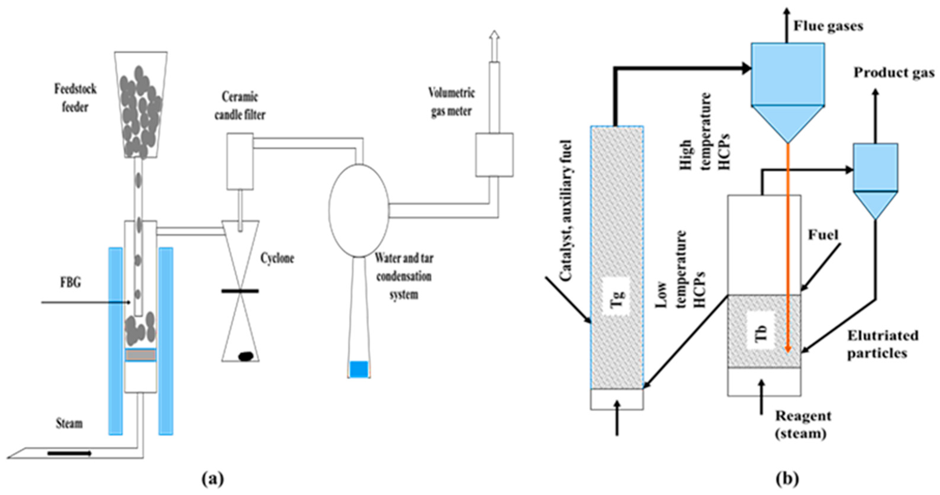
2.1.5. Bubbling Fluidized Bed Gasifiers

A bubbling fluidized bed (BFG) gasifier is shown in the following Figure 3a; the reactor consists of a vessel at the bottom through which the air for gasification is introduced into the system [23]. This system employs a fluidized bed composed of feedstock particles suspended in an oxygen-rich gas. This gasifier utilizes back-mixing to effectively blend incoming feedstock particles with those already undergoing gasification. Typically, small-sized coal particles (<6 mm) are employed to maintain fluidization or suspension of coal particles within the gasifier. The thorough mixing inside the gasifier results in a consistent temperature maintained throughout the reactor bed.
The fuel is continuously introduced from the top of the gasifier. The bed temperature of the gasifier is around 700–900 °C and is controlled by the fuel–air ratio. The BFG contains fine-grained materials of higher specific heat such as silica or alumina to operate at high temperatures. The product content of the gas with tar through pyrolysis in a BFG is <1 to 3 g/Nm3, which lies between those of the updraft and downdraft gasifiers [20]. The conversion efficiency of a BFG is 98.5 [24].

2.1.6. Dual Fluidized Bed Gasifiers

The multi-stage or dual fluidized gasifiers work on the principle of two fluidized bed gasification systems as shown in the above Figure 3b. This technology was developed to incorporate gas upgrading through the system and to avoid fuel loss [25]. The fluidized bed is divided into two zones for endothermic and exothermic processes for drying, pyrolysis, gasification, and combustion. The combination of a BFG and a fluidized bed combustor (FBC) makes the system more flexible for a variety of feedstocks and operating temperatures overwhelming the tar formation [24]. This type of gasifier has the advantage of producing H2-rich product gas and offering a synthetic process for capturing CO2 [26].

3. Performance Attributes and Scenarios

3.1. Performance Attributes

The performance attributes can be classified into different main classifications, namely, technology performance, economic performance, environmental performance, and fuel requirements. Technology performance indicators include the specific gas production rate (GPR), the carbon conversion efficiency (CCE), the energy content of the syngas produced (EC), the cold gas efficiency (CGE), and the tar generation rate (TG). The specific gas production rate is calculated by the ratio of the syngas flow rate ( Q S Y N ) to the fuel feeding rate ( Q B M ) into the gasifier as given by Equation (1).
G P R = Q S Y N Q B M N m 3 k g
The gasification performance of updraft gasifiers was experimentally tested with palm starch waste and was found to produce about 2.5 Nm3 of gas per kilogram of waste [26]. The carbon conversion efficiency (CCE) of the gasifier is the carbon leaving the gasifier in the form of syngas divided by the carbon available in the biomass fed into the gasifier. x j , c is the part of the carbon in the different components of the product gas 1 to j. y c is the part of the carbon in the biomass supplied to the gasifier as given by Equation (2).
C C E = Q S Y N × j = 1 n x j , c Q B M × y c
The energy content of the syngas is calculated from the combustible elements in the different components of the syngas measured using the gas calorimeter in KJ/Nm3.
The term cold gas efficiency (CGE) is the chemical energy leaving the gasifier associated with the cold and tar-free syngas divided by the chemical energy entering the fuel or MSW supplied to the gasifier.
Tar generation (TG) is one of the problems associated with gasifiers and has undesirable consequences when the syngas condenses downstream and results in clogging and blockages of burner holes when the syngas is burned directly or used in internal combustion engines.
The economic performance is assessed using two parameters, which are the life cycle cost (LCC) and the payback period. The LCC is determined by the sum of the initial cost (IC), the operating cost (OC), and the maintenance cost (MC), which are the recurring costs brought down to present value calculated over a period (n) of 15 years with an interest rate of r. The salvage cost (SC) at the current rate is deducted finally to calculate the LCC as given by Equation (3).
L C C = I C + n = 1 15 M C + O C 1 + r n S C  
The payback (PB) period represents the number of years needed to recoup the total cost invested in the project, and it is calculated by dividing the initial cash (IC) outlay by the annual or monthly cash inflow during the project as given by Equation (4).
P B y e a r s = I C I N F L O W U S D U S D y e a r
The environmental performance attributes include the water, air, and soil pollution caused by the MSW gasification process. The air-polluting emissions such as greenhouse gases like CO2 and CH4, furans, dioxins, and particulate matter are considered in this analysis. Soil and water pollution happens due to the storage of MSW on open lands, and it causes an enhancement in the organic matter content of the soil as well as an increase in certain heavy metals like copper, zinc, cadmium, nickel, and chromium [27].
Fuel requirements are the cost incurred due to fuel preparation activities to feed the fuel into the gasifier like the fuel size and moisture content specifications, which require fuel grinding or drying. The fuel ash content is another important criterion to be considered because catalytic activity is influenced by the fuel ash content.

3.2. Scenarios

Two different scenarios in the waste collection data are applied in this study. The first is the case of waste collection consisting of all the recyclable materials being removed and only the organic part of the MSW being available for gasification. The second case is the waste in which the organics as well as other combustible materials like wood, paper and board, plastic, and rubber wastes are used for gasification. The following Table 1 presents the calorific values of the inherent components of the waste collected in the central region of Saudi Arabia along with the specific items in the components. The waste was segregated to determine the different components of the waste. The total energy content in the non-recycled waste is 3.31 kWh/kg and that of waste after recycling is 1.297 kWh/kg.

3.3. Attribute Values

The attribute values calculated or collected from published data which were used for the MCDM analysis (refer to Table 2) were the same for the non-recycling scenario (refer to Table 3). The GPR values of the gasifiers are between 0.75 Nm3/kg and 3.6 Nm3/kg of feedstock. Dual fluidized beds have minimum performance due to the requirement to achieve a high syngas quality and low tar content and hence operate at lower temperatures and have a longer residence time for pyrolysis of the fuel [28]. Bubbling beds have a maximum gas output rate due to exposure of more surface area of the particles with the air with a maximum value of 3.6 Nm3/kg [29]. Downdraft and cross-draft gasifiers have an acceptable performance around 2 Nm3/kg [30]. Carbon conversion efficiency depends on the type of gasifier, feedstock characteristics, operating conditions such as temperature, pressure, airflow rate, and gasifier design [19,31]. Carbon conversion efficiency is determined from the carbon to oxygen ratio in the gasification process, and syngas with a higher level of hydrogen and less carbon monoxide is produced [32]. Updraft gasifiers have the highest tar content because the pyrolysis process takes place when the gases come in contact with the high-temperature fuel as it flows in the upward direction [33]. Cold gas efficiencies are inversely proportional to the gasification temperature, and since static beds have higher temperatures, their corresponding cold gas efficiencies are lower [34]. The installation cost of fluidized bed gasifiers is higher due to the air supply systems, gas cleaning systems, and fuel preparation systems used to meet the specifications of FB gasifiers. The higher product quality of the syngas and reduced nitrogen content make dual bed fluidization the best option in terms of the payback period [35]. Environmental performance includes emissions like carbon dioxide during the combustion reactions and passage across the bed without conversion to carbon monoxide. Methane emissions are possible during the storage of waste before gasification [36]. Normally, fixed-bed gasifiers have acceptability to higher sizes of feedstock compared with fluidized bed gasifiers. The same requirements are specified in terms of moisture content also [28,37].

3.4. MCDM Approach for Evaluating Thermal Gasification Techniques for MSW

Appropriate weights are determined in order to determine the criterion for ranking the different gasification techniques, which is the entropy weight method used by Shannon. This involves determination of the weight of the criterion and sub-criterion with reference to the thermal gasification technique for MSW. The MCDM is an approach one can apply when a set of alternative thermal gasification techniques are ranked according to a set of criteria. The MCDM used is direct and it makes the selection of the best alternative for each of the attributes by simple mathematical procedure by adopting suitable weights for comparison. The procedure involves the selection of the best gasification technique nearest to the best and farthest from the worst technique. For the A alternatives or options and C attributes or criteria and the grade of each thermal gasification technique concerning each criterion, refer to the above Table 2 and Table 3. The requirements to evaluate thermal gasification techniques for MSW using the above procedures are provided in the following sections.

3.4.1. Structure of the Decision Matrix and Its Standardization

If there are “I” thermal gasification techniques and “j” evaluation criteria for the thermal gasification technique, Cij is the jth criterion’s value in the ith thermal gasification technique. To remove the effect of the criterion dimension on proportionality, it is required to standardize the criteria using equations of relative optimum membership degree. For the benefit, (maximize) criterion, the attribute value of the jth criterion in the ith thermal gasification technique is standardized with the help of Equation (5), and in the case of the minimization criterion, the attribute value of the jth criterion in the ith thermal gasification technique is standardized by using Equation (6).
S i j = C ij min j C i j max j C i j min j C i j
S i j = max j C i j C i j max j C i j min j C i j
In Equations (5) and (6), Sij is the value of the standardized jth criterion of the ith alternative technique of gasification; Cij is the value of the jth criterion for the ith alternative method of thermal gasification. In the case of the evaluation set of the MCDM problem, if the jth criterion’s value in the ith method of gasification is Cij, then the decision matrix is D = [Cij]m × n, as given in Table 4 below.
The structure of the decision matrix is given in Equation (7) for standardization of all evaluation criteria for the thermal gasification methods considered in the analysis.
S i j = S 11 S 12 S 1 n : : : : : : : : S m 1 S m 2 S m n
After completion of the standardization for all given sets of thermal gasification techniques (refer to Equations (5) to (6)), the decision matrix is expressed for each set of thermal gasification technique types as shown below in Table 5 and Table 6 for the non-recyclable and recyclable MSW scenarios.

3.4.2. Estimation of Criterion Entropy Weights

The criterion followed for evaluation of the different gasification methods is represented by the entropy weight. A more important criterion is given more weight and vice versa. Equation (8) gives the entropy weight (Ei) calculation methodology used for the jth criterion of the ith alternative. Equation (9) gives the methodology to determine the criterion entropy weight (Wi).
E j = i = 1 m [ S i j l n ( S i j ) ] ln ( m )
W j = 1 E j [ 1 j = 1 n E j ]
Table 7 displays the entropy weight Ej for each of the thermal gasification method evaluation criteria.

3.4.3. Normalization of the Decision Matrix

Elimination of the effect of variation in criteria dimensions on the evaluation of the thermal gasification methods is necessary in order to normalize the matrix and in order to ensure equality among all the attributes in the same format. This requires the introduction of the normalized decision Rij obtained using Equation (10).
R i j = C i j C i j 2
After normalization of the different evaluation criteria for all given thermal gasification techniques (refer to Equation (10)), the decision matrix is expressed for each scenario type as shown below in Table 8 and Table 9.

4. Results and Discussion

4.1. Determine the Best and Worst Thermal Gasification Techniques for a Given Criterion

The normalized decision matrix multiplied by the associated entropy weight gives the best and the worst solution as in Equation (11).
V i j = W j R i j
The outcome of the above Equation (11) results in the set of best and worst solutions and is obtained using Equations (12) and (13), respectively.
V + = B e s t   s o u l t i o n = V 1 + , V j + , V n +
V j + = m a x i V i j   i f   j     m a x i m i z a t i o n   c r i t e r i a ;   m i n i V i j   i f   j     m i n i m i z a t i o n   c r i t e r i a
V = W o r s t   s o u l t i o n = V 1 , V j , V n
V j = m i n i V i j   i f   j     m i n i m i z a t i o n   c r i t e r i a ;   m a x i V i j   i f   j     m a x i m i z a t i o n   c r i t e r i a
The best and worst gasification strategies for the thermal gasification techniques are given in Table 10 below.
From Table 10, it is evident that in the case of a non-recycling scenario for criteria C3, C4, C5, and C7, the thermal gasification technique alternative 6: DUAL FB is the best strategy, and this technique is worst for criteria C1, C8, C9, C10, and C11. The gas produced by dual fluidized bed gasifiers has higher heating values and higher cold gas efficiency, as evident in the literature. Also, the tar content present in the gas is much lower [24]. This method is a poor performer in terms of emissions and fuel preparation requirements. In contrast, the thermal gasification technique alternative 4: BUBBLING BED is best for criterion C1, which is the gas production rate, and the alternative 5: CIRCULATING FB method is best for criterion C2, which is the carbon conversion efficiency. While the thermal gasification technique alternative 3: CROSS-DRAFT is the best strategy for criteria C6 and C8, it is the worst for criterion C3, and the alternative 2: DOWNDRAFT strategy is the best for criteria C10 and C12 but the worst for criterion C2. Similarly, one can make the observations regarding best and worst alternatives vs criteria to address the recycling scenario. As a decision-maker, it is very difficult to reach a unique preference under multiple criteria. Therefore, the closeness to an ideal solution for each alternative thermal gasification technique for a given criterion and the alternative thermal gasification technique ranking is essential. Here, in this study, five weighting scenarios are adopted (refer to Table 11 below), and the rankings are obtained.

4.2. Determine the Closeness to an Ideal Solution for Each Alternative Thermal Gasification Technique for a Given Criterion and Rank the Alternative

For a given alternative thermal gasification technique for a given criterion, its distance from the best ideal gasification strategy is obtained using Equation (14).
D i + = j ( V j + V i j )
For a given thermal gasification technique, its distance from the worst ideal thermal gasification technique is obtained using Equation (15).
D i = j ( V j V i j )
For a given thermal gasification technique, its closeness to the ideal thermal gasification technique is obtained using Equation (16).
C i = D i D i + + D i
In Equation (16) above, the Ci value ranges between one and unity. The alternative thermal gasification technique i with a maximum positive value of Ci ranked as number one. Thus, the decision matrix for the two MSW scenarios and the corresponding six thermal gasification techniques and 12 evaluation criteria is established according to the data in Table 6. The weighted decision matrix is estimated after the normalized decision matrix is established as given in Table 8, and the best and the worst solutions are obtained.
For the non-recycling MSW scenario, as shown in Table 11 above, the evaluation ranks for the six thermal gasification techniques are downdraft > circulating fluidized bed > bubbling fluidized bed > dual fluidized bed > updraft > cross-draft, when equal weights are assigned to each criterion. Since equally weighted criteria are an exaggeration, this is used as a reference. On the other hand, when the need is to focus on minimizing cost (Scenario 4), the preference order for the six thermal gasification techniques is circulating fluidized bed > dual fluidized bed>downdraft> bubbling fluidized bed > cross-draft > updraft. Similarly, when the objective is to minimize the environmental impact (Scenario 3) for the six thermal gasification techniques, the ranking is downdraft > cross-draft > updraft > circulating fluidized bed > bubbling fluidized bed > dual fluidized bed, and the downdraft strategy is the best option.
Similarly, for the recycling MSW scenario, as shown in Table 11 above, the evaluation ranks for the six thermal gasification techniques are downdraft > cross-draft > updraft > circulating fluidized bed > dual fluidized bed > bubbling fluidized bed when equal weights are assigned to each criterion. However, equally weighted criteria (Scenario 5) are an exaggeration, and this scenario is used as a reference. On the other hand, when the need is to focus on minimizing cost (Scenario 4), the preference order for the six thermal gasification techniques is circulating fluidized bed > bubbling fluidized bed > dual fluidized bed > downdraft > cross-draft > updraft. Similarly, when the objective is to minimize the environmental impact (Scenario 3) of the six thermal gasification techniques, the ranking is downdraft > cross-draft > updraft > circulating fluidized bed > dual fluidized bed > bubbling fluidized bed, in which case the downdraft gasifier is the best option.
A comparison of the different scenarios indicates that the downdraft gasifier ranks well. This paper mainly focuses on the selection of the best thermal gasification technique for meeting MSW requirements using the MCDM. The entropy weight and the MCDM, which have a high resolution and a simple calculation process, could objectively be used to evaluate the thermal gasification technique. This approach is different compared to other known approaches.

5. Conclusions

This paper presents a multi-criteria decision analysis approach to evaluate different thermal gasification techniques for municipal solid waste. The different options prioritized during the evaluation of the gasification technologies are based on the different attribute values collected for the specific gasification technologies from the preliminary research. For the non-recycling and recycling scenarios, the study ranks the thermal gasification techniques based on their technology performance indicators, economic performance indicators, environment performance indicators, fuel requirements, and attribute values. The selection of a specific gasification technology for an overall economic, energy, and environment purpose is a challenging task; thus, a sensitive decision-making strategy is required based on the available input factors to meet the different requirements of the gasifier. This study uses a decision matrix to standardize the criteria and sub-criteria related to the thermal gasification techniques for MSW. The entropy weight method by Shannon is used to determine the weight of the criteria and sub-criteria. This study adopts five weighting scenarios, and the closeness to an ideal solution for each alternative thermal gasification technique for a given criterion and the alternative thermal gasification technique rankings are determined. Though the entropy weight method adopted using the MCDM approach is straightforward for selecting the alternative thermal gasification method that is the closest to the ideal thermal gasification technique and farthest from the negative ideal thermal gasification technique, it is sensitive to the available internal and external conditions for the gasification technology. Downdraft gasifiers exhibit the best performance in terms of a higher weight of 60% for environmental effects under the recycling scenario, with 0.1% and 0.0125% by volume of carbon dioxide and methane emissions, and under the non-recycling scenario, with 0.125% and 0.02% by volume of carbon dioxide and methane emissions. Downdraft gasifiers have a maximum close value for the ideal solution, with maximum values of 0.710 and 0.706 for the non-recycling and recycling municipal solid waste for entropy based on the non-recycling data set and 0.727 and 0.703 relative to the entropy weight based on the recycling data set.
Circulating fluidized beds demonstrate the best ranking when a greater weight of 60% is chosen for the economic criterion. Dual-bed gasifiers rank well for non-recycling MSW, whereas updraft and dual-bed gasifiers rank equally for recycling MSW. The selection of the best gasification technique for MSW waste is sensitive to the environment and economic scenario based on the expert’s preferences. As per the expert 1 criteria, which give maximum weight to the environment, downdraft gasifiers emerge as the best suitable alternative considering the preference for the environmental impact. Decision-makers should carefully consider the weighting scenarios and the importance assigned to different criteria based on the environmental, economic, technological, and fuel requirement performance aspects.

Author Contributions

Experimental analysis: Z.K., A.U.R., and A.S.; Methodology: Z.K., A.U.R., Y.S.U., and A.S.; Theoretical model: Z.K., A.U.R., and A.S.; Writing and Original draft: Z.K. and A.S.; and Review and editing: A.S. and H.S.A. All authors have read and agreed to the published version of the manuscript.

Funding

This research was funded by the Deputyship for Research and Innovation, “Ministry of Education” in Saudi Arabia, grant number IFKSUDR_E155.

Institutional Review Board Statement

Not applicable.

Informed Consent Statement

Not applicable.

Data Availability Statement

The data presented in this study are available in this article.

Acknowledgments

The authors extend their appreciation to the Deputyship for Research and Innovation, “Ministry of Education” in Saudi Arabia for funding this research through the project number IFKSUDR_E155.

Conflicts of Interest

The authors declare no conflict of interest. The funders had no role in the design of the study; in the collection, analyses, or interpretation of the data; in the writing of the manuscript; or in the decision to publish the results.

References

  1. Osra, F.A.; Ozcan, H.K.; Alzahrani, J.S.; Alsoufi, M.S. Municipal solid waste characterization and landfill gas generation in kakia landfill, makkah. Sustainability 2021, 13, 1462. [Google Scholar] [CrossRef]
  2. Pan, S.-Y.; Du, M.A.; Huang, I.-T.; Liu, I.-H.; Chang, E.; Chiang, P.-C. Strategies on implementation of waste-to-energy (WTE) supply chain for circular economy system: A review. J. Clean. Prod. 2015, 108, 409–421. [Google Scholar] [CrossRef]
  3. Hasan, M.; Rasul, M.; Khan, M.; Ashwath, N.; Jahirul, M. Energy recovery from municipal solid waste using pyrolysis technology: A review on current status and developments. Renew. Sustain. Energy Rev. 2021, 145, 111073. [Google Scholar] [CrossRef]
  4. Tangri, N. Waste incinerators undermine clean energy goals. PLOS Clim. 2023, 2, e0000100. [Google Scholar] [CrossRef]
  5. Kaneesamkandi, Z.; Sayeed, A. Evaluation of Multi-Utility Models with Municipal Solid Waste Combustion as the Primary Source under Specific Geographical and Operating Conditions. Energies 2023, 16, 5696. [Google Scholar] [CrossRef]
  6. Chen, D.; Yin, L.; Wang, H.; He, P. Reprint of: Pyrolysis technologies for municipal solid waste: A review. Waste Manag. 2015, 37, 116–136. [Google Scholar] [CrossRef]
  7. Chen, W.-H.; Chen, C.-Y. Water gas shift reaction for hydrogen production and carbon dioxide capture: A review. Appl. Energy 2020, 258, 114078. [Google Scholar] [CrossRef]
  8. Arena, U. Fluidized bed gasification. In Fluidized Bed Technologies for Near-Zero Emission Combustion and Gasification; Elsevier: Amsterdam, The Netherlands, 2013; pp. 765–812. [Google Scholar]
  9. Bandara, J.C.; Jaiswal, R.; Nielsen, H.K.; Moldestad, B.M.; Eikeland, M.S. Air gasification of wood chips, wood pellets and grass pellets in a bubbling fluidized bed reactor. Energy 2021, 233, 121149. [Google Scholar] [CrossRef]
  10. Materazzi, M. Clean Energy from Waste: Fundamental Investigations on Ashes and Tar Behaviours in a Two Stage Fluid Bed-Plasma Process for Waste Gasification; Springer: Berlin/Heidelberg, Germany, 2016. [Google Scholar]
  11. Caballero, J.J.B.; Zaini, I.N.; Yang, W. Reforming processes for syngas production: A mini-review on the current status, challenges, and prospects for biomass conversion to fuels. Appl. Energy Combust. Sci. 2022, 10, 100064. [Google Scholar]
  12. Tremel, A.; Becherer, D.; Fendt, S.; Gaderer, M.; Spliethoff, H. Performance of entrained flow and fluidised bed biomass gasifiers on different scales. Energy Convers. Manag. 2013, 69, 95–106. [Google Scholar] [CrossRef]
  13. Nanda, S.; Berruti, F. Municipal solid waste management and landfilling technologies: A review. Environ. Chem. Lett. 2021, 19, 1433–1456. [Google Scholar] [CrossRef]
  14. Mishra, S.; Upadhyay, R.K. Review on biomass gasification: Gasifiers, gasifying mediums, and operational parameters. Mater. Sci. Energy Technol. 2021, 4, 329–340. [Google Scholar] [CrossRef]
  15. Pedroso, D.T.; Machín, E.B.; Silveira, J.L.; Nemoto, Y. Experimental study of bottom feed updraft gasifier. Renew. Energy 2013, 57, 311–316. [Google Scholar] [CrossRef]
  16. Sivakandhan, C.; Murali, G.; Prabhu, P.S. An experimental study of updraft biomass Gasifier using biofuels. Ecol. Environ. Conserv. 2018, 24, S115–S121. [Google Scholar]
  17. Anukam, A.; Mamphweli, S.; Reddy, P.; Meyer, E.; Okoh, O. Pre-processing of sugarcane bagasse for gasification in a downdraft biomass gasifier system: A comprehensive review. Renew. Sustain. Energy Rev. 2016, 66, 775–801. [Google Scholar] [CrossRef]
  18. Wiyono, A.; Gandidi, I.M.; Berman, E.T.; Pambudi, N.A. Design, development and testing of integrated downdraft gasifier and multi IGCS system of MSW for remote areas. Case Stud. Therm. Eng. 2020, 20, 100612. [Google Scholar] [CrossRef]
  19. Sutar, K.B.; Kohli, S.; Ravi, M. Design, development and testing of small downdraft gasifiers for domestic cookstoves. Energy 2017, 124, 447–460. [Google Scholar] [CrossRef]
  20. Saravanakumar, A.; Haridasan, T.; Reed, T.B. Flaming pyrolysis model of the fixed bed cross draft long-stick wood gasifier. Fuel Process. Technol. 2010, 91, 669–675. [Google Scholar] [CrossRef]
  21. Rozzi, E.; Minuto, F.D.; Lanzini, A.; Leone, P. Green synthetic fuels: Renewable routes for the conversion of non-fossil feedstocks into gaseous fuels and their end uses. Energies 2020, 13, 420. [Google Scholar] [CrossRef]
  22. Perpiñán, J.; Pena, B.; Bailera, M.; Eveloy, V.; Kannan, P.; Raj, A.; Lisbona, P.; Miguel Romeo, L. Integration of carbon capture technologies in blast furnace based steel making: A comprehensive and systematic review. Fuel 2023, 336, 127074. [Google Scholar] [CrossRef]
  23. Basu, P.; Fraser, S.A. Circulating Fluidized Bed Boilers; Springer: Berlin/Heidelberg, Germany, 1991. [Google Scholar]
  24. González-Vázquez, M.d.P.; García, R.; Gil, M.; Pevida, C.; Rubiera, F. Comparison of the gasification performance of multiple biomass types in a bubbling fluidized bed. Energy Convers. Manag. 2018, 176, 309–323. [Google Scholar] [CrossRef]
  25. Yan, J.; Salman, C.A. Waste Biorefineries: Advanced Design Concepts for Integrated Waste to Energy Processes; Elsevier: Amsterdam, The Netherlands, 2023. [Google Scholar]
  26. Fuchs, J.; Schmid, J.C.; Müller, S.; Hofbauer, H. Dual fluidized bed gasification of biomass with selective carbon dioxide removal and limestone as bed material: A review. Renew. Sustain. Energy Rev. 2019, 107, 212–231. [Google Scholar] [CrossRef]
  27. Saputro, H.; Muttaqin, I.; Supriyadi, S.; Fadlullah, V.; Fitriana, L.; Firdani, T.; Muslim, R.; Khaniffudin, K.; Lasmini, S.; Sutrisno, V.L. The performance of up-draft gasifier with various of air flow rate in gasification palm starch waste. In Proceedings of the MATEC Web of Conferences, Bandung, Indonesia, 18 April 2018; p. 08007. [Google Scholar]
  28. Mouhoun-Chouaki, S.; Derridj, A.; Tazdaït, D.; Salah-Tazdaït, R. A study of the impact of municipal solid waste on some soil physicochemical properties: The case of the landfill of Ain-El-Hammam Municipality, Algeria. Appl. Environ. Soil Sci. 2019, 2019, 3560456. [Google Scholar] [CrossRef]
  29. Hanchate, N.; Ramani, S.; Mathpati, C.; Dalvi, V.H. Biomass gasification using dual fluidized bed gasification systems: A review. J. Clean. Prod. 2021, 280, 123148. [Google Scholar] [CrossRef]
  30. Gunarathne, D. Optimization of the Performance of Down-Draft Biomass Gasifier Installed at National Engineering Research & Development (NERD) Centre of Sri Lanka. KTH. 2012. Available online: https://api.semanticscholar.org/CorpusID:198110070 (accessed on 12 October 2023).
  31. Meng, X.; De Jong, W.; Fu, N.; Verkooijen, A.H. Biomass gasification in a 100ákWth stea.m-oxygen blown circulating fluidized bed gasifier: Effects of operational conditions on product gas distribution and tar formation. Biomass Bioenergy 2011, 35, 2910–2924. [Google Scholar] [CrossRef]
  32. Hanchate, N.; Malhotra, R.; Mathpati, C.S. Design of experiments and analysis of dual fluidized bed gasifier for syngas production: Cold flow studies. Int. J. Hydrogen Energy 2021, 46, 4776–4787. [Google Scholar] [CrossRef]
  33. Basu, P. Biomass Gasification and Pyrolysis: Practical Design and Theory; Academic press: Cambridge, MA, USA, 2010. [Google Scholar]
  34. Furusawa, Y.; Taguchi, H.; Ismail, S.N.; Thangavel, S.; Matsuoka, K.; Fushimi, C. Estimation of cold gas efficiency and reactor size of low-temperature gasifier for advanced-integrated coal gasification combined cycle systems. Fuel Process. Technol. 2019, 193, 304–316. [Google Scholar] [CrossRef]
  35. Tanoh, T.S.; Oumeziane, A.A.; Lemonon, J.; Escudero-Sanz, F.J.; Salvador, S. A novel two-stage gasification strategy for nitrogen-free syngas production-pilot-scale experiments. Fuel Process. Technol. 2021, 217, 106821. [Google Scholar] [CrossRef]
  36. Yao, Z.; You, S.; Dai, Y.; Wang, C.-H. Particulate emission from the gasification and pyrolysis of biomass: Concentration, size distributions, respiratory deposition-based control measure evaluation. Environ. Pollut. 2018, 242, 1108–1118. [Google Scholar] [CrossRef]
  37. Morgalla, M.; Lin, L.; Seemann, M.; Strand, M. Characterization of particulate matter formed during wood pellet gasification in an indirect bubbling fluidized bed gasifier using aerosol measurement techniques. Fuel Process. Technol. 2015, 138, 578–587. [Google Scholar] [CrossRef]
Figure 1. (a) Updraft gasifier, (b) downdraft gasifier, and (c) cross-draft gasifier.
Applsci 13 12675 g001
Figure 2. Circulating fluidized bed gasifier.
Applsci 13 12675 g002
Figure 3. (a) Bubbling fluidized bed gasifier and (b) dual fluidized bed gasifier.
Applsci 13 12675 g003
Table 1. Heating values of the constituents of the waste.
Components LHV
kJ/kg
LHV
kWh/kg
%LHV
per Kg
Contents of the Components
Paper13,4843.7528.51.03Newspaper waste, boards, box board, carry bags, books, and tissues
Plastic35,0009.725.20.60Cutlery and cans, packings, water cans, and pipes and fittings
Glass00.004.60.00Bottles, containers, tube lights, and artifacts
Wood16,979.84.7280.38Toys and furniture
Textiles18,840.65.236.40.39Used dresses, diapers, etc.
Organics5582.41.55370.56Food waste and skins of fruits and vegetables
Others12,095.23.3610.30.35Bags, toys, tires, appliances, electronics, and automobile parts
Total Calorific Value (kWh/kg) 3.31
Total Calorific Value after Recycling (kWh/kg)1.297
Table 2. Attribute values used for the MCDM analysis for the non-recycling scenario.
Attributes/Non-Recycling ScenarioCriteriaObjective Units UpdraftDowndraftCross-DraftBubbling BedCirculating Fluidized Bed Dual Fluidized Bed
Technology performance indicatorsC1: GPRMaxNm3/kg2.52.831.8553.62.780.965
C2: CCEMax%0.7250.670.790.80.85030.811
C3: ECMaxMJ/Nm35.554.255.155.69516
C4: CGEMax%0.50.750.550.80.80.85
C5:T GMing/N·m3901.5080.50512.570.14
Economic performance indicatorsC6: LCCMinscale422444
C7: PBMinyrs645321
Environment performance indicatorsC8: CO2Min%0.1250.120.1150.157450.1350.22
C9: CH4Min%0.020.0250.0250.050.040.105
Fuel requirementsC10: Fuel SizeMaxmm52.56012.5690.4875
C11: Moisture contentMax%0.600.250.150.150.300.10
C12: Ash ContentMinScale0.250.060.750.250.250.25
Table 3. Attribute values used for the MCDM analysis for the recycling scenario.
Attributes/Non-Recycling ScenarioCriteriaObjective Units UpdraftDowndraftCross-DraftBubbling BedCirculating Fluidized Bed Dual Fluidized Bed
Technology performance indicatorsC1: GPRMaxNm3/kg2.202.631.662.902.500.78
C2: CCEMax%0.680.620.700.700.780.75
C3: ECMaxMJ/Nm34.004.153.504.104.559.50
C4: CGEMax%0.470.680.500.750.750.80
C5:T GMing/N·m3250.0018.0020.00161.90105.0020.00
Economic performance indicatorsC6: LCCMinscale5.004.004.005.005.005.00
C7: PBMinyrs6.004.005.003.002.001.00
Environment performance indicatorsC8: CO2Min%0.100.100.090.110.100.18
C9: CH4Min%0.0250.0350.0350.0600.0600.120
Fuel requirementsC10: Fuel SizeMaxmm25.5060.0012.506.009.000.49
C11: Moisture contentMax%0.6000.2500.1500.1450.3000.100
C12: Ash ContentMinScale0.250.060.080.250.250.25
Table 4. Matrix for decision making for the ith thermal gasification technique and jth criterion.
Evaluation Criterion (j)→
Alternative Thermal Gasification Techniques (i) ↓
12N
1C11C12C1n
2C21C22C2n
....
....
MCm1Cm2Cmn
Criterion Weight →W1W2Wn
Table 5. Standardization matrix S i j   for alternative thermal gasification techniques for the MSW non-recycling scenario.
Ai: Alternative Thermal Gasification Techniques
Evaluation Criterion (Cj) ↓UpdraftDowndraftCross-DraftBubbling BedCirculating Fluidized Bed Dual Fluidized Bed
C10.5830.7080.3381.0000.6890.000
C20.3050.0000.6660.7211.0000.782
C30.1060.0640.0000.0770.1231.000
C40.0000.7140.1430.8570.8571.000
C51.0000.0150.0040.1380.0760.000
C60.0001.0001.0000.0000.0000.000
C70.0000.4000.2000.6000.8001.000
C80.9050.9521.0000.5960.8100.000
C91.0000.9410.9410.6470.7650.000
C100.8741.0000.2020.0930.1430.000
C111.0000.3000.1000.0900.4000.000
C120.7251.0000.0000.7250.7250.725
Table 6. Standardization matrix S i j   for alternative thermal gasification techniques for the MSW recycling scenario.
Ai: Alternative Thermal Gasification Techniques
Evaluation Criterion (Cj) ↓UpdraftDowndraftCross-DraftBubbling BedCirculating Fluidized Bed Dual Fluidized Bed
C10.6710.8710.4141.0000.8120.000
C20.3440.0000.5000.5001.0000.813
C30.0830.1080.0000.1000.1751.000
C40.0000.6270.1040.8510.8511.000
C51.0000.0000.0090.6200.3750.009
C60.0001.0001.0000.0000.0000.000
C70.0000.4000.2000.6000.8001.000
C80.8610.8891.0000.7780.9440.000
C91.0000.8950.8950.6320.6320.000
C100.4201.0000.2020.0930.1430.000
C111.0000.3000.1000.0900.4000.000
C120.0001.0000.9210.0000.0000.000
Table 7. The entropy weight values for the different gasification methods.
Ej Entropy Weight
Evaluation Criterion (Cj) ↓Non-Recycling Scenario of MSWRecycling Scenario of MSW
C10.0650.077
C20.0710.062
C30.0810.074
C40.0850.083
C50.0970.086
C60.1250.123
C70.0660.065
C80.0940.099
C90.0950.084
C100.0780.064
C110.0660.065
C120.0780.119
Table 8. Normalized decision matrix R i j for thermal gasification techniques for the non-recycling scenario.
Alternative Thermal Gasification Techniques
Evaluation Criterion (Cj) ↓UpdraftDowndraftCross-DraftBubbling BedCirculating Fluidized Bed Dual Fluidized Bed
C10.3990.4510.2960.5740.4430.154
C20.3810.3520.4150.4210.4470.426
C30.2790.2540.2160.2610.2890.812
C40.2830.4250.3120.4530.4530.481
C50.9870.0170.0060.1370.0770.002
C60.4710.2360.2360.4710.4710.471
C70.6290.4190.5240.3140.2100.105
C80.3410.3270.3130.4290.3680.600
C90.1540.1930.1930.3860.3090.811
C100.6450.7370.1540.0740.1110.006
C110.7980.3320.1990.1930.3990.133
C120.2770.0660.8300.2770.2770.277
Table 9. Normalized decision matrix R i j for thermal gasification techniques for the recycling scenario.
Alternative Thermal Gasification Techniques
Evaluation Criterion (Cj) ↓UpdraftDowndraftCross-DraftBubbling BedCirculating Fluidized Bed Dual Fluidized Bed
C10.4030.4810.3040.5320.4590.142
C20.3900.3580.4050.4050.4510.434
C30.3040.3150.2660.3120.3460.722
C40.2840.4120.3050.4580.4580.488
C50.7870.0570.0630.5100.3310.063
C60.4350.3480.3480.4350.4350.435
C70.6290.4190.5240.3140.2100.105
C80.3580.3490.3140.3840.3310.628
C90.1590.2230.2230.3820.3820.764
C100.3790.8920.1860.0890.1340.007
C110.7980.3320.1990.1930.3990.133
C120.4910.1180.1470.4910.4910.491
Table 10. Best V+ and worst V solutions for thermal gasification techniques using corresponding Ej entropy weight values.
Ej Entropy Weight Non-Recycling ScenarioEj Entropy Weight Recycling Scenario
Evaluation Criterion (Cj) ↓V+Alternative #VAlternativeV+AlternativeVAlternative
C10.03840.01060.04140.0116
C20.03250.02520.02850.0222
C30.06660.01730.05360.0201
C40.04160.02410.04060.0241
C50.00060.09610.0053 and 60.0681
C60.02930.05910.0432 and 30.0531/5/6
C70.00760.04110.00760.0411
C80.02930.05660.03130.0626
C90.01510.07760.01310.0646
C100.05720.00060.05720.0006
C110.05210.00960.05220.0096
C120.00520.06530.01420.0581/4/5/6
# Note: 1: Updraft; 2: Downdraft; 3: Cross-draft; 4: Bubbling bed; 5: Circulating fluidized bed; and 6: Dual fluidized bed.
Table 11. Thermal gasification technique distance from the best ideal, the worst gasification method, and their ranks using various weighting scenarios.
Scenario 1: Entropy Weights Based on the Non-Recycling Data Set
Thermal Gasification Technique (i) ↓For Non-Recycling MSWFor Recycling MSW
Di+DiDi/(Di+ + Di)Rank CiDi+DiDi/(Di+ + Di)Rank Ci
Updraft0.11750.10460.471160.10150.08340.45124
Downdraft0.05970.14630.710210.05090.12230.70601
Cross-draft0.10390.11970.535540.08480.09810.53622
Bubbling bed0.09120.10940.545430.10070.06270.38356
Circulating fluidized bed0.08000.11890.597820.08520.07700.47463
Dual fluidized bed0.10760.12170.530750.11120.08840.44285
Scenario 2: Entropy Weights Based on the Recycling Data Set
Thermal Gasification Technique (i) ↓For Non-Recycling MSWFor Recycling MSW
Di+DiDi/(Di+ + Di)Rank CiDi+DiDi/(Di+ + Di)Rank Ci
Updraft0.10880.10930.501050.09810.07830.44404
Downdraft0.05650.15060.727210.04850.11500.70321
Cross-draft0.12040.10830.473560.07760.09510.55082
Bubbling bed0.08550.11380.571130.09640.06140.38916
Circulating fluidized bed0.07510.12080.616720.08290.07350.46973
Dual fluidized bed0.10200.12200.544640.10770.08040.42745
Scenario 3: 60% Weight to Environment Attribute, 20% to Performance Indicators and Rest Equal to 10% Each (Expert 1)
Thermal Gasification Technique (i) ↓For Non-Recycling MSWFor Recycling MSW
Di+DiDi/(Di+ + Di)Rank CiDi+DiDi/(Di+ + Di)Rank Ci
Updraft0.05550.21490.794730.05060.20060.79873
Downdraft0.03430.21040.859810.03530.18870.84231
Cross-draft0.05240.20850.799120.04700.19060.80212
Bubbling bed0.08790.14470.622250.08310.13850.62515
Circulating fluidized bed0.06090.17290.739640.07650.14880.66044
Dual fluidized bed0.21830.05690.206760.20870.04400.17416
Scenario 4: 60% Weight to Economic Attribute, 20% to Environment and Rest Equal to 10% Each (Expert 2)
Thermal Gasification Technique (i) ↓For Non-Recycling MSWFor Recycling MSW
Di+DiDi/(Di+ + Di)Rank CiDi+DiDi/(Di+ + Di)Rank Ci
Updraft0.17410.07930.312860.16180.07110.30516
Downdraft0.09640.12340.561530.09620.09830.50544
Cross-draft0.13210.10510.443050.13010.07730.37295
Bubbling bed0.10340.10830.511740.08120.10520.56443
Circulating fluidized bed0.08380.14040.626110.05670.13560.70511
Dual fluidized bed0.10640.16010.600820.08300.15820.65612
Scenario 5: Equal Weights to All
Thermal Gasification Technique (i) ↓For Non-Recycling MSWFor Recycling MSW
Di+DiDi/(Di+ + Di)Rank CiDi+DiDi/(Di+ + Di)Rank Ci
Updraft0.10910.10920.500350060.08700.46383
Downdraft0.06750.13860.672410.05910.11940.66891
Cross-draft0.11550.10360.472860.09620.08810.47802
Bubbling bed0.09640.10400.518930.10650.06340.37316
Circulating fluidized bed0.08270.11260.576420.08990.07680.46074
Dual fluidized bed0.11070.11650.512740.11750.08560.42145
Disclaimer/Publisher’s Note: The statements, opinions and data contained in all publications are solely those of the individual author(s) and contributor(s) and not of MDPI and/or the editor(s). MDPI and/or the editor(s) disclaim responsibility for any injury to people or property resulting from any ideas, methods, instructions or products referred to in the content.

