Article

Flexural Performance of Removable Deck Slabs with Fixing Device Details

1
Department of Architectural Engineering, Hanyang University, Seoul 04763, Republic of Korea
2
Division of Smart Architecture and Civil Engineering, Daejin University, Pocheon 11159, Republic of Korea
*
Author to whom correspondence should be addressed.
Appl. Sci. 2023, 13(8), 4903; https://doi.org/10.3390/app13084903
Submission received: 15 March 2023 / Revised: 4 April 2023 / Accepted: 12 April 2023 / Published: 13 April 2023
(This article belongs to the Special Issue Advances in Building Materials and Concrete)

Abstract

:
This study presents a new concept for a deck plate and an accompanying application for a slab system that is easy to fix and separate during construction, while ensuring safe construction loads and optimal flexural performance. Finite element analysis (FEA) was used to determine the load on the fixing device’s contact surface and the specimen’s shape. A direct tensile test was then performed using a universal testing machine to evaluate the anchorage performance of the fixing device. The results of this test were used to optimize the details of the fixing device, which were then evaluated for safety against construction loads. The installation interval and method of the fixing device were varied to determine the maximum installation interval, which was within 300 mm. Finally, flexural performance was evaluated based on the details and spacing of the fixing device installation. The results showed that the details and spacing of the fixing device did not have a significant effect on flexural performance, provided that safety against construction loads was secured. This study describes a promising solution for a slab system that is easy to install and separate during construction, while ensuring safety and flexural performance.

1. Introduction

The growing demand for high-rise buildings has resulted in the widespread use of steel and composite structures that combine steel and reinforced concrete. Such structures offer reduced cross sections, light member weight, and long spans, making them suitable for large buildings. As the size of buildings increases, the use of deck plates is also on the rise, as they help improve economic feasibility and shorten construction periods [1,2,3].
Unlike the conventional reinforced concrete (RC) structure, deck plates are manufactured by truss girder integration and serve as concrete formwork and load-bearing elements during construction, eliminating the need for temporary construction, such as supports [4,5,6]. However, despite their numerous benefits, several challenges remain to be addressed, such as the need to ensure the safety of the developed product during construction and use.
A conventional deck plate design consists of a truss girder with one upper reinforcing bar and two lower reinforcing bars connected by a lattice, with the truss girder and spacer contact welded to fix the position of the spacer. A spacer is used to separate the upper truss girder and the lower floor plate from each other, and a support member is used to support the truss girder. Deflection evaluation was performed according to the details of the truss girder to ensure safety during the construction of the conventional deck plate. The deflection of the deck plate varied depending on the lattice bar and deck height [7].
However, the fixing details of the lower floor and truss girder were not addressed, and this design presents a risk of corrosion due to the integration of the deck plate and truss girder, with the bottom plate made primarily of galvanized steel. Moreover, if there is a leak in the hardened concrete floor plate, it is difficult to locate and repair the damage or replace the deck plate. These issues prompted the development of alternative deck plate designs.
Several studies [8,9,10] have been conducted to address the issue of the inability to replace the lower plate of the truss girder integrated deck plate. A promising solution is a separable deck plate between the truss and the deck plate. This allows for the removal of the steel plate and plywood from the mold assembling the deck plate, eliminating the disadvantage of integrated deck plates. Research and development efforts are ongoing to optimize the performance of detachable deck plates and ensure their practical application in the construction industry.
Removable deck plates have attracted attention as a potential solution to the disadvantages of integrated truss girder deck plates. However, concerns have been raised regarding the concentrated stress at the junction between the bottom plate and the truss during construction load application, which may lead to collapse or deformation due to excessive deflection. Excessive coupling of the truss girder and the steel plate may also result in the deformation of the tensile reinforcing bar before concrete placement or weak coupling to the spacer or nut for demolding. As a result, research has focused on improving the structural safety of removable deck plates. Lee et al. [8] conducted a load test on a reusable deck to demonstrate structural safety during construction. However, their study did not consider the impact of the fixing device connecting the truss wire and the galvanized steel sheet on safety during construction, highlighting the need for further research on optimizing the fixing device.
A previous study [9] evaluated the safety of deck plates in which the lattice reinforcing bar and the steel deck were integrated during construction without the use of a fixing device. The experiment involved loading at four locations to simulate a uniformly distributed load. The results confirmed that the lattice reinforcing bar in the support section received a compressive force, resulting in buckling. However, the load in this study was only applied to the upper rebar. During actual construction, concrete is poured into the formwork installed on the lower floor to resist the load. It is necessary to consider this factor when applying the load to the deck plate system.
A recent study [10] described the development of a removable deck system in which a deck plate and fixing device were connected with bolts, and an experiment and numerical investigation were conducted to evaluate the safety of construction loading. The results indicated that the fixing device exhibited elastic behavior against the construction load. However, only the shape and load of the deck were considered main variables, and the study used two bolts to fix one lattice bar. Further research on the optimal installation plan, taking into account the shape, spacing, and installation method of the fixing device, is necessary to ensure the safety and reliability of the deck system during construction.
In this study, the procedure shown in Figure 1 was conducted to develop a new type of removable deck plate. First, the details of the fixing device were proposed, and the weak part of the fixing device was first analyzed by FEA to verify its safety. Based on the analysis results, anchorage tests were performed to find the optimal fixing device shape. Factors affecting deflection during construction were analyzed through the construction load test, and finally, the flexural performance was evaluated.

2. Research Significance

In this study, a slab system applying a new deck plate concept that is easy to fix and separate was developed. Details of an optimized fixing device that can be separated during construction were presented. The developed detail has the advantage of facilitating concrete floor repair as it is easy to demold the deck plate. In addition, it is easy to separate and assemble the lower plate of the deck plate and the truss girder; therefore, it can be easily assembled on-site in accordance with various construction situations compared with the existing deck plate. Through the results of this study, it is intended to secure the structural safety of the deck plate system developed during construction and use.

3. Fixing Device of a Removable Deck Plate

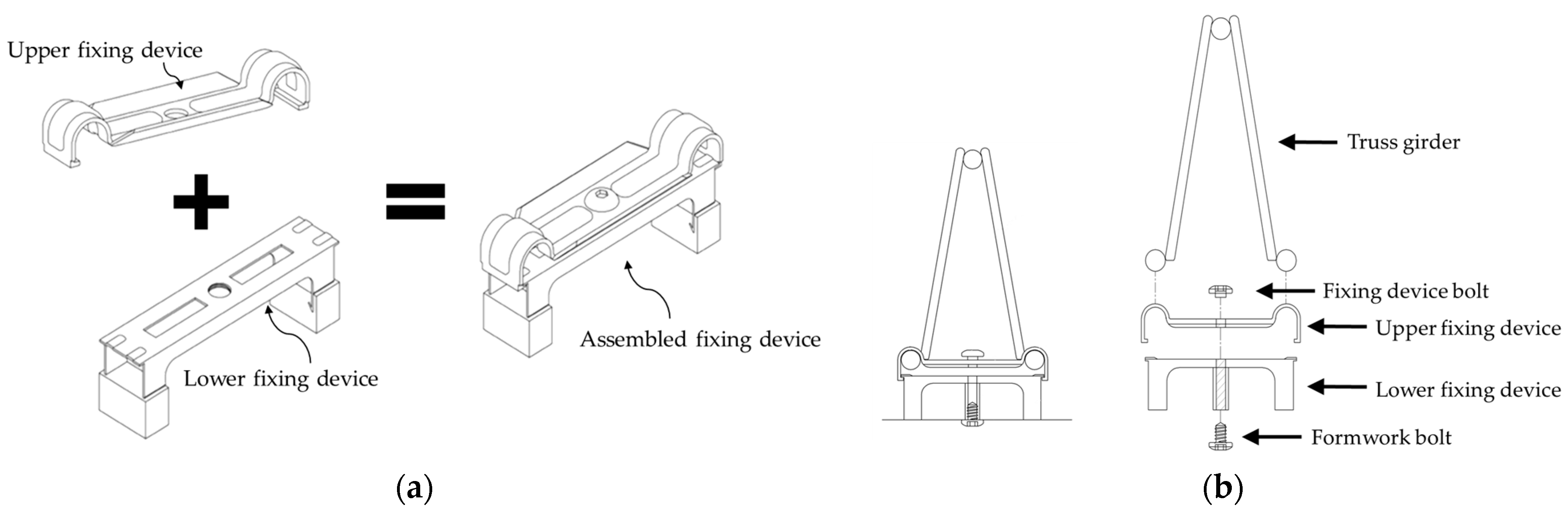
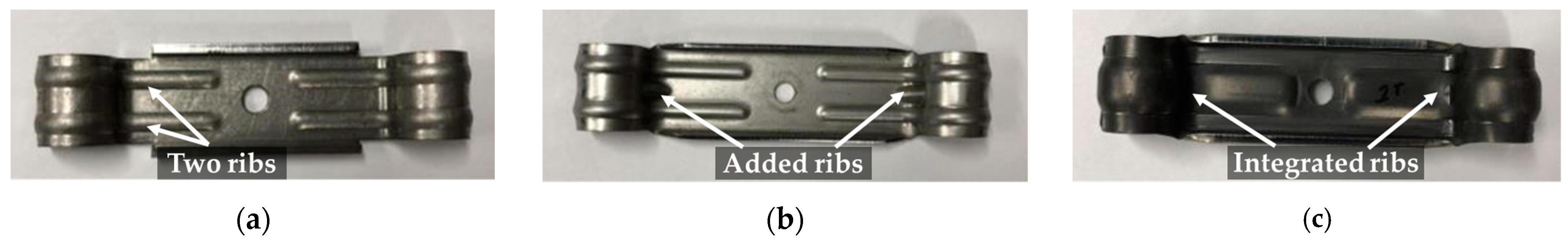
3.1. Details of Fixing Device

The composition of a removable deck plate is illustrated in Figure 2. This study proposes a removable deck plate that differs from existing ones in that it has a structure connecting spacers, truss girders, and the lower plate without welding points. The tension reinforcing bar at the lower part of the truss girder is fixed by bolts for the fixing hardware and the formwork. In addition, the lower part of the fixing hardware acts as a spacer and securely fixes the truss girder.

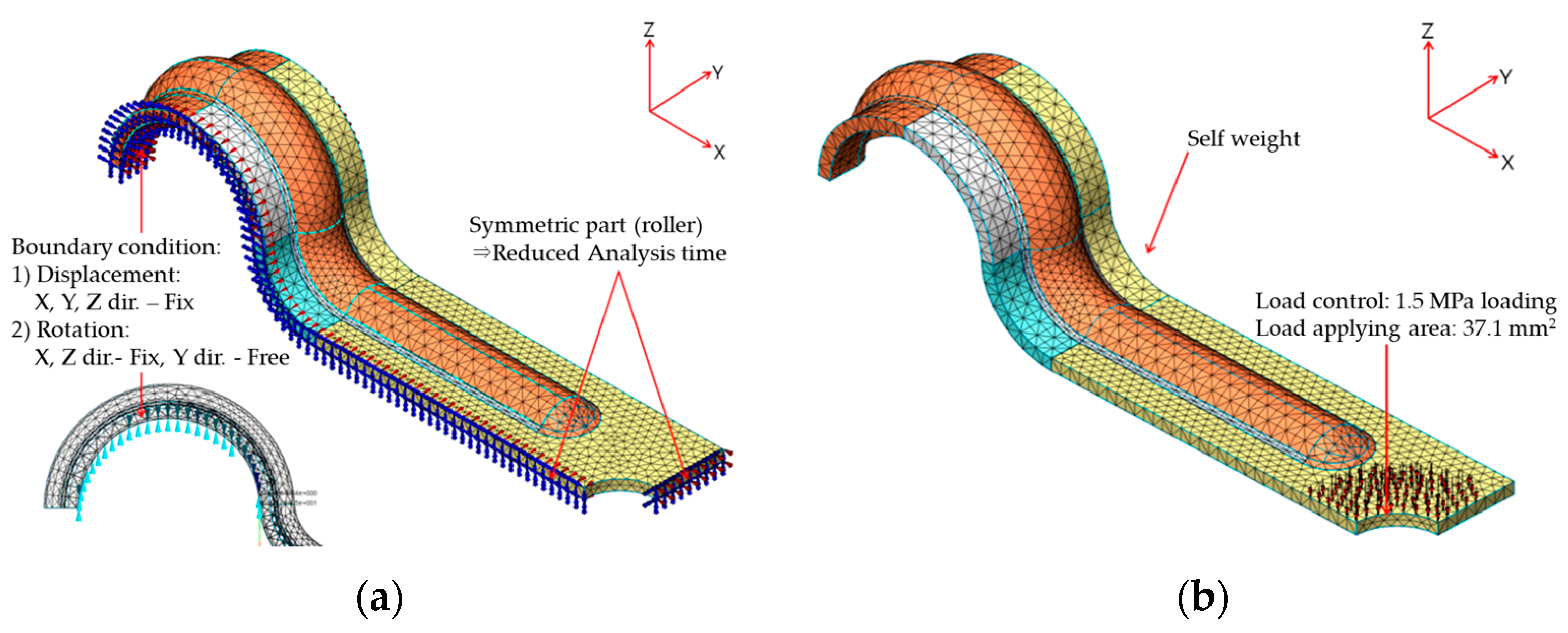
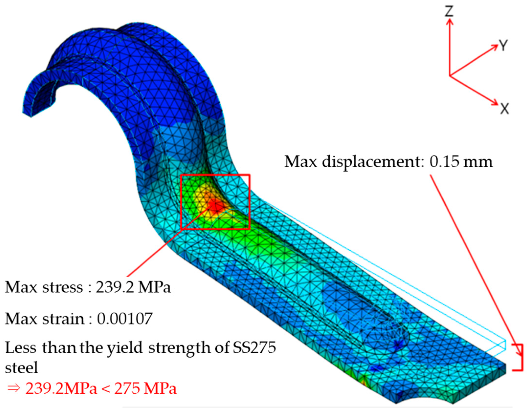
3.2. Finite Element Analysis for Fixing Device

Finite element analysis was conducted to investigate the load acting on the contact surface between the fixing device and the reinforcing bar, as well as to identify the fixture’s most vulnerable component. The shape of the fixture was determined using MIDAS FEA [11], a nonlinear analysis program developed exclusively for bridges and civil structures as part of the MIDAS family of programs, in collaboration with TNO DIANA. MIDAS FEA can conduct linear static analysis and material nonlinearity, heat of hydration, fatigue, crack, and contact analysis.
The analysis model shown in Figure 3 was created with the upper part of the fixing device being biaxially symmetrical at the center. To reduce the analysis time, 3D analysis was conducted by modeling only one-quarter of the structure. Solid 3D elements were modeled to enable both linear and nonlinear analyses that incorporated surface conditions, material nonlinearity, and deformation. The yield strength specified in KS D 3861 [12] was used to verify the safety of the design strength. SS275 steel was chosen for the finite element analysis, using a nominal yield strength of 275 MPa, and a bilinear model was applied. The elastic modulus of the material is 205,000 MPa, and the corresponding yield strain is 0.001341.
According to a prior study by Park [13] of various types of meshes, hexahedral elements can increase the convergence of analysis and accuracy of results when steel materials with complex shapes are involved. However, another study [14] reported no significant difference between the results of analyses of hexahedral and tetrahedral shapes. Given the curved surfaces of the fixing device in this study, hexahedral elements could result in longer analysis times. Therefore, to shorten the analysis time, tetrahedral elements were modeled.
Figure 3a depicts the point condition. In a previous study [15] that analyzed symmetric models, only a part of the model was used to reduce the analysis time, and point conditions were set appropriately on the contact surface. Because the fixed hardware was biaxially symmetrical, only the one-quarter part was modeled, and the support condition was set as a hinge for the Y direction only. This not only shortened the analysis time, but also allowed for the generation of rotational deformation only in the Y-axis direction as the fixing device was simply placed on the steel in the actual connector.
When concrete is poured during construction, a load is transmitted in the Z direction through the bolts used for fixing the formwork (Figure 2). In this study, the load was applied in consideration of the applied area of the bolts, as shown in Figure 3b.
The results of the finite element analysis are presented in Figure 4, with von Mises stress used to evaluate stress distribution with respect to yield. The stress was concentrated in the curved part at the starting point of the load control. The variables affecting the shape of the fixing device were determined by the results of the finite element analysis.

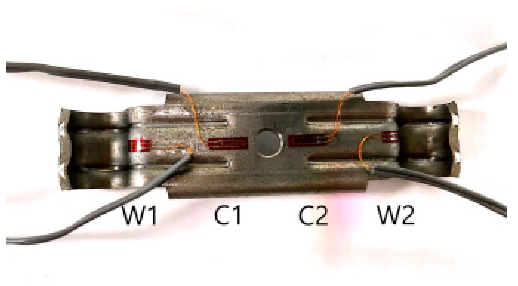
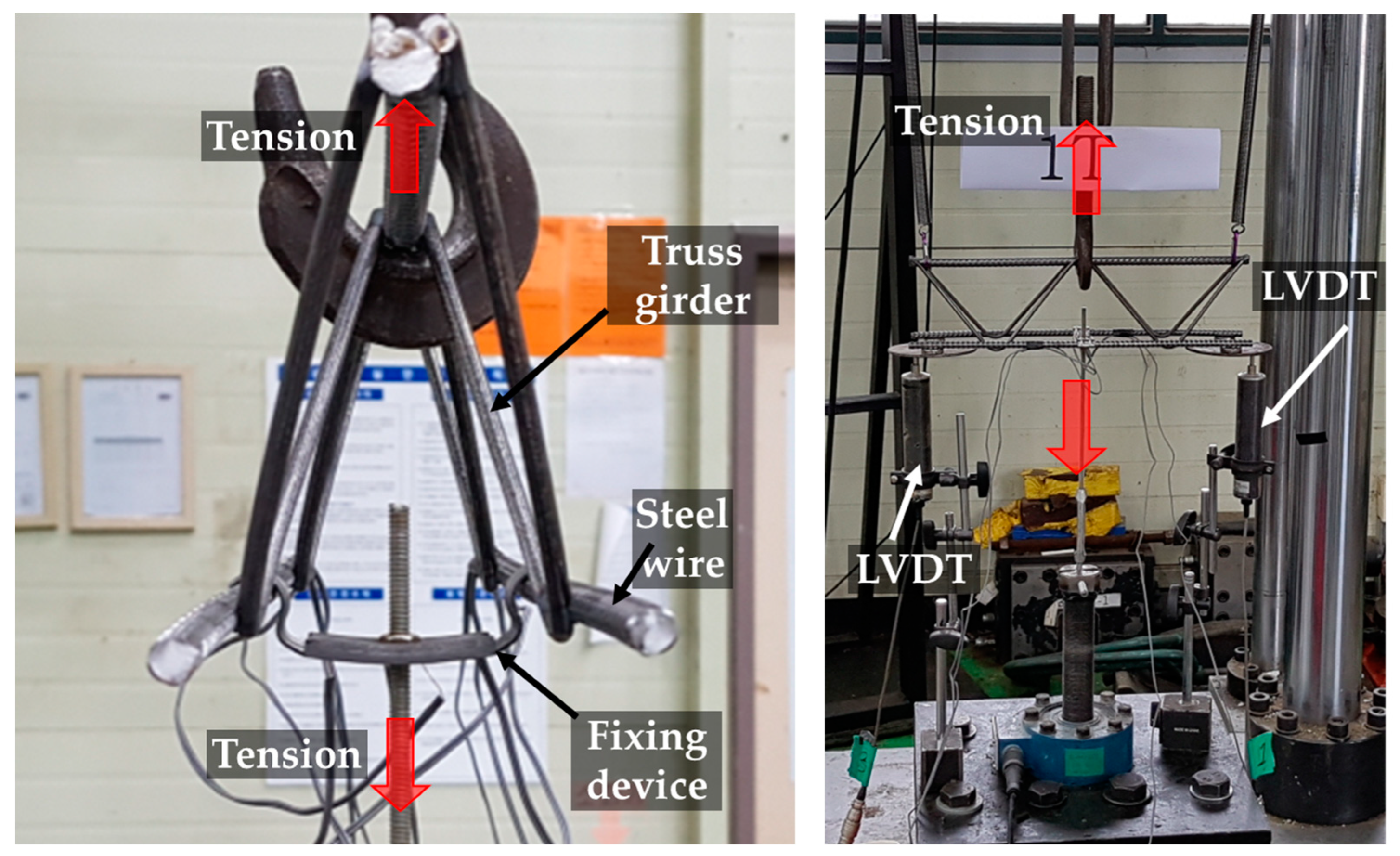
3.3. Anchoring Performance Evaluation of Fixing Device

3.3.1. Test Plan and Specimen Detail

The anchoring performance of the fixing device was assessed by a tensile test using a universal testing machine with a 1000 kN capacity, based on the outcomes of the finite element analysis. Measurements of displacement during the anchoring performance test were taken by installing a linear variable displacement transducer (LVDT) at each end of the lattice girder, and a strain gauge measured the strain of the fixing hardware (Figure 5).
Table 1 lists the experimental design elements of the fixing device anchoring performance test specimens; the main variables comprised the type and thickness of the fixing device. Figure 6 shows the three fixing device types (R, RP, and IR) evaluated in the experiment. The R type shown in Figure 6a introduced two ribs on the bending surface to enhance the steel’s bending resistance. For the RP type shown in Figure 6b, a rib was added to the center of the bending surface from the R type. The IR type in Figure 6c was a test specimen in which two ribs were merged into one thick rib, which exhibited superior bending performance compared with the other two types. The SS275 steel utilized in the experiment had a yield strength of 361 MPa, a tensile strength of 546 MPa, and a yield strain of 0.00172. Figure 7 shows the test setup details. Since it is important for the anchoring performance of the fixing device to maintain its elasticity until the point of maximum strength, the experiment was conducted only up to the maximum strength.

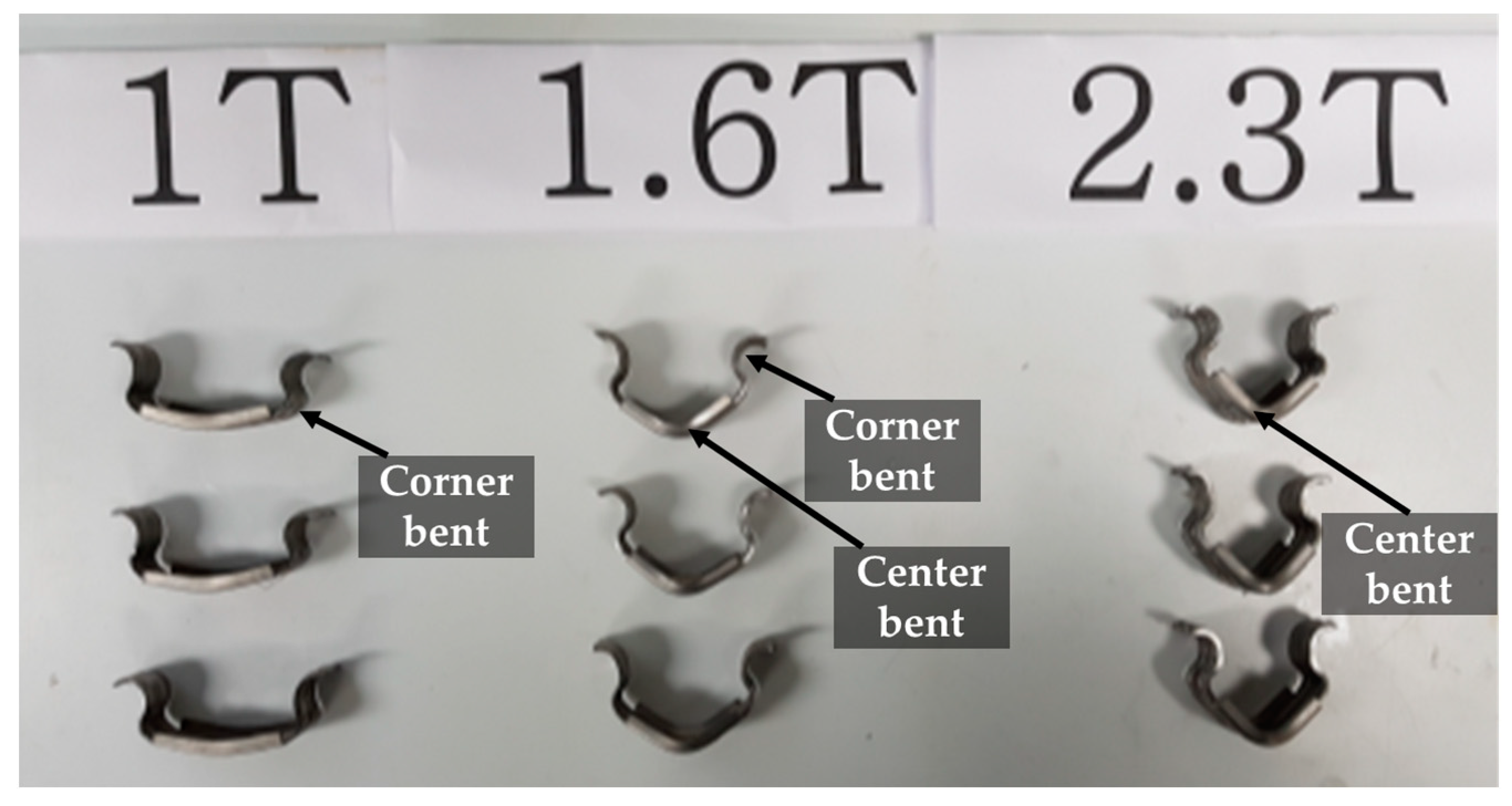
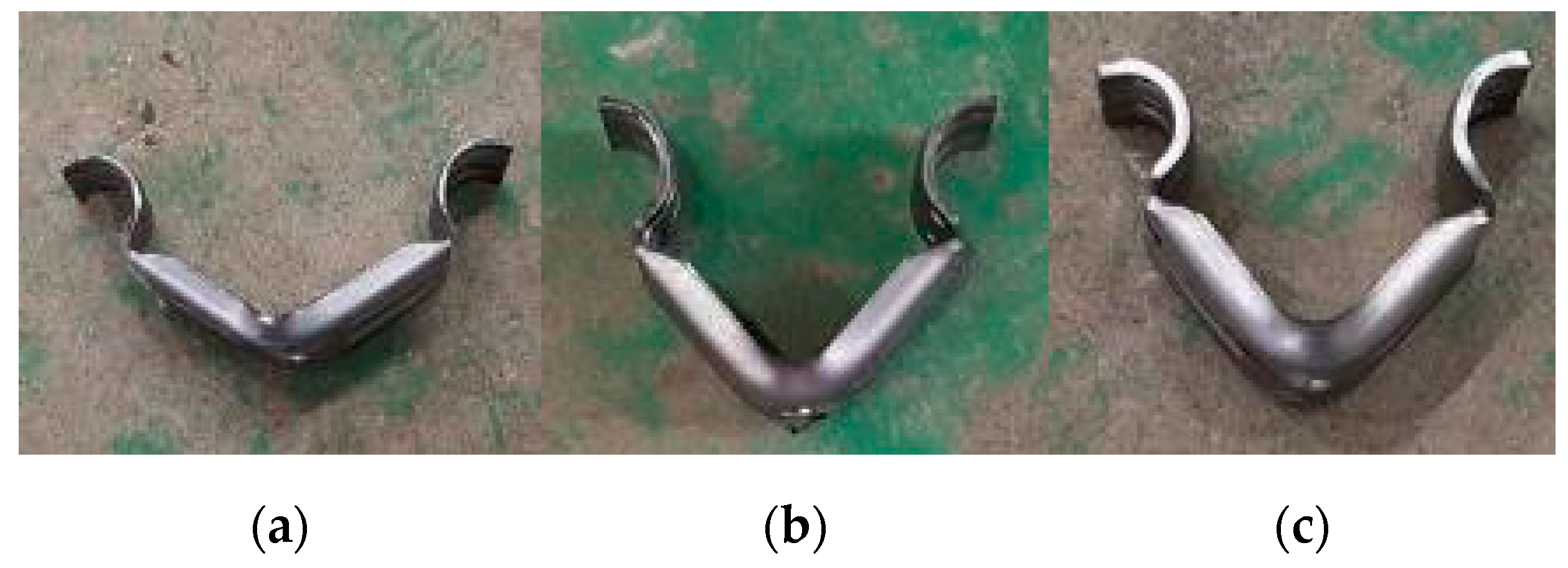
3.3.2. Test Results of Anchorage Performance of the Fixing Device

Table 2 presents the experimental results of the fixing device, while Figure 8 displays the load–displacement curve of the test specimen. The fracture shape corresponding to the fixing device details is illustrated in Figure 9, Figure 10 and Figure 11. The boundary conditions are different from the previous studies [9,10] because the floor panel is made of plywood, so welding is not performed on the hinges, and there is no negative moment at the ends. Accordingly, the truss girder buckling at the end shown in previous studies [9,10] was not found, and the positive moment acted throughout the entire length.
For the R-type fixing device, the maximum load increased with thickness. However, the failure shape and the location of the load concentration differed depending on the thickness (Figure 9). Thinner thicknesses exhibited severe bending at the end portion (W), while both the center and end portions underwent 1.6T deformation. In the thickest 2.3T specimen, the bending was concentrated in the center. Compared with the 1.6T and 2.3T specimens, the strain at the end (W) progressed faster than at the center (C), and the center and end were destroyed almost equally at the same strain in the 1.6T and 2.3T specimens, as depicted in Figure 12a.
When comparing the RP and R types, the maximum load increased, and the stress on the end (W) was reduced, as illustrated in Figure 11b, due to the improved moment of inertia of area resulting from the added end ribs. However, when comparing the R-2.3T and RP-2.0T specimens, the maximum strength did not increase and, in fact, decreased. This suggests that, while the added rib may have prevented stress concentration at the end, it did reduce the thickness.
The IR type demonstrated the highest maximum load, and the yield strength at the center increased to greater than 1 kN. For the 2.0T specimen, the maximum load reached 3.84 kN due to damage to the truss girder caused by the reaction steel rather than damage to the fixing hardware. The results of the fixture test indicate that enhancement of the cross-sectional shape had a positive effect on the anchoring performance of the fixing device, making thickness reduction feasible.

4. Safety Evaluation of Removable Deck Plates during Construction

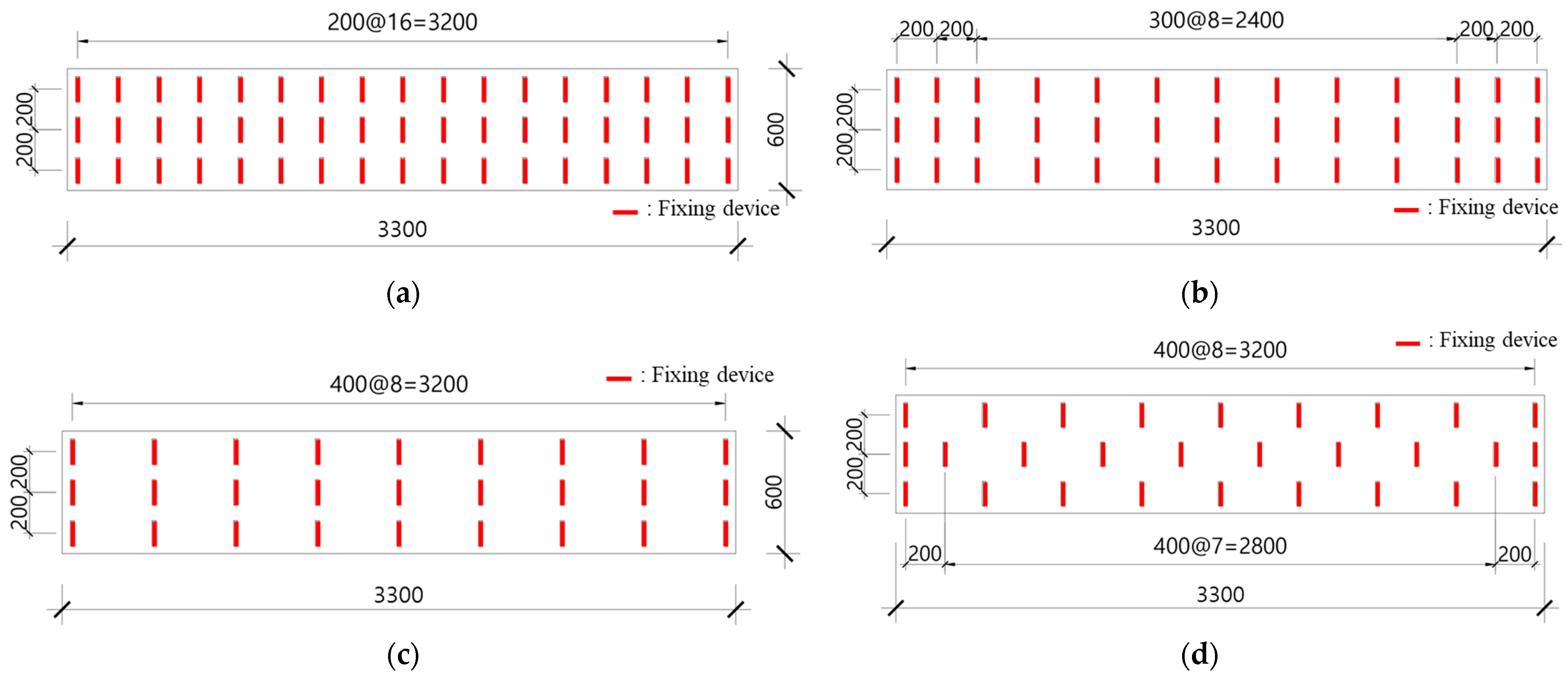
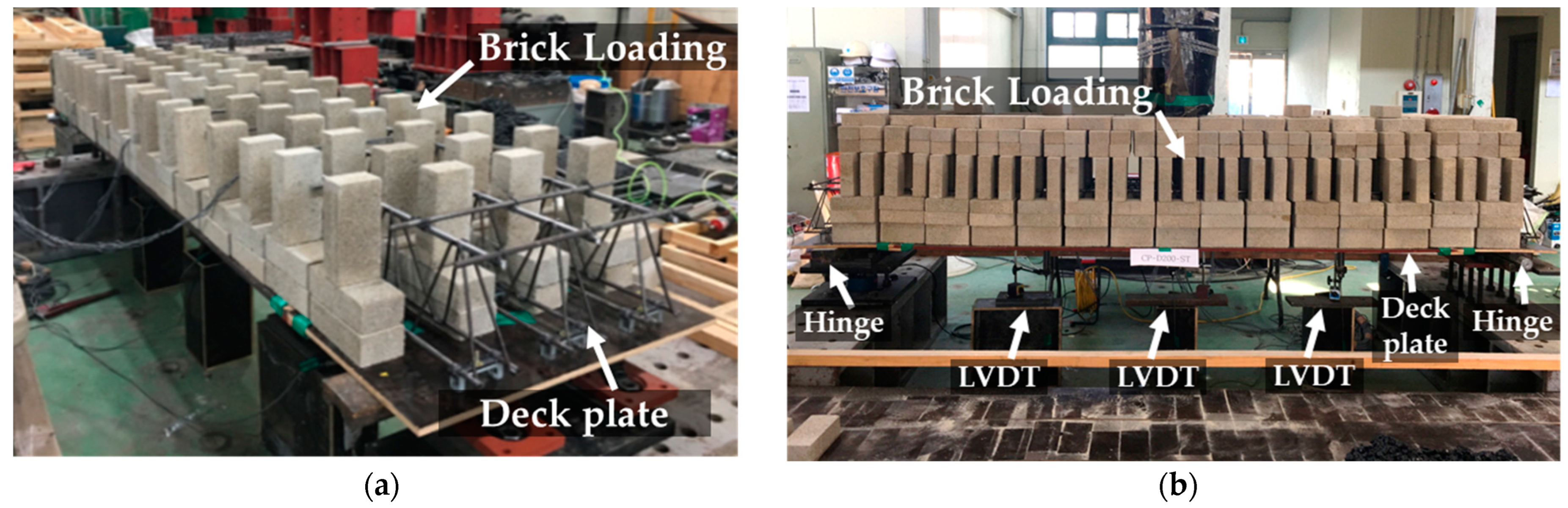
4.1. Construction Load Test Plan

This section evaluated the structural safety of the local destruction of the fixing device for the construction load, which may occur when developing a removable deck plate. To examine the workload during construction and the deflection during slab placement, the installation spacing and installation method of the fixing device were varied. Specimen details are presented in Figure 13, and the experimental variables are listed in Table 3.
Bricks were used to simulate the uniformly distributed load during concrete placement at an actual construction site (Figure 14). The thickness of the deck was set to 250 mm, and the weight of the total deck volume was calculated using a concrete density of 23 kN/m3, as suggested by KDS 21 50 00:2022 [16]. A concentrated load of 1.5 kN was applied to the maintenance workers. The point-to-point distance was set to 3000 mm by installing hinges 150 mm inside both sides of the specimen. To measure the amount of deflection according to the load, an LVDT was installed at the fourth place from the distance between the points, and strain gauges were attached to the upper and lower reinforcing bars and the fixing device, as detailed in Table 3.

4.2. Construction Load Test Results

4.2.1. Load–Displacement Relationship

Table 4 depicts the test results, and Figure 15 displays the load–displacement curve for each specimen. The construction load was determined by adding a concrete dead weight, a working load of 2.5 kN/m2, and a concentrated load of 1.5 kN on the worker, as suggested in the formwork and shore design standard (KDS 21 50 00) [16]. The load during construction was estimated as a coefficient load, considering the safety factor, with the concrete dead load treated as a dead load and the working load, calculated as 1.2D + 1.6L, as a live load. The total load amounted to 23.98 kN when computing the coefficient load, and up to 24.2 kN was applied to examine the brick’s weight and its behavior after reaching the maximum load.
The maximum strength of the member and the displacement at that time can be derived through the load–displacement relationship, and the stiffness of the member can be evaluated using the slope. As shown in Figure 15, the stiffness decreased as the spacing of the fixing device increased, but the difference was not large. Unlike the other three specimens, the D400-ST specimen had significantly reduced stiffness, and the staggered arrangement of D400-CR showed the same level of stiffness as D200-ST and D300-ST. Accordingly, by changing the installation pattern of the fixing device, it will be possible to improve the bending performance of the detachable deck plate during construction.
The experimental results revealed that the D200-ST specimen, with the fixing device interval arranged in a straight line at 200 mm, exhibited stable behavior due to the adequate number of fixing devices. The maximum displacement was 8.8 mm. Furthermore, the slope of the load–strain curve remained constant until the construction load was applied, indicating that the specimen behaved within the elastic region. This indicates that sufficient safety was ensured, as the specimen did not exhibit a rapid decrease in stiffness due to the failure of the fixing device.
Although it is possible to compare the difference in stiffness of each specimen based on the test results, there is a limit to quantitatively evaluating the stiffness of the specimen because an accurate uniformly distributed load is not applied due to the nature of the experiment. Therefore, in future studies, a method that can accurately simulate uniformly distributed loads is needed.

4.2.2. Load–Strain Relationship

To evaluate structural safety during construction, it is necessary for all elements of a removable deck plate to remain in an elastic state while the construction load is applied. Serviceability, such as deflection, assumes that the member is within the elastic region. KDS 14 20 00 [17] limits L / Δ c to 240 for floor supporting nonstructural elements that are not likely to be damaged by excessive deflection. As shown in the experimental results presented in Table 4, there is no abnormality in structural safety because all specimens are within the deflection limit. In this section, for a more detailed analysis, the yield of the fixing device is evaluated using the load–strain relationship presented in Figure 16.
The strains of the tensile and compressive reinforcing bars in the D200-ST specimen were within 16% of the yield strain and changed linearly. For the fixing device, a rapid increase in strain occurred due to the concentrated load at the 21.6 kN point after the applied load exceeded 10 kN, but all strains corresponded to the initial section of the elastic range, which was less than 20% of the yield strain. These results indicate that all elements remained in an elastic state during construction, confirming the structural safety of the removable deck plate (Figure 16).
In the case of the D300-ST specimen, the upper and lower reinforcing bars were in the initial section of the elastic range, similar to the D200-ST specimen. Although the strain of the fixing device increased compared with the D200-ST specimen, it was within the initial section of the elastic range. The maximum strain of the fixing device was observed at 0.0009 when a concentrated load was applied, which was 44% of the yield strain. This indicates that the structural safety of the specimen was not compromised.
The D400-ST specimen showed a high displacement at maximum loads due to a smaller number of fixing devices, which resulted in a higher strain of the fixing device compared with other specimens. Although the tension and compression rebars were in the initial section of the elastic range at maximum load, the strain in the central part of the fixed steel was approximately 0.0013, which was 65.9% of the yield strain. Similarly, in the D400-CR specimen, the strain of the fixing device was the greatest, at 0.0017 (see Table 5).

5. Flexural Performance of Reinforced Concrete Deck Slab

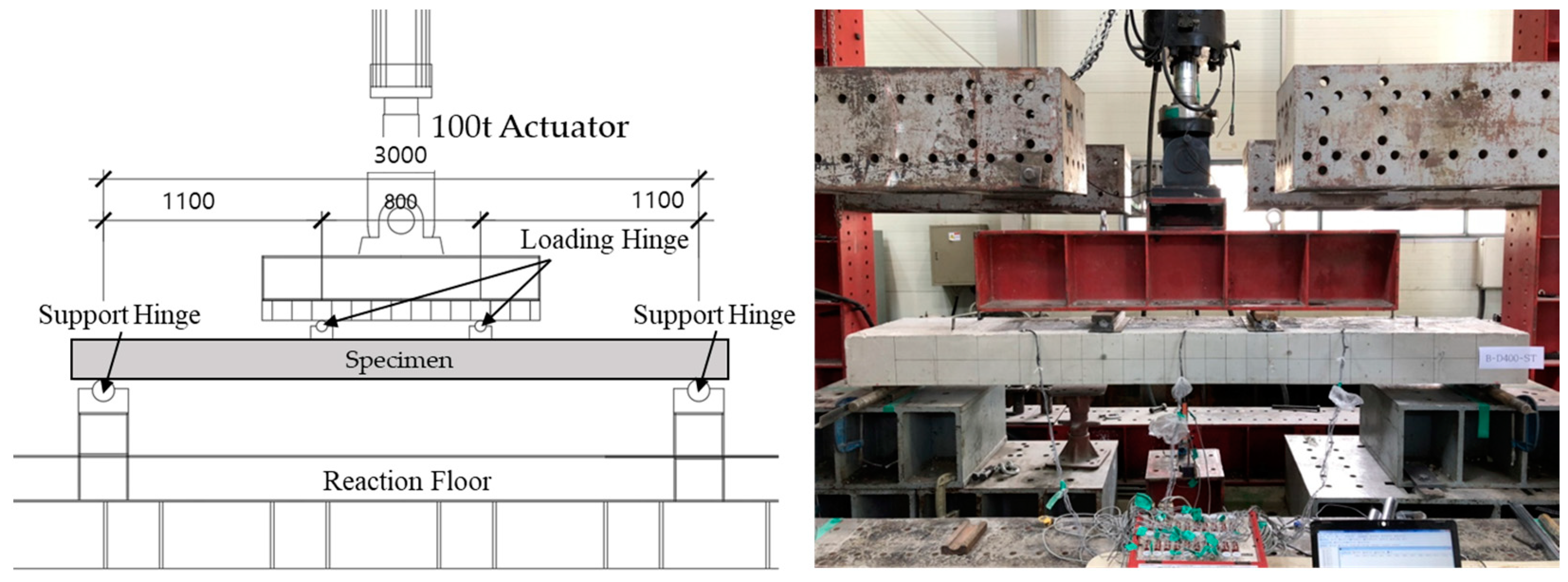
5.1. Construction Load Test Plan

A slab specimen was fabricated using a truss girder and fixed hardware to evaluate the flexural performance after placement. A four-point load was applied using an actuator with a capacity of 1000 kN, as shown in Figure 17 and Figure 18, using the fixed hardware installation interval as a variable. The slab specimens were divided into 200, 300, and 400 mm installation intervals for the fixed hardware (Table 6). The arrangement was divided into straight and staggered types, as in the casting deflection test, with a point distance of 3000 mm.
A bending test was used to investigate the effects of fixed hardware spacing and installation type on flexural performance. The bending specimen plan is detailed in Table 6, where “B” represents the bending test of the developed product, “D” represents the interval of the fixed hardware, and “ST” and “CR” represent the type of fixed hardware installation. The typical bending test status is depicted in Figure 18. The results of this study provide insight into the relationship between fixed hardware spacing and installation type on the flexural performance of products.

5.2. Material Test Results

A compressive strength test was conducted on a concrete specimen manufactured according to KS F 2403 [18] with a size of Φ100 × 200 and cured for 28 days. Tests performed on three specimens found that the average compressive strength was 37.06 MPa, which exceeded the planned design standard compressive strength of 24 MPa.
Reinforcing bars made of D10 SD500 and D13 SD500 were used for the bottom and upper sections, respectively. When reinforcing bars were tested according to KS B 0802 [19], their yields and tensile strengths exceeded the nominal values. The yield strength of the D10 rebar was 532 MPa, with a tensile strength of 620 MPa, while the yield strength of the D13 rebar was 483 MPa, with a tensile strength of 572 MPa.

5.3. Flexural Performance Test Results

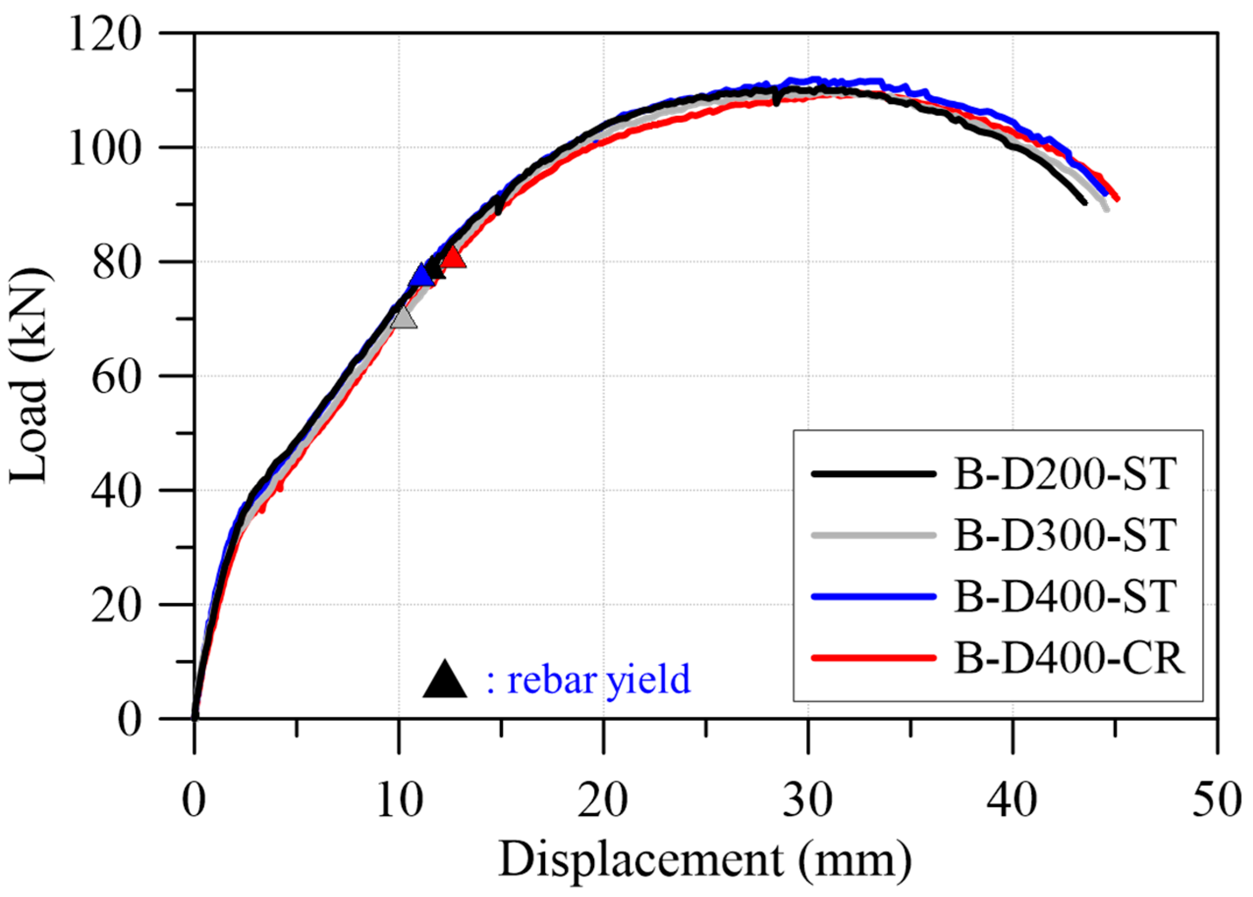
5.3.1. Load–Displacement Relationship and Crack Pattern

Table 7 presents the results of the test, with the load shown excluding the weight of the specimen. Figure 19 depicts the load–displacement curve of the specimen. The nominal flexural strength in the graph was calculated by subtracting the value of the dead weight.
As a result of conducting four-point loading experiments to compare and examine the difference in bending behavior of the deck slab specimens due to the difference between the fixing device installation interval and the specimen point distance, all specimens showed typical bending failure patterns due to bending cracks in the center and crushing of the upper part. As shown in Figure 20, the fixing device installation interval did not significantly affect the change in the load–displacement curve. In the flexural behavior, the reinforcing bar is subjected to tensile force due to the bond between the concrete and the reinforcing bar. During the flexural behavior, the reinforcing bar seems to receive sufficient tensile force regardless of the details of the fixing device.

5.3.2. Load-Strain Relationship

The behavior of the reinforcing bars and fixings under load is illustrated in Figure 21. The reinforcing bar was deformed beyond yields until failure after reaching maximum strength. The fixing device, being bound to the inside of the concrete, experienced almost no deformation, and there was no discernible difference in flexural behavior due to the spacing of the fixed hardware or the distance between the support points. Moreover, there was minimal variation in the flexural behavior of all specimens, with both groups exhibiting elastic behavior within the service load.

6. Conclusions

A variable removable deck plate was developed to improve product quality and construction efficiency and to evaluate the safety of the product during construction and use. Tensile tests, deflection tests for deck plate construction loads, and bending performance evaluations produced the following conclusions:
(1)
The anchorage performance test of the fixing device showed that the IR test specimen exhibited 7% to 25% greater ultimate strength compared with the R and RP types, making it the most effective shape. The improvement of the cross-sectional shape enabled structural performance improvement and steel thickness reduction.
(2)
A deflection test for construction determined that the maximum spacing of the fixing device should be less than 300 mm when considering design safety. Staggered placement at 300 mm intervals is recommended as the deflection during construction can be reduced if staggered arrangement is performed rather than in line arrangement. This suggests a need to secure a sufficient safety factor for detailed devices in the entire deck plate in case of sagging, particularly in places where there is a concern about concentrated loads by casting load and equipment in future design and on-site construction.
(3)
The strain of the fixing device in the flexural performance test was found to be in an elastic state, while all reinforcing bars yielded before maximum strength were reached and exhibited sufficient deformation. The installation method and spacing of the fixing device, therefore, have little to do with bending performance.
(4)
The FEA performed in this study was used only as a tool to set the experimental parameters. Although the most effective shape was found through the experimental results, finite element analysis under various conditions, such as thickness, width, and curvature, for shape optimization was not performed. Therefore, future studies should apply finite element analysis to various variables based on the experimental results to identify the optimal height and width of IR-type ribs so that the experimental results can be generalized.

Author Contributions

Original draft preparation and editing, performing tests, and investigations, H.-S.J.; validation and editing, M.Y.; supervision and review writing, C.-S.C. All authors have read and agreed to the published version of the manuscript.

Funding

This research was supported by the Basic Science Research Program through the National Research Foundation of Korea (NRF) funded by the Ministry of Education (RS-2023-00207763).

Institutional Review Board Statement

Not applicable.

Informed Consent Statement

Not applicable.

Data Availability Statement

Data are contained within the article.

Conflicts of Interest

The authors declare no conflict of interest.

References

  1. Son, D.H.; Bae, B.I.; Lee, M.S.; Lee, M.S.; Choi, C.S. Flexural Strength of Composite Deck Slab with Macro Synthetic Fiber Reinforced Concrete. Appl. Sci. 2021, 11, 1662. [Google Scholar] [CrossRef]
  2. Langarudi, P.A.; Ebrahimnejad, M. Numerical Study of the Behavior of Bolted Shear Connectors in Composite Slabs with Steel Deck. Structures 2020, 26, 501–515. [Google Scholar] [CrossRef]
  3. Subhani, M.; Kabir, M.I.; Al-Ameri, R. Strengthening of Steel-Concrete Composite Beams with Composite Slab. Steel Compos. Struct. 2020, 34, 91–105. [Google Scholar]
  4. Bae, K.W.; Lee, S.S.; Park, K.S. An Experimental Study on the Flexural Behavior for the Slabs Using the Suspending Deck Plate. J. Korean Soc. Steel Constr. 2013, 25, 25–34. [Google Scholar] [CrossRef] [Green Version]
  5. John, K.; Ashraf, M.; Weiss, M.; Al-Ameri, R. Experimental Investigation of Novel Corrugated Steel Deck under Construction Load for Composite Slim-Flooring. Buildings 2020, 10, 208. [Google Scholar] [CrossRef]
  6. Hong, E.-A.; Chung, L.; Paik, I.-K.; Yun, S.-H.; Cho, S.-H. Structural Performance and Usability of Void Slab Established in T-deck Plate. J. Korea Concr. Inst. 2012, 24, 677–684. [Google Scholar] [CrossRef] [Green Version]
  7. Lee, J.-E.; Kim, B.-Y.; Jung, B.-J. Evaluation of Structural Safety and Economic Feasibility for Removable Steel Plate Eco Deck Plate. J. Archit. Inst. Korea Struct. Constr. 2014, 30, 3–10. [Google Scholar]
  8. Lee, H.-J.; Yang, K.-H.; Kim, S.; Hong, J.-K.; Kim, D.-H.; Mun, J.-H. Deflection Test of Wire-Integrated Steel Deck Plates with Various End Details. Materials 2023, 16, 2251. [Google Scholar] [CrossRef] [PubMed]
  9. Kim, S.B.; Kang, M.J.; Kim, S.S. An experimental study on structural performance evaluation of steel wire-integrated deck plate. Int. J. Steel Struct. 2015, 15, 945–958. [Google Scholar] [CrossRef]
  10. Shin, J.; Lee, J.; Lee, Y.; Kim, B. Experimental and Numerical Investigation on Structural Performance of Steel Deck Plate Bolted with Truss Girder. Appl. Sci. 2019, 9, 3166. [Google Scholar] [CrossRef] [Green Version]
  11. MIDAS IT. MIDAS/FEA Users Manual; MIDAS IT: Seongnam-si, Republic of Korea, 2015. [Google Scholar]
  12. Korean Agency for Technology and Standards. KS D 3861; Rolled Steels for Building Structures. Korean Agency for Technology and Standards: Seoul, Republic of Korea, 2021; pp. 1–19.
  13. Park, J.H. Nonlinear Finite Element Analysis of Prestressed Composite Beams with Discontinued Webs. Master’s Thesis, University of Seoul, Seoul, Republic of Korea, 2013. [Google Scholar]
  14. Earij, A.; Alfano, G.; Cashell, K.; Zhou, X.M. Nonlinear three-dimensional finite-element modelling of reinforced-concrete beams: Computational challenges and experimental validation. Eng. Fail. Anal. 2017, 82, 92–115. [Google Scholar] [CrossRef]
  15. Genikomsou, A.S.; Polak, M.A. Finite element analysis of punching shear of concrete slabs using damaged plasticity model in ABAQUS. Eng. Struct. 2015, 98, 38–48. [Google Scholar] [CrossRef]
  16. Ministry of Land, Infrastructure and Transport. KDS 21 50 00; Formwork and Shoring Design Code. The Korea Communications Standards Commission: Seoul, Republic of Korea, 2022. (In Korean)
  17. Ministry of Land, Infrastructure and Transport. KDS 14 20 00; Structural Concrete Design Cosede. The Korea Communications Standards Commission: Seoul, Republic of Korea, 2022. (In Korean)
  18. Korean Agency for Technology and Standards. KS F 2403; Standard Test Method for Making Concrete Specimens. Korean Agency for Technology and Standards: Seoul, Republic of Korea, 2019; pp. 1–8. (In Korean)
  19. Korean Agency for Technology and Standards. KS B 0802; Method of Tensile Test for Metallic Materials. Korean Agency for Technology and Standards: Seoul, Republic of Korea, 2003; pp. 1–9. (In Korean)
Figure 1. Schematic diagram of the research procedures.
Applsci 13 04903 g001
Figure 2. Details of the fixing device: (a) composition of the fixing device; (b) combination of deck plate and fixing device.
Applsci 13 04903 g002
Figure 3. FEA modeling of fixing device: (a) boundary condition; (b) load condition.
Applsci 13 04903 g003
Figure 4. FEA analysis results.
Applsci 13 04903 g004
Figure 5. Attached strain gauge in fixing device.
Applsci 13 04903 g005
Figure 6. Fixing device details: (a) R type; (b) RP type; (c) IR type.
Applsci 13 04903 g006
Figure 7. Test setup.
Applsci 13 04903 g007
Figure 8. Load–displacement relationship of the fixing device.
Applsci 13 04903 g008
Figure 9. R series failure shape.
Applsci 13 04903 g009
Figure 10. RP series failure shape: (a) RP-1.2T; (b) RP-1.6T; (c) RP-2.0T.
Applsci 13 04903 g010
Figure 11. IR series failure shape: (a) IR-1.6T; (b) IR-2.0T.
Applsci 13 04903 g011
Figure 12. Load–strain relationship: (a) R series; (b) RP series; (c) IR series.
Applsci 13 04903 g012
Figure 13. Specimens’ detail for the construction load test: (a) D200-ST; (b) D300-ST; (c) D400-ST; (d) D400-CR.
Applsci 13 04903 g013
Figure 14. Test configuration for construction load test: (a) 50% of peak load; (b) peak load.
Applsci 13 04903 g014
Figure 15. Load–displacement of construction load test.
Applsci 13 04903 g015
Figure 16. Load–strain relationship of construction load test: (a) B-D200-ST; (b) B-D300-ST; (c) B-D400-ST; (d) B-D400-CR.
Applsci 13 04903 g016
Figure 17. Flexural performance test specimen details: (a) plan view; (b) section view (unit: mm).
Applsci 13 04903 g017
Figure 18. Flexural test specimen setup (unit: mm).
Applsci 13 04903 g018
Figure 19. Flexural performance test failure pattern: (a) B-D200-ST; (b) B-D300-ST; (c) B-D400-ST; (d) B-D400-CR.
Applsci 13 04903 g019
Figure 20. Load–displacement relationship.
Applsci 13 04903 g020
Figure 21. Load–strain relationship: (a) bottom bar; (b) fixing device.
Applsci 13 04903 g021
Table 1. Specifications of fixing device for anchoring performance test.
SpecimensThickness
(mm)
Type
R-1.0T-11.0R
(rib)
R-1.0T-2
R-1.0T-3
R-1.6T-11.6
R-1.6T-2
R-1.6T-3
R-2.3T-12.3
R-2.3T-2
R-2.3T-3
RP-1.2T-11.2RP
(rib plus)
RP-1.6T-11.6
RP-1.6T-2
RP-2.0T-12.0
RP-2.0T-2
IR-1.6T-11.6IR
(integrated rib)
IR-2.0T-12.0
Table 2. Experimental results of the fixing device anchorage test.
SpecimenYield LoadPeak Load
Load
(kN)
Displacement
(mm)
Yield
Position
Load
(kN)
Displacement
(mm)
R-1.0T-10.4812.35C0.7820.18
R-1.0T-20.357.95W0.7822.8
R-1.0T-30.328.510.7822.5
R-1.6T-10.6511.79C1.63
R-1.6T-20.586.731.7334.82
R-1.6T-30.68.541.7234.8
R-2.3T-11.310.42C3.5562.23
R-2.3T-21.1816.443.343.01
R-2.3T-31.2511.83.3245.39
RP-1.2T-10.5912.15C0.8627.44
RP-1.6T-10.8213.142.0141.76
RP-1.6T-20.511.46
RP-2.0T-10.9310.362.5242.04
RP-2.0T-20.71.98
IR-1.6T-11.05C2.15
IR-2.0T-11.543.84
Table 3. Specification of specimens.
SpecimenSpacing of Fixing Device
(mm)
Fixing Device
Installation Type
D200-ST200ST
(straight)
D300-ST300
D400-ST400
D400-CR400CR
(cross)
Table 4. Construction load test results.
SpecimenPeak Load
(kN)
Δ c
(mm)
L / Δ c
D200-ST24.28.8341
D300-ST8.4357
D400-ST11.9252
D400-CR10.4288
L: Clear span, Δ c : midspan displacement at maximum load.
Table 5. Strain of specimens.
SpecimenAt Maximum Load
Tensile RebarFixing Device
D200-ST0.000320.0004
D300-ST0.000300.0009
D400-ST0.00030.0013
D400-CR0.000250.0017
Table 6. Flexural performance specimen details.
Specimen IDLengthWidthThicknessShear Span
Ratio
Spacing of
Fixing Device
Fixing Device
Installation Type
Deck Plate
Type *
(mm)(mm)(mm)(mm)
B-D200-ST33006002504.4200ST
(straight)
D200-ST
B-D300-ST300D300-ST
B-D400-ST400D400-ST
B-D400-CRCR
(cross)
D400-CR
*: Specimen ID used in the construction load test.
Table 7. Flexural performance test results.
Specimen IDYield PointPeak Load
Load
(kN)
Disp.
(mm)
Moment
(kN-m)
Rotation
(×10−2 rad)
Load
(kN)
Disp.
(mm)
Moment
(kN-m)
Rotation
(×10−2 rad)
B-D200-ST89.414.849.21.34108.430.759.62.79
B-D300-ST81.611.944.91.08107.629.459.22.67
B-D400-ST84.413.246.41.20109.730.260.32.75
B-D400-CR92.816.851.11.53107.432.659.02.96
Disclaimer/Publisher’s Note: The statements, opinions and data contained in all publications are solely those of the individual author(s) and contributor(s) and not of MDPI and/or the editor(s). MDPI and/or the editor(s) disclaim responsibility for any injury to people or property resulting from any ideas, methods, instructions or products referred to in the content.

