Article

Effect of Laser Surface Treatment on the Corrosion Resistance of Zircaloy-4 at High Temperature

School of Nuclear Science and Technology, Xi’an Jiaotong University, Xi’an 710049, China
*
Author to whom correspondence should be addressed.
Appl. Sci. 2024, 14(12), 4977; https://doi.org/10.3390/app14124977
Submission received: 9 May 2024 / Revised: 1 June 2024 / Accepted: 3 June 2024 / Published: 7 June 2024

Abstract

:
A 700 V pulsed laser was used for the surface treatment of Zircaloy-4. Phases including the treatment layer, morphology and the distributions of alloying elements of the treatment layer were detected via X-ray diffraction (XRD), scanning electron microscope (SEM) and transmission electron microscope (TEM). The results showed that the laser surface treatment (LST) layer is also α-Zr phase layer, the morphology of the treatment layer was “cauliflower-like” and the Fe-Cr precipitates in the LST layer were dissolved. The corrosion tests of the LST and the no-laser surface treatment (NLST) specimens were conducted in steam at 1100 °C using TGA (NETZSCH STA 449 F). The results showed that LST can enhance the corrosion resistance of the Zircaloy-4 in high-temperature steam. More microcracks distributed in the oxide film formed on the NLST specimen than on the LST specimen. And the volume fraction of the tetragonal zirconia (t-ZrO2) phase in the oxide film on the surface of the LST specimen was higher than that of NLST specimen. The main reason for this phenomena could be attributed to the dissolving Fe-Cr precipitates and higher solid solution of Fe and Cr in the laser treatment layer.

1. Introduction

After the Fukushima nuclear power plant accidents in 2011, a number of studies on accident-tolerant fuels (ATFs) have been conducted to cope with loss-of-coolant accidents (LOCAs) [1,2,3]. Up to now, coating technology is mainly used to prepared coated zirconium alloy cladding. Plasma electrolytic oxidation, magnetron sputtering vacuum arc plasma deposition, arc ion plating, cold spraying, a special physical vapor deposition system and laser beam scanning are widely utilized deposition technologies. Nitride coatings, MAX phase coatings, carbide coatings, pure metal coatings and high-entropy alloy coatings are the main coatings [4,5,6,7,8,9,10]. To the best of our knowledge, the metallic Cr coating is considered to be the best choice for pressurized water reactor (PWR) due to their optimal corrosion resistance in high-temperature steam [4,10,11,12,13,14,15,16].
However, many kinds of defects are formed during the corrosion of Cr-coated zirconium alloys in steam at high temperature. For example, many pores are formed at the interface of Cr2O3 and Cr due to the Kirkendall effect [11,16,17,18,19,20]. Small cavities are also present inside the Zr substrate and the ZrCr2 layer adjacent to the ZrCr2/Zr interface due due to the Kirkendall effect [16,19,21]. Bubbles are formed in Zr substrate near the Cr-Zr layer. And nanocavities appear into the Cr2O3 grains [19,20,22]. Moreover, Cr diffuses into the Zr matrix to form Zr(Cr) solid solution and brittle ZrCr2 precipitation [7,23,24]; ZrCr2 is about five times harder than the Zr matrix, and the modulus of elasticity of ZrCr2 is 1.5 times lower that of the Zr matrix [25,26]. During the corrosion, ZrCr2 tends to cause crack formation; then, these cracks extend to the coating, and the matrix causes the coatings to lose their protectiveness [27,28]. Consequently, the corrosion rate is enhanced. Based on the discussion presented above, although a metallic Cr coating is a promising option for practical application, it also has many deficiencies. We can sum up two key points that cause the coatings lose their effectiveness. One is that Cr is a heterogeneous element to Zr. Another is the interface that forms between the coating and the Zr matrix. So, we must think about that whether it is possible to achieve the effect of improving the high-temperature corrosion resistance of zirconium alloy cladding without coatings by only treating the surfaces of zirconium alloy cladding, so that neither heterogeneous elements can be introduced nor obvious interfaces can be present, thus avoiding the above-mentioned problems of Cr coatings during actual high-temperature corrosion, which is the main starting point of this work.
Some works on the effect of laser surface treatment (LST), as one type of surface treatment technology, on the corrosion resistance of zirconium alloys have been reported. Zhao et al. [29] found that LST can significantly increase the nodular corrosion resistance of the Zircaloy-4 plate specimens. Yang et al. [30] firstly prepared an oxide film on the surface of a Zr-1Nb alloy via the micro-arc oxidation (MAO) method because the oxide film layer formed by MAO was loose and the surface was not flat. The subsequent treatment of the material surface using s laser was expected to improve the surface state of zirconium alloy tubes after MAO. The results showed that the specimens treated with a laser of 500 mJ and a scanning speed of 0.13 mm/s achieved the most obvious improvement in corrosion resistance of the specimens corroded in LiOH aqueous solution. It was concluded that this was mainly related to the fact that LST could reduce the surface roughness and increase the density of the oxide film and promoted the transformation of the monoclinic zirconia (m-ZrO2) phase to the tetragonal zirconia (t-ZrO2) phase. Andersson et al. [31] reported that LST can enhance the nodular corrosion resistance of Zircaloy-2 and Zircaloy-4 corroded in steam at 500 °C. Lee et al. [32] found that melting Nb on the surface of Zircaloy-4 using a laser can enhance the hardness of Zircaloy-4 and the corrosion resistance of Zircaloy-4 in chloride solution, but it can deteriorate the corrosion resistance of Zircaloy-4 corroded in steam at 400 °C. In addition, Chai et al. [33,34], Tang et al. [35], Wu et al. [36] and Liu et al. [37] have reported the effect of LST on the hardness, abrasive resistance and microstructures of the zirconium alloys, but they did not carry out more studies on LST’s effect on corrosion resistance in high-temperature steam.
Based on the above discussion, LST can affect the corrosion resistance of zirconium alloys, but the effect of LST on corrosion resistance in high-temperature steam during LOCAs has rarely been reported. In our work, LST was conducted on the Zircaloy-4 plate specimens, which were then corroded in steam at 1100 °C. The morphology and phase constituents, the element distributions of the treatment layer and the morphology of oxide film have been observed, and the mechanism of the effect of LST on the corrosion resistant of Zircaloy-4 in high-temperature steam has also been discussed.

2. Experimental Procedures

Plate-like Zircaloy-4 (Zr-1.34Sn-0.19 Fe-0.11Cr, wt.%) with a thickness of 1 mm was used in this study. The surface of the material was treated with a Nimma-900 pulsed laser with a laser voltage of 700 V, a frequency of 10 HZ and a laser energy of 208 mJ. A schematic diagram of the LST process is shown in Figure 1. The spot size of the laser was ~0.8 mm. To prevent the specimen from oxidizing during the LST process, Ar gas was continuously blown onto the surface of the specimen at a flow rate of 10 L per minute (LPM) as a protection gas. During the process of LST, the laser beam and Ar gas were fixed, but the moving rate of the specimen along X-axis was 3.628 mm/s, while the moving step of the specimen along Z-axis was 0.5 mm. The laser-treated plate-like specimen was cut into 15 mm × 10 mm sheet-like specimens. Next, samples of 800#, 1000#, and 1200# sandpaper were used to remove the cutting marks. Then, ultrasonic cleaning was used to clean the specimens. The surface morphologies of the specimens were observed using a NOVEL optical microscope (Jiangnan Yongxin, Nanjing, China).
A thermogravingmetric analysis (NETZSCH STA 449F) instrument was used to carry out the corrosion test for the 15 mm long specimens in steam at 1100 °C and a heating rate of 20 °C/min. At the furnace temperature of 350 °C, a gas mixture containing steam with a mass flow rate of 2 g/h and Ar gas with a volume flow rate of 170 mL/min was injected into the furnace. After the furnace temperature reached 1100 °C, the specimens were held at this temperature for 2 h. The corrosion test was then completed, and the furnace was cooled down to room temperature at a rate of 10 °C/min. Specimens heated to 600 °C and 1100 °C in this instrument, according to the above corrosion process, were identified to study the mechanism behind the effect of LST on the corrosion resistance of Zircaloy-4. X-ray diffraction (XRD, Bruker D8, Brooke Scientific Instruments, Darmstadt, Germany) was used to detect the phases on the LST layer and the phases in oxide films. The 2θ angle range was 20–90°, and the scanning step was 0.02°. The cross-sectional morphologies of the LST Zircaloy-4 specimen and the oxide films of the LST and the NLST Zircaloy-4 specimens, as well as the element distribution of the treatment layer, were observed using a scanning electron microscope (SEM) and a transmission electron microscope (TEM), respectively. Prior to observing the cross-sectional morphology of the LST layer using SEM, the specimen was pickled in a mixed solution of 10%HF + 30%HNO3 + 30%H2SO4 + 30%H2O (in volume). The cross-sectional oxide specimen for TEM was fabricated using a focused ion beam (FIB, Helios Nanolab 600i, FEI Company, Hillsboro, OR, USA) system and observed via TEM (FEI Tecnai F20, FEI Company, Hillsboro, OR, USA).

3. Results

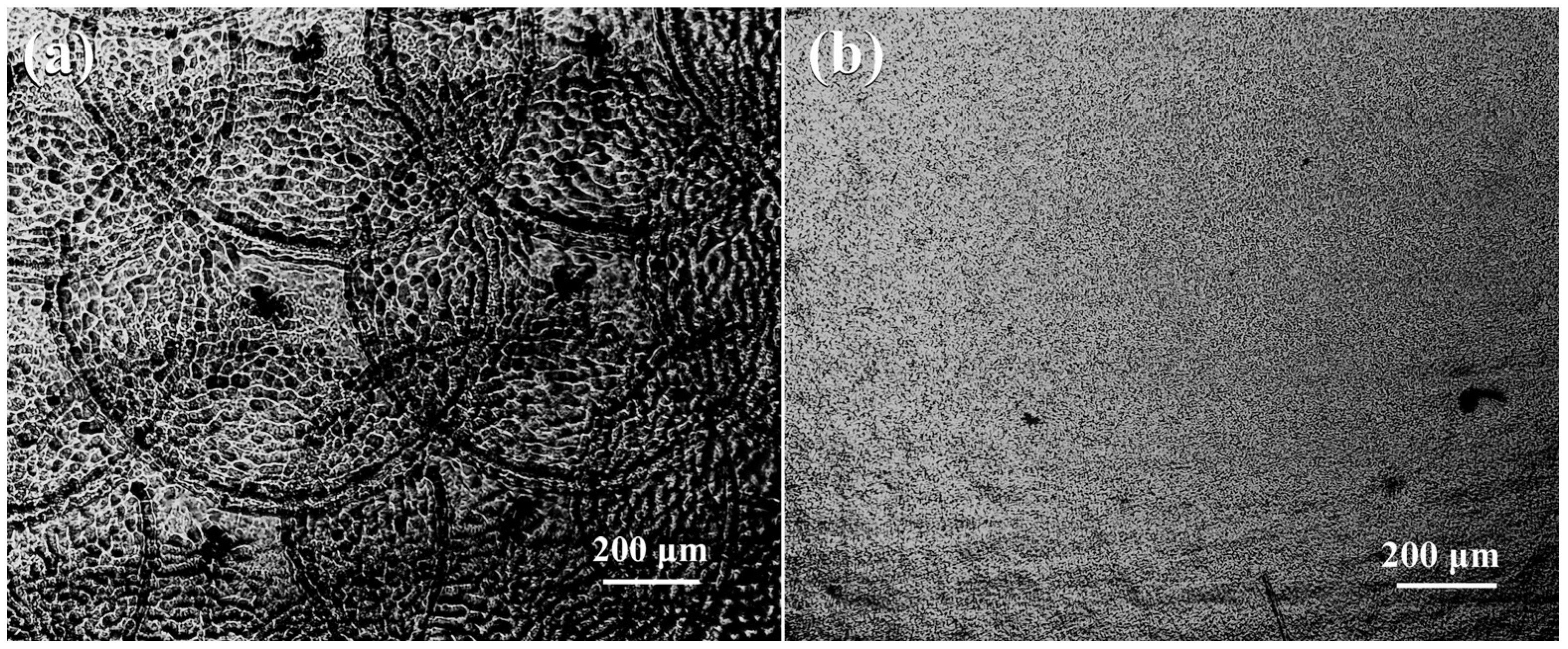
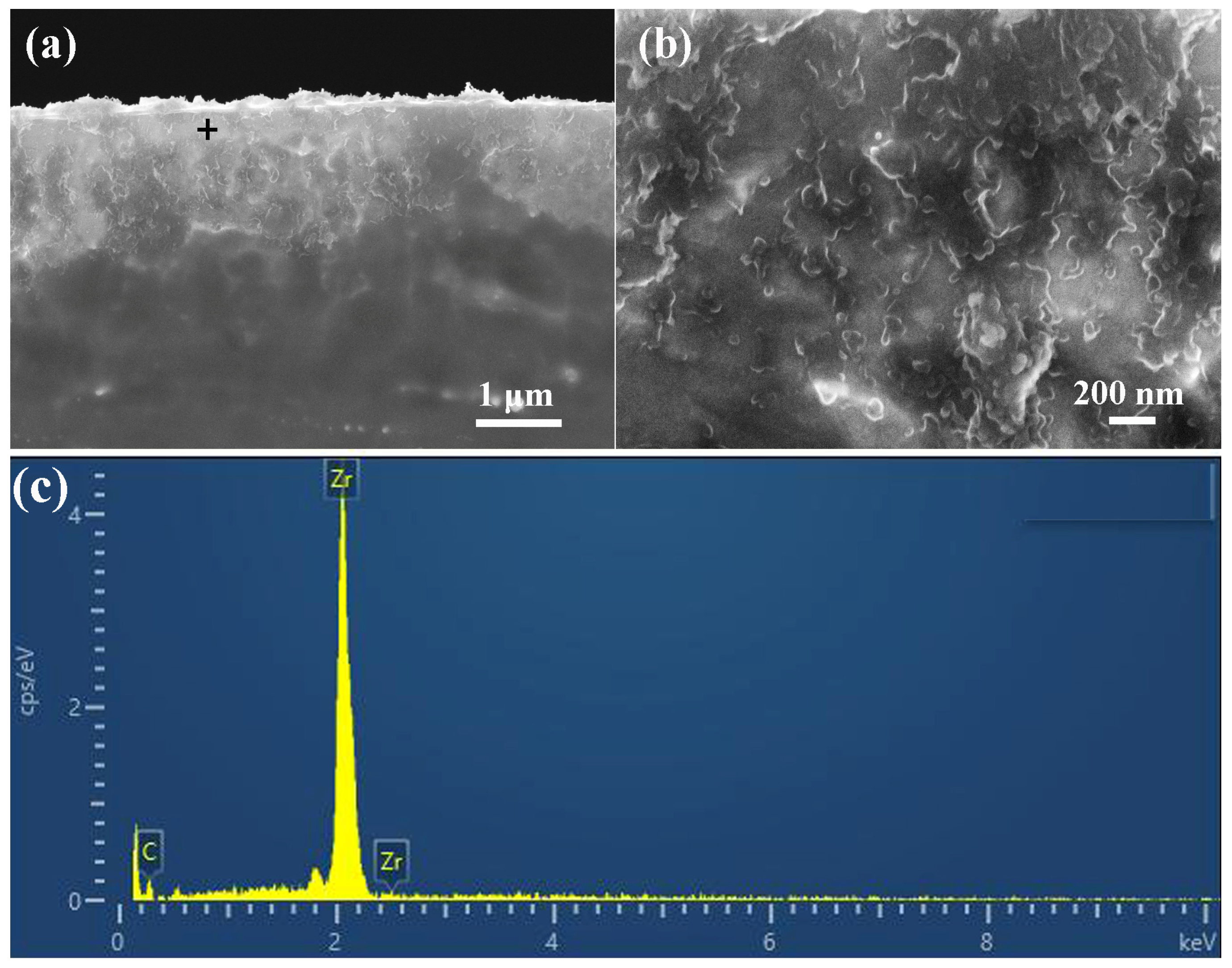
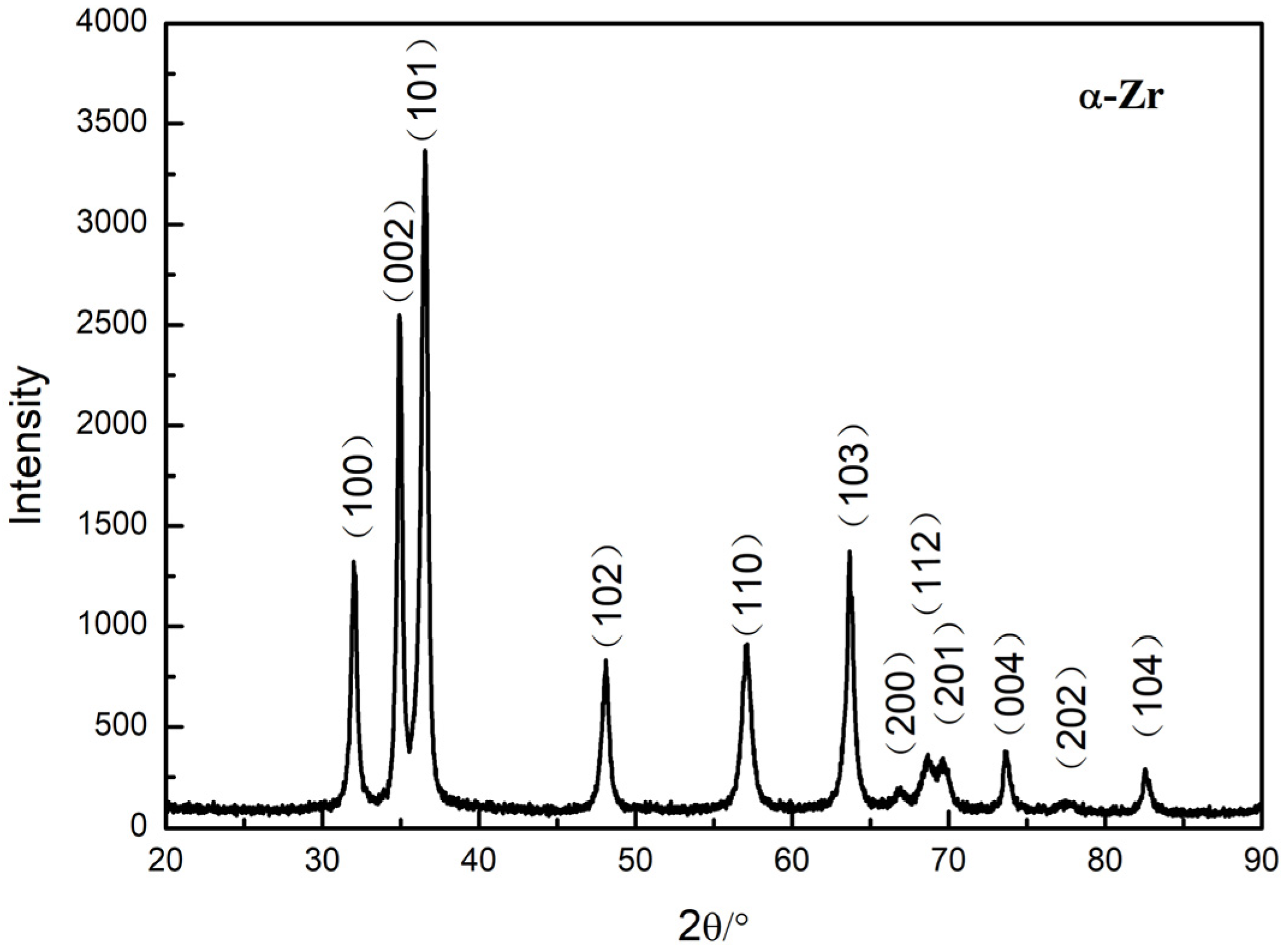
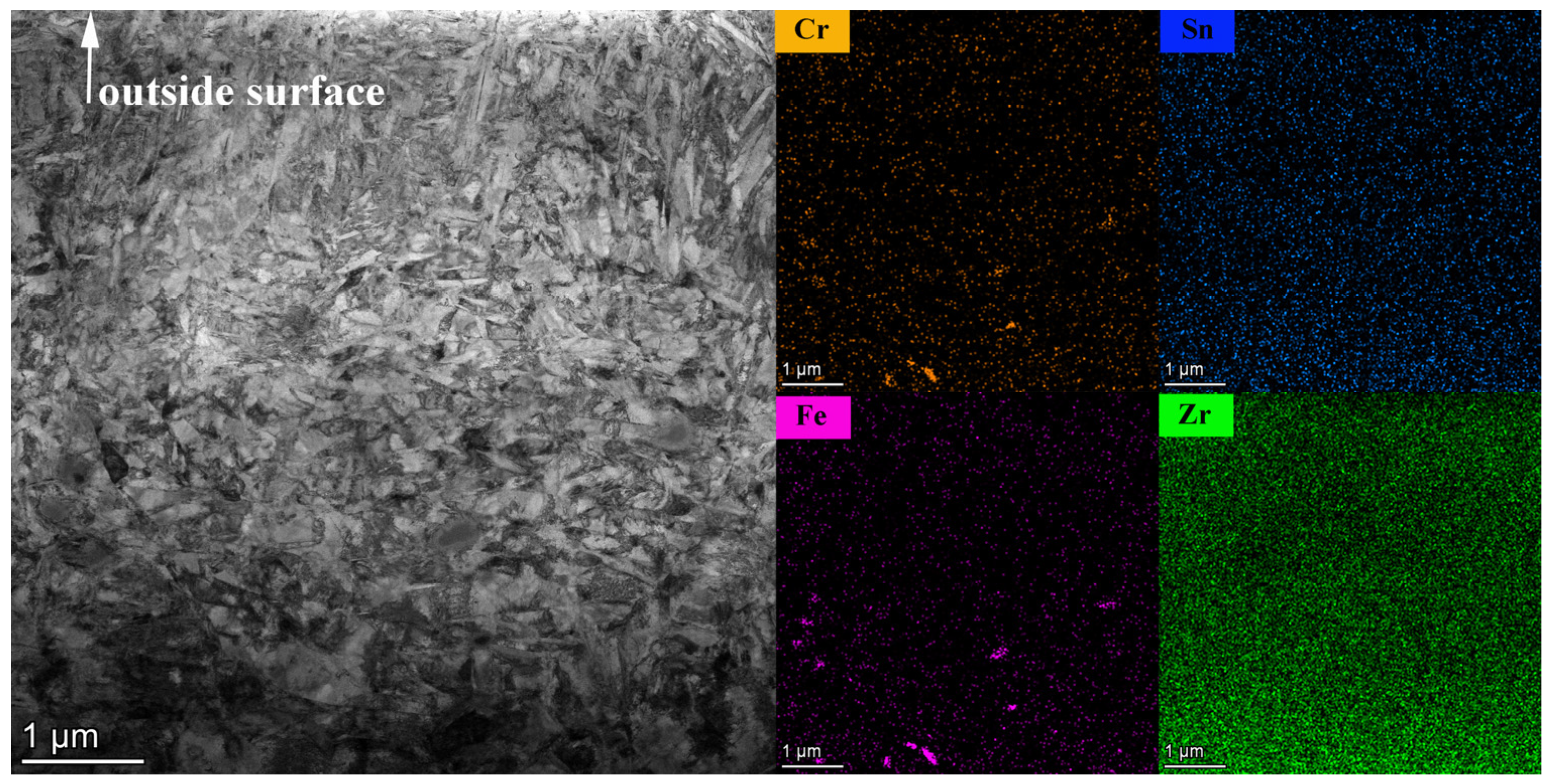
3.1. LST Layer Features

Figure 2 presents the surface morphologies of the LST and the NLST Zircaloy-4 specimens. In Figure 2, it is clearly shown that the morphologies of the LST and the NLST specimens are different. Figure 2a clearly shows that round spots with diameters of ~0.8 mm are distributed on the surface of the LST specimen, and the surface of this specimen is not flat. In contrast, the surface of the NLST specimen is flat, as shown in Figure 2b.
Figure 3 shows the cross-sectional morphology of the LST Zircaloy-4 specimen and a magnified image of the cross-sectional morphology of the LST specimen. As can be seen in Figure 3a, the morphology of the LST layer with a thickness of ~1.5 μm is different with the matrix. It is not flat and forms “cauliflower-like” undulations, as shown in Figure 3b. The X-ray spectroscopy (EDS) spectrum of the black cross-sectional area indicated in Figure 3a is shown in Figure 3c: it is clearly shown that there is no O peak in this spectrum. This means that no Zr was oxidized during the whole LST process.
Figure 4 shows the XRD diffraction pattern of the LST Zircaloy-4 specimen. As can be seen in Figure 4, only the α-Zr phase was identified in the LST Zircaloy-4 specimen. This indicates that LST cannot change the phase of the specimen. These peaks are consistent with those of the PDF97-065-3529 card for α-Zr and have no shift. It means there is no residual stress distributed in the LST layer. In Figure 1, we can also see that there are no diffraction peaks of ZrO2 and ZrHx. It is shown that the specimen was not oxidized and absorbed H during the entire LST process.
Figure 5 presents the TEM image of the cross-sectional morphology of the LST Zicaloy-4 specimen and the distributions of elements in the cross-sectional LST layer. It is clearly shown that there are Zr sub-grains formed in the LST layer. And from the Cr and Fe mapping images, we can see that no Fe-Cr precipitations are distributed in the upper part of the LST layer. This indicates that these Fe-Cr precipitations are dissolved into the matrix in the LST layer.

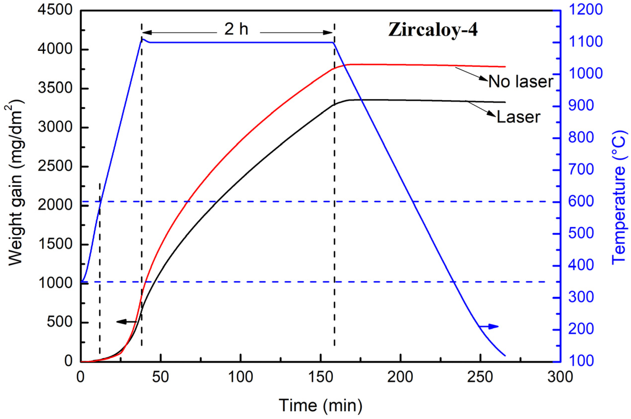
3.2. Weight Gain Curve

Figure 6 shows the weight gain vs. the exposure time for the LST and the NLST Zircaloy-4 specimens corroded in steam at 1100 °C for 2 h. In our test, data collection started at 350 °C. In this figure, the difference in the weight gains between the LST and NLST Zircaloy-4 specimens is obvious when increasing the corrosion time. In this figure, we can know that the weight gain of the LST Zircaloy-4 specimen is less than that of the NLST Zircaloy-4 specimen after corroding for the same time. The weight gain is greater, and the corrosion rate is faster. This means that the corrosion resistance of the LST Zircaloy-4 specimen is better than that of the NLST Zircaloy-4 specimen. So, we can conclude that LST can enhance the corrosion resistance of Zircaloy-4 corroded in steam at 1100 °C.

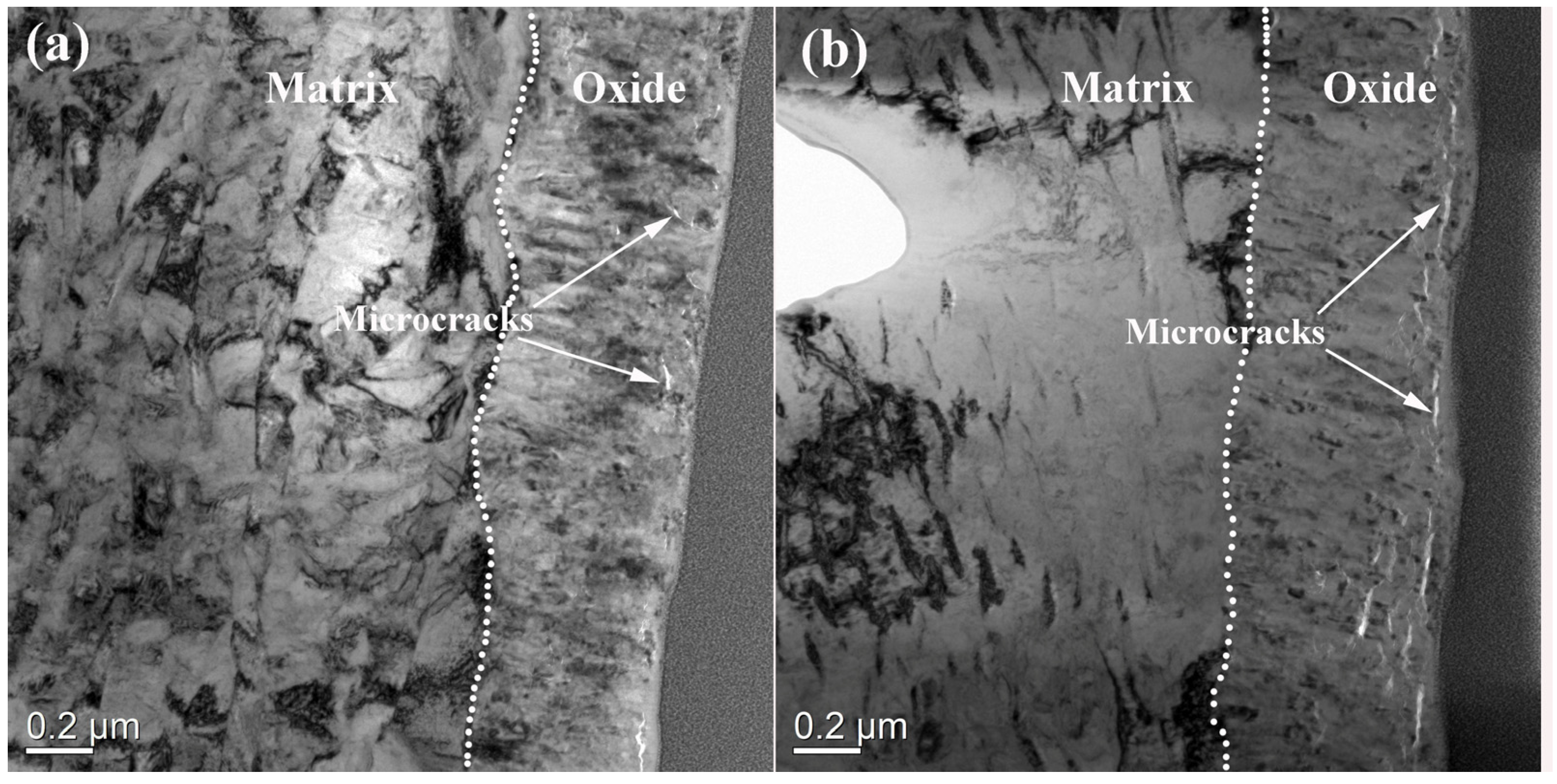
3.3. Oxide Film Morphologies

Figure 7 shows the bright-field images of the cross-sectional oxide films of the LST and NLST Zircaloy-4 specimens after corroding in steam at 600 °C for 0 min. Both thicknesses of these two oxide films are ~600 nm. In Figure 5, it can be seen that this corrosion is in the pre-transition stage. Figure 7a shows the morphology of the cross-sectional morphology of the oxide film formed on the surface of the LST Zricaloy-4 specimen. It is shown that some microcracks distribute in the oxide film, and the matrix grains are sub-grains. It means that the Zr sub-grains in the LST layer were not completely consumed during the corroding process. This oxide film resulted from the LST layer. However, more of microcarcks appear in the oxide film of the NLST Zircaloy-4 specimen, as shown in Figure 7b. And the matrix grain is fully recrystallized. It is indicted that the LST layer can affect the oxide film morphology. In other words, LST can restrain microcrack formation in the oxide film. The reason for this phenomenon will be illustrated in the next part of this paper.
Figure 8 shows the fracture surface morphologies of oxide films formed on the surface of the LST and NLST Zircaloy-4 specimens corroded in steam at 1100 °C for 0 min. In Figure 5, it can be seen that the corrosion is in the post-transition stage. Figure 8a,c show the images of the fracture surface morphologies of oxide film on the LST Zircaloy-4 specimen. Figure 8b,d show the images of the fracture surface morphologies of oxide film on the NLST Zircaloy-4 specimen. Comparing Figure 8a with Figure 8b, it can be seen that the thicknesses of the oxide films formed on the surfaces of the LST and the NLST Zircaloy-4 specimens are almost the same at ~28 μm. Figure 8c shows a magnified image of the local oxide in Figure 8a. It clearly shows that there are nearly no defects distributed in the oxide film. Figure 8d shows a magnified image of the local oxide. It can be seen that there are many defects distributed in the oxide such as microcracks and micropores. Comparing Figure 8c with Figure 8d, it can be seen that there is an obvious difference between the oxide film formed on the surface of the LST Zircaloy-4 specimen and that of the NLST Zircaloy-4 specimen.
Figure 9 presents the normal XRD patterns of the oxide film formed on the surfaces of the LST and NLST Zircaloy-4 specimens corroded in steam at 1100 °C for 0 min. It is worth noting that the t-(101) Bragg peak intensity of the oxide film on the surface of the LST Zicaloy-4 specimen is stronger than that of the NLST Zircaloy-4 specimen. In addition, the total integrated intensities I(hkl) of the m-(−111), m-(111) and t-(101) were used to determine the t-ZrO2 volume fraction fT with respect to the total volume of zirconia using the Garvie–Nicholson formula [38].
f T = I T ( 101 ) I T ( 101 ) + I M ( 111 ) + I M ( 111 )
Here, the peak area and the peak height are treated as diffraction peak intensities to calculate fT. And then, the average value of the fT calculated using peak area and the peak height as diffraction peak intensities is considered to be the real fT. After calculating, the fT of the LST Zircaloy-4 specimen is ~12.8%, and the fT of the NLST Zircaloy-4 specimen is ~6.8%. It is clearly indicated that the volume fraction of t-ZrO2 in the oxide film formed on the surface of the LST Zircaloy-4 specimen is higher than that of the NLST Zircaloy-4 specimen after corroding in steam at 1100 °C for 0 min.

4. Discussion

Generally speaking, the corrosion processes of Zirconium alloys can be divided into pre-transition and post-transition stages. In the pre-transition stage, the oxide film is dense and has a protective effect, but in the post-transition stage, the oxide film lost protection effect and the corrosion rate obviously increased [39,40,41]. Therefore, the corrosion rate is determined by the properties of the oxide film. It is well known that when the thickness of the oxide films of the zirconium alloys exceeds a critical value 2–3 μm during the corrosion process, it corresponds to an increase in the oxidation rate [42,43,44]. So, the properties of the oxide film formed in the earlier stage will affect the corrosion behavior of the later corrosion stage. In Figure 6, we can see that the LST and the NLST Zircaloy-4 specimens corroding in the steam at 600 °C are in the pre-transition stage. And in Figure 7, it is clearly shown that more of microcracks appear in the oxide film of the NLST Zircaloy-4 specimen than that of the LST Zircaloy-4 specimen. In Figure 8, we can also see that the oxide film formed on the surface of the LST Zircaloy-4 specimen is denser than that of the NLST Zircaloy-4 specimen. Moreover, there are nearly no defects distributed in the oxide film of the LST Zircaloy-4 specimen, But, microcracks and micropores are clearly shown in the oxide film of the NLST Zircaloy-4 specimen. In Figure 5, we can see that the Fe-Cr precipitates are dissolved and disappear in the LST layer. It is well known that the oxidation rates of the precipitates in zirconium alloys are generally slower than those of α-Zr [45,46,47,48]. Therefore, the precipitates are incorporated into the oxide film. And then, these precipitated can be full oxidized in the oxide film at last. The Pilling Bedworth ratio (P.B. ratio) of Fe is 1.77, and that of Cr is 2.02; they are both larger than that of Zr: 1.56 [49]. After the precipitated oxidization, local additional stress in the oxide film will be generated, and the t→m transformation can be initiated [50]. And then, this process can result in microcracks formation. The illustration of the microcracks’ formation, which resulted from precipitates in the oxide film, was shown in detail in a work published by Huang et al. [51]. These cracks will cause the oxide film to lose its protective effect and then increase the corrosion rate. Therefore, the corrosion resistance of the NLST Zircaloy-4 specimen is worse than that of the LST Zircaloy-4 specimen, as shown in Figure 6.
On the other hand, during the corrosion of zirconium alloys, t-m transformation could cause microcrack formation and oxide film damage due to the volumetric expansion of ~5% [52,53]. Since some elements have a valence of +2 or +3, they could be added to stabilize commercial t-ZrO2 ceramics [54,55,56]. So, Fe and Cr could be the elements for stabilizing the t-ZrO2 phase since they can introduce many intrinsic oxygen vacancies [57,58]. In Figure 5, nearly no Fe-Cr precipitates appear in the LST layer; this means that the solid solution of Fe and Cr in α-Zr is higher than that in the common matrix. And then, these solid solutions of Fe and Cr in α-Zr could stabilize the t-ZrO2 phase. Therefore, more t-ZrO2 could be distributed in the oxide film formed on the surface of the LST Zircaloy-4 specimen than that of the NLST Zircaloy-4 specimen. This is consistent with our XRD result, as shown in Figure 9. The volume fraction of t-ZrO2 is higher, so the number of microcrack that resulted from t-m transformation could be less. This is consistent with the result shown in Figure 7. Consequently, the corrosion resistance of the LST Zircaloy-4 specimen could be better than that of the NLST Zircaloy-4 specimen, as shown in Figure 6. It is concluded that the solid solutions of Fe and Cr in α-Zr are higher, so the corrosion resistance of the LST Zircaloy-4 specimen is better.

5. Conclusions

LST was conducted on the Zircaloy-4 plate specimen, the LST layer of the specimen was also the α-Zr phase, no oxidation was observed, no ZrHx formation was noted, and the Fe-Cr precipitates were dissolved in the Zr matrix. The corrosion resistance of the LST Zircaloy-4 specimen was better than that of the NLST Zircaloy-4 specimen. The main reason could be attributed to the higher solid solutions of Fe and Cr and there being fewer Fe-Cr precipitates in the LST layer. This work was an attempt to study the surface treatment technology rather than the coating technology for the development of ATF cladding. It could be necessary to carry out a systematic study of the corrosion resistances of the different kinds of zirconium alloys corroded in high-temperature steam after conducting tests using the different laser parameters in future. This technology may be an option for the development of ATF cladding.

Author Contributions

Conceptualization, S.X. and R.M.; Methodology, R.M.; Validation, T.S.; Formal analysis, T.S., Y.Y., J.L., Y.G. and J.Q.; Investigation, S.X., T.S., Y.Y., J.L. and Y.G.; Resources, Y.G.; Data curation, Y.Y., J.L. and Y.G.; Writing—original draft, S.X. and W.L.; Writing—review & editing, S.X. and W.L.; Visualization, J.Q. and W.L.; Supervision, R.M., W.L. and D.Y.; Project administration, J.Q. and D.Y.; Funding acquisition, S.X. and D.Y. All authors have read and agreed to the published version of the manuscript.

Funding

This research was funder by the National Natural Science Foundation of China (12375272).

Institutional Review Board Statement

Not applicable.

Informed Consent Statement

Not applicable.

Data Availability Statement

The original contributions presented in the study are included in the article, further inquiries can be directed to the corresponding author.

Acknowledgments

We thank Xiaochun Liu at Changsha University of Science and Technology for his assistance with TEM analysis.

Conflicts of Interest

The authors declare no conflict of interest.

References

  1. Zinkle, S.J.; Terrani, K.A.; Gehin, J.C.; Ott, L.J.; Snead, L.L. Accident tolerant fuels for LWRs: A perspective. J. Nucl. Mater. 2014, 448, 374–379. [Google Scholar] [CrossRef]
  2. Ott, L.J.; Robb, K.R.; Wang, D. Preliminary assessment of accident-tolerant fuels on LWR performance during normal operation and under DB and BDB accident conditions. J. Nucl. Mater. 2014, 448, 520–533. [Google Scholar] [CrossRef]
  3. Koo, Y.-H.; Yang, J.-H.; Park, J.-Y.; Kim, K.-S.; Kim, H.-G.; Kim, D.-J.; Jung, Y.-I.; Song, K.-W. KAERIs development of LWR accident tolerant fuel. Nucl. Technol. 2014, 186, 295–304. [Google Scholar] [CrossRef]
  4. Wei, K.; Cui, L.; Li, B.; Yang, Z.; Han, Y.; Kano, S.; Abe, H. Direct experimental evidence of the reduction of Cr2O3 by Zr at high temperature. Corros. Sci. 2023, 225, 111587. [Google Scholar] [CrossRef]
  5. Huang, J.; Zou, S.; Xiao, W.; Yang, C.; Yu, H.; Zhang, L.; Zhang, K. Microstructural evolution of Cr-coated Zircaloy-4 alloy prepared by multi-arc plating during high temperature oxidation. J. Nucl. Mater. 2022, 562, 153616. [Google Scholar] [CrossRef]
  6. Ševeček, M.; Gurgen, A.; Seshadri, A.; Che, Y.; Wagih, M.; Phillips, B.; Champagne, V.; Shirvan, K. Development of Cr cold spray-coated fuel cladding with enhanced accident tolerance. Nucl. Eng. Technol. 2018, 50, 229–236. [Google Scholar] [CrossRef]
  7. Yang, J.; Steinbrück, M.; Tang, C.C.; Grobe, M.; Liu, J.; Zhang, J.; Yin, D.; Wang, S.Z. Review on chromium coated zirconium alloy accident tolerant fuel cladding. J. Alloys Compd. 2022, 895, 162450. [Google Scholar] [CrossRef]
  8. Xiang, Y.; Yang, H.; Chen, Q.; Peng, X.; Zhang, R.; Wei, T.; Liu, C.; Chen, H. Long-term high-temperature steam oxidation behavior of Cr-coated Zircaloy-4 alloy for accident tolerant fuel. Mater. Corros. 2022, 73, 2009–2018. [Google Scholar] [CrossRef]
  9. Han, X.; Xue, J.; Peng, S.; Zhang, H. An interesting oxidation phenomenon of Cr coatings on Zry-4 substrates in high temperature steam environment. Corros. Sci. 2019, 156, 117–124. [Google Scholar] [CrossRef]
  10. Xu, C.; Wang, X.; Zhou, Q.; Xue, W.; Jin, X.; Du, J.; Li, Y.; Li, S. TEM characterizations of a ZrO2/Cr composite coating on Zr-1Nb alloy after 1200 °C steam oxidation. Mater. Charact. 2023, 197, 112701. [Google Scholar] [CrossRef]
  11. Liao, H.; Huang, W.; Ruan, H.; Zhang, T.; Ning, Y.; Zhu, P.; Xu, X.; Xu, M.; Yin, S.; Su, Y.; et al. Oxidation behavior and microstructural evolution of Cr coatings prepared by multi-arc ion plating on Zry-4 in steam environments up to 1400 °C. J. Nucl. Mater. 2023, 583, 154530. [Google Scholar] [CrossRef]
  12. Meng, C.; Ma, J.; Wang, H.; Liu, W.; Hu, Y.; Zhang, B.; Tu, M.; Yuan, C.; He, X. Enhancing the oxidation behaviors of Zr alloys for nuclear fuel cladding using nanolamerllar Cr/CrN coating. Corros. Sci. 2024, 227, 111725. [Google Scholar] [CrossRef]
  13. Li, Q.; Song, P.; Zhang, R.; Li, Z.; Li, Z.; Wang, Y.; Du, P.; Lu, J. Oxidation behavior and Cr-Zr diffusion of Cr coating prepared by atmospheric plasma spraying on Zircaloy-4 cladding in steam at 1300 °C. Corros. Sci. 2022, 203, 110378. [Google Scholar] [CrossRef]
  14. Kim, H.; Kim, I.; Jung, Y.; Park, D.; Park, J.; Koo, Y. Adhesion property and high temperature oxidation behavior of Cr-coated Zircaloy-4 cladding tube prepared by 3D laser coating. J. Nucl. Mater. 2015, 465, 531–539. [Google Scholar] [CrossRef]
  15. Han, X.; Chen, C.; Tan, Y.; Feng, W.; Peng, S.; Zhang, H. A systematic study of the oxidation behavior of Cr coatings on Zry4 substrates in high temperature steam environment. Corros. Sci. 2020, 174, 108826. [Google Scholar] [CrossRef]
  16. Brachet, J.-C.; Rouesne, E.; Ribis, J.; Guilbert, T.; Urvoy, S.; Nony, G.; Toffolon-Masclet, C.; Le Saux, M.; Chaabane, N.; Palancher, H.; et al. High temperature steam oxidation of chromium-coated zirconium based alloys: Kinetics and process. Corros. Sci. 2020, 167, 108537. [Google Scholar] [CrossRef]
  17. Liu, H.; Feng, Y.; Yao, Y.; Li, B.; Wang, R.; Shi, X.; Li, P.; Shu, J.; Huang, F.; Huang, Q.; et al. Effect of the 345 °C and 16.5 MPa autoclave corrosion on the oxidation behavior of Cr-coated zirconium claddings in the high-temperature steam. Corros. Sci. 2021, 189, 109608. [Google Scholar] [CrossRef]
  18. Wang, D.; Zhong, R.; Zhang, Y.; Chen, P.; Lan, Y.; Yu, J.; Su, G.H.; Qiu, S.; Tian, W. Isothermal experiments on steam oxidation of magnetron-sputtered chromiumcoated zirconium alloy cladding at 1200 °C. Corros. Sci. 2022, 206, 110544. [Google Scholar] [CrossRef]
  19. Liu, J.; Cui, Z.; Hao, Z.; Ma, D.; Lu, J.; Cui, Y.; Li, C.; Liu, W.; Xie, S.; Hu, P.; et al. Steam oxidation of Cr-coated Sn-containing Zircaloy solid rod at 1000 °C. Corros. Sci. 2021, 190, 109682. [Google Scholar] [CrossRef]
  20. Liu, J.; Steinbrück, M.; Große, M.; Stegmaier, U.; Tang, C.; Yun, D.; Yang, J.; Cui, Y.; Seifert, H.J. Systematic investigations on the coating degradation mechanism during the steam oxidation of Cr-coated Zry-4 at 1200 °C. Corros. Sci. 2022, 202, 110310. [Google Scholar] [CrossRef]
  21. Wei, T.; Zhang, R.; Yang, H.; Liu, H.; Qiu, S.; Wang, Y.; Du, P.; He, K.; Hu, X.; Dong, C. Microstructure, corrosion resistance and oxidation behavior of Cr-coatings on Zircaloy-4 prepared by vacuum arc plasma deposition. Corros. Sci. 2019, 158, 108077. [Google Scholar] [CrossRef]
  22. Xie, S.J.; Liu, K.Q.; Meng, R.Z.; Cui, Y.G.; Wang, C.; Lu, J.Q.; Song, Z.X.; Wang, D.W.; Liu, W.B.; Qiu, J.; et al. Formation of intragranular nanocavities in the Cr2O3 layer during the corrosion of Cr3C2+Cr coated ZirloTM. Corror. Sci. 2024, 233, 112117. [Google Scholar] [CrossRef]
  23. Yeom, H.; Maier, B.; Johnson, G.; Dabney, T.; Lenling, M.; Sridharan, K. High temperature oxidation and microstructural evolution of cold spray chromium coatings on Zircaloy-4 in steam environments. J. Nucl. Mater. 2019, 526, 151737. [Google Scholar] [CrossRef]
  24. Yang, J.; Stegmaier, U.; Tang, C.; Steinbrück, M.; Große, M.; Wang, S.; Seifert, H.J. High temperature Cr-Zr interaction of two types of Cr-coated Zr alloys in inert gas environment. J. Nucl. Mater. 2021, 547, 152806. [Google Scholar] [CrossRef]
  25. Pysarenko, V.; Kuznetsova, T.; Samelyuk, A. Structure and mechanical properties of ZrCr2 intermetallic compound within the temperature range 20–1300 °C. Mater. Sci. 2004, 40, 83–88. [Google Scholar] [CrossRef]
  26. Zhang, L.; Lai, P.; Liu, Q.; Zeng, Q.; Lu, J.; Guo, X. Fretting wear behavior of zirconium alloy in B-Li water at 300 °C. J. Nucl. Mater. 2018, 499, 401–409. [Google Scholar] [CrossRef]
  27. Jiang, J.; Ma, X.; Wang, B. Positive or negative role of preoxidation in the crack arresting of Cr coating for accident tolerant fuel cladding. Corros. Sci. 2021, 193, 109870. [Google Scholar] [CrossRef]
  28. Kim, D.; Steinbrück, M.; Grosse, M.; Tang, C.; Lee, Y. Eutectic reaction and oxidation behavior of Cr-coated Zircaloy-4 accident-tolerant fuel cladding under various heating rates. J. Nucl. Mater. 2023, 583, 154538. [Google Scholar] [CrossRef]
  29. Zhao, Y.L.; Liu, J.Z. The effect of laser surface treatment on the nodular corrosion of Zircaloy-4. Rare Metal. Mat. Eng. 1996, 25, 44–46. [Google Scholar]
  30. Yang, J.X.; Wang, X.; Wen, Q.; Wang, X.B.; Wang, R.S.; Zhang, Y.W.; Xue, W.B. The effect of microarc oxidation and excimer laser processing on the microstructure and corrosion resistance of Zr-1Nb alloy. J. Nucl. Mater. 2015, 467, 186–193. [Google Scholar] [CrossRef]
  31. Andersson, T.; Thorvaldsson, T.; Wilson, A.; Wardle, A.M. Improvement in Water Reactor Fuel Technology and Utilization; IAEA: Vienna, Austria, 1987; pp. 435–449. [Google Scholar]
  32. Lee, S.J.; Park, C.J.; Lim, Y.S.; Kwon, H.S. Influences of laser surface alloying with niobium on the corrosion resistance of Zircaloy-4. J. Nucl. Mater. 2003, 321, 177–183. [Google Scholar] [CrossRef]
  33. Chai, L.J.; Wu, H.; Wang, S.Y.; Chen, K.; Wang, T.T.; Xia, J.Y. Characterization of microstructure and hardness of a Zr-2.5 Nb alloy surface-treated by pulsed laser. Mater. Chem. Phys. 2017, 198, 303–309. [Google Scholar] [CrossRef]
  34. Chai, L.J.; Chen, K.; Zhi, Y.; Murty, K.L.; Chen, L.Y.; Yang, Z.N. Nanotwins induced by pulsed laser and their hardening effect in a Zr alloy. J. Alloys Compd. 2018, 748, 163–170. [Google Scholar] [CrossRef]
  35. Tang, C.; Zhu, W.-H.; Ma, J.-G.; Ma, Y.; Zhu, H.-M.; Wang, X.-L.; Chen, Z.-Y. Microstructure and properties of composite ceramic coating on Zr-4 alloy surface by laser cladding, Zircaloy. Equip. Manuf. Technol. 2016, 1, 29–31. [Google Scholar]
  36. Wu, H.; Fan, H.-Y.; Ying, S.-H.; Huang, X.-Q. Investigation of laser surface alloying with niobium on the depth and the structure of Zircaloy-4. Eng. Mater. 2005, 8, 50–52. [Google Scholar]
  37. Liu, Y.Y.; Yang, Y.L.; Dong, D.Y.; Wang, J.; Zhou, L.L. Improving wear resistance of Zr-2.5 Nb alloy by formation of microtextured nitride layer produced via laser surface texturing/plasma nitriding technology. Surf. Interfaces 2020, 20, 100638. [Google Scholar] [CrossRef]
  38. Zhang, H.X.; Fruchart, D.; Hlil, E.K.; Ortega, L.; Li, Z.K.; Zhang, J.J.; Sun, J.; Zhou, L. Crystal structure, corrosion kinetics of new zirconium alloys and residual stress analysis of oxide films. J. Nucl. Mater. 2010, 396, 65–70. [Google Scholar] [CrossRef]
  39. Grandjean, A.; Serruys, Y. Metal and oxygen mobilities during Zircaloy-4 oxidation at high temperature. J. Nucl. Mater. 1999, 273, 111–115. [Google Scholar] [CrossRef]
  40. Müller, S.; Lanzani, L. Corrosion of Zr-1Nb and Zr-2.5Nb in 0.1 M LiOH at 343 °C. Procedia Mater. Sci. 2015, 8, 46–55. [Google Scholar] [CrossRef]
  41. Cox, B. Some thoughts on the mechanisms of in-reactor corrosion of zirconium alloys. J. Nucl. Mater. 2005, 336, 331–368. [Google Scholar] [CrossRef]
  42. Dawson, J.K.; Long, G.; Seddon, W.E.; White, J.F. The kinetics and mechanism of the oxidation of zricaloy-2 at 350–500 °C. J. Nucl. Mater. 1968, 25, 179–200. [Google Scholar] [CrossRef]
  43. Cox, B. Pore structure in oxide films on irradiated and unirradiated zirconium alloys. J. Nucl. Mater. 1987, 148, 332–343. [Google Scholar] [CrossRef]
  44. Liao, J.J.; Yang, Z.; Qiu, S.; Peng, Q.; Li, Z.; Zhang, J. The correlation between tetragonal phase and the undulated metal/oxide interface in the oxide films of zirconium alloys. J. Nucl. Mater. 2019, 524, 101–110. [Google Scholar] [CrossRef]
  45. Zhong, X.Y.; Yang, B.; Li, M.C.; Yao, M.Y.; Zhou, B.X. EIS characterization of the oxide film on Zr-4 alloy surface in super-heated steam. Rare Metal Mater. Eng. 2010, 39, 2155–2168. (In Chinese) [Google Scholar]
  46. Weidinger, H.G.; Ruhmann, H.; Cheliotis, G.; Maguire, M.; Yau, T.L. Corrosion-electrochemical properties of zirconium intermetallics. In 9th International Symposium on Zirconium in the Nuclear Industry; ASTM STP 1132; ASTM International: West Conshohocken, PA, USA, 1991; pp. 499–535. [Google Scholar]
  47. Proff, C.; Abolhassani, S.; Lemaignan, C. Oxidation behavior of binary zirconium alloys containing intermetallic precipitates. J. Nucl. Mater. 2011, 416, 125–134. [Google Scholar] [CrossRef]
  48. Proff, S.; Abolhassani, S.; Lemaignan, C. Oxidation behaviour of zirconium alloys and their precipitates—A mechanistic study. J. Nucl. Mater. 2013, 432, 222–238. [Google Scholar] [CrossRef]
  49. Baek, J.H.; Jeong, Y.H.N.; Kim, I.S. Effects of the accumulated annealing parameter on the corrosion characteristics of a Zr-0.5Nb-1.0Sn-0.5Fe-0.25Cr alloy. J. Nucl. Mater. 2000, 280, 235–245. [Google Scholar] [CrossRef]
  50. Baek, J.H.; Jeong, Y.H. Depletion of Fe and Cr within precipitates during Zircaloy-4 oxidation. J. Nucl. Mater. 2002, 304, 107–116. [Google Scholar] [CrossRef]
  51. Huang, J.; Yao, M.-Y.; Gao, C.-Y.; Liang, X.; Peng, J.C.; Zhang, J.-L.; Zhou, B.-X. The influence of second phase particles on the crack formation in oxide films formed on zirconium alloys. Corros. Sci. 2015, 99, 172–177. [Google Scholar] [CrossRef]
  52. Preuss, M.; Frankel, P.; Polatidis, E.; Wei, J.; Smith, J.; English, C.; Wang, F.; Cottis, B.; Lyon, S.; Lozano-Perez, S.; et al. Studies regarding corrosion mechanisms in zirconium alloys. In Proceedings of the International Symposium on Zirconium in the Nuclear Industry, Chengdu, China, 9–13 May 2010; p. 649. [Google Scholar]
  53. Bouvier, P.; Godlewski, J.; Lucazeau, G. A Raman study of the nanocrystallite size effect on the pressure-temperature phase diagram of zirconia grown by zirconium-based alloys oxidation. J. Nucl. Mater. 2002, 300, 118–126. [Google Scholar] [CrossRef]
  54. Yasuda, K.; Arai, S.; Itoh, M.; Wada, K. Influence of Y2O3 distribution on the rate of tetragonal to monoclinic phase transformation of yttria-stabilized zirconia during hydrothermal aging. J. Mater. Sci. 1999, 34, 3597–3604. [Google Scholar] [CrossRef]
  55. Sankar, U.; Satgunam, M.; Amiriyan, M.; Singh, R.; Teng, W.D. Sintering and densification behavior of Zno-doped Y-TZP ceramics. Appl. Mech. Mater. 2011, 83, 197–203. [Google Scholar] [CrossRef]
  56. Ramesh, S.; Meenaloshini, S.; Tan, C.Y.; Chew, W.J.K.; Teng, W.D. Effect of manganese oxide on the sintered properties and low temperature degradation of Y-TZP ceramics. Ceram. Int. 2008, 34, 1603–1608. [Google Scholar] [CrossRef]
  57. Hulme, H.; Baxter, F.; Babu, R.P.; Denecke, M.A.; Gass, M.; Steuwer, A.; Norén, K.; Carlson, S.; Preuss, M. An X-ray absorption near-edge structure (XANES) study of the Sn L3 edge in zirconium alloy oxide films formed during autoclave corrosion. Corros. Sci. 2016, 105, 202–208. [Google Scholar] [CrossRef]
  58. Froideval, A.; Degueldre, C.; Segre, C.U.; Pouchon, M.A.; Grolimund, D. Niobium speciation at the metal/oxide interface of corroded niobium-doped Zircaloys: A X-ray absorption near-edge structure study. Corros. Sci. 2008, 50, 1313–1320. [Google Scholar] [CrossRef]
Figure 1. A schematic diagram of the LST process for the Zircaloy-4 specimen.
Applsci 14 04977 g001
Figure 2. The surface morphologies of the LST (a) and NLST (b) Zircaloy-4 specimens.
Applsci 14 04977 g002
Figure 3. The cross-sectional morphology of the LST Zircaloy-4 (a), magnified image of the cross-sectional morphology of the LST Zircaloy-4 (b), and EDS spectrum of the black cross-sectional area (c).
Applsci 14 04977 g003
Figure 4. X-ray diffraction pattern of Zircaloy-4 after LST.
Applsci 14 04977 g004
Figure 5. The TEM image of the cross-sectional LST layer of Zircaloy-4 and the Cr, Sn, Fe, and Zr mapping images of the LST layer.
Applsci 14 04977 g005
Figure 6. Weight gain vs. exposure time for the LST and NLST Zircaloy-4 specimens corroded in steam at 1100 °C for 2 h (the left arrow indicate the left Y-axis, the right arrow indicate the right Y-axis).
Applsci 14 04977 g006
Figure 7. Bright-field images of the cross-sectional oxide films of the LST (a) and NLST (b) Zircaloy-4 specimens after corroding in steam at 600 °C for 0 min.
Applsci 14 04977 g007
Figure 8. The fracture surface morphologies of the oxide films formed on the surfaces of the LST (a,c) and NLST (b,d) Zircaloy-4 specimens after corroding in steam at 1100 °C for 0 min.
Applsci 14 04977 g008
Figure 9. X-ray diffraction patterns of the oxide films formed on surfaces of the LST and NLST Zircaloy-4 specimens after corroding in steam at 1100 °C for 0 min.
Applsci 14 04977 g009
Disclaimer/Publisher’s Note: The statements, opinions and data contained in all publications are solely those of the individual author(s) and contributor(s) and not of MDPI and/or the editor(s). MDPI and/or the editor(s) disclaim responsibility for any injury to people or property resulting from any ideas, methods, instructions or products referred to in the content.

