Article

Magnetoelectric Nanoparticles for Wireless Peripheral Nerve Stimulation: A Computational Study

1
Dipartimento di Elettronica, Informazione e Bioingegneria (DEIB), Politecnico di Milano, 20133 Milan, Italy
2
Istituto di Elettronica e di Ingegneria dell’Informazione e delle Telecomunicazioni, Consiglio Nazionale delle Ricerche (CNR-IEIIT), 20133 Milan, Italy
*
Author to whom correspondence should be addressed.
Appl. Sci. 2024, 14(13), 5372; https://doi.org/10.3390/app14135372
Submission received: 28 May 2024 / Revised: 14 June 2024 / Accepted: 18 June 2024 / Published: 21 June 2024
(This article belongs to the Special Issue Electromagnetic Fields (EMF) Applications in Medicine)

Abstract

:
This study aims to precisely characterize the use of magnetoelectric nanoparticles (MENPs) for stimulating peripheral nerves. Numerical methods were employed to quantify the interaction between MENPs and nervous tissue. The influence of MENPs’ orientation, concentration and distance was assessed in terms of the external potential distribution exerted by the MENPs, the amplification of the exerted MENPs’ stimulation required to excite the neural fibers and the current injected into the intracellular space. The results highlight the significance of MENPs’ concentration for stimulation accuracy and efficiency, the impact of MENPs’ orientation on the electric potential distribution sensed by the nervous tissue, as well as the importance of the MENPs’ distance over the fibers’ recruitment. Given the considerable variability in the interaction between MENPs and nerves, our research provides a crucial step towards understanding this interaction, offering quantitative support for the application of MENPs in nervous tissue stimulation.

1. Introduction

Neuroprostheses are external devices integrated with neuromodulation which reinforce the input or output of a neural system, replacing or enhancing sensory, motor, and cognitive functions, aiming at improving the quality of life of impaired patients [1,2]. The technological development of recent years has moved towards the enhancement of the connection of such external devices to the human nervous systems to enable a safer, more effective and selective electrical stimulation.
As a part of our nervous system, peripheral nerves lie out from the brain and spinal cord and are characterized by different anatomical structures. They act as a conduit, bidirectionally exchanging information between different areas of the body and the central nervous system, communicating signals for both sensations and motor commands. Peripheral nerves are made of mixed nerve fibers: axons of motor or sensory fibers, surrounded by an insulating myelin called endoneurium, are bundled into groups named fascicles.
In the context of restoring the functions of the peripheral nervous system, there is a need for neural interfaces which are highly selective and minimal invasive, leading to an unavoidable trade-off between selectivity and invasiveness. Various technologies for neural interfaces have been researched for many years, such as extraneural, intrafascicular, penetrating, and regenerative interfaces. However, some limitations concern these solutions; to mention some, the stiffness of the penetrating electrodes, the difficulty of the implantation technique for the intrafascicular electrodes, and the low signal-to-noise ratio of the extraneural electrodes [3,4,5].
In this context, nanotechnology has emerged as a potential novel approach to enhance the coupling between external devices and the neuron system since the dimensions of nanoengineered materials could allow for a non-invasive and highly focal neuromodulation.
Particularly, magnetoelectric nanoparticles (MENPs) have demonstrated to be a cutting-edge technology to be used for single-neuron-level stimulation both at the central and peripheral sites [6,7,8,9]. Their unique innovative potential is due to the magnetoelectric (ME) effect, which consists of a coupling between the external applied magnetic field and the generated local electric field, and vice versa. The direct effect occurs when the ME material is placed inside an external magnetic field: the magnetostrictive phase experiences a non-zero strain which is mechanically transferred to the piezoelectric phase, and, in turn, it transduces the mechanical deformation into electrical charges. This property, specific of magnetoelectric composites and of multiferroic solids that simultaneously possess both the ferromagnetic and ferroelectric ordering, has also been recently verified at room temperature, allowing for their use in biomedical applications. The magnitude of the two phases’ interaction is defined by the ME coefficient αE = δE/δH [V/cm⋅Oe]. By this definition of the coupling coefficient, higher-order terms characteristic of the magnetoelectric interactions are ignored, and therefore, a linearity between the external applied magnetic field and the generated local electric field can be assumed [10]. The properties of ME composites depend on the properties of the selected phase materials of the nanostructure, the geometry of the components, such as the phase volume ratio and the particle and sample sizes, the frequency of the external field used to elicit the ME effect, and the quality of the mechanical contact between the two phases [6,11]. Among all the MENPs described in the literature, the core–shell cobalt ferrite (CoFe2O4) barium titanate (BaTiO3) nanoparticles showed promising properties for biomedical applications, as proven by previous in vivo and in vitro studies [7,12,13,14], and good in vitro and in vivo biocompatibility [7,15].
MENPs can be administered to the desired site using different strategies, e.g., intranasally or intravenously, in the case of the central nervous system, and navigated via the application of a magnetic field gradient [7,16], or directly placed into the target region, e.g., by stereotactic injection into a specific region [7,15]. Subsequently, MENPs can be activated through the application of a proper DC or, as in case of neural stimulation, an AC magnetic field at a specific low frequency, eliciting a localized electric field at a frequency equal to twice the frequency of the stimulating AC magnetic field [6,9]. Finally, post-treatment, MENPs can be pulled away from the localized area by the application of a reversed magnetic field gradient [9] or can be independently cleared from the body. In fact, as shown in a mouse model, nanoparticles are excreted from the body within a two-month period, depending on their size and on the specific organ in which they are [17].
This study aims to describe and characterize the use of core–shell CoFe2O4–BaTiO3 nanoparticles (hereafter referred to MENPs) for the electrical stimulation of the peripheral nervous system. The electromagnetic physical quantities generated by the presence of MENPs and their interactions with the dynamics of the nervous system were quantified by a computational approach. Starting from the results obtained by previous multiphysics models of such nanoparticles [18,19], which included the investigation of the magnetostriction and piezoelectric effect multiphysics coupling, this work presents the modeling of the electric behavior of MENPs when placed into a uniform AC magnetic field at a frequency of 50 Hz and amplitude above magnetic saturation. Furthermore, this study focused on the quantification of the electric field distribution induced by MENPs in the human body, the thresholds needed to elicit action potentials, the impact of pulse shape and the selectivity of axons’ activation inside the neuronal fibers, and, finally, the complex interplay between the two [20,21]. For this purpose, the finite element method (FEM) and axons dynamics model were combined.
This study underlined the ability to use MENPs as stimulating tools and, through a quantitative analysis, enabled the investigation of the influence of MENPs’ concentration, orientation and distance on the effectiveness of MENPs’ stimulation.

2. Materials and Methods

A computational approach was used for the purpose of this study. All the simulations were implemented using the Sim4life platform (by ZMT Zurich Med Tech AG, Zurich, Switzerland, www.zurichmedtech.com, accessed on 28 May 2024), which allowed for the solution of the electric potential distribution elicited by the MENPs in a validated biological model, and the MATLAB (R2023a) environment, which was used to estimate the neural response. Below, the steps are illustrated in detail.

2.1. Electromagnetic Simulation

2.1.1. MENPs Model

Leveraging the results of our previous multiphysics studies [18,19], the electric model of the core–shell CoFe2O4–BaTiO3 composites consisted of a dipolar distribution aligned along the hypothesized direction of the external low-frequency magnetic field used for eliciting the ME effect. The dipole was modeled as a positive hemisphere of 2.5 mV and a negative hemisphere of −2.5 mV separated by an insulating layer of techotane material (V = 0 mV, σ = 0 S/m, ε = 3.4, and μr = 1). The electric potential was assigned by using Dirichlet boundary conditions. Specifically, the model of the dipole with potential equal to ±2.5 mV on each hemisphere corresponded to the maximum amplitude reached by the MENPs when placed into a uniform external magnetic field. The corresponding ME coefficient was equal to 0.28 V/cm⋅Oe, which was in the range of the ME coefficients reported in the literature [22,23].
Geometrically, the modeling distinguished a total of four different MENPs dimensions related to variable MENPs’ concentrations injected into a single fascicle of neural fibers. Initially, we hypothesized the injection of a single MENP to investigate the effects of a highly localized stimulation. The MENP was modeled as a sphere with a diameter of 80 nm (Figure 1a,b) in accordance with computational and experimental studies [15,19,24,25]. Additionally, considering that experimental studies [7] indicate that MENPs tend to agglomerate when injected into biological means, with the size of the agglomerates depending on the injected MENPs’ concentration, we also included larger MENP agglomerates of varying size (referred to as ‘clusters’) in our simulations. The clusters were geometrically modeled as spherical structures, and diameters equal to 80 μm, 250 μm and 500 μm (Figure 1c,d,e).

2.1.2. Nerve Model

The model of the peripheral nerve was represented as a simplified cylindrical model in a saline solution, as in [26], where it was validated. The model, visible in Figure 2a, allowed us to distinguish the nerve, the interstitial layer, the connective tissues, the blood vessels, the fascicles of fibers, and the surrounding material of saline solution, all with dielectric properties assigned according to research data [27] at 100 Hz, i.e., MENP stimulating frequency. In the simulations, the nerve material was hypothesized to be isotropic. The diameters of the nerve and the saline solution were of 1.3 mm and 3.9 mm, respectively, while the total length of the model was of 18.7 mm. The neural fibers were modeled in all the fascicles as linear splines of 17.5 mm length, as shown in Figure 2b.

2.1.3. Stimulation Settings

When dealing with MENPs in the near-DC-frequency range, the ohmic quasi-static approximation applies, wherein tissues’ ohmic currents dominate over displacements currents. Through a finite element method, the electric potential ( φ ) displayed when the potential distribution over the MENPs surface reaches its maximum amplitude was obtained by solving the Laplace equation:
· ( σ φ ) = 0 ,
where σ (S/m) is the near-DC-frequency electrical conductivity of tissues set according to the MENPs’ stimulating frequency.
A hexahedral non-uniform mesh was refined up to more than the tenth fraction of the MENP/MENPs cluster, to finely discretize the space between them and the neural fiber. The computational domain mesh dimension resulted in about 80 M cells. Dirichlet boundary conditions with V = 0 were defined on the borders of the domain (size: 3.9 × 3.9 × 18.7 mm3).

2.2. Modeling of the Neuronal Dynamics

The dynamic model of the nerve behavior was implemented in a MATLAB environment to simulate the response of the neural fibers. For its realistic characterization of the human axons, the MOTOR (MRG) model, a double-cable structure model, was chosen to describe the neural dynamic of a peripheral fiber. In its equivalent circuit (Figure 3), both nodal and internodal sections are explicitly represented. The latter consist of 2 paranodal myelin attachments (MYSA), 2 paranodal main segments (FLUT), and 6 internodal segments (STIN), and the coexistence of both the myelin sheath and the underlying axolemma in the internodal sections characterizes the double-cable structure of the model [28]. The Ranvier’s nodes are represented as a parallel combination of nonlinear fast Na (Naf), persistent Na (Nap), slow K conductance (Ks), linear leakage conductance (Lk), and membrane capacitance (Cn), whereas the two layers of each internodal section include a linear conductance in parallel with the membrane capacitance. The motor equations allow us to describe the neuronal dynamics characteristic of all the nodes of Ranvier, and both linear and nonlinear membrane dynamics model the electrical behavior of the axon [20]. The fibers’ diameter was fixed to 5.7 μm, and the geometry and the electrical properties of the segments were assigned as in the literature [28].
When simulating the application of an external AC magnetic field directed towards the MENPs, the electrical modeling of the phenomenon is performed by superimposing an AC electrical stimulus on the dipolar configuration with maximum amplitude. Thus, the total potential delivered by the MENPs ( Φ ) was a sinusoid of one period defined as follows:
Φ = φ · M F · f t ,
where φ represents the potential obtained by the electromagnetic simulation, M F is the multiplication factor, defined as a dimensionless number estimating the minimum pulse amplitude able to elicit an action potential, and f ( t ) is the one-period sinusoidal pulse with normalized amplitude modulating the potential φ . Due to the ME effect, the frequency of the one-period sinusoidal electric stimulus delivered results in the double (i.e., 100 Hz) of the hypothesized externally applied magnetic field frequency, not modeled here. As reported in the literature [29], this frequency is in the range for neural stimulation. The direction of the external magnetic field and the direction of the dipolar distribution are the same. The orientations considered in our work are presented in the followings.
According to [30,31], the contribution of the extracellular stimulation can be introduced to the axon model as equivalent current I i n t injected into the intracellular space of nodal and non-nodal segments (see Figure 3). The magnitude of I i n t is defined as follows:
I i n t = Φ k e Φ k + 1 e R k i + R k + 1 i 2 + Φ k e Φ k 1 e R k i + R k 1 i 2 ,
where Φ e is the extracellular potential defined as in ( 2 ) , R i is the axonal resistance and k , k + 1 and k 1 are the indexes of the segments. As a result of the definition, the intracellular current source is driven in both magnitude and time course by the potential distribution of the MENPs’ model.

2.3. Configurations and Data Analysis

We considered the MENPs placed within a fascicle of the peripheral nerve and for each case study, we analyzed different configurations. In each of those, the single MENP or MENPs cluster was hypothesized to be in proximity and aligned to the center of a Ranvier’s node of one of the neural fibers of the fascicle. Table 1 summarizes all the analyzed configurations. Regarding the orientation, the direction of the dipolar distribution used to model the MENPs’ electrical behavior is the same as the direction of the hypothesized external AC magnetic field. In fact, when subjected to an external magnetic field, the MENPs’ core domains align along the direction of the stimulating magnetic field in a synchronous way, thus creating a net core magnetization directed parallel to the magnetic field. Through the strain-mediated ME effect, this magnetization results in a local dipole electric field distribution over the MENP surface. Therefore, by specifying the orientation of the exerted external magnetic field, it becomes possible to control the orientation of the MENPs dipoles. Among the great variability in possible MENP directions, in our work, we considered two different scenarios: the parallel and the perpendicular orientations. The parallel orientation denotes the MENPs’ dipole oriented parallelly to the neural fiber (Figure 1a), whereas the perpendicular orientation assumes the dipole perpendicular to the neural fiber (Figure 1b), with the negative hemisphere close to the fiber when the dipolar distribution shows its maximum amplitude. The MENP–fiber distance defines the separation from the center of the single MENP or MENPs clusters to the neural fiber, and R represents the radius of the MENPs of the corresponding case study.
To assess the effectiveness of the various configurations, we examined how the distance between the MENPs and the fiber, as well as the orientation of the MENPs, affected the electric potential distribution φ , the M F , and the injected current. Specifically, we evaluated the electric potential distribution φ obtained by the electromagnetic simulation along the fiber length, we analyzed the M F values, conducting an analysis in terms of fascicle recruitment, i.e., an estimation of the area elicited inside the fascicle injected with the MENPs, and finally, we investigated the behavior of the injected current within the intracellular space of the neural fiber.

3. Results

Figure 4 shows some examples of the electric potential φ elicited by the single MENP or MENPs cluster along the neural fiber when the dipolar distribution shows its maximum amplitude, i.e., ±2.5 mV on each hemisphere. For the sake of readability, the images are focused on a segment of 500 μm length along the fiber, centered on the Ranvier’s node closer to the MENP or MENPs cluster. Figure 4a shows the case study of a single MENP positioned at 2R from the neural fiber, perpendicularly oriented. As expected, slightly negative values, i.e., an excitatory effect, are observed in correspondence to the MENP. Due to the specific dimensions of the MENP (80 nm) and the Ranvier’s node length (1 μm), the MENP stimulation solely affects the electric potential of the Ranvier’s node, without affecting any other segments of the fiber model and resulting in a punctual stimulation typical of a nanoelectrode. As a comparison, Figure 4b,c illustrate the potential distribution elicited along the fiber when the stimulating source is an MENPs cluster with a diameter of 80 μm placed at distance 2R and with perpendicular and parallel orientations, respectively. The graphs clearly show that the external potential perceived by the fiber is indeed affected by the orientation of the MENPs cluster. When the MENPs cluster is perpendicularly oriented (Figure 4b), the external potential behavior is similar to that in the case of the single MENP stimulation: an excitatory effect is observed along the neural fiber, with the negative peak in correspondence to the Ranvier’s node. From the comparison of Figure 4a,b, it is evident that dissimilarities in the widening of the external potential peak are directly linked to the differences in the dimensions of both the single MENP and MENPs cluster. The influence over the perceived external potential of the fiber is wider by increasing the MENPs diameter. Looking at the single MENP, the fiber is excited over 75% of the peak value at a total length of almost 80 nm, while the 80 μm MENPs cluster causes strong excitation in the micrometer range, i.e., an extension of 80 μm along the fiber senses the external potential over 75% of its peak value. The magnitude of the two peaks is 0.8 mV for both the single MENP and the MENPs cluster when perpendicularly oriented. A very different behavior is observed for the MENPs cluster parallelly oriented (Figure 4c). For the latter, both negative values, i.e., an excitatory effect, and positive values, i.e., an inhibitory effect, are perceived along the fiber length. The total magnitude of the variation is 0.8 mV.
Table 2 shows the M F s values, by discriminating the different MENPs’ configurations. When considering a single MENP, placed at distance 1R from the fiber, the M F value is the same for both the perpendicular and the parallel orientations. Due to the similarity of the results, the following analysis of the influence of the MENP–fiber distance over the M F value was performed only for the MENP perpendicularly oriented. The M F value increases by increasing the MENP–fiber distance, growing from 4.8 for a 1R distance to 31.1 for a 3R distance. If considering clusters of MENPs whether perpendicularly or parallelly oriented, the M F s trend is consistent for each different configuration and mirrors the one observed when stimulating with a single MENP, i.e., the M F value increases by increasing the MENP–fiber distance. Exceptionally, the 500 μm MENPs cluster parallelly oriented shows an opposite trend, decreasing the M F value from 23.5 for a 2R distance to 17.3 for a 3R distance. Moreover, the results evidence an influence of the clusters orientations and dimensions over the M F values. Typically, lower M F s are required to evoke an action potential when a cluster of MENPs is perpendicularly rather than parallelly oriented, with the exception of the MENPs cluster of 500 μm at distance 3R. For example, when stimulating with a MENPs cluster of 80 μm, the M F value ranges from 5.8 to 34.2 for the perpendicular orientation, whereas it ranges from 7.9 to 85.8 for the parallel orientation. Regarding the MENPs’ dimensions, M F generally decreases by increasing the cluster diameter. As an example, M F s of 7.9, 6.3, and 3.9 are needed for cluster diameters of 80, 250 and 500 μm, respectively, parallelly oriented. A recurring opposite trend is visible for the MENPs cluster of 500 μm at distance 3R for both orientations, and for the same cluster when oriented parallelly and placed at distance 2R.
Figure 5 shows a representation of the recruited volume of a 1000 μm fascicle hypothesized to be injected with the MENPs. The fascicle diameter was comprised within the range of peripheral fascicle diameters [32]. The image illustrates the cross-section view, and reports the different MENP configurations considered. More specifically, the figure shows the M F values needed to activate the neural fibers in the circular areas of 1R, 2R and 3R around the MENPs. Due to the definition of the MENP–fiber distance, the activated region with radius 1R is barely visible. When considering the single 80 nm nanoparticle placed in the middle of the fascicle, even if using an M F equal to 31.1, i.e., multiplying the potential on the surface of the MENP by more than thirty times, the fibers recruited by the stimulations are confined in a very narrow volume around the nanoparticle. If considering clusters of MENPs, the recruitment volumes are larger with lower M F values: for the 80 μm cluster in the perpendicular configuration, about a quarter of the fascicle volume was recruited with M F equal to 34.2, while for the 250 μm in the perpendicular configuration, two thirds of the volume of the fascicle are recruited with lower M F , equal to 21.9.
The different behavior of the equivalent current I i n t injected in the intracellular space along the fiber length varying MENPs’ dimension is detailed in Figure 6, where Figure 6a,b shows the equivalent current when the stimulating source is a single MENP and a 500 μ m cluster, respectively. In both cases, the source is perpendicularly oriented and placed at a distance 1R from the fiber. For the sake of readability, the extension along the fiber length is the same as in Figure 4, and the timeframe covers the whole stimulus duration. As expected, when stimulating with a single MENP perpendicularly oriented, the injected current is localized in the Ranvier’s node, which comprises the MENP and its two adjacent MYSA segments, whereas it is zero in all the other segments. The maximum amplitudes in absolute value of the current injected in the Ranvier’s node are 47.7 nA, 47.2 and 47.5 nA for distances 1R, 2R and 3R, respectively. Consequently, the amplitude of the current that must be injected in the Ranvier’s node to elicit an action potential when the stimulating source is a single MENP, and the stimulus is a one-period sinusoid, is approximately 47 nA, regardless of the MENP–fiber distance. Consistent with previous results, when the stimulating source is a cluster, its influence over the neural fiber is less localized and widening as the cluster dimensions increase, thereby affecting more fiber compartments. For example, when considering the 500 μm MENPs cluster, the injected current is zero in the Ranvier’s node, while it differs from zero in all the other visible non-nodal segments. Although the amplitudes of the current injected in the non-nodal compartment are small compared to the 47 nA of the first case study, neural fibers’ activation remains achievable due to non-linear summation of the injected current values [30]. In both case studies, the injected current on the sides of the Ranvier’s node is symmetrically distributed. As axonal excitation is dependent on the extracellular potential outside each node, and the injected current time course mirrors the sinusoidal temporal profile of the extracellular MENPs’ stimulation.

4. Discussion

As the demand for safe, effective, and targeted electrical stimulation in the field of neuroprostheses continues to rise, along with highly selective and minimally invasive neural interfaces, researchers actively seek and propose innovative methods, strategies, and materials to meet these needs [33].
In this context, MENPs could play a significant role. This study aims to characterize the use of MENPs for the electrical stimulation of the peripheral nervous system through a computational assessment of the interaction of MENPs with the nervous system dynamics. The modeling starts from the electrical behavior of the core–shell CoFe2O4–BaTiO3 nanoparticles. The computational approach used here allowed us to investigate the influence of the parameters that most affect the electric potential distribution generated by the MENPs in the nervous tissue, such as the MENPs–fiber distance, the MENPS concentration, and orientation. The different electric potential and distribution estimated were translated into a detailed assessment of the electric response of motor neural fibers. All the analyses performed assumed that the MENPs were positioned near a Ranvier’s node of a single neural fiber.
As expected, the electric potential distribution due to the presence of MENPs appears to be localized around them [25], and the extent to which that distribution can stimulate the nerve tissue is strictly related to the MENPs’ concentration. Indeed, the influence of the MENPs increases with an increasing size of the agglomerates, as visible from the electric potential along the neural fiber (Figure 4). The same trend can be observed for the recruitment capability (Figure 5 and Table 2). The volume of the excited tissue increases with the increasing size of the MENPs for similar magnification factors. The ability to excite the fibers becomes broader as the MENPs become larger, up to the possibility of activating an entire nerve fascicle. Larger agglomerates mean a higher probability of stimulating the neural fibers and a higher ability to recruit than less targeted stimulation. As the recruitment ability of the MENPs increases, their efficiency improves, while their selectivity decreases significantly, i.e., individual MENPs show selectivity in the nanometer range, which increases to the micrometer range in agglomerates. For single MENPs and small agglomerates, selectivity is high, but recruitment is lower, as the placement of the MENPs along the neural fiber plays a significant contribution. Consequently, a trade-off between the selectivity and resolution of MENPs is evidenced by our simulations. When activated with a uniform magnetic field, the dipoles originating from the magnetoelectric effect align in the same direction, namely, that of the external magnetic field. This makes it possible to control the orientation of the MENPs by specifying the orientation of the external magnetic field exerted. In this study, the influence of two different orientations on the nervous tissue around the MENPs was analyzed. The results show how the two different MENPs’ alignments affect the external potential sensed by the fiber length differently and how controlling the MENPs’ orientation enables the control of the stimulation of the fibers. More specifically, the orientation of the MENPs influences both the electrical potential perceived along the fiber length, which can be equated to monopolar (in case of perpendicular orientation) or bipolar stimulation (in case of parallel orientation) (Figure 4), and the amplification of the external potential distribution needed for fibers’ activation (Table 2). Bipolar stimulation shows a greater influence on the distance between the MENPs and the fiber as the growth of the amplification demanded to excite the nervous tissue is greater than with monopolar stimulation. When considering larger distances from the MENPs, the required potential gain over the surface of the agglomerates approximately doubled when moving from perpendicular to parallel orientation. This trend is less pronounced when the agglomerates are attached to the fiber. The use of monopolar or bipolar stimulation controls the stimulating signal, which can be inhibitory or excitatory, and, therefore, commands the spiking activity of the neural fibers and their firing time [34]. This study allowed us to estimate the current injected into the intracellular space, as defined by [30,31]. To excite an action potential, a minimum value of 47 nA is estimated to be injected into the neural fiber when the stimulation is punctually localized in the node of Ranvier, irrespective of the distance, and the stimulus is a one-period sinusoid. As the concentration of MENPs increases, the stimulation becomes less localized, leading to a variation in the equivalent current injected along the length of the fiber. The non-linear summation [26] of the currents injected into the fibers’ intracellular space (Figure 6b) influences the behavior of the neural tissue and potentially triggers an action potential. The set of currents influences the recruitment volume, resulting in a wider stimulation at the increase in MENPs’ concentration, as visible in Figure 5. Therefore, the stimulating system can be calibrated and characterized in relation to the injected current. This estimate is consistent with the method based on the use of the activating function, defined as the second derivative of the external potential measured along the fiber of interest, which is widely used in the literature to characterize and calibrate the effect of nerve fiber stimulation [24,35,36].
In this study, the interaction between MENPs and the surrounding nervous tissue was extensively characterized. Specific configurations were analyzed, incorporating simplifications and assumptions regarding the placement, concentration and orientation of MENPs. These findings are heavily influenced by the positioning of the MENPs, which were assumed to be near a Ranvier’s node of a neural fiber. The results suggest a first quantitative analysis that supports in vitro experiments by providing effective information for the design of experimental studies. Considering the great variability in the interaction between the MENPs and the surrounding nervous tissue, future research will address possible strategies to optimize this approach. Different morphological structures, different signals delivered to MENPs, a more specific characterization of the environment close to neural membrane and, more in general, of the nerve models, would allow researchers to fit and explain the experimental behavior and then exploit the potential of MENP-based electric stimulation.
As discussed in the literature [6,11], the magnetoelectric effect is strongly influenced by the structure of the interface, the materials and the frequency of the external fields used to trigger the ME effect. Considering these parameters, it is possible to strongly vary the ME coefficient [18,37,38] and thus better tune and optimize the electric output of the MENPs to the values needed to activate the nerve fibers. However, the characterization of the MENPs was beyond the scope of this study. The results of this work not only confirm previous experimental studies utilizing MENPs for neural tissue stimulation [7,12,13,14], but also lay the ground for more optimized and targeted future experimental in vitro and in vivo research.

5. Conclusions

To conclude, a computational approach was used in this study to precisely characterize the interaction of the MENPs with the nervous system dynamics. A quantitative analysis was performed, and the influence of the MENPs’ orientation, concentration and distance was estimated in terms of the external potential distribution exerted by the MENPs, the amplification of the exerted MENPs’ stimulation required to excite the neural fibers and the current injected into the intracellular space. The results show how significant the MENPs’ concentration is for the accuracy and efficiency of the stimulation and highlight how important a compromise between the two factors is. Depending on the MENPs’ orientation, a monopolar or bipolar stimulation could be sensed by the nervous tissue, whereas the MENPs’ distance influences the magnitude of the perceived electric potential on the fiber, and thus the fibers’ recruitment. Due the large variability in the placement of the MENPs and the size of the agglomerates, the possibility of controlling the orientation of the MENPs by the externally applied magnetic field makes this parameter preferable to other settings. Since the variability in the interaction between the MENPs and the nerve is large, future research could aim at optimizing our technique by enabling a more comprehensive study of the different scenarios. In conclusion, this computational study allowed us to provide quantitative support to the application of MENPs for nervous tissue stimulation.

Author Contributions

Conceptualization and methodology, V.G., E.C. and S.F.; software and data analysis, V.G.; writing—original draft preparation, V.G.; writing—review and editing, V.G., E.C., S.F., M.P. and P.R.; supervision, E.C., S.F. and P.R.; funding acquisition, E.C. and P.R. All authors have read and agreed to the published version of the manuscript.

Funding

This work was supported by the Italian Ministry of Research, under the complementary actions of the NRRP “Fit4MedRob—Fit for Medical Robotics” grant (# PNC0000007).

Institutional Review Board Statement

Not applicable.

Informed Consent Statement

Not applicable.

Data Availability Statement

The original contributions presented in the study are included in the article, further inquiries can be directed to the corresponding author.

Acknowledgments

The authors wish to thank ZMT Zurich MedTech AG (www.zmt.swiss, accessed on 28 May 2024) for providing SIM4Life software.

Conflicts of Interest

The authors declare no conflicts of interest.

References

  1. Bavishi, S.; Rosenthal, J.; Bockbrader, M. Chapter 17—Neuroprosthetics. In Rehabilitation after Traumatic Brain Injury; Eapen, B.C., Cifu, D.X., Eds.; Elsevier: Amsterdam, The Netherlands, 2019; pp. 241–253. [Google Scholar] [CrossRef]
  2. Yu, B.M.; Santhanam, G.; Sahani, M.; Shenoy, K.V. Chapter 7—Neural Decoding for Motor and Communication Prostheses. In Statistical Signal Processing for Neuroscience and Neurotechnology; Oweiss, K.G., Ed.; Academic Press: Oxford, UK, 2010; pp. 219–263. [Google Scholar] [CrossRef]
  3. Russell, C.; Roche, A.D.; Chakrabarty, S. Peripheral nerve bionic interface: A review of electrodes. Int. J. Intell. Robot. Appl. 2019, 3, 11–18. [Google Scholar] [CrossRef]
  4. Lee, S.; Lee, C. Toward advanced neural interfaces for the peripheral nervous system (PNS) and their future applications. Curr. Opin. Biomed. Eng. 2018, 6, 130–137. [Google Scholar] [CrossRef]
  5. Günter, C.; Delbeke, J.; Ortiz-Catalan, M. Safety of long-term electrical peripheral nerve stimulation: Review of the state of the art. J. NeuroEng. Rehabil. 2019, 16, 13. [Google Scholar] [CrossRef] [PubMed]
  6. Kargol, A.; Malkinski, L.; Caruntu, G.; Kargol, A.; Malkinski, L.; Caruntu, G. Biomedical Applications of Multiferroic Nanoparticles. In Advanced Magnetic Materials; IntechOpen: London, UK, 2012. [Google Scholar] [CrossRef]
  7. Kozielski, K.L.; Jahanshahi, A.; Gilbert, H.B.; Yu, Y.; Erin, Ö.; Francisco, D.; Sitti, M. Nonresonant powering of injectable nanoelectrodes enables wireless deep brain stimulation in freely moving mice. Sci. Adv. 2021, 7, eabc4189. [Google Scholar] [CrossRef] [PubMed]
  8. Apu, E.H.; Nafiujjaman, M.; Sandeep, S.; Makela, A.V.; Khaleghi, A.; Vainio, S.; Ashammakhi, N. Biomedical applications of multifunctional magnetoelectric nanoparticles. Mater. Chem. Front. 2022, 6, 1368–1390. [Google Scholar] [CrossRef]
  9. Khizroev, S. Technobiology’s Enabler: The Magnetoelectric Nanoparticle. Cold Spring Harb. Perspect. Med. 2019, 9, a034207. [Google Scholar] [CrossRef]
  10. Eerenstein, W.; Mathur, N.D.; Scott, J.F. Multiferroic and magnetoelectric materials. Nature 2006, 442, 759–765. [Google Scholar] [CrossRef]
  11. Kopyl, S.; Surmenev, R.; Surmeneva, M.; Fetisov, Y.; Kholkin, A. Magnetoelectric effect: Principles and applications in biology and medicine—A review. Mater. Today Bio 2021, 12, 100149. [Google Scholar] [CrossRef]
  12. Kaushik, A.; Jayant, R.D.; Nikkhah-Moshaie, R.; Bhardwaj, V.; Roy, U.; Huang, Z.; Ruiz, A.; Yndart, A.; Atluri, V.; El-Hage, N.; et al. Magnetically guided central nervous system delivery and toxicity evaluation of magneto-electric nanocarriers. Sci. Rep. 2016, 6, 25309. [Google Scholar] [CrossRef]
  13. Rodzinski, A.; Guduru, R.; Liang, P.; Hadjikhani, A.; Stewart, T.; Stimphil, E.; Runowicz, C.; Cote, R.; Altman, N.; Datar, R.; et al. Targeted and controlled anticancer drug delivery and release with magnetoelectric nanoparticles. Sci. Rep. 2016, 6, 20867. [Google Scholar] [CrossRef]
  14. Guduru, R.; Liang, P.; Hong, J.; Rodzinski, A.; Hadjikhani, A.; Horstmyer, J.; Khizroev, S. Magnetoelectric “spin” on stimulating the brain. Nanomedicine 2015, 10, 2051–2061. [Google Scholar] [CrossRef] [PubMed]
  15. Nguyen, T.; Gao, J.; Wang, P.; Nagesetti, A.; Andrews, P.; Masood, S.; Jin, X. In Vivo Wireless Brain Stimulation via Non-invasive and Targeted Delivery of Magnetoelectric Nanoparticles. Neurother. J. Am. Soc. Exp. Neurother. 2021, 18, 2091–2106. [Google Scholar] [CrossRef]
  16. Pardo, M.; Roberts, E.R.; Pimentel, K.; Yildirim, Y.A.; Navarrete, B.; Wang, P.; Khizroev, S. Size-dependent intranasal administration of magnetoelectric nanoparticles for targeted brain localization. Nanomed. Nanotechnol. Biol. Med. 2021, 32, 102337. [Google Scholar] [CrossRef] [PubMed]
  17. Hadjikhani, A.; Rodzinski, A.; Wang, P.; Nagesetti, A.; Guduru, R.; Liang, P.; Khizroev, S. Biodistribution and clearance of magnetoelectric nanoparticles for nanomedical applications using energy dispersive spectroscopy. Nanomedicine 2017, 12, 1801–1822. [Google Scholar] [CrossRef] [PubMed]
  18. Fiocchi, S.; Chiaramello, E.; Marrella, A.; Suarato, G.; Bonato, M.; Parazzini, M.; Ravazzani, P. Modeling of core-shell magneto-electric nanoparticles for biomedical applications: Effect of composition, dimension, and magnetic field features on magnetoelectric response. PLoS ONE 2022, 17, e0274676. [Google Scholar] [CrossRef] [PubMed]
  19. Marrella, A.; Suarato, G.; Fiocchi, S.; Chiaramello, E.; Bonato, M.; Parazzini, M.; Ravazzani, P. Magnetoelectric nanoparticles shape modulates their electrical output. Front. Bioeng. Biotechnol. 2023, 11, 1219777. [Google Scholar] [CrossRef] [PubMed]
  20. Stefano, M.; Cordella, F.; Loppini, A.; Filippi, S.; Zollo, L. A Multiscale Approach to Axon and Nerve Stimulation Modeling: A Review. IEEE Trans. Neural Syst. Rehabil. Eng. 2021, 29, 397–407. [Google Scholar] [CrossRef] [PubMed]
  21. Stefano, M.; Cordella, F.; Gioi, S.M.L.; Zollo, L. Electrical stimulation of the human median nerve: A comparison between anatomical and simplified simulation models. In Proceedings of the 2021 10th International IEEE/EMBS Conference on Neural Engineering (NER), Virtual, 4–6 May 2021; pp. 769–772. [Google Scholar] [CrossRef]
  22. Gonçalves, R.; Larrea, A.; Sebastian, M.S.; Sebastian, V.; Martins, P.; Lanceros-Mendez, S. Synthesis and size dependent magnetostrictive response of ferrite nanoparticles and their application in magnetoelectric polymer-based multiferroic sensors. J. Mater. Chem. C 2016, 4, 10701–10706. [Google Scholar] [CrossRef]
  23. Wang, P.; Zhang, E.; Toledo, D.; Smith, I.T.; Navarrete, B.; Furman, N.; Hernandez, A.F.; Telusma, M.; McDaniel, D.; Liang, P.; et al. Colossal Magnetoelectric Effect in Core-Shell Magnetoelectric Nanoparticles. Nano Lett. 2020, 20, 5765–5772. [Google Scholar] [CrossRef]
  24. Chiaramello, E.; Fiocchi, S.; Bonato, M.; Marrella, A.; Suarato, G.; Parazzini, M.; Ravazzani, P. Magnetoelectric Nanoparticles: Evaluating Stimulation Feasibility of the Possible Next Generation Approach for Deep Brain Stimulation. IEEE Access 2022, 10, 124884–124893. [Google Scholar] [CrossRef]
  25. Fiocchi, S.; Chiaramello, E.; Marrella, A.; Bonato, M.; Parazzini, M.; Ravazzani, P. Modelling of magnetoelectric nanoparticles for non-invasive brain stimulation: A computational study. J. Neural Eng. 2022, 19, 056020. [Google Scholar] [CrossRef]
  26. Romeni, S.; Valle, G.; Mazzoni, A.; Micera, S. Tutorial: A computational framework for the design and optimization of peripheral neural interfaces. Nat. Protoc. 2020, 15, 3129–3153. [Google Scholar] [CrossRef] [PubMed]
  27. Hasgall, P.A.; Neufeld, E.; Gosselin, M.C.; Klingenböck, A.; Kuster, N.; Kuster, N.; Hasgall, P.; Gosselin, M. IT’IS Database for Thermal and Electromagnetic Parameters of Biological Tissues; Version 4.1; IT’IS Foundation: Zürich, Switzerland, 2022. [Google Scholar] [CrossRef]
  28. McIntyre, C.C.; Richardson, A.G.; Grill, W.M. Modeling the Excitability of Mammalian Nerve Fibers: Influence of Afterpotentials on the Recovery Cycle. J. Neurophysiol. 2002, 87, 995–1006. [Google Scholar] [CrossRef] [PubMed]
  29. Pardo, M.; Khizroev, S. Where do we stand now regarding treatment of psychiatric and neurodegenerative disorders? Considerations in using magnetoelectric nanoparticles as an innovative approach. WIREs Nanomed. Nanobiotechnol. 2022, 14, e1781. [Google Scholar] [CrossRef]
  30. Warman, E.; Grill, W.; Durand, D. Modeling the effects of electric fields on nerve fibers: Determination of excitation thresholds. IEEE Trans. Biomed. Eng. 1993, 39, 1244–1254. [Google Scholar] [CrossRef]
  31. Richardson, A.G.; McIntyre, C.C.; Grill, W.M. Modelling the effects of electric fields on nerve fibres: Influence of the myelin sheath. Med. Biol. Eng. Comput. 2000, 38, 438–446. [Google Scholar] [CrossRef]
  32. Grinberg, Y.; Schiefer, M.A.; Tyler, D.J.; Gustafson, K.J.; Thickness, F.P. Size, and Position Affect Model Predictions of Neural Excitation. IEEE Trans. Neural Syst. Rehabil. Eng. Publ. IEEE Eng. Med. Biol. Soc. 2008, 16, 572–581. [Google Scholar] [CrossRef] [PubMed]
  33. Adewole, D.O.; Serruya, M.D.; Harris, J.P.; Burrell, J.P.; Petrov, D.; Chen, H.I.; Wolf, J.A.; Cullen, D.K. The Evolution of Neuroprosthetic Interfaces. Crit. Rev. Biomed. Eng. 2016, 44, 123–152. [Google Scholar] [CrossRef]
  34. Winkler, T.; Stålberg, E. Surface anodal stimulation of human peripheral nerves. Exp. Brain Res. 1988, 73, 481–488. [Google Scholar] [CrossRef]
  35. Paffi, A.; Apollonio, F.; Puxeddu, M.G.; Parazzini, M.; D’inzeo, G.; Ravazzani, P.; Liberti, M. A numerical study to compare stimulations by intraoperative microelectrodes and chronic macroelectrodes in the DBS technique. BioMed Res. Int. 2013, 2013, 262739. [Google Scholar] [CrossRef]
  36. McIntyre, C.C.; Mori, S.; Sherman, D.L.; Thakor, N.V.; Vitek, J.L. Electric field and stimulating influence generated by deep brain stimulation of the subthalamic nucleus. Clin. Neurophysiol. Off. J. Int. Fed. Clin. Neurophysiol. 2004, 115, 589–595. [Google Scholar] [CrossRef] [PubMed]
  37. Devan, R.S.; Chougule, B.K. Effect of composition on coupled electric, magnetic, and dielectric properties of two phase particulate magnetoelectric composite. J. Appl. Phys. 2007, 101, 014109. [Google Scholar] [CrossRef]
  38. Zhang, E.; Abdel-Mottaleb, M.; Liang, P.; Navarrete, B.; Yildirim, Y.A.; Campos, M.A.; Smith, I.; Wang, P.; Yildirim, B.; Yang, L.; et al. Magnetic-field-synchronized wireless modulation of neural activity by magnetoelectric nanoparticles. Brain Stimulat. 2022, 15, 1451–1462. [Google Scholar] [CrossRef] [PubMed]
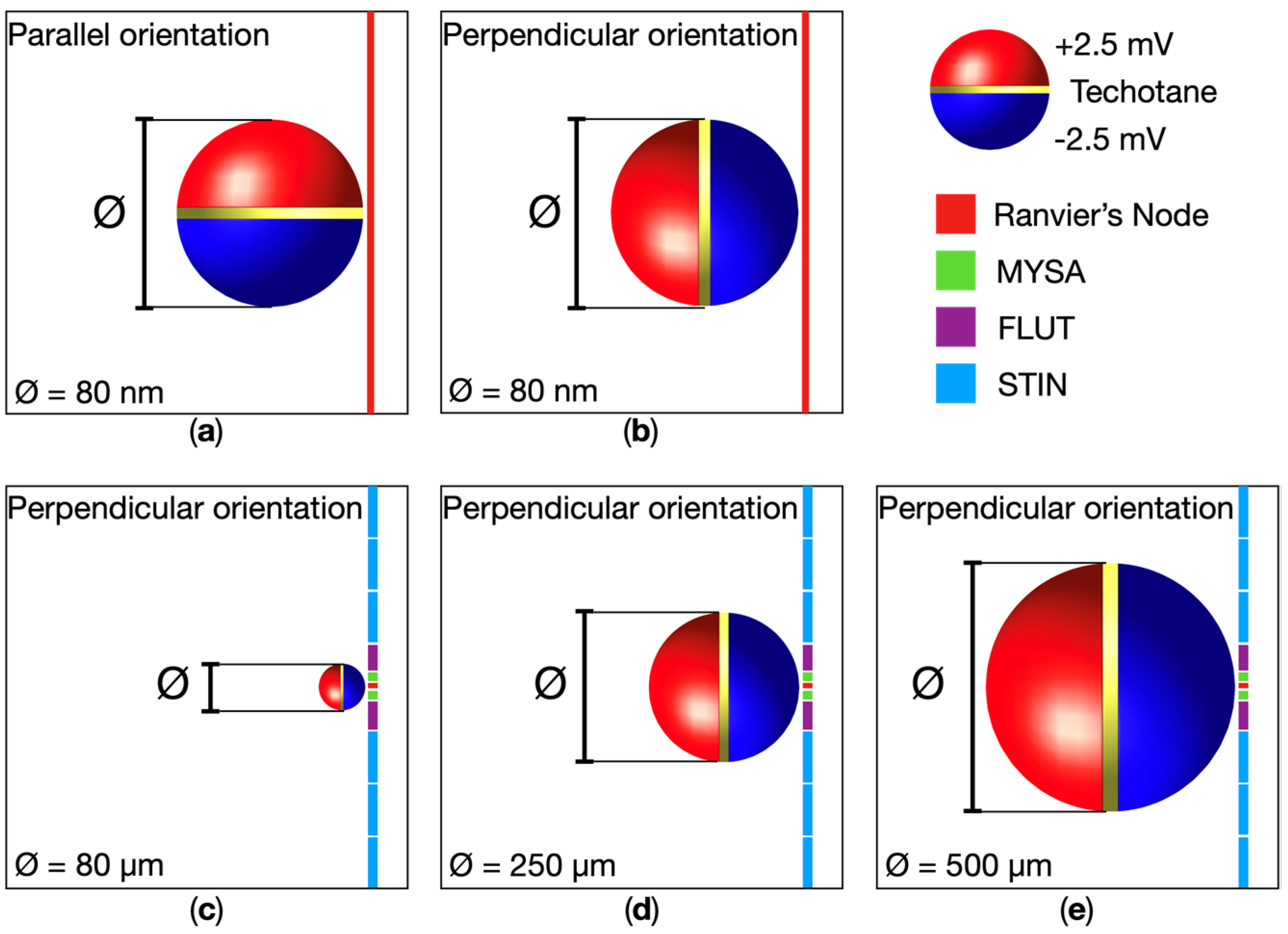
Figure 1. Schematic representation of MENP and MENPs clusters configurations localized in proximity of a Ranvier’s node of a neural fiber when the potential distribution over the MENPs’ surface reach its maximum amplitude. The MENP–fiber distance is 1R. The background represents the fascicle’s tissue, and the nodal and non-nodal segments of the neural fiber’s dynamic model are explicated. The latter consist of paranodal myelin attachments (MYSA), paranodal main segments (FLUT), and internodal segments (STIN). (a) 80 nm single MENP parallelly oriented to the neural fiber; (b) 80 nm single MENP perpendicularly oriented to the neural fiber; (c) 80-μm, (d) 250-μm, and (e) 500-μm clusters of MENPs with perpendicular orientation to the neural fiber.
Applsci 14 05372 g001
Figure 2. (a) Peripheral nerve’s realistic model and zoomed transversal section; (b) a fascicle of fibers and detail of the neural fibers.
Applsci 14 05372 g002
Figure 3. Motor (MRG) model of the neural fibers. On the top, the sequence of the nodal and non-nodal segments of the model. At the bottom, the electrical equivalent circuit of the MRG model. Each Ranvier’s node is surrounded by 10 internodal sections: 2 paranodal myelin attachments (MYSA), 2 paranodal main segments (FLUT), and 6 internodal segments (STIN), split on the two sides of the nodal section. The non-nodal segments consist of a double-cable structure explicitly representing the myelin sheath and the underlying axolemma and both including a linear conductance in parallel with the membrane capacitance. V r is the membrane potential at rest of the neural fiber. The non-linear dynamic of the Ranvier’s node includes fast (Naf) and persistent (Nap) sodium, slow potassium (Ks), and linear leakage (Lk) channels in parallel with the nodal capacitance C n . Φ e , Φ p and Φ i represent the extracellular potential, the peri-axonal potential, and the intracellular potential, respectively, while I i n t corresponds to the equivalent injected current in the intracellular space.
Applsci 14 05372 g003
Figure 4. Comparison of electric potential φ along the neural fiber for different MENPs’ configurations. (a) Single MENP at distance 2R with perpendicular orientation; (b) 80 μm MENPs cluster at distance 2R perpendicularly oriented; (c) 80 μm MENPs cluster at distance 2R parallelly oriented. The Ranvier’s node middle point, highlighted in the plots, is aligned to the MENP or MENPs cluster center.
Applsci 14 05372 g004
Figure 5. Cross-sections of a fascicle injected with the MENPs: the recruited volume and the corresponding M F values are represented for each MENPs’ configuration.
Applsci 14 05372 g005
Figure 6. Comparison of injected current I i n t along the neural fiber for different MENPs’ configurations. (a) Single MENP at distance 1R with perpendicular orientation; (b) 500 μm MENPs cluster at distance 1R perpendicularly oriented.
Applsci 14 05372 g006
Table 1. MENPs’ configurations.
Dipole DiameterParallel OrientationPerpendicular Orientation
MENP–Fiber DistanceMENP–Fiber Distance
80 nm1R1R, 2R, 3R
80 μm1R, 2R, 3R1R, 2R, 3R
250 μm1R, 2R, 3R1R, 2R, 3R
500 μm1R, 2R, 3R1R, 2R, 3R
Table 2. Multiplication factors for different MENPs dimensions and orientations.
MENPs–Fiber DistancePerpendicular OrientationParallel Orientation
MENP 80 nm1R4.84.7
2R13.7
3R31.1
Cluster 80 μm1R5.87.9
2R16.767.9
3R34.285.8
Cluster 250 μm1R5.76.3
2R13.222
3R21.945
Cluster 500 μm1R2.93.9
2R7.423.5
3R27.817.2
Disclaimer/Publisher’s Note: The statements, opinions and data contained in all publications are solely those of the individual author(s) and contributor(s) and not of MDPI and/or the editor(s). MDPI and/or the editor(s) disclaim responsibility for any injury to people or property resulting from any ideas, methods, instructions or products referred to in the content.

