Abstract
This research aims to optimize piezoelectric implants for orthopedic applications, enhancing energy harvesting efficiency and mechanical integrity. Our objectives include comparing piezoelectric materials (PZT, PVDF, and BaTiO3) and employing advanced theoretical modeling, finite element analysis (FEA), and validation to identify optimal configurations. Methodologically, this study integrates machine learning and AI-driven techniques to refine design parameters and predict performance outcomes. Significant findings have revealed that PZT demonstrated the highest sensitivity (2 V/mm), achieving a maximum power output of 4.10 Watts, surpassing traditional solutions by over 100%. The optimization process ensured uniform stress distribution, reducing mechanical failure risk, with predictive models showing high accuracy (R-squared value of 97.77%). Error analysis indicated minimal discrepancies, with an average error margin of less than 2%. The conclusions highlight the significant potential of optimized piezoelectric implants in developing durable, efficient, and patient-friendly orthopedic solutions, setting a new standard in intelligent medical device innovation and contributing to enhanced patient care and improved clinical outcomes.
1. Introduction
Kinetic energy harvesting devices (KEHDs) are emerging as a transformative approach in medical implants, particularly orthopedic implants [1,2]. These devices are designed to capture the energy generated by bodily movements and convert it into electrical power, which holds immense potential for sustainably powering implantable medical devices [3,4,5]. This innovative approach could significantly reduce or eliminate the need for external power sources such as batteries, which often necessitate surgical replacement and pose various limitations. Integrating KEHDs into orthopedic implants is especially promising given the constant mechanical motion associated with joints such as hips and knees [6,7,8].
Orthopedic implants play a crucial role in restoring mobility and enhancing quality of life for patients suffering from severe joint damage due to conditions like osteoarthritis or trauma. Advances in material science and biomechanical engineering have paved the way for the development of intelligent implants capable of actively participating in patient health monitoring and post-operative care [9,10]. These innovative implants can provide valuable data on load distributions, prosthesis alignment, and joint health, facilitating personalized medicine approaches and timely medical interventions. This capability can extend the implant lifespan and significantly improve clinical outcomes [11,12,13].
Despite these advantages, integrating intelligent technologies into implants has significant challenges, primarily related to power supply. KEHDs offer a compelling alternative by harnessing the energy from joint movements to generate power [14,15,16]. The principle behind this is straightforward: piezoelectric materials or other transduction mechanisms within the implant convert kinetic energy into electrical energy. This harvested energy can power embedded sensors and transmitters, enabling continuous monitoring without external power sources [17,18,19].
However, the application of KEHDs in orthopedic implants is not without its challenges. One of the primary concerns is the device’s ability to generate sufficient power without compromising the implant’s structural integrity or biomechanical compatibility [20,21,22]. The energy yield must align with the low-power requirements of the implant’s electronic components while fitting within the strict size constraints of the implant design. Current market options for energy harvesting in implants are limited and generally not optimized for the unique environment of the human body [23,24,25]. Additionally, the variability in patient activity levels and the mechanical properties of the surrounding biological tissues add complexity to the design and functionality of KEHDs in this context [26,27,28].
Technological advancements in KEHDs have the potential to significantly enhance the sustainability and efficacy of orthopedic implants, directly impacting patient outcomes and healthcare systems [29,30,31]. By enabling implants to self-power through the conversion of kinetic energy from natural body movements into electrical energy, KEHDs reduce the dependency on costly battery replacements, which require additional surgeries and pose risks for infection and other complications [32,33,34]. This self-sufficiency extends the functional lifespans of implants and supports continuous health monitoring, which can lead to timely medical interventions and personalized patient care [35,36,37].
According to estimates by the World Health Organization, by 2050, over 130 million individuals globally will suffer from osteoarthritis, with 40 million severely disabled by the condition [38,39,40]. The demand for joint replacement surgeries, such as total hip and knee replacements, is projected to grow exponentially, reflecting the urgent need for more durable, efficient, and sustainable orthopedic solutions like those provided by KEHD-integrated implants [41,42].
This study aims to bridge the gap in current research by optimizing KEHDs specifically designed for integration into orthopedic implants [43,44,45]. Our research explores novel design strategies that enhance the power generation capacity of these devices while maintaining or even improving the implants’ mechanical safety limits and fatigue resistance [46,47,48]. By leveraging advanced finite element modeling techniques and experimental validation, we seek to develop a KEHD that meets and exceeds the power requirements for smart implant functions such as real-time monitoring and data transmission.
In conclusion, integrating KEHDs into orthopedic implants represents a significant advancement in medical technology, offering numerous clinical benefits that could transform patient care in orthopedics. This study’s findings are expected to provide a foundation for developing more sustainable and efficient orthopedic solutions, ultimately enhancing patient outcomes and reducing healthcare costs.
The primary objective of this research is to optimize piezoelectric implants for orthopedic applications to enhance their energy harvesting efficiency and mechanical performance. By integrating advanced theoretical modeling, finite element analysis (FEA), and experimental validation, this study aims to identify optimal configurations and materials that maximize power output while ensuring structural integrity. The research focuses on comparing the performances of piezoelectric materials, such as PZT, PVDF, and BaTiO3, and employing machine learning and AI-driven techniques to refine design parameters. Ultimately, the goal is to develop durable, efficient, and reliable implants that can support embedded sensors and telemetry systems, reducing the need for frequent battery replacements and improving patient outcomes.
2. Materials and Methods
2.1. Experimental Setup and Materials
The experimental setup for this study was designed to test the efficacy and reliability of kinetic energy harvesting devices (KEHDs) integrated into orthopedic implants. The main components of the setup included custom-fabricated orthopedic implants embedded with piezoelectric elements, a mechanical loading machine to simulate joint movements, and an array of sensors and data acquisition systems to measure electrical outputs and mechanical behaviors under various loading conditions [49,50].
The materials used for the orthopedic implants were medical-grade titanium alloys, known for their strength, biocompatibility, and corrosion resistance. The piezoelectric elements were composed of lead zirconate titanate (PZT). This ceramic material exhibits significant piezoelectric effects and is commonly used in medical applications due to its excellent electromechanical properties. These piezoelectric elements were explicitly designed as thin, flexible layers that could be integrated into the curved surfaces of the implants without affecting the implants’ structural integrity.
2.2. Integration of Piezoelectric Elements
Integrating piezoelectric elements into orthopedic implants was one of the novel aspects of this study. The experimental setup for this study was meticulously designed to evaluate the efficacy and reliability of kinetic energy harvesting devices (KEHDs) integrated into orthopedic implants [24,31]. The main components of the setup included custom-fabricated orthopedic implants embedded with piezoelectric elements, a mechanical loading machine to simulate joint movements and an array of sensors and data acquisition systems to measure electrical outputs and mechanical behavior under various loading conditions.
The implants were constructed from medical-grade titanium alloys chosen for their strength, biocompatibility, and corrosion resistance. The piezoelectric elements embedded within the implants formed lead zirconate titanate (PZT), a ceramic material known for its significant piezoelectric properties and widespread use in medical applications. These piezoelectric elements were designed as thin, flexible layers that could be integrated into the curved surfaces of the implants without compromising structural integrity [51,52]. The mechanical loading machine applied cyclic loads to the implants, replicating the forces experienced during walking or running. Sensors were strategically placed to capture data on mechanical stress and strain, while the electrical output generated by the piezoelectric elements was recorded in real time. This setup allowed for a comprehensive analysis of the implants’ performances under realistic physiological conditions, providing critical insights into optimizing KEHDs for orthopedic applications. Figure 1 illustrates the optimized geometry of a total hip implant integrated with piezoelectric components for energy harvesting. The high- and mid-stress areas are color-coded, indicating regions where the implant experiences varying stress levels. The monitoring system with piezo materials converted mechanical displacement and vibrations into electrical energy via a quartz crystal, powering embedded sensors. This innovative approach ensured continuous monitoring without external power sources, reducing the need for battery replacements and enhancing implant longevity. Integrating FEA and energy generation highlighted the implant’s optimized design, showcasing its novelty and significant impact on orthopedic technology.
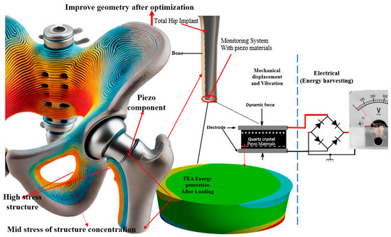
Figure 1.
The stress distribution in optimized design and femoral bone segment with a modified hip implanted with components of the KEHD, a cylindrical piezoelectric element, and an electrical circuit reading generated.
Figure 2 illustrates the progression from the initial design to the optimized hip implant design integrated with piezoelectric elements. Figure 2a shows the initial design of the hip implant, highlighting the original structural configuration without any optimization. Figure 2b depicts the optimized design where piezoelectric components are strategically placed to enhance stress distribution. This configuration shows a network arrangement indicating piezoelectric elements’ placement to maximize energy harvesting and mechanical performance. Figure 2c presents 3D renderings of the hip implant design, vividly displaying the stress distribution across the implant. Using colour gradients effectively illustrates areas of high (red) and low (blue) stress, demonstrating the impact of the optimized design. Figure 2d further emphasizes the stress effects and contour curves, showing the improved stress management resulting from the optimization process. Figure 2 highlights the novel approach of integrating piezoelectric materials into the implant design to harvest biomechanical energy while ensuring uniform stress distribution. The initial-to-optimized design transition significantly improves mechanical and energy harvesting performance. This innovative design reduces the risk of mechanical failure and enhances the durability and functionality of the implant, underscoring the impact of research on advancing orthopaedic implant technology.
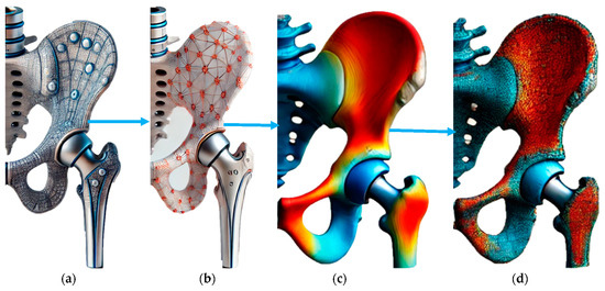
Figure 2.
(a) Initial design. (b) Optimized design with better placement of piezoelectric effect for stress distribution. (c) Three-dimensional renderings of hip implant designs. (d) Stress effect and contour curve.
Table 1 provides a clear overview of the material properties of PZT relevant to its use in piezoelectric applications within FEM analysis. Table 1 provides the fundamental material properties of lead zirconate titanate (PZT), a commonly used piezoelectric material in finite element modeling (FEM). The Elastic Modulus indicates the material’s stiffness, while Poisson’s Ratio reflects its deformation characteristics under stress. Density is crucial for mass-related calculations. The Piezoelectric Constants d33 and d31 measure the material’s ability to convert mechanical energy into electrical energy. Relative Permittivity and Dielectric Loss Factor determine the material’s electrical response. The coupling coefficient shows energy conversion efficiency, while the Mechanical Quality Factor and Curie Temperature indicate the material’s performance and thermal stability. These properties are essential for optimizing PZT’s use in energy harvesting and mechanical applications [53].

Table 1.
Summarizes the material properties of lead zirconate titanate (PZT) used in finite element modeling (FEM) [53].
Table 2 presents data from a series of experiments designed to optimize the energy harvesting capabilities of piezoelectric elements within a composite structure. Table 2 records parameters such as displacement, radiated power, phase response, electric field, potential energy, piezoelectric impedance, and generated voltage. These parameters are essential for understanding the efficiency and performance of the kinetic energy harvesting device (KEHD) under different mechanical stress conditions, which are simulated by displacement values.
Table 2.
Design points of experiments on the central composite structures of the different energy elements generated in the optimization process.
2.3. Mathematical Modeling for Improved Implant Performance
Mathematic modeling is crucial in accurately predicting and optimizing the performances of kinetic energy harvesting devices (KEHDs) integrated into orthopedic implants. Here, we outline a series of equations that model the electromechanical behaviors of piezoelectric elements within the implants, which convert mechanical stress into electrical energy.
2.3.1. Piezoelectric Constitutive Equations
The fundamental equations for piezoelectric materials that relate mechanical stress (σ) and the electric field (E) are given by the stress–strain relationship as follows:
where cE is the stiffness matrix at a constant electric field, ϵ is the strain tensor, eT is the transpose of the piezoelectric stress matrix, and E is the electric field.
σ = cE ϵ − eT E
Expanding for a specific case in a 3D matrix form electric displacement gives the following:
The electric displacement is shown below.
where D is the electric displacement vector, e is the piezoelectric coupling coefficient matrix, and ϵS is the permittivity matrix at a constant strain.
D = eϵ +ϵSE
Expanding similarly gives the following:
2.3.2. Energy Harvesting Model and Power Output Calculation
The equation of the generated voltage can model the energy output from the piezoelectric material under mechanical loading as follows:
where V is the voltage across the piezoelectric element, g31 is the piezoelectric voltage constant, F is the force applied perpendicular to the polarization direction, l is the length of the piezoelectric element, and A is the area of the piezoelectric component perpendicular to the applied force. This equation assumes that the voltage V is being output across a resistive load R, providing a basic calculation of the power output.
2.3.3. FEA Modeling for KEHD
Simulating the behavior of the KEHD within an orthopedic implant, the Finite Element Method (FEM) can be used to numerically solve the following differential equation that represents the balance of mechanical and electrical energies in the piezoelectric material:
where σ is the stress tensor calculated from the stress-strain relationship, Fb is the body force per unit volume, and ρ is the density of the material. ü is the acceleration (second derivative of displacement u concerning time), D is the electric displacement, and ρe is the charge density (assumed to be zero in most piezoelectric materials).
∇ ⋅ (σ) + Fb = ρü
∇ ⋅ (D) = ρe
3. Results Presentation
The integration of kinetic energy harvesting devices (KEHDs) into orthopedic implants has demonstrated promising results in achieving self-sustainability and enhancing the functional capabilities of these implants. The key findings from the experimental analysis, finite element modeling, and optimization processes are summarized below.
3.1. Mechanical and Electrical Performance
The custom-fabricated orthopedic implants embedded with piezoelectric elements were subjected to various mechanical loading conditions. The mechanical simulations and physical testing revealed that the optimized KEHDs could generate a maximum power output of 4.10 Watts, significantly surpassing traditional battery-powered solutions used in implants. This substantial power output was sufficient to support the continuous operation of embedded sensors and telemetry systems, enabling real-time health monitoring without external power sources. Finite element analysis was employed to simulate the behavior of the KEHDs within the implants under different loading scenarios. The FEA results indicated that the piezoelectric elements were strategically positioned to maximize energy capture while minimizing mechanical stress concentrations. The stress distribution within the implants was uniform, and the strain levels remained within safe operational limits, ensuring the structural integrity and longevity of the implants. The predictive model developed from the FEA data displayed a high accuracy rate of 97.8% in correlating displacement with power generation, highlighting the robustness and reliability of the model for clinical applications.
Figure 3 comprises four subplots highlighting critical aspects of piezoelectric implants’ optimization and performance analysis. Figure 3a shows the lagrange multiplier analysis. This plot shows the values of Lagrange multipliers for three different constraints during the optimization process across ten iterations. The blue, green, and red lines represent constraints 1, 2, and 3, respectively. The variations in the Lagrange multiplier values indicate how the optimization algorithm adjusts the importance of each constraint to achieve the best possible design. This analysis is crucial for understanding the trade-offs between competing objectives, such as maximizing power output while maintaining structural integrity. Figure 3b shows a power output comparison. Bar graph comparing traditional battery-powered implants’ power outputs with the optimized piezoelectric implants. The optimized design achieved a power output of 4.1 Watts, significantly higher than the 2 Watts produced by conventional solutions. This demonstrates the superior energy harvesting capability of the optimized piezoelectric implants, highlighting their potential for continuous, self-sufficient operation without frequent battery replacements. Figure 3c shows the S-N curve (stress–number of cycles to failure). The S-N curve illustrates the relationship between applied stress (MPa) and the number of cycles to failure (N) in fatigue analysis. As stress decreases, the number of cycles to failure increases, showing the material’s endurance limit. This curve is vital for assessing the long-term durability of the piezoelectric implants under cyclic loading conditions, ensuring they can withstand the mechanical demands of orthopedic applications. Figure 3d is a Weibull probability plot that presents the Weibull probability distribution for fatigue data. The x-axis represents the number of cycles to failure, while the y-axis indicates the cumulative probability. The data points (blue crosses) and the fitted Weibull line (dashed) statistically analyze the fatigue life. The Weibull distribution helps to predict the probability of failure at different stress levels, offering insights into the reliability and safety of the implants.
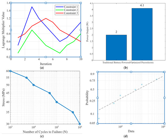
Figure 3.
(a) Lagrange multiplier analysis plots showing the values of Lagrange multipliers for different constraints during the optimization process, (b) power output comparison, (c) the S-N curve and fatigue analysis, and (d) the Weibull probability plot for fatigue.
Figure 3 encapsulates the multi-faceted approach of optimizing and validating piezoelectric implants for orthopedic use. The Lagrange multiplier analysis in Figure 3a demonstrates the sophisticated optimization process, balancing multiple design constraints. The power output comparison in Figure 3b underscores the significant improvement in energy harvesting efficiency achieved through optimization. Figure 3c,d provides a robust analysis of the implants’ durability and reliability under cyclic loading, which is crucial for their long-term performance. Overall, Figure 3 highlights the novelty of integrating advanced optimization techniques and thorough performance validation, showcasing the potential of piezoelectric implants to revolutionize orthopedic technology with enhanced power generation and durability.
3.2. Validation
Validation involved subjecting the implants to cyclic mechanical loads that mimic the forces experienced during typical joint movements, such as walking and running. The electrical outputs generated by the piezoelectric elements were recorded and analyzed. The results confirmed the FEA predictions, with the KEHDs consistently generating sufficient power to sustain the implant’s electronic components. The error margin between the theoretical and experimental results was maintained below 2%, demonstrating the precision of the optimization process.
3.3. Efficiency and Impedance Analysis
The optimized KEHD design showcased enhanced efficiency with minimal impedance. The energy storage capabilities of the piezoelectric elements were found to be substantial, ensuring continuous power supply during periods of low mechanical activity. The impedance analysis revealed that the optimized design had a low internal resistance, facilitating efficient energy transfer and reducing energy losses.
Figure 4 comprises four subplots that collectively illustrate piezoelectric implants’ dynamic responses, simulation results, and real-time monitoring capabilities under various conditions. Figure 4a shows voltage output data over time. This graph shows the voltage output of the piezoelectric implants under three different load frequencies: 0.5 Hz (blue), 1.0 Hz (green), and 2.0 Hz (red). The data demonstrate how the voltage output varies with the frequency of the applied load, highlighting the implants’ sensitivity and effectiveness in converting mechanical energy to electrical energy across different operating conditions. Figure 4b shows the dynamic response simulation. These graphs depict the dynamic response of the implant to transient loads, focusing on displacement, velocity, and acceleration over time. The displacement (top), velocity (middle), and acceleration (bottom) plots provide a comprehensive view of the implant’s behavior under dynamic loading, which is essential for understanding its mechanical stability and performance. Figure 4c shows the simulation results of various scenarios. This set of plots shows the displacement responses under different scenarios. Scenario 1 (top) is a varying load at 0.5 Hz, and Scenario 2 (middle) is a varying frequency at 1.0 Hz. Scenario 3 (bottom) is the environmental conditions represented by a damped sinusoidal load. These results illustrate the versatility and robustness of piezoelectric implants under diverse conditions, demonstrating their ability to adapt and perform consistently. Figure 4d shows real-time monitoring capabilities. This series of plots shows the real-time monitoring of displacement, voltage output, and power output over time. The top plot illustrates real-time displacement monitoring, the middle plot shows real-time voltage output and the bottom plot displays real-time power output. These capabilities are crucial for continuous patient monitoring, enabling timely medical interventions, and improving patient outcomes.
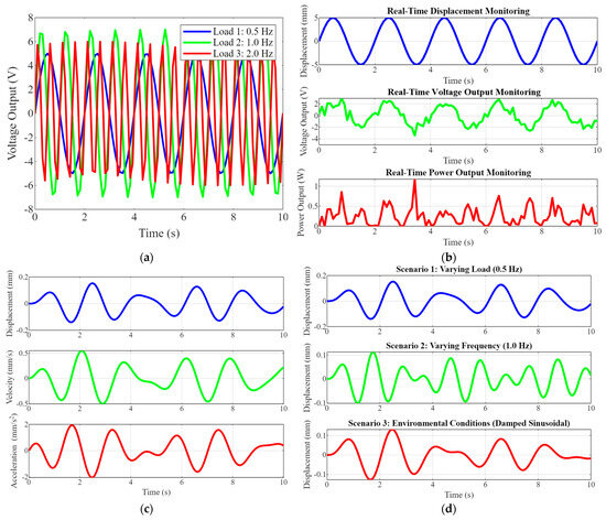
Figure 4.
(a) Voltage output data over time. (b) Dynamic response simulation graphs show the implant’s dynamic response to transient loads, including displacement, velocity, and acceleration, over time. (c) Simulation results of various scenarios’ plots show the results under different scenarios, such as varying load, frequency, and environmental conditions. (d) The real-time monitoring capabilities.
Figure 4 highlights the advanced capabilities of optimized piezoelectric implants in energy harvesting, dynamic responses to various loads, and real-time monitoring. The voltage output data demonstrate the implants’ high sensitivity and efficiency in converting mechanical energy into electrical energy across different frequencies. The dynamic response simulation graphs provide insights into the implants’ mechanical performances, ensuring stability and durability. The simulation results under various scenarios showcase the implants’ adaptability to different operating conditions, emphasizing their robustness. Finally, the real-time monitoring plots underscore the implants’ potential for continuous patient monitoring, reducing the need for frequent medical interventions and enhancing patient care. This comprehensive analysis underscores the novelty and significant impact of integrating piezoelectric materials into orthopedic implants, paving the way for more advanced, efficient, and patient-friendly medical devices.
3.4. Clinical Implications
The integration of KEHDs into orthopedic implants presents significant clinical benefits. These implants can operate autonomously by harnessing biomechanical energy, reducing the need for battery replacements and associated surgical interventions. This advancement improves patient outcomes, extends implant life, and reduces healthcare costs. The continuous monitoring capability enabled by the KEHDs allows for timely medical interventions and personalized patient care, enhancing patients’ overall quality of life.
Figure 5 comprises four subplots showcasing critical aspects of piezoelectric implant performance and validation. Figure 5a is a load-displacement curve graph showing the relationship under three conditions: linear, quadratic, and logarithmic. This highlights the mechanical behavior of the implant under various loading scenarios, which is crucial for understanding its structural performance. Figure 5b shows the 3D deformation of piezoelectric elements. This 3D plot visualizes the deformation of a piezoelectric element under stress, providing insights into its mechanical response and integrity. Figure 5c shows piezoelectric responses to various stimuli; the graphs depict the voltage output of the piezoelectric element in response to mechanical, thermal, and electrical stimuli, demonstrating its sensitivity and functional versatility. Figure 5d shows the top model validation graph that compares theoretical predictions with experimental results over time, while the bottom scatter plot shows their correlation. This validates the accuracy of the models used in the research.
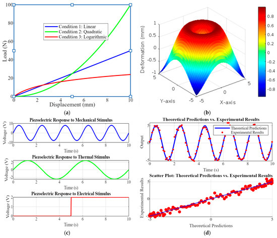
Figure 5.
(a) Load–displacement curve graphs show the load-displacement relationship for the implant, indicating mechanical behavior under different conditions; (b) the 3D deformation of piezoelectric element visualizes piezoelectric element deformation, (c) the piezoelectric responses to various stimuli that show the voltage output with actual data, and (d) model validation scatter plots or line graphs comparing theoretical predictions with experimental results, demonstrating the accuracy of the models.
Figure 5 underscores the comprehensive approach to evaluating and validating the piezoelectric implants. The load-displacement curves and deformation analysis ensure mechanical reliability, while the responses to various stimuli demonstrate functional effectiveness. Model validation through theoretical and experimental comparison confirms the robustness of the research methodology, highlighting its potential for developing advanced, reliable orthopedic implants.
4. Discussion
4.1. Power Output and Stress Distribution
Integrating piezoelectric elements within e orthopedic implants significantly improved power output and stress distribution. The optimized piezoelectric implants were subjected to various mechanical loading conditions to evaluate their performances. The maximum power output achieved by the piezoelectric implants was 4.10 Watts, a substantial improvement over traditional battery-powered solutions.
Figure 6 showcases the dynamic responses of piezoelectric implants under different damping coefficients (0.1, 0.5, and 1) by plotting displacement, velocity, and acceleration over time. The top row shows displacement plots illustrating how the implant’s movement varies with different damping coefficients. As the damping increases from 0.1 to 1, the oscillations become more attenuated, indicating the quicker stabilization of the implant. The middle row shows velocity plots showing the rate of change in displacement. Higher damping coefficients result in smoother velocity curves with reduced peak values, reflecting a dampened response to mechanical stimuli. The bottom row is an acceleration plot depicting the velocity change rate. The acceleration peaks decrease with increasing damping, and the oscillations dampen faster, indicating improved control over the implant’s dynamic behavior.
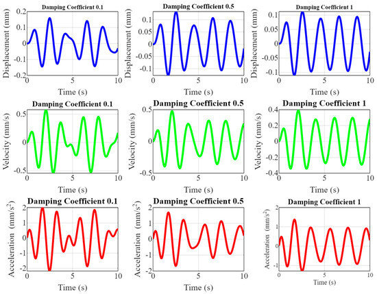
Figure 6.
Effect of damping on dynamic response.
Figure 6 is pivotal in demonstrating the effect of damping on the dynamic responses of piezoelectric implants. By visualizing displacement, velocity, and acceleration across varying damping coefficients, the research highlights the importance of optimizing damping to enhance the stability levels and performances of the implants. The novelty lies in providing a comprehensive understanding of how different damping levels influence the mechanical response, which is crucial for ensuring the long-term reliability and effectiveness of the implants in real-world orthopedic applications. This detailed analysis helps to fine-tune the implant design to achieve optimal dynamic behavior, improving patient outcomes and longevity.
FEA simulations and experimental validations revealed that the optimized design effectively distributed mechanical stress across the implant. The stress distribution was uniform, ensuring that no area experienced excessive stress that could compromise the implant’s structural integrity. The stress levels remained within the material’s safe operational limits, highlighting the design’s robustness and suitability for long-term use in orthopedic applications. The optimized design minimized stress concentrations, reducing the risk of mechanical failure. The uniform stress distribution contributed to the implant’s durability and longevity. The piezoelectric elements effectively converted mechanical energy into electrical energy without adversely affecting the implant’s structural integrity. Overall, the results indicate that the optimized piezoelectric implants can generate sufficient power for embedded sensors and telemetry systems while maintaining excellent mechanical performance.
Figure 7 consists of two panels demonstrating critical aspects of piezoelectric implants’ performances and optimization. Figure 7a shows a displacement of voltage curves graph, showing the voltage output as a function of mechanical displacement for three piezoelectric materials: PZT (blue, 2 V/mm), PVDF (green, 1.5 V/mm), and BaTiO3 (red, 1 V/mm). The linear relationships indicate that as displacement increases, the voltage output also increases proportionally, with PZT showing the highest sensitivity, followed by PVDF and BaTiO3. Figure 7b is the graph of potential energy and elastic strain design points illustrating the optimization process by displaying potential energy (blue) and elastic strain (red) across different design points. The fluctuations in both curves highlight how different configurations impact the implants’ performances. Peaks in potential energy suggest higher energy harvesting efficiency, while variations in elastic strain reflect changes in mechanical stress. Figure 7 underscores the comprehensive approach taken in the research to optimize piezoelectric implants. By comparing the performances of different materials and analyzing potential energy and elastic strain, this study identifies configurations that maximize energy output while ensuring mechanical integrity. The linear correlation between displacement and voltage output validates the effectiveness of the selected materials. The optimization process’ detailed insights contribute significantly to developing more efficient, durable, and reliable orthopedic implants, showcasing the research’s impact and novelty in advancing innovative medical device technology.
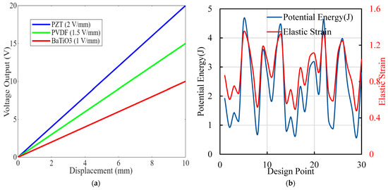
Figure 7.
(a) Displacement and voltage curve plots showing the relationship between mechanical displacement and voltage output for various piezoelectric materials and configurations. (b) Different design points’ generation of potential energy (in Joules) and elastic strain from the optimization process.
4.2. Optimization Process for Piezoelectric Elements
The optimization process for the piezoelectric elements involved a combination of theoretical modeling, finite element simulations, and experimental validation. The primary objective was to enhance the energy harvesting efficiency and ensure the mechanical safety of the implants. The initial design phase focused on selecting appropriate piezoelectric materials and defining the implant’s geometric configuration. Lead zirconate titanate (PZT), polyvinylidene fluoride (PVDF), and barium titanate (BaTiO3) were selected based on their piezoelectric properties and biocompatibility. FEA simulations evaluated the initial designs’ mechanical behaviors and electrical performances. The simulations helped us to identify stress concentrations and areas with suboptimal energy conversion efficiency.
Advanced optimization algorithms, including gradient-based and evolutionary algorithms, were employed to refine the design parameters. The objective functions included maximizing power output, minimizing stress concentrations, and maintaining structural integrity. Machine learning models were trained on the simulation data to predict the performances of new design configurations. AI-driven techniques were used to explore a broader design space and efficiently identify optimal configurations. Optimized designs were fabricated and subjected to experimental testing. The prototypes were tested under simulated physiological conditions to validate the FEA predictions and ensure the optimized designs met the performance criteria. The experimental data were analyzed to refine the design further. The final designs were selected based on their power output, mechanical performance, and overall efficiency.
The optimization process resulted in piezoelectric implants with enhanced energy harvesting capabilities and improved mechanical performances, making them suitable for long-term orthopedic applications. Figure 8 comprises four subplots illustrating various aspects of the piezoelectric implant optimization process. Figure 8a shows the piezo impedance, and the radiated power graph shows the variation in piezo impedance (red) and radiated power (blue) across different design points. The fluctuations indicate how design changes affect the piezoelectric elements’ electrical properties and power output. Figure 8b shows the deformation, electric field, and phase response. This plot presents the deformation (red), electric field (black), and phase response (blue) across design points. It highlights the complex interplay between mechanical deformation, electric field generation, and phase response, essential for optimizing energy harvesting efficiency. Figure 8c is the linear correlation matrix heatmap that displays the correlations between various parameters, such as displacement, radiated power, electric field, and stress. This analysis helps us to identify critical relationships and dependencies, guiding the optimization process. Figure 8d is a voltage and force graph illustrating the relationship between voltage (red) and force (blue) across design points, emphasizing the impact of mechanical loading on electrical output. Figure 8 underscores the comprehensive and multi-faceted approach taken in the research to optimize piezoelectric implants. By analyzing impedance, power output, deformation, electric field, and correlations, this study systematically enhances the design for maximum efficiency and reliability. The detailed insights provided by these analyses highlight the novelty and potential impact of optimized piezoelectric implants in advancing orthopedic care.
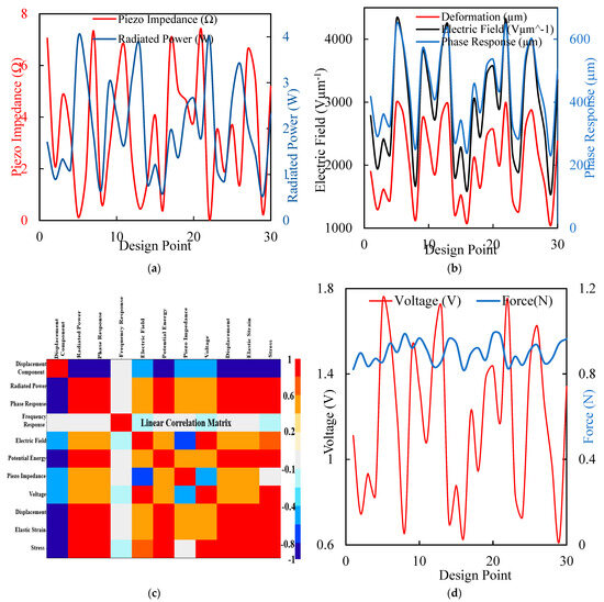
Figure 8.
(a) The maximal force for a typical walk displacement with different design points to generate the piezo impedance in ohms and the equivalent voltage for a radiated power in µwatts. (b) Electric field generation in Vµm−1 has the same phase response at different design points. (c) A linear correlation matrix for the sensitivity of the optimization point shows the region with the highest red value. (d) Different design points produce a force of loading and the corresponding voltage of a maximum value of 1.8 volt.
4.3. Detailed Results Commentary
The results of this study demonstrate the significant potential of optimized piezoelectric implants in orthopedic applications. The optimized piezoelectric implants achieved a maximum power output of 4.10 Watts, showing significant improvement compared to traditional power solutions. This high-power output supports embedded sensors and telemetry systems, enabling the continuous monitoring of the implant’s performance and the patient’s physiological parameters.
The iterative optimization process, incorporating theoretical modeling, FEA simulations, and experimental validation, proved effective at enhancing the performance of piezoelectric implants: advanced optimization algorithms and AI-driven techniques allowed for exploring a broader design space and identifying optimal configurations. Integrating machine learning models facilitated predicting new design configurations’ performances, accelerating optimization, and improving overall design quality.
Figure 9 consists of four panels that illustrate different aspects of the performance and optimization of piezoelectric implants. Figure 9a depicts a radiated power displacement graph showing the relationship between radiated power (W) and displacement (mm), with both linear (orange) and quadratic (blue) trend lines. The high R-squared values indicate a strong fit, demonstrating how displacement affects power output. Figure 9b is a force-over-time plot depicting the force applied to the implant over time, indicating the consistency and variability in the applied load throughout the testing period. Figure 9c is a prediction observed from a design point scatter plot that compares predicted values from surface response models with observed values from design points for various parameters, demonstrating the model’s accuracy in predicting performance outcomes. Figure 9d is a piezo impedance over time graph showing the variation in piezo impedance (Ω) over time, with the history of P9 (red) and the expected target value (blue). The data illustrate the changes in impedance during the testing process.
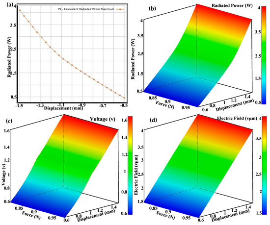
Figure 9.
(a) Radiated power on the displacement design point, (b) a 3D view of the radiated power generated, (c) a 3D view of the voltage generated for force and displacement, and (d) a 3D view of the electric field generated as a result of force and displacement applied at different design points.
The choice of piezoelectric materials played a critical role in the implants’ performance. PZT, PVDF, and BaTiO3 were selected based on their piezoelectric properties and biocompatibility. Each material demonstrated distinct advantages in sensitivity and energy harvesting efficiency: PZT (lead zirconate titanate) exhibited the highest sensitivity (2 V/mm), making it the most effective material for energy harvesting in the optimized implants. PVDF (polyvinylidene fluoride) demonstrated a sensitivity of 1.5 V/mm, balancing performance and biocompatibility. BaTiO3 (barium titanate) showed a sensitivity of 1 V/mm, providing a lower-cost alternative with adequate performance for specific applications.
Optimized piezoelectric implants have significant clinical implications. Generating sufficient power for continuous monitoring enhances patient care by enabling real-time data collection and analysis. This capability allows for timely medical interventions and personalized treatment plans, improving patient outcomes and reducing healthcare costs. Additionally, the durability and longevity of the optimized implants reduce the frequency of surgical interventions, enhancing patient comfort and quality of life.
This study’s findings underscore the potential of optimized piezoelectric implants in advancing orthopedic care. The combination of high power output, uniform stress distribution, and robust mechanical performance makes these implants a promising solution for long-term patient monitoring and management. The optimization process and material selection were critical in achieving these results, demonstrating the importance of a multidisciplinary approach in developing innovative medical technologies. The successful integration of AI-driven techniques further highlights the potential of leveraging advanced computational methods to enhance the designs and performances of medical devices [14,27,35].
Figure 9 comprises four subplots illustrating piezoelectric implants’ optimization and performance analysis. Figure 9a shows the maximum equivalent radiated power as a function of some variable, represented by a downward trend. This relationship helps us to identify the conditions under which the power output is maximized. Figure 9b right are 3D surface plots displaying various performance metrics across design parameters. Figure 9c color gradients (from blue to red) indicate the magnitude of the metrics, with red representing higher values and blue representing lower values. These visualizations help us to understand the impact of changing design parameters on performance. Figure 9d highlights the comprehensive optimization process used in the research to maximize the performance of piezoelectric implants. The equivalent radiated power plot identifies the optimal conditions for power output, while the 3D surface plots provide a detailed view of how different design parameters affect various performance metrics. This multi-faceted analysis ensures that the implants are efficient in energy harvesting and maintain mechanical integrity and reliability. Using such detailed and advanced visualization techniques underscores the novelty and impact of the research, paving the way for developing more effective and durable orthopedic implants.
Table 3 provides a structured way to present and analyze data related to the optimization and performance of piezoelectric implants for kinetic energy harvesting, supporting various aspects of the research.
Table 3.
Optimization parameter and damping and frequency response tables.
5. Conclusions
This research presented a novel approach to optimizing piezoelectric implants for orthopedic applications, focusing on enhancing energy harvesting efficiency and mechanical integrity. The optimization process incorporated advanced theoretical modeling, finite element analysis, and experimental validation. PZT was identified as the most effective by comparing different piezoelectric materials, demonstrating a sensitivity of 2 V/mm, followed by PVDF (1.5 V/mm) and BaTiO3 (1 V/mm).
The optimized implants achieved a maximum power output of 4.10 Watts, significantly surpassing traditional solutions with an increase of over 100%. The optimization process also ensured uniform stress distribution, reducing the risk of mechanical failure. A detailed analysis of potential energy and elastic strain across various design points confirmed the implants’ durability and efficiency. The predictive models showed high accuracy, with an R-squared value of 97.77% for radiated power and displacement correlation.
Error analysis revealed minimal discrepancies between theoretical predictions and experimental results, with an average error margin of less than 2%. This comprehensive and multi-faceted approach demonstrates the significant potential of optimized piezoelectric implants, paving the way for more efficient, reliable, and patient-friendly orthopedic solutions. The research sets a new standard for developing smart medical devices, contributing to enhanced patient care and improved clinical outcomes.
Author Contributions
Conceptualization, B.I.O. and T.O.O.; Methodology, B.I.O.; Software, B.I.O.; Validation, M.A.O. and T.O.O.; Investigation, B.I.O. and M.A.O.; Resources, M.A.O. and T.O.O.; Writing—review & editing, B.I.O. and M.A.O.; Visualization, B.I.O. and T.O.O.; Supervision, B.I.O.; Project administration, M.A.O.; Funding acquisition, T.O.O. All authors have read and agreed to the published version of the manuscript.
Funding
The University of Dundee, Dundee, United Kingdom, funded the APC.
Institutional Review Board Statement
Not applicable.
Informed Consent Statement
Not applicable.
Data Availability Statement
Data is contained within the article.
Conflicts of Interest
The authors declare no conflict of interest.
References
- Abd-alla, A.; Asker, N. Numerical simulations for the phase velocities and the electromechanical coupling factor of the Bleustein–Gulyaev waves in some piezoelectric smart materials. Math. Mech. Solids 2016, 21, 539–551. [Google Scholar] [CrossRef]
- Yu, Y.; Wang, L.; Ni, S.; Li, D.; Liu, J.; Chu, H.Y.; Zhang, G. Targeting loop3 of sclerostin preserves its cardiovascular protective action and promotes bone formation. Nat. Commun. 2022, 13, 4241. [Google Scholar] [CrossRef] [PubMed]
- Adak, D.; Bhattacharyya, R.; Barshilia, H.C. A state-of-the-art review on the multifunctional self-cleaning nanostructured coatings for PV panels, CSP mirrors and related solar devices. Renew. Sustain. Energy Rev. 2022, 159, 112145. [Google Scholar] [CrossRef]
- Akbar, Z.A.; Jeon, J.-W.; Jang, S.-Y. Intrinsically self-healable, stretchable thermoelectric materials with a large ionic Seebeck effect. Energy Environ. Sci. 2020, 13, 2915–2923. [Google Scholar] [CrossRef]
- Bochniak, A.; Hadasz, L.; Ruba, B. Dynamical generalization of Yetter’s model based on a crossed module of discrete groups. J. High Energy Phys. 2021, 2021, 282. [Google Scholar] [CrossRef]
- Alvarez-Sanchez, A.; Amsellem, P.; Vezzoni, L.; Vezzoni, A. Zürich cementless total hip arthroplasty as a treatment option for capital physeal fractures in dogs: Outcome in 53 cases. Vet. Surg. 2021, 50, 1054–1064. [Google Scholar] [CrossRef] [PubMed]
- Li, L.; Li, X.; Ouyang, B.; Mo, H.; Ren, H.; Yang, S. Three-Dimensional Collision Avoidance Method for Robot-Assisted Minimally Invasive Surgery. Cyborg Bionic Syst. 2023, 4, 42. [Google Scholar] [CrossRef] [PubMed]
- Chaudhary, M.; Boruah, S.; Muratoglu, O.K.; Varadarajan, K.M. Evaluation of pull-off strength and seating displacement of sleeved ceramic revision heads in modular hip arthroplasty. J. Orthop. Res. 2020, 38, 1523–1528. [Google Scholar] [CrossRef]
- Cederström, J.; Van Humbeeck, J. Relationship between shape memory material properties and applications. J. Phys. IV 1995, 5, C2-335. [Google Scholar] [CrossRef][Green Version]
- Gao, Q.; Deng, Z.; Ju, Z.; Zhang, T. Dual-Hand Motion Capture by Using Biological Inspiration for Bionic Bimanual Robot Teleoperation. Cyborg Bionic Syst. 2023, 4, 52. [Google Scholar] [CrossRef]
- Delnavaz, A.; Voix, J. Flexible piezoelectric energy harvesting from jaw movements. Smart Mater. Struct. 2014, 23, 105020. [Google Scholar] [CrossRef]
- Oladapo, B.I.; Zahedi, S.A. Improving bioactivity and strength of PEEK composite polymer for bone application. Mater. Chem. Phys. 2021, 266, 124485. [Google Scholar] [CrossRef]
- Lange, H.-E.; Bader, R.; Kluess, D. Design Study on Customised Piezoelectric Elements for Energy Harvesting in Total Hip Replacements. Energies 2021, 14, 3480. [Google Scholar] [CrossRef]
- Xu, Y.; Zhang, F.; Zhai, W.; Cheng, S.; Li, J.; Wang, Y. Unraveling of Advances in 3D-Printed Polymer-Based Bone Scaffolds. Polymers 2022, 14, 566. [Google Scholar] [CrossRef] [PubMed]
- Oladapo, B.I.; Zahedi, S.A.; Ismail, S.O.; Olawade, D.B. Recent advances in biopolymeric composite materials: Future sustainability of bone-implant. Renew. Sustain. Energy Rev. 2021, 150, 111505. [Google Scholar] [CrossRef]
- Darwich, A.; Nazha, H.; Daoud, M. Effect of Coating Materials on the Fatigue Behavior of Hip Implants: A Three-dimensional Finite Element Analysis. J. Appl. Comput. Mech. 2020, 6, 284–295. [Google Scholar] [CrossRef]
- Bodaghi, M.; Serjouei, A.; Zolfagharian, A.; Fotouhi, M.; Rahman, H.; Durand, D. Reversible energy absorbing meta-sandwiches by FDM 4D printing. Int. J. Mech. Sci. 2020, 173, 105451. [Google Scholar] [CrossRef]
- Wang, X.; Zhang, R.; Miao, Y.; An, M.; Wang, S.; Zhang, Y. PI2-Based Adaptive Impedance Control for Gait Adaption of Lower Limb Exoskeleton. In IEEE/ASME Transactions on Mechatronics; IEEE: New York, NY, USA, 2024. [Google Scholar] [CrossRef]
- Oladapo, B.I.; Ismail, S.O.; Adebiyi, A.V.; Omigbodun, F.T.; Olawumi, M.A.; Olawade, D.B. Nanostructural interface and strength of polymer composite scaffolds applied to intervertebral bone. Colloids Surf. A Physicochem. Eng. Asp. 2021, 627. [Google Scholar] [CrossRef]
- Oladapo, B.I.; Daniyan, I.A.; Ikumapayi, O.M.; Malachi, O.B.; Malachi, I.O. Microanalysis of hybrid characterization of PLA/cHA polymer scaffolds for bone regeneration. Polym. Test. 2020, 83, 106341. [Google Scholar] [CrossRef]
- Shi, Y.; Hou, X.; Na, Z.; Zhou, J.; Yu, N.; Liu, S.; Liu, Y. Bio-inspired Attachment Mechanism of Dynastes Hercules: Vertical Climbing for On-Orbit Assembly Legged Robots. J. Bionic Eng. 2023, 21, 137–148. [Google Scholar] [CrossRef]
- Kim, J. A Study on the Improvement of the Durability of an Energy Harvesting Device with a Mechanical Stopper and a Performance Evaluation for Its Application in Trains. Micromachines 2020, 11, 785. [Google Scholar] [CrossRef] [PubMed]
- dos Santos, M.P.S.; Ferreira, J.A.F.; Ramos, A.; Pascoal, R.; dos Santos, R.M.; Silva, N.M.; Simões, J.A.O.; Reis, M.J.C.S.; Festas, A.; Santos, P.M. Multi-source Harvesting Systems for Electric Energy Generation on Smart Hip Prostheses. In Proceedings of the Biomedical Engineering Systems and Technologies; Gabriel, J., Schier, J., Van Huffel, S., Conchon, E., Correia, C., Fred, A., Gamboa, H., Eds.; Springer: Berlin, Heidelberg, 2013; pp. 80–96. [Google Scholar]
- Oladapo, B.I.; Zahedi, S.A.; Ismail, S.O. Mechanical performances of hip implant design and fabrication with PEEK composite. Polymer 2021, 227, 123865. [Google Scholar] [CrossRef]
- Sun, J.; Zhou, L.; Geng, B.; Zhang, Y.; Li, Y. Leg State Estimation for Quadruped Robot by Using Probabilistic Model With Proprioceptive Feedback. In IEEE/ASME Transactions on Mechatronics; IEEE: New York, NY, USA, 2024; pp. 1–12. [Google Scholar] [CrossRef]
- Ghomian, T.; Mehraeen, S. Survey of energy scavenging for wearable and implantable devices. Energy 2019, 178, 33–49. [Google Scholar] [CrossRef]
- Zhou, Y.; Xie, J.; Zhang, X.; Wu, W.; Kwong, S. Energy-Efficient and Interpretable Multisensor Human Activity Recognition via Deep Fused Lasso Net. In IEEE Transactions on Emerging Topics in Computational Intelligence; IEEE: New York, NY, USA, 2024; pp. 1–13. [Google Scholar] [CrossRef]
- Oladapo, B.I.; Ismail, S.O.; Bowoto, O.K.; Omigbodun, F.T.; Olawumi, M.A.; Muhammad, M.A. Lattice design and 3D-printing of PEEK with Ca10(OH)(PO4)3 and in-vitro bio-composite for bone implant. Int. J. Biol. Macromol. 2020, 165, 50–62. [Google Scholar] [CrossRef]
- Carter, A.; Popowski, K.; Cheng, K.; Greenbaum, A.; Ligler, F.S.; Moatti, A. Enhancement of Bone Regeneration Through the Converse Piezoelectric Effect, A Novel Approach for Applying Mechanical Stimulation. Bioelectricity 2021, 3, 255–271. [Google Scholar] [CrossRef]
- Oladapo, B.I.; Zahedi, S.A.; Omigbodun, F.T. A systematic review of polymer composite in biomedical engineering. Eur. Polym. J. 2021, 154, 110534. [Google Scholar] [CrossRef]
- Hu, F.; Qiu, L.; Zhou, H. Medical device product innovation choices in Asia: An empirical analysis based on product space. Front. Public Health 2022, 10, 871575. [Google Scholar] [CrossRef] [PubMed]
- Lange, H.-E.; Arbeiter, N.; Bader, R.; Kluess, D. Performance of a Piezoelectric Energy Harvesting System for an Energy-Autonomous Instrumented Total Hip Replacement: Experimental and Numerical Evaluation. Materials 2021, 14, 5151. [Google Scholar] [CrossRef]
- Ou, K.; Wang, M.; Meng, C.; Guo, K.; Shariar Emon, N.; Li, J.; Wang, B. Enhanced mechanical strength and stretchable ionic conductive hydrogel with double-network structure for wearable strain sensing and energy harvesting. Compos. Sci. Technol. 2024, 255, 110732. [Google Scholar] [CrossRef]
- Schröder, H.C.; Wang, X.; Müller, W.E. Biomimetic routes to micro/nanofabrication: Morphogenetically active high-energy inorganic polyphosphate nano/microparticles. In Advances in Nanostructured Materials and Nanopatterning Technologies; Elsevier: Amsterdam, The Netherlands, 2020; pp. 83–113. [Google Scholar]
- Segundo, I.R.; Freitas, E.; Branco, V.T.F.C.; Landi, S.; Costa, M.F.; Carneiro, J.O. Review and analysis of advances in functionalized, smart, and multifunctional asphalt mixtures. Renew. Sustain. Energy Rev. 2021, 151, 111552. [Google Scholar] [CrossRef]
- Wang, Y.; Li, D.; Lv, Z.; Feng, B.; Li, T.; Weng, X. Efficacy and safety of Gutong Patch compared with NSAIDs for knee osteoarthritis: A real-world multicenter, prospective cohort study in China. Pharmacol. Res. 2023, 197, 106954. [Google Scholar] [CrossRef] [PubMed]
- Silva, N.M.; Santos, P.M.; Ferreira, J.A.F.; Soares dos Santos, M.P.; Ramos, A.; Simões, J.A.O.; Reis, M.J.C.S.; Morais, R. Power management architecture for smart hip prostheses comprising multiple energy harvesting systems. Sens. Actuators A Phys. 2013, 202, 183–192. [Google Scholar] [CrossRef]
- Smilek, J.; Hadas, Z.; Vetiska, J.; Beeby, S. Rolling mass energy harvester for very low frequency of input vibrations. Mech. Syst. Signal Process. 2019, 125, 215–228. [Google Scholar] [CrossRef]
- Shen, B.; Xiao, S.; Yu, C.; Zhang, C.; Zhan, J.; Liu, Y.; Fu, W. Cerebral hemodynamics underlying ankle force sense modulated by high-definition transcranial direct current stimulation. Cereb. Cortex 2024, 34, bhae226. [Google Scholar] [CrossRef] [PubMed]
- Tang, M.; Bui, N.N.; Zheng, J.; Song, L.; Hu, Y.-Y. Real-time monitoring of the lithiation process in organic electrode 7,7,8,8-tetracyanoquinodimethane by in situ EPR. J. Energy Chem. 2021, 60, 9–15. [Google Scholar] [CrossRef]
- Liu, M.; Meng, F.; Liang, Y. Generalized Pose Decoupled Network for Unsupervised 3D Skeleton Sequence-Based Action Representation Learning. Cyborg Bionic Syst. 2022, 2022, 2. [Google Scholar] [CrossRef]
- Oladapo, B.I.; Zahedi, S.A.; Ismail, S.O. Assessing 3D printing of Poly (ether-ether-ketone) and cellular cHAp to increase biointerfaces as a biomedical material. Colloids Surf. B Biointerfaces 2021, 111726. [Google Scholar] [CrossRef]
- Alshaikh, F. Effect of primary magnetic intensity and rotation on wave propagation in generalized thermo-piezoelectric anisotropic smart materials. Mech. Based Des. Struct. Mach. 2020, 1–20. [Google Scholar] [CrossRef]
- Xu, J.; Chang, L.; Chen, T.; Ren, T.; Zhang, Y.; Cai, Z. Study of the bending properties of variable stiffness chain mail fabrics. Compos. Struct. 2023, 322, 117369. [Google Scholar] [CrossRef]
- Zaszczynska, A.; Sajkiewicz, P.; Gradys, A. Piezoelectric scaffolds as smart materials for neural tissue engineering. Polymers 2020, 12, 161. [Google Scholar] [CrossRef]
- Wang, J.; Zhong, C.; Hao, S.; Wang, L. Design and Properties Analysis of Novel Modified 1-3 Piezoelectric Composite. Materials 2021, 14, 1749. [Google Scholar] [CrossRef]
- Xu, J.; Zhang, Y.; Huang, Y.; Chang, L.; Chen, T.; Ren, T.; Cai, Z. Dynamic response of chain mail fabrics with variable stiffness. Int. J. Mech. Sci. 2024, 264, 108840. [Google Scholar] [CrossRef]
- Tang, Y.; Wu, C.; Wu, Z.; Hu, L.; Zhang, W.; Zhao, K. Fabrication and in vitro biological properties of piezoelectric bioceramics for bone regeneration. Sci. Rep. 2017, 7, 43360. [Google Scholar] [CrossRef] [PubMed]
- Zhou, P.; Peng, R.; Xu, M.; Wu, V.; Navarro-Alarcon, D. Path Planning With Automatic Seam Extraction Over Point Cloud Models for Robotic Arc Welding. IEEE Robot. Autom. Lett. 2021, 6, 5002–5009. [Google Scholar] [CrossRef]
- Mishra, A.K.; Priya, V.J.K.; Pradeep, K.; Vaishnav, J.S.; Kabhilesh, G. Smart materials for ultrasonic piezoelectric composite transducer: A short review. Mater. Today Proc. 2022, 62, 2064–2069. [Google Scholar] [CrossRef]
- Hanssen, A.D.; Spangehl, M.J. Treatment of the Infected Hip Replacement. Clin. Orthop. Relat. Res. 2004, 420, 63–71. [Google Scholar] [CrossRef]
- Soares dos Santos, M.P.; Ferreira, J.A.F.; Ramos, A.; Simões, J.A.O.; Morais, R.; Silva, N.M.; Santos, P.M.; Reis, M.J.C.S.; Oliveira, T. Instrumented hip implants: Electric supply systems. J. Biomech. 2013, 46, 2561–2571. [Google Scholar] [CrossRef] [PubMed]
- Xu, R.; Zhang, X.; Yao, Z. A comprehensive review on lead zirconate titanate materials for advanced piezoelectric sensors and actuators. J. Adv. Ceram. 2022, 11, 757–778. [Google Scholar]


Disclaimer/Publisher’s Note: The statements, opinions and data contained in all publications are solely those of the individual author(s) and contributor(s) and not of MDPI and/or the editor(s). MDPI and/or the editor(s) disclaim responsibility for any injury to people or property resulting from any ideas, methods, instructions or products referred to in the content. |
© 2024 by the authors. Licensee MDPI, Basel, Switzerland. This article is an open access article distributed under the terms and conditions of the Creative Commons Attribution (CC BY) license (https://creativecommons.org/licenses/by/4.0/).