Article

Design of Typhoon Detection Downcast Device Based on Four-Arm Helical Antenna Structure

by
Tao Hong
,
Zhiyan Lin
*,
Yi Li
and
Tong Liu
School of Electronics and Information Engineering, Beihang University, Beijing 100191, China
*
Author to whom correspondence should be addressed.
Appl. Sci. 2024, 14(17), 7956; https://doi.org/10.3390/app14177956
Submission received: 31 July 2024 / Revised: 27 August 2024 / Accepted: 28 August 2024 / Published: 6 September 2024

Abstract

:
The use of airships to launch space probes has been an effective means of conducting typhoon surveys in recent years, but the carrying area and weight of airships are very limited, so it is necessary to reduce the weight and volume of the release device as much as possible. This paper reports the first use of a probe with cylindrical and omnidirectional characteristics, as well as a four-arm spiral receiving antenna, which can also act as the downward release device of the inner wall and improve the space utilization rate. Through further analysis and improvement, it was determined that the four-armed helical antenna can be printed on the medium using a flexible material, which not only reduces the weight of the device but also avoids direct contact between the antenna and the sounding device and improves the stability of the antenna. The designed antenna was modeled and simulated using Ansys HFSS 2021 simulation software.The simulation results show that the antenna presented in this study achieves good performance at the center frequency of 403 MHz, the input voltage VSWR and return loss of the antenna are ideal, and the antenna has a good directional map.

1. Introduction

With the intensification of global climate change, the frequency and destructive power of typhoons—a form of tropical cyclone—are on the rise, posing an increasingly serious threat to human social and economic activities. The occurrence and development of these extreme weather phenomena and the changes in their paths are affected by a variety of complex factors, making the prediction of their intensity and movement paths a major challenge in the field of meteorology. Although the accuracy of typhoon track prediction has significantly improved in recent decades with the help of scientific and technological advances, especially the rapid improvement in remote sensing technology and data processing capability, there is still significant uncertainty in the prediction of typhoon intensity. The precise prediction of the intensity change of a typhoon approaching or making landfall is especially difficult, which directly affects the effective implementation of disaster prevention and mitigation measures. Early studies relied mainly on ground observations, aircraft reconnaissance, and satellite remote sensing, which provide valuable data for typhoon research but also have many limitations. For example, although reconnaissance aircraft can directly enter the eye of a typhoon to conduct measurements, this method is costly and involves safety risks; furthermore, while satellite remote sensing can provide large-scale observations, the timeliness and accuracy of the obtained data cannot meet the demands of real-time monitoring. Therefore, the development of droppable sounding devices for high-precision, real-time monitoring of the internal structure of typhoons has become an important direction in current research. Sounding instruments dropped from a designated location at high altitude have been used to measure and transmit real-time typhoon data to ground receiving stations. The United States, Germany, the Soviet Union, Finland, and France have all carried out research and development on sounding instruments and ultimately put them into use [1]. A schematic diagram of the blimp sounding procedure is shown in Figure 1.
A droppable sounding system consists of a sounding device, a release mechanism, a platform signal-forwarding device, and a ground signal-receiving device. The sounding device is divided into a slow descent device and a meteorological sensing node. The slow descent device enables the sounding device to fall down smoothly and slowly and stably obtain data from the interior of the typhoon for as long as possible. The meteorological sensing node contains the temperature, pressure, and humidity sensors; the localization and wind measurement module; processing unit, transmitter; and power supply of the sounding device [2]. In 1943, the U.S. Air Force first successfully observed an offshore typhoon by means of a droppable sounder, obtaining accurate wind, temperature, pressure, and humidity contour-line data of the typhoon’s internal structure [3]. After decades of development, Finnish droppable sounders have become the most representative sounding products in the world, although they are also very expensive [4]. For example, the RD93 sounder from Vaisala Finland can transmit its detected temperature, barometric pressure, humidity, and toilet paper in the 400 MHz band; weighs only 420 g; and has a high accuracy of 0.1 m/s [5]. The GTS1 digital sounder developed by China in the 1990s was highly accurate and fast, had anti-interference capabilities, and was close to the pinnacle of this technology at that time [1]. In 2009, China performed airborne typhoon observation using droppable devices for the first time [6]. In August 2020, the Detection Center of China Meteorological Administration (CMA) and the Meteorological Bureau of Hainan Province, jointly with Chengdu Aircraft Manufacturing Company (CAMC), successfully detected Typhoon Morakot and collected the reference data through the YINGLONG-10 UAV. In October of the same year, the Shanghai Typhoon Research Institute of China Meteorological Administration (STRI of CMA) and Sichuan Tengdun Science and Technology Company (SSTC) also utilized the TD328 UAV to observe Typhoon Morakot and detected a large amount of data before the landfall of Typhoon Nangka [7]. Since 2017, the China Meteorological Administration (CMA) has taken the lead in organizing the prototype development of a new BeiDou intelligent sounding system and has committed to upgrading the meteorological sounding service from L-band radar sounding to the BeiDou sounding observation system [8]. The meteorological sounding system based on BeiDou satellite navigation was put into service in 2023, and the vertical observation capability of the atmosphere was significantly improved [9]. In April 2024, the first BeiDou sounding observation system in Yunnan Province was completed at the Simao National High Altitude Meteorological Observation Station in Pu’er City and entered into the commissioning stage [10]. In summary, the continued development of droppable sounding systems for accurate observation of internal typhoon data is of great significance to the development of meteorological detection systems. However, the existing deployment method is to carry receivers, receiving antennas, sounders, droppable devices, etc., on airships, which not only occupy a large space but are also limited by the weight of the fuselage, which severely restricts the maximum number of sounders and the airtime of the airships and ultimately leads to a limited detection effect. Droppable devices and sounders mounted on flight equipment are often constrained in terms of size and weight, so achieving smaller, lighter equipment and more accurate detection results has become a joint research effort.
In this context, the Typhoon Tracking and Detection Instrument (TTDI), a major national scientific research instrument development project in China, was proposed with the aim of improving the real-time monitoring of the internal structure of typhoons and their environmental conditions by means of advanced meteorological detection technology, thereby providing more accurate data support for typhoon intensity prediction. The project utilizes an airborne blimp as an airborne platform equipped with an advanced droppable device and a sounding instrument, the shape and internal structure of which are shown in Figure 2. The device directly enters the core area of the typhoon for observation and real-time transmission of key parameters such as temperature, humidity, barometric pressure, and GPS positioning. This study focuses on the lightweight and integrated design of the droppable typhoon detection system and on improving the overall performance and application efficiency of the detection system through innovations in the housing structure and antenna design of the sounder. At present, the mainstream weather sounders on the market are mainly cylindrical in shape, with a length of about 20 cm, as shown in Figure 2. As the four-armed helical antenna is also cylindrical, the detection device not only has a light weight and low volume but also provides stable and accurate data transmission. This is due to the outer wall of the traditional release device being replaced with a four-armed helical antenna with optimized design parameters, with the receiver and the sounder on the upper and inner parts of the release device, respectively, and the use of materials such as EPS foam and a PVC plastic cylinder. This study details the design principle of the four-arm spiral antenna, as well as parameter estimation and a performance test carried out at 403 MHz frequency. Simulation verification of the antenna design was also carried out using Ansys HFSS 2021 software, and the feasibility and validity of the design scheme were also confirmed through a physical test.
The structure of the remainder of this paper is outlined as follows. The first part describes the current background of typhoon detection and the need for integration and lightweighting of droppable devices for typhoon detection. The second part outlines the principle of the four-armed spiral antenna used in this study and the estimation of its parameters based on the available frequencies and device dimensions. The third part describes the simulation of the preliminarily designed four-arm spiral antenna via HFSS to verify its feasibility. The fourth part summarizes the shortcomings of the antenna and describes further improvements. The fifth part provides the conclusion.

2. Theoretical Studies

2.1. Four-Armed Helical Antenna Selection

The receiving antenna is the key device of the satellite navigation system. The receiver antenna converts the received electromagnetic wave signals into electrical signals for subsequent analysis and calculation. The receiver antenna needs to meet the following requirements. First, the antenna must have the ability to receive incoming waves from the space of the upper hemisphere, especially the ability to receive electromagnetic waves with a low pitch angle; that is, the antenna should have good omnidirectionality. Secondly, the receiving antenna must have a circularly polarized radiation pattern. Unlike a linearly polarized antenna, which has constrained directional performance, a circularly polarized antenna can receive electromagnetic waves from any direction. Circularly polarized waves can also effectively resist rain and fog interference and reduce multipath reflections compared with linearly polarized waves [11].
In the field of satellite navigation, the size and volume of traditional antennas must be relatively large in order to meet the needs of practical production and general use. The requirements for antennas are becoming more and more stringent, and antennas must be small and lightweight and have good circular polarization and wide-bandwidth electrical performance [12].
The four-armed helical antenna was originally proposed by Prof. C.C. Kilgus in 1986. A four-armed spiral antenna generally consists of four identical parallel radiating metal arms, and the length of the radiating arms is an integer multiple of λ /4. This antenna is generally a circularly polarized antenna. According to the principle of circularly polarized wave forming, the four arms of the the spiral antenna must flow through the amplitude of the same phase difference of 90° of the current. According to the phase difference between the feed port of the different directions of rotation, it can form a left-handed or right-handed circularly polarized wave. The radiation direction graph of this antenna is usually heart-shaped, so it has the characteristics of a wide beam and circular polarization and is suitable for use as a receiving antenna for satellite communications. In addition, the structure of the four-armed helical antenna can be printed with flexible material, making it easier to process. It also has high machining accuracy and results in a smaller antenna, which is preferable in engineering [13]. In conclusion, the four-armed helical antenna has high practical value and is worthy of further research.

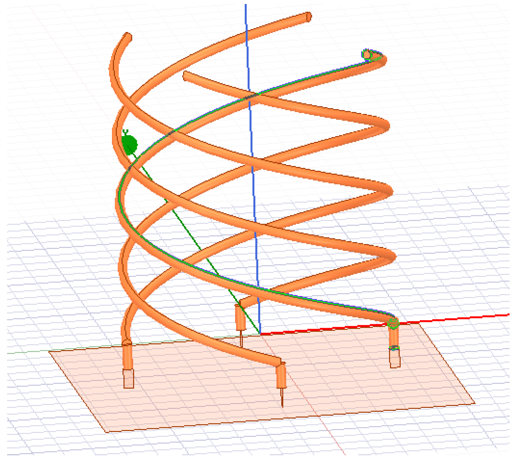
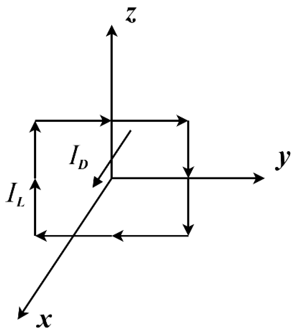
2.2. Structure of a Four-Armed Helical Antenna

The general modeling of a four-armed helical antenna is shown in Figure 3. The antenna consists of four parallel metal conductor strips of equal length, and the helical arms can be in the form of helical microstrip lines or metal spiral rods of a certain diameter [14]. If the microstrip line form is used, a dielectric plate with flexible material is generally required as the carrier plate of the microstrip line. The working wavelength of the four-armed helical antenna is related to the length of the metal conductor bar, which is generally an integer multiple of λ /4, and when N is an odd number, the top of the metal conductor bar is open-circuited; when N is an even number, the top is short-circuited.
When designing the overall dimensions of a four-armed helical antenna, the following formulas are commonly used for calculations:
L z = m 1 m 2 L l A r 2 4 π 2 r 2
where L z is the height of the spiral arm in the vertical direction, m is the number of helical turns of the spiral arm, L l is the length of the spiral arm, and r is the helical radius. When the top is open (N is odd), A is 1, and when the top is short-circuited (N is even), A is 2. The actual design process of the four-armed helical antenna generally abides by the following law [15]: When the height of the helical arm in the vertical direction ( L z ) is fixed and unchanged and when the number of spiral turns (m) of the spiral arm is fixed, the center directivity becomes stronger, and the antenna half-power beam width becomes narrower. Similarly, when the number of spiral turns (m) of the spiral arm of the antenna is fixed, the height ( L z ) of the spiral arm of the antenna is increased in the vertical direction, and a lower center directivity results in a wider beam width. Therefore, according to the application scenario of the four-arm helical antenna, high center gain can be obtained by reducing the height of the antenna and decreasing the number of helical turns (m), while uniform radiation in the upper half of the space can be achieved by increasing the height of the antenna and the number of helical turns (m). Usually, m is a half turn. At the same time, the height of the vertical direction of the spiral arm ( L z ) and the number of spiral turns (m) also affect the axis ratio of the antenna; the more turns, the higher the antenna height and polarization purity.

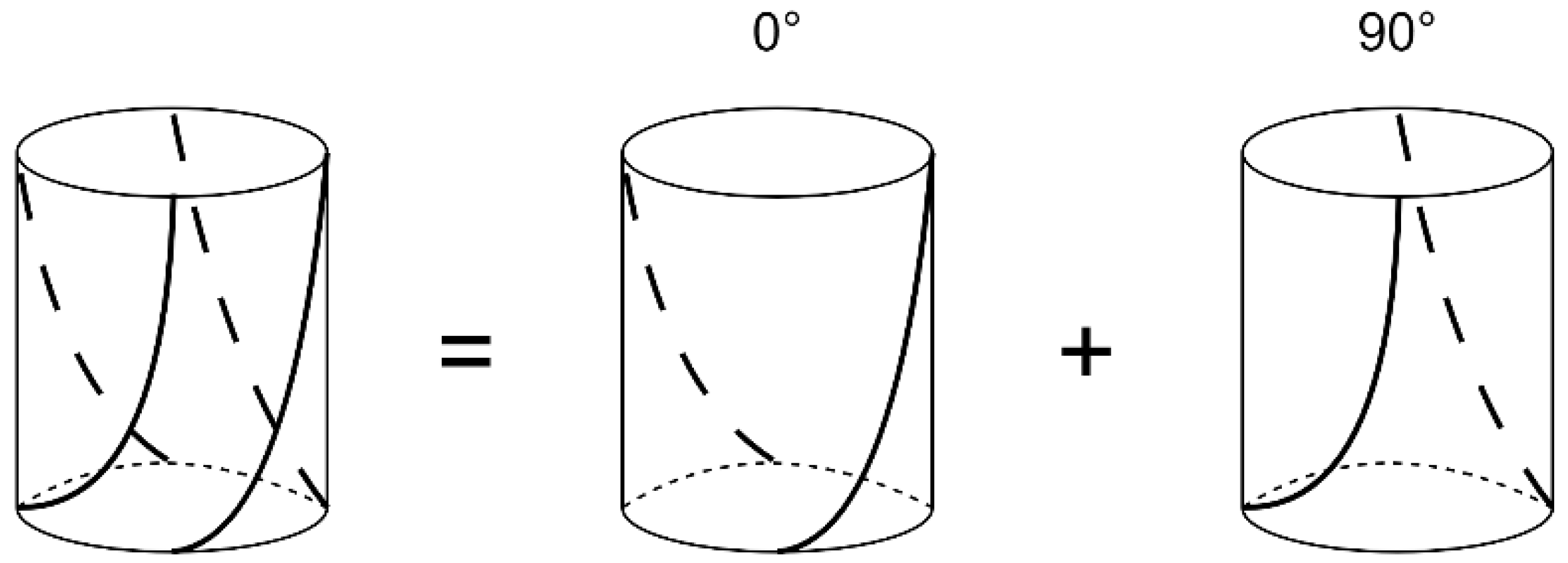
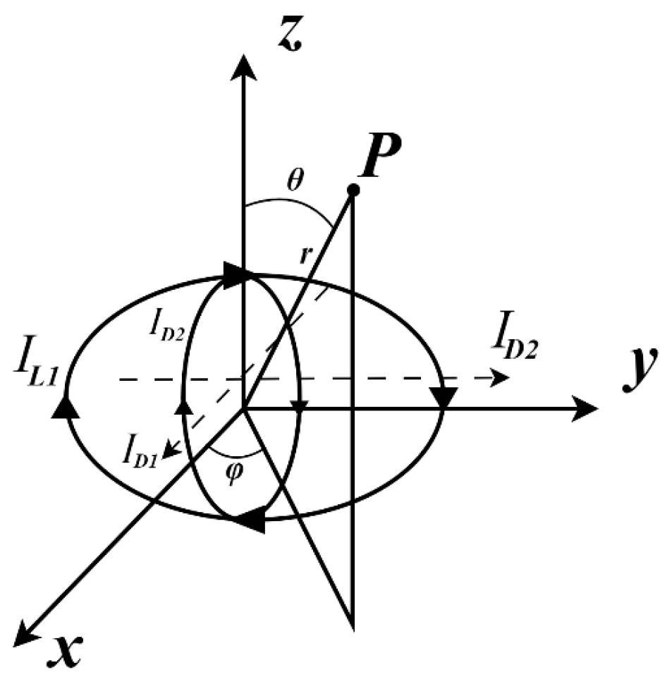
2.3. Radiation Principle of Four-Arm Helical Antenna

When introducing the radiation principle of the four-armed helical antenna, the antenna can be equated to two orthogonal two-armed helical antennas with a 90-degree phase difference [16], as shown in Figure 4.
One of the parts was selected for analysis after the structural decomposition. When the antenna works, the current density on the double-armed helix varies, as the cosine current at the middle position of the helical arm is zero, and the current at the feed point and the open and short-circuit points is maximum. Therefore, a single part can be equated with a vertically placed magnetic oscillator and a horizontally placed electric oscillator structure, as shown in Figure 5. I L is the current loop current, and I D is the electric vibrator current.
Similarly, another equivalent model can be obtained, and if the 0° and 90° equivalent models are combined, the complete four-arm helical antenna equivalent model can be achieved, as shown in Figure 6.
After simplifying the equivalent model of the four-armed helical antenna, the magnitude of the superimposed electric field at a certain position in the far-field region can be calculated using a combination of individual electromagnetic oscillators according to the following equation:
E θ = 60 π I D sin θ r L λ e j k r
E φ = 120 π 2 I L sin θ r A λ 2 e j k r
Simplification leads to the following:
E θ = j K 1 r sin θ e j k r
E φ = j K 2 r sin θ e j k r
In the above equation, L is the length of the electric oscillator; A is the area of the magnetic oscillator; λ is the working wavelength; r is the distance from any point (P) to the origin in free space; and k = 2 π / λ , and K 1 and K 2 are different constants. Then, the electric fields in the far-field region of the two equivalent models of the decomposition are expressed as follows:
E θ 1 = K 1 e j k r π 2 sin φ + j cos φ sin θ E φ 1 = K 2 e j k r π 2 cos φ cos φ j sin θ
E θ 2 = K 1 e j k r cos φ + j cos θ sin φ E φ 2 = K 2 e j k r cos θ sin φ + j cos φ
In the above equation, the addition of the e j π 2 term indicates a 90° phase shift, which is superimposed to obtain the total far-field region electric field as follows:
E θ = E θ 1 + E θ 2 = cos θ + 1 e j φ E φ = E φ 1 + E φ 2 = cos θ + 1 e j φ π 2
In the above equation, it is easy to see that the direction diagram is presented as a cardioid line, indicating that the far-field region radiation characteristics of the equivalent model of the four-armed helical antenna are equivalent to two pairs of mutually orthogonal electromagnetic oscillator antennas.

3. Preliminary Design and Simulation Verification

3.1. Design Indicators

Research on the electrical parameters of several antennas commonly used on the market in the required frequency band (around 403 MHz) revealed that most of the antenna gains are in the range of 2~8 dB, and the VSWR is less than 1.5, so the following design indices were chosen:
  • Antenna structure: four-armed spiral structure;
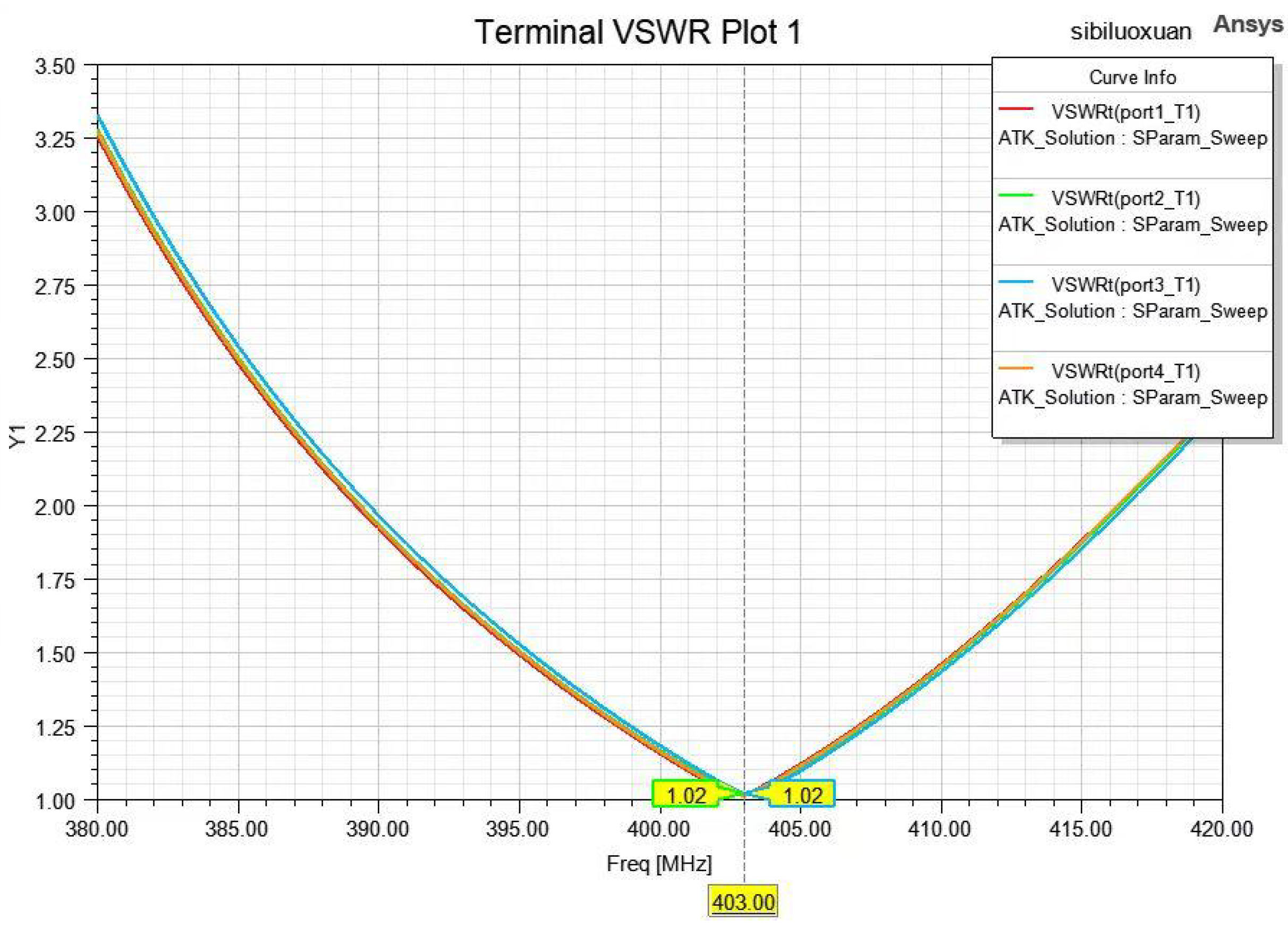
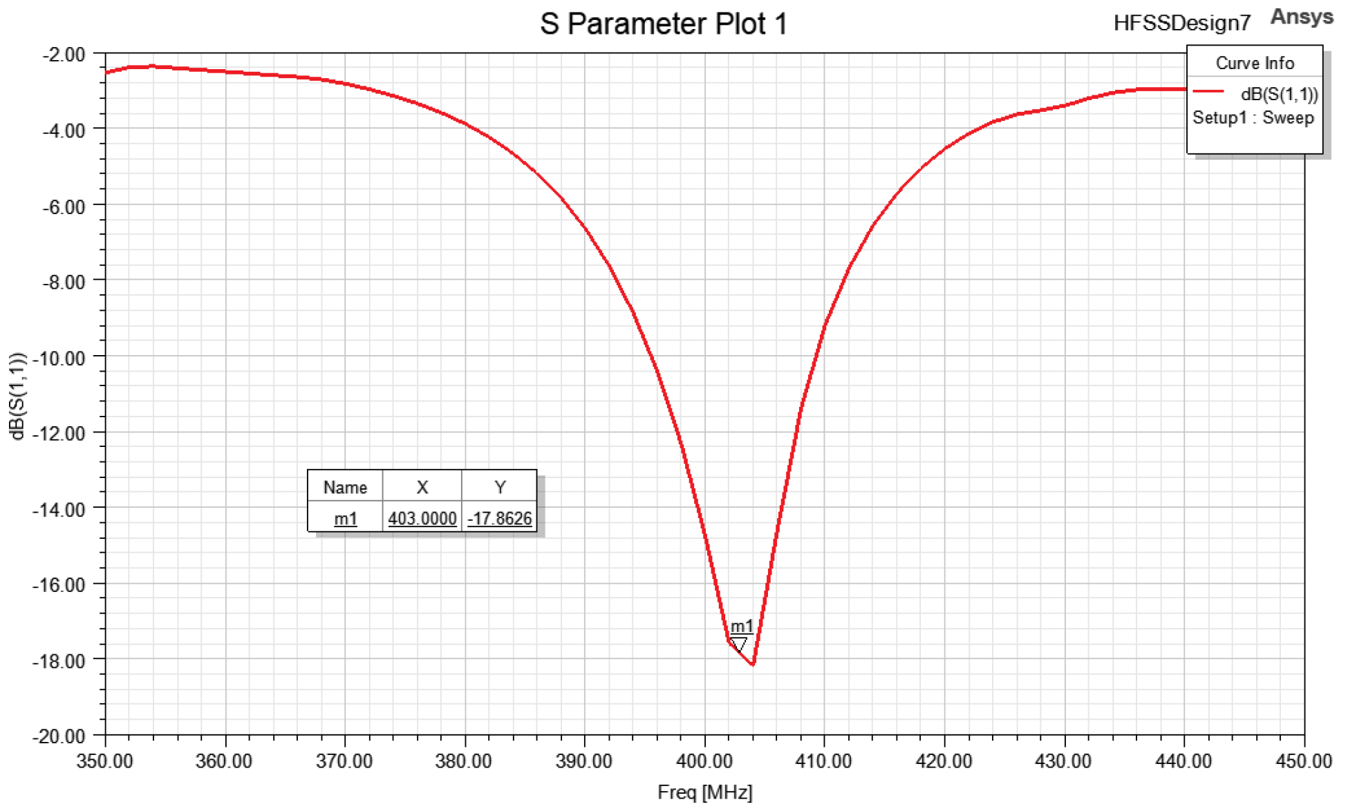
  • Signal frequency: the specified frequency of the Typhoon Project (403 MHz);
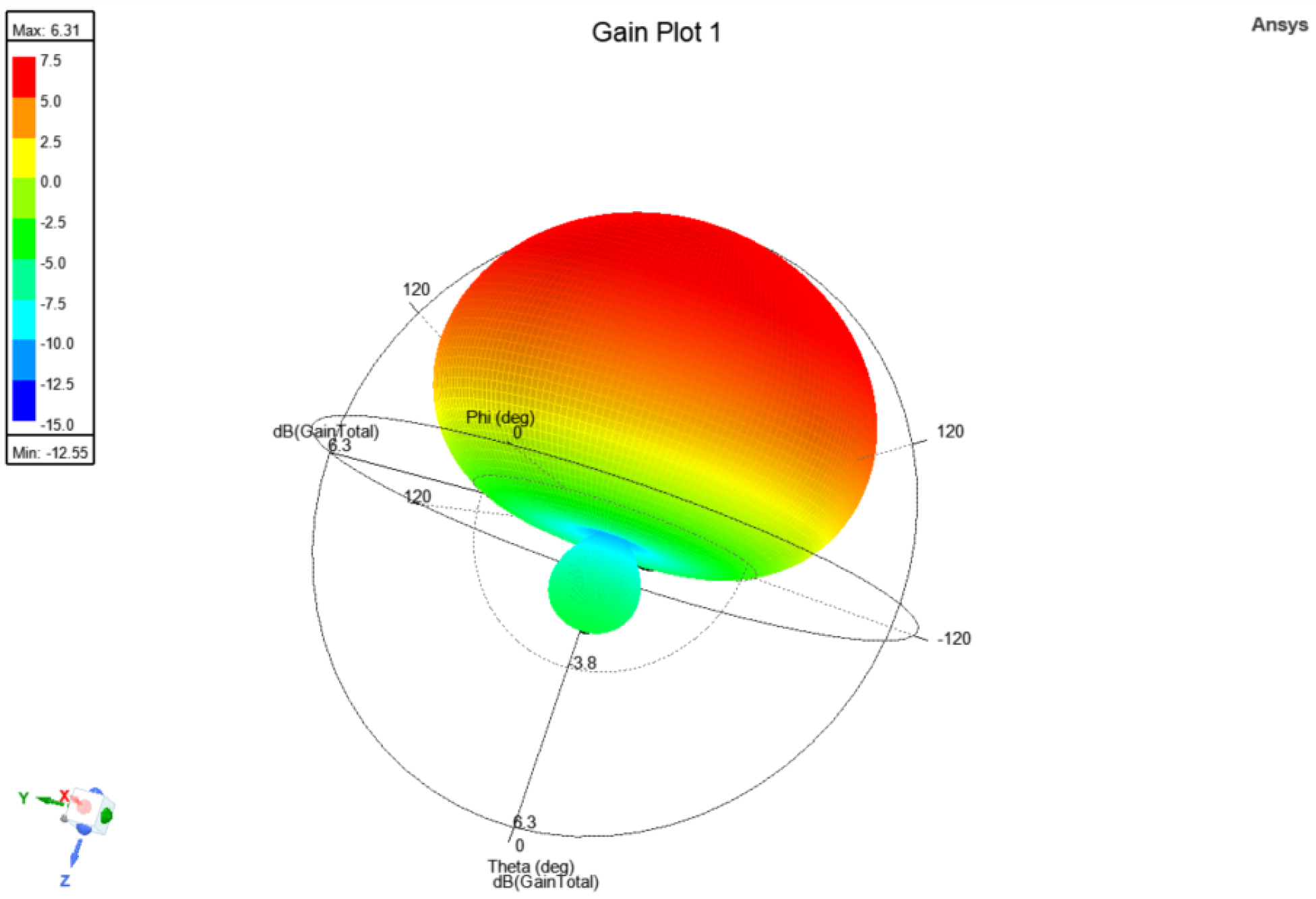
  • Maximum gain: ≥2.5 dB;
  • Polarization mode: circular polarization;
  • Antenna voltage VSWR: ≤1.5;
  • Horizontal coverage angle: 360°;
  • Return loss: ≤−10 dB;
The structural design of the antenna is based on the frequency band (403 MHz) specified by the Typhoon Project. One of the important indicators for measuring the performance of the four-armed helical antenna is to observe whether its radiation direction graph is heart-shaped or not [17]. Considering the limitation of Equation (1), the performance of the antenna, and the need to carry a cylindrical sounder with a height of about 20 cm and a radius of about 3 cm inside the antenna, the final dimensions of the antenna are calculated as follows. The height of the helical arm in the vertical direction is L z = 34.21 cm, the radius of the helix is r = 5.323 cm, and the number of helical turns of the helical arm is m = 1.1.
In the selection of the model material, the outer surface material of the cylindrical carrier wrapping the four-armed helical antenna should have good dielectric properties and the ability to adapt to temperature changes without a change in performance. Considering the requirement of the dielectric constant, polyvinyl chloride plastic with moderate cost was chosen as the material for the outer surface of the cylinder.

3.2. HFSS Modeling and Parameterization

Boundary condition settings: In reality, a helix is a three-dimensional structure. In order to facilitate the simulation calculation with a flat structure of the equivalent helix, the helix was set to the metal surface in HFSS in order to achieve the ideal simulation effect. Four spirals were selected and set to perfect E to achieve the desired effect of the metal structure.
Radiation surface settings: In principle, the radiation boundary size cannot be smaller than the distance from the antenna quarter-wavelength range according to the calculation using a radiation cylinder air box. In the establishment of the radiation cylinder, the radiation surface was added and set to Rad1.
Feed point settings: To ensure the circular polarization of the antenna’s radiation, the current amplitude of the ports of the feed to the four arms should be equal, and the phase should be two by two with a 90° difference. Four points were set at the bottom of the four-arm spiral antenna to feed each spiral arm separately.
After the setup was completed, the calculated parameters were substituted. The whole structure of the four-arm spiral antenna is shown in Figure 7.

3.3. HFSS Simulation Results

The modeled four-arm helical antenna was set up for frequency sweeping and simulation tests, and the antenna simulation focused on several results, including the return loss ( S 11 ), voltage standing-wave ratio, and the antenna directional map, as shown in Figure 8, Figure 9 and Figure 10, respectively.
Analyzing the simulation results and observing Figure 8, Figure 9 and Figure 10, it can be seen that the resonant frequency point is near 403 MHz, and the return loss, voltage VSWR, and maximum gain of the antenna’s directional map at 403 MHz can satisfy the requirements for use in terms of performance indices.
The four-arm helical antenna is used as the inner wall of the droppable release device, which has a sounder inside, a plastic protective shell outside, and a receiver above. The modeling schematic of the whole droppable device is shown in Figure 11.

4. Analysis and Improvement

Although the performance indicators meet the initial design requirements, they were only obtained from a simulation result under ideal conditions. Through further analysis of the initially designed antenna structure, it was found that there are currently two main problems.
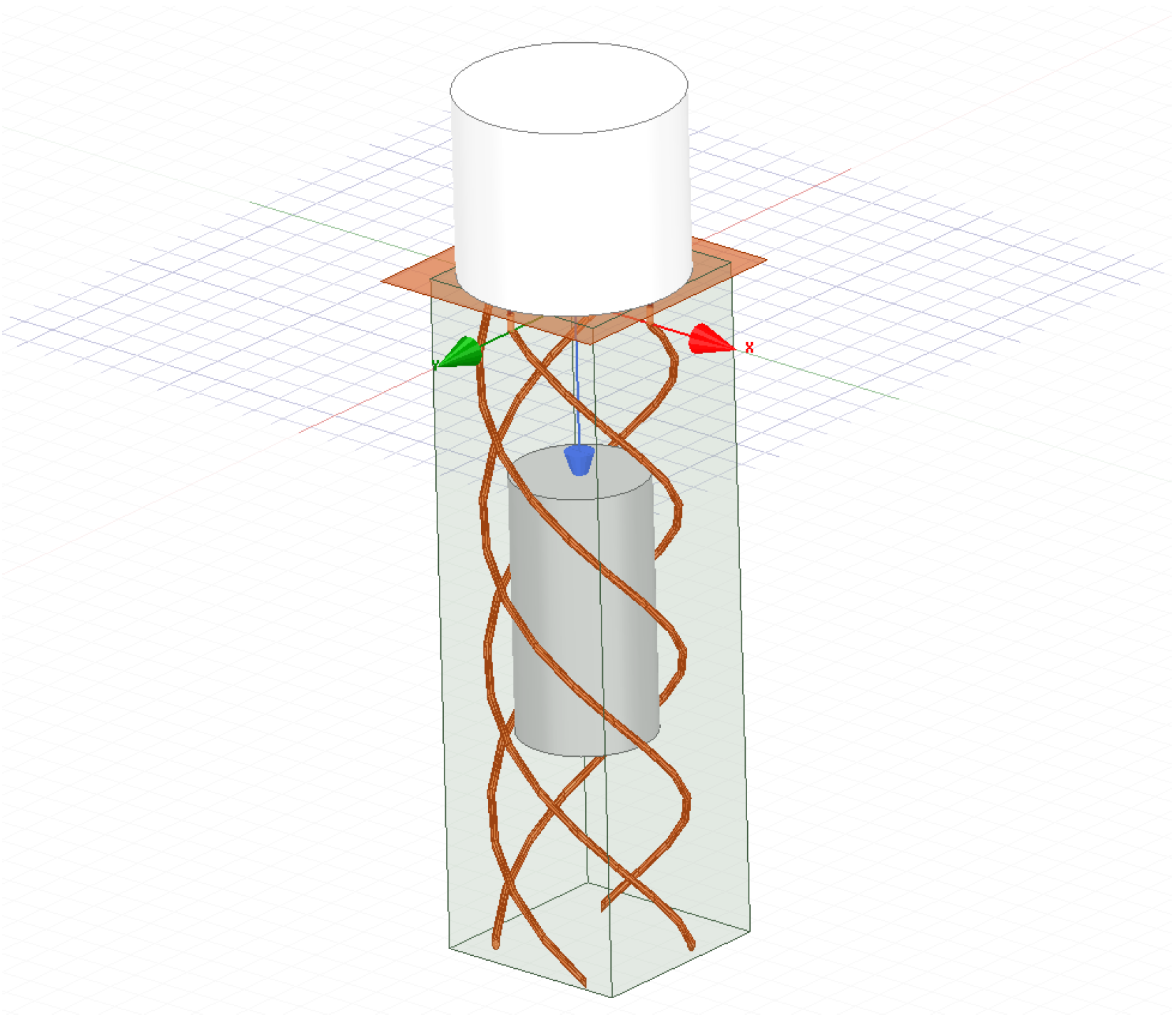
  • The height of the four-arm helical antenna is much higher than the length of the sonde, which results in a large amount of redundant space and a large volume of the entire drop system, which is contrary to the original design preferences of a small size, integrated design, and light weight. In view of the extremely limited space and weight requirements of the airship in the typhoon detection scenario, further optimization is needed to ensure the performance of the antenna while reducing the volume and weight.
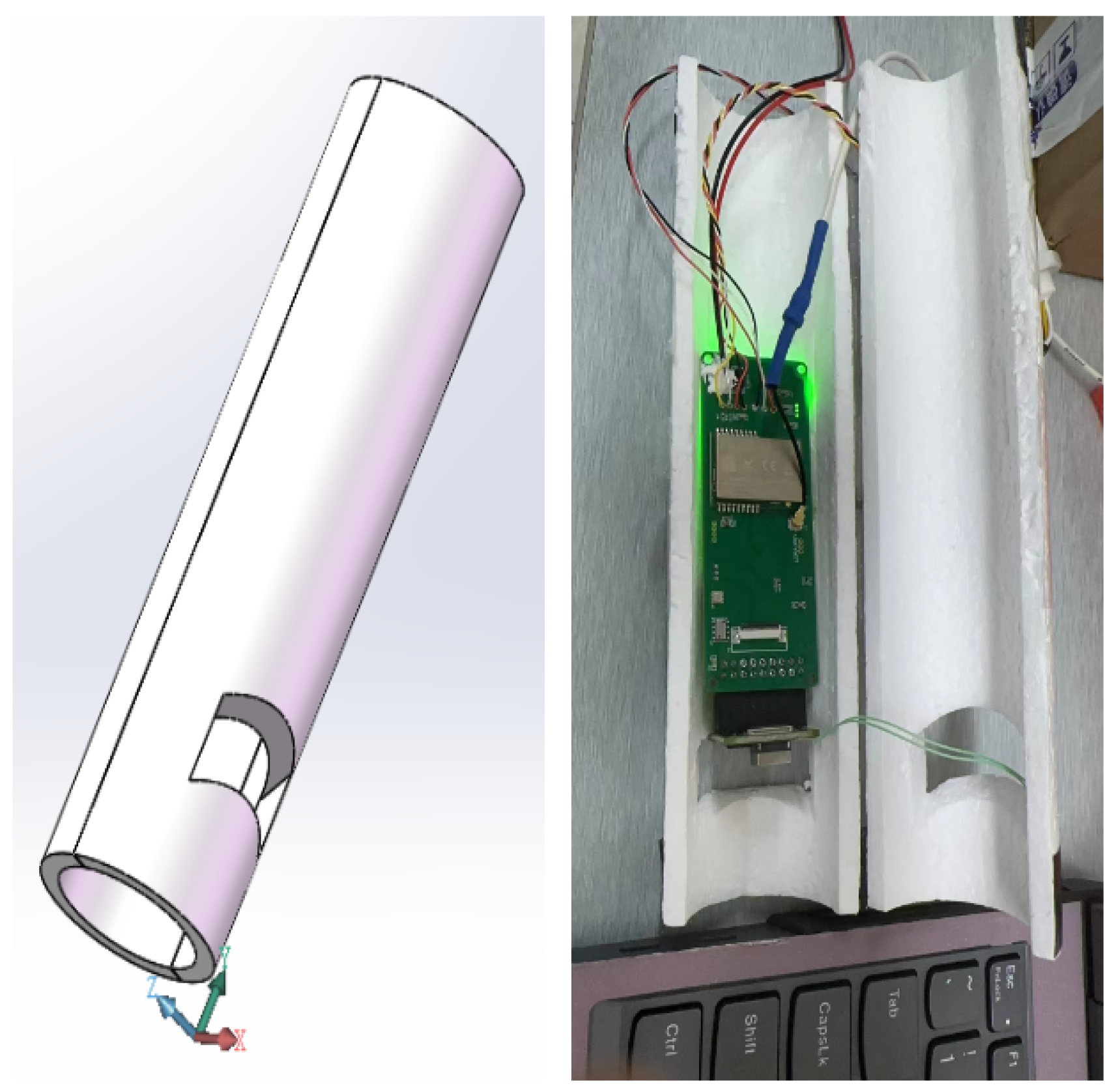
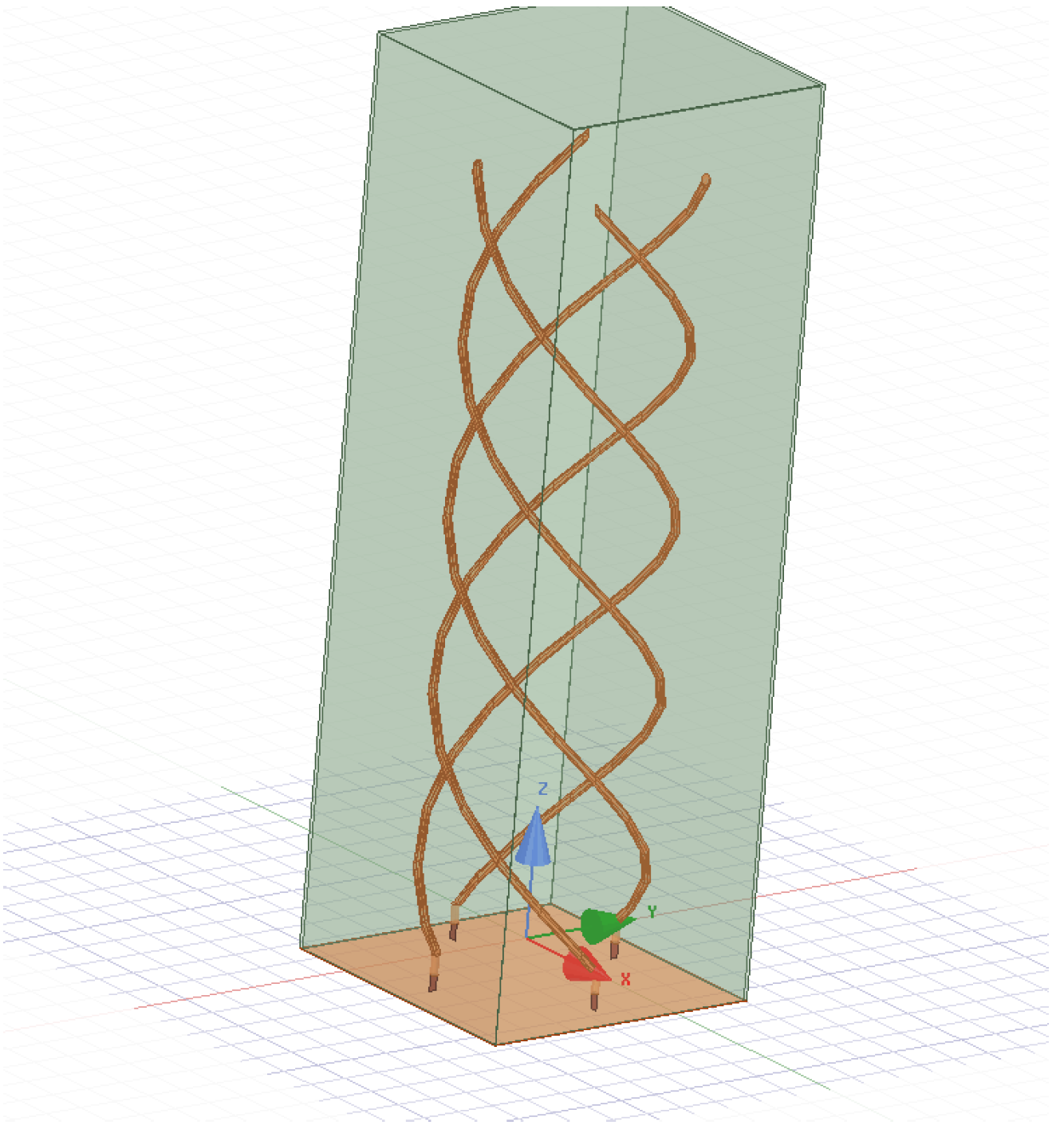
  • As shown in Figure 8, the four-arm helical antenna is in direct contact with the sounding instrument. During operation affected by high-altitude weather, the shaking sounding instrument can easily have a negative effect on the structural stability and performance of the four-arm helical antenna. If the antenna is subjected to external force impact and vibration from the sounding instrument, the antenna structure may be deformed or displaced, affecting the radiation performance of the antenna. Frequent collisions also accelerate the fatigue and damage of the antenna’s structure material, which may lead to the formation and expansion of microcracks. In severe cases, the antenna breaks and fails to function. These various mechanical noises also introduce interference signals, increase the noise level of the system, and affect the signal reception quality of the antenna.
Therefore, it is necessary to further reduce the size of the quadrifilar helical antenna while ensuring that the performance indicators meet the original design requirements. At the same time, it is imperative to ensure that the stability of the structure and performance of the quadrifilar helical antenna are not damaged by the radiosonde during operation. After consulting the literature, it was determined that the structure of the quadrifilar helical antenna can be printed with flexible materials, which has several advantages [18]. First, flexible materials are easy to process and can be conveniently used to produce complex antenna structures. Secondly, flexible materials can absorb mechanical stress and have better mechanical stability. In addition, they can still ensure RF performance under deformation conditions, solving some problems that may be caused by the collision between the radiosonde and the antenna. Thirdly, these flexible materials can further reduce the weight and size of our antenna, making it very suitable for the sensitive requirements of our typhoon detection project [19].
The flexible material can be made of PTFE (polytetrafluoroethylene) composite materials, such as the Rogers RT/duroid series. This type of material has low loss and a stable dielectric constant, making it very suitable for high-frequency antenna applications. RT/duroid 6002 was used in the simulation, and its dielectric constant is 2.94. In the original antenna scheme, the copper wire has high ductility and plasticity. Due to the large torque at the feeding point of the spiral antenna, it can be slowly deformed with ease via the impact of the radiosonde after long-term use. The PTFE tube has high hardness and deformation resistance and can withstand certain impacts in harsh weather environments without deformation. At the same time, it ensures the light weight of the antenna and heat preservation during the storage of the radiosonde.
In summary, the use of flexible materials meets the improvement requirements. The overall schematic diagram of the sounding system after improvement is shown in Figure 12.

4.1. HFSS Simulation Results

Therefore, the simulation was re-run with HFSS, and the previous scheme was replaced with a dielectric-loaded printed antenna. The modeled four-armed helical antenna was swept and simulated. The antenna simulation focused on a few results, namely the return loss, voltage standing-wave ratio, antenna directional maps, and axial ratio, as shown in Figure 13, Figure 14, Figure 15 and Figure 16, respectively.
Analyzing the simulation results and observing Figure 13, Figure 14, Figure 15 and Figure 16, it can be seen that the resonance frequency is near 403 MHz; the return loss reaches −17.9 dB at 403 MHz; and the voltage VSWR is 1.29, which is less than 1.5. The maximum gain of the antenna’s directional map reaches 6.3 dB, and it can reach a gain effect in all directions and meet the requirements of the cardioid directional map. Therefore, the performance indicators meet the requirements for use. The antenna’s axial ratio is less than or equal to 3 dB, so it is a good circularly polarized antenna in the main direction. The ECC between the antenna ports is 0.007361 between 1 and 2, 0.026491 between 2 and 3, 0.006164 between 3 and 4, and 0.000762 between 4 and 1, so the coupling between the antenna elements is low. The dimensions of the antenna are reported as follows. The height of the spiral arm in the vertical direction is L z = 22.7 cm, which is shortened by about 12 cm compared with the previous one; the radius of the spiral is r = 3.2 cm, corresponding to a reduction by about 2 cm compared with the previous one; and the volume is obviously smaller. The overall schematic diagram is presented in Figure 12, which shows that printing the four-arm spiral antenna with flexible material on the outside can avoid direct contact with space probes and improve the stability of the antenna’s structure and performance.

4.2. Comparison with Existing Antennas

One solution currently available on the market is InterMet’s iMet-3050A portable antenna, which is also a helical antenna that works in the 403 MHz frequency band and can perform environmental detection. However, it is not very suitable for lightweight typhoon detection scenarios. It has a gain of 2 dB, weighs 2.2 kg, and is 35 cm long. The results of the present study exhibit not only the reduced length and volume of the antenna but also an increase in gain of 4 dB, making our sensor more suitable for typhoon detection environments.
Other typhoon receiving antennas have been developed in recent years; for example, Liu et al. proposed a compact conformal helical antenna designed for typhoon detection that features a good axial ratio and wide bandwidth characteristics [20]. Similarly, Gu, X. et al. developed another antenna designed for environmental sensing, emphasizing lightweight construction to enhance reliability [21]. However, despite their superior axial ratios and other parameters, these antennas cannot be effectively deployed as droppable mechanisms in typhoon detection scenarios due to their complex structures, large dimensions, and weight constraints.
Compared to existing typhoon detection solutions and the typical application scenarios of quadrifilar helical antennas, our innovation lies in the following aspects. First, through mechanical structure design, we achieved maximum space utilization, using the quadrifilar helical antenna as a droppable device, thereby providing space for the radiosonde. Secondly, for airship detection scenarios, we reduced the device’s weight, achieving better integration, miniaturization, and lightweight design. Thirdly, flexible materials were chosen to ensure that the antenna can still operate stably in harsh typhoon environments.

5. Conclusions

In a traditional droppable detection system, the receiving antenna, the droppable release device, and the sounders are usually placed separately in the airship. However, the utilization of space was improved in this study by employing a four-armed helical antenna as the receiving antenna and as the inner wall of the droppable release device at the same time. However, when the antenna is directly used as the inner wall, the airflow at high altitude causes the sounder to be in direct contact with the inner wall, which may damage the structure and stability of the antenna. Therefore, direct contact with the sounder is avoided by printing the four-armed helical antenna on top of the medium as the outer wall using flexible materials, allowing the weight of the device to be further reduced. The designed antenna was modeled with HFSS, and the modeled four-armed helical antenna was set up for frequency sweeping and simulation. The resonance frequency of the antenna is around 403 MHz and reaches −17.9 dB at 403 MHz. The voltage VSWR is 1.29, which is less than 1.5. The maximum gain of the antenna reaches 6.3 dB, and it can achieve a gain effect in all directions. The antenna meets the requirement of the cardioid directional graph and can reach the performance index set in this study after researching antennas commonly used and available on the market.

Author Contributions

Software, Y.L.; Writing—review & editing, Z.L. and T.L.; Supervision, T.H. All authors have read and agreed to the published version of the manuscript.

Funding

The work by Tao Hong is supported by the National Natural Science Foundation of China under Grant Nos. 61827901 and 3F72F5D9.

Institutional Review Board Statement

Not applicable.

Informed Consent Statement

Not applicable.

Data Availability Statement

The original contributions presented in the study are included in the article, further inquiries can be directed to the corresponding author.

Conflicts of Interest

The authors declare no conflicts of interest.

References

  1. Li, Z.; Shen, L. The Development History of Conventional Radiosonde Instruments in New China—Interview with Engineer Li Jiming. Chin. J. Hist. Sci. Technol. 2023, 44, 143–153. [Google Scholar]
  2. Peng, W.; Huang, X.; Zhang, Y.; Guo, Z.; Yang, S.; Zheng, H.; Hu, J.; Chen, W.; Bai, B.; Jiang, Y. Drop-Sonde and Its Deployment Method and System. CN110927826A, 31 August 2024. [Google Scholar]
  3. Liu, D.; Feng, J.; Ding, R.; Li, J. Review of Progress in Typhoon Target Observation. Adv. Earth Sci. 2021, 36, 15. [Google Scholar] [CrossRef]
  4. Ma, S.; Zhao, Z.; Xing, Y. VAISALA Radiosonde Technology and the Development of Radiosonde Technology in China. Adv. Meteorol. Sci. Technol. 2005, 33, 4. [Google Scholar]
  5. Mackle, C. Vaisala Ranks in Top Five Climate Leaders 2022 List. Condition Monitor 2022, TN.422. Available online: https://www.vaisala.com/en/press-releases/2022-04/vaisala-ranks-top-5-financial-times-climate-leaders-2022-list (accessed on 26 August 2024).
  6. Wang, Y.; Wang, G.; Lin, J.; Lu, S.; Guan, S. Progress in Marine Observations of Tropical Cyclones. Adv. Mar. Sci. 2023, 41, 23. [Google Scholar]
  7. Tang, J.; Zhao, B.; Lei, X. Progress and Prospects of Domestic and International Typhoon Flight Science Experiments. Adv. Meteorol. Sci. Technol. 2022, 12, 47–55. [Google Scholar]
  8. Wang, Y.; Tu, M.; Miao, M.; Yang, S. Application of Beidou Satellite Navigation System in Meteorology. Satell. Appl. 2023, 10, 42–48. [Google Scholar]
  9. Liu, W.; Zhang, M.; Qu, X.; Jin, Y. Significant Advances in China’s Satellite Applications in 2023. Satell. Appl. 2024, 1, 6–14. [Google Scholar]
  10. Hu, M. The First Beidou Radiosonde Observation System in the Province is Built and Entered the Debugging Stage in Pu’er. Yunnan Daily. 15 April 2024. Available online: https://yndaily.yunnan.cn/content/202404/15/content_198440.html (accessed on 26 August 2024).
  11. Xu, R. Research on Broadband and Multiband Circularly Polarized Antennas. Master’s Thesis, Northwestern Polytechnical University, Xi’an, China, 2 January 2018. [Google Scholar]
  12. Luo, W. A Novel Design of Ultra-Wideband Planar Equiangular Spiral Antenna. Commun. Technol. 2013, 6, 12–14. [Google Scholar]
  13. Letestu, Y.; Sharaiha, A. Broadband Folded Printed Quadrifilar Helix Antenna. IEEE Trans. Antennas Propag. 2006, 54, 1600–1604. [Google Scholar] [CrossRef]
  14. Ning, B. Research on GNSS Broadband Quadrifilar Helix Antenna. Master’s Thesis, Xidian University, Xi’an, China, 2014. [Google Scholar]
  15. Peng, C. Research on Integrated Shark Fin Antenna for Vehicle Networks. Master’s Thesis, Shanghai Jiao Tong University, Shanghai, China, 2020. [Google Scholar]
  16. Wang, H. Design of Miniaturized Broadband Quadrifilar Helix Satellite Navigation Receiving Antenna. Master’s Thesis, Xi’an University of Technology, Xi’an, China, 2020. [Google Scholar]
  17. Kilgus, C. Shaped-Conical Radiation Pattern Performance of the Backfire Quadrifilar Helix. IEEE Trans. Antennas Propag. 1975, 23, 392–397. [Google Scholar] [CrossRef]
  18. Xiao, C.; Shi, X.; Li, P.; Guo, C. Broadband and Wide-Beam Inverted Conical Printed Quadrifilar Helix Antenna. In Proceedings of the National Microwave Millimeter Wave Conference, Ningbo, China, 1 October 2007; Chinese Institute of Electronics: Beijing, China, 2007. [Google Scholar]
  19. Gao, Y. Research on Miniaturized Dielectric-Loaded Quadrifilar Helix Antenna in Global Positioning System. Master’s Thesis, Zhejiang University, Hangzhou, China, 2008. [Google Scholar]
  20. Chang, L.; Chen, L.-L.; Chen, Z.-Z.; Zhang, J.-Q. A Compact Wideband Four-Arm Spiral Antenna with Dual Modes. Microw. Opt. Technol. Lett. 2021, 63, 1243–1248. [Google Scholar] [CrossRef]
  21. Gu, X.; Zhao, J.; Duan, H.; Liu, Y.; Peng, Y. A Controllable Multifunctional Four-Arm Helical Antenna Array. In Proceedings of the 2024 9th International Conference on Computer and Communication Systems (ICCCS), Xi’an, China, 19–22 April 2024; pp. 1078–1082. [Google Scholar] [CrossRef]
Figure 1. Schematic representation of airship sounding (color).
Applsci 14 07956 g001
Figure 2. Outline and internal structure of the sounder.
Applsci 14 07956 g002
Figure 3. Schematic diagram of a four-armed helical antenna.
Applsci 14 07956 g003
Figure 4. Decomposition schematic of the structure of the four-armed helical antenna.
Applsci 14 07956 g004
Figure 5. Decomposition schematic of the structure of the four-armed helical antenna.
Applsci 14 07956 g005
Figure 6. Equivalent model of four-armed helical antenna.
Applsci 14 07956 g006
Figure 7. HFSS modeling of the completed four-armed helical antenna.
Applsci 14 07956 g007
Figure 8. Return loss.
Applsci 14 07956 g008
Figure 9. Voltage VSWR.
Applsci 14 07956 g009
Figure 10. Radiation pattern.
Applsci 14 07956 g010
Figure 11. Overall schematic diagram of the droppable sounding system.
Applsci 14 07956 g011
Figure 12. Overall schematic of the improved droppable sounding system.
Applsci 14 07956 g012
Figure 13. Return loss.
Applsci 14 07956 g013
Figure 14. Voltage VSWR.
Applsci 14 07956 g014
Figure 15. Radiation pattern.
Applsci 14 07956 g015
Figure 16. Axial ratio.
Applsci 14 07956 g016
Disclaimer/Publisher’s Note: The statements, opinions and data contained in all publications are solely those of the individual author(s) and contributor(s) and not of MDPI and/or the editor(s). MDPI and/or the editor(s) disclaim responsibility for any injury to people or property resulting from any ideas, methods, instructions or products referred to in the content.

