Article

Key Parameters of the Roof Cutting and Pressure Relief Technology in the Pre-Splitting Blasting of a Hard Roof in Guqiao Coal Mine

1
College of Safety and Engineering, Anhui University of Science and Technology, Huainan 232001, China
2
Key Laboratory of the Ministry of Education Jointly Established by the Provincial and Ministerial and Ministerial Departments for Safe and Efficient Mining of Coal Mines, Anhui University of Science and Technology, Huainan 232001, China
*
Author to whom correspondence should be addressed.
Appl. Sci. 2024, 14(24), 11779; https://doi.org/10.3390/app142411779
Submission received: 7 November 2024 / Revised: 10 December 2024 / Accepted: 12 December 2024 / Published: 17 December 2024
(This article belongs to the Special Issue Advances and Challenges in Rock Mechanics and Rock Engineering)

Abstract

:
The phenomenon of crushing the support of the hard roof of a coal seam occurs occasionally during the coal mining process. However, making the hard roof fall is difficult due to its good integrity and high strength. A vast area of unsupported, suspended roof can easily form in the goaf, inducing the hidden dangers of rock burst and coal and gas outbursts. A deep-hole pre-splitting blasting technique is used to fracture the roof and relieve the pressure exerted by the rigid roof in order to improve the caving of the hard roof and protect the stability of the roadway, ensuring safe and effective operational production of the 1127 (1) working face in Guqiao Coal Mine. By collecting field samples, the mechanical properties of relevant rock formations are ascertained. Combining numerical simulation with theoretical computation, a roof cutting pressure-relief scheme with a roof cutting height of 13.5 m and a roof cutting angle of 20° is selected. This scheme can decrease the peak vertical stress on the roadway roof from 22.01 MPa to 13.63 MPa compared to when roof cutting is not performed. By ensuring the effectiveness of roof cutting for pressure relief, this scheme can optimize the actual construction workload to a minimum. The study’s conclusions provide insightful information and can be used as a guide for future research on related technical topics.

1. Introduction

The most crucial prerequisite for safe and effective mining in coal mines is making sure the mining roadway is stable. Coal pillars are typically left in place to safeguard mining roadways next to the working face while coal resources are being recovered. Coal pillars, which are usually 15 to 25 m long and waste a significant amount of coal resources, are used to enhance the stress environment within the roadway since it is subject to residual lateral support stress. Both the lateral bearing stress value and its influence range intensify further as the working face’s mining depth gradually rises. Consequently, when the breadth of the coal pillar designated for safeguarding the roadway needs to be expanded, the quantity of coal resources lost increases even more [1,2,3]. Within the range of the working face, the weak roof will collapse on its own under the action of mining stress. Meanwhile, the hard roof generally exhibits the characteristics of considerable layered thickness, high strength, good integrity, and strong self-stability, and thus, a substantial area of suspended, unsupported roof is probably going to form. Once the suspended roof collapses, a support crushing accident of the working face will occur, inducing disasters, such as impact airflow, rock burst, and coal and gas outbursts [4,5,6]. Many academics have studied roof cutting and pressure-relief technology in depth in the context of hard roof situations in recent years. By altering the continuity and integrity of hard roof strata, this method can lessen the extent to which mining can affect the working face. At present, the two main processes for cutting roofs and relieving pressure are hydraulic fracturing and pre-splitting blasting. From the perspective of this technology’s economy and practicability, the former exhibits the advantages of extensive applications, good effect, and low cost [7,8]. Zhu Z et al. chose the 8104 and 8105 working faces of Tongxin Coal Mine as their research subjects. After analyzing the stress behavior as the working face formed, they found that the hard roof construction negatively affected both the stress behavior and the stability of the coal pillar during mining operations [9]. Liu W et al. analyzed the dynamic mechanism underlying the instability of surrounding rock in entry on the gob-side. Their findings revealed that, in the presence of a hard roof, the maximum stress endured by the surrounding rock in the gob-side entry surpassed the original rock stress by a factor of ten. Furthermore, the high stress accumulation in the roadway’s surrounding rock posed a significant risk of triggering dynamic disasters [10]. Kong P et al. formulated an equation for the lateral support stress distribution near the working face’s end, both pre and post roof cutting. Their investigation focused on the characteristics of roadway deformation after roof cutting, as well as the plastic zone and stress distribution inside the stope. According to their research, roof cutting decreased the vertical stress at the mining face, accompanied by an expansion of the roof’s plastic zone, thereby ensuring the roadway remains stable [11]. The response mechanism and control strategy for a roadway around rock in a fully mechanized caving face were examined by Wang H et al., particularly under conditions of a hard roof. Their numerical simulations and real-world implementations showed that this technique significantly reduced the peak vertical stress, successfully cut the main roof’s overhang length, and lessened the damage and deformation of the nearby rock [12]. Huang X et al. examined the 3405 working face of Danyang Coal Mine. Through theoretical calculations and numerical simulations, they modeled how various roof cutting parameters affected the efficacy of roof cutting. Field testing also demonstrated that roof cutting reduced roadway deformation and the maximum stress that the supporting wall could withstand [13]. Hao Y et al. presented a control system that combined grouting cable anchor reinforcement, bolt reinforcement, and roof cutting and pressure release. The number of coal pillars needed was decreased as a result of this combination strategy’s successful management of the rock surrounding the roadway’s displacement and deformation [14]. Zhang K et al. used RocLab software (version 1.0) to determine the most effective roof cutting solution and then successfully applied it to Gaohe Coal Mine; peak roof settlement was considerably reduced [15]. A Mohr circle analysis model was created by Wang Y et al. to investigate the stress evolution process. By examining stress evolution, they unveiled the fundamental causes of roadway deformation and subsequently suggested pertinent control strategies [16]. In accordance with key block theory, a mechanical model of the basic roof’s fracture structure was made by Sun B et al., who also investigated the goaf side’s roof fracture process in situations including roof cutting and pressure release techniques [17]. He J et al. believed that the stress on the deep surrounding rock and the blasting effect are crucial factors contributing to rock bursts in deep mining areas; these factors are more important for controlling a hard roof [18]. Gao F et al. investigated the temporal system of roof-induced caving during continuous mining operations beneath a complex filling structure. In accordance with similarity theory, the data system was used to automatically collect and analyze stress and displacement changes with mining progress [19]. Hu J et al. proposed an induced roof caving method, in which a certain grasp of the space–time position of the induced roof caving was obtained. A variety of influencing factors of induced roof caving in goaf were studied using catastrophe theory [20]. Guo X et al. developed a mechanical model to elucidate the relationship between bolt tensioning and the anchoring interface, established the axial force equation of the bolt drawing and anchoring interface, determined the shear stress distribution and load decreasing the law governing the transfer of force within the bolt anchoring section, and achieved successful management of the nearby rock in the hard roof area [21]. Ma X et al. studied and calculated the roof cutting parameters and seam connectivity rate of inclined coal seams; they advanced research on roof cutting and pressure relief technology by introducing the idea and design process of the roof cutting connectivity rate [22]. After conducting a comprehensive analysis that took into account the economic feasibility and safety concerns related to the roof and floor of the roadway, the deep-hole pre-splitting blasting method was adopted to perform hard roof cutting and implement pressure-relief measures, ensuring efficient and safe mining operations in the hard roof area of the fully mechanized 1127 (1) working face at Guqiao Coal Mine. The following results were achieved: the tendency of the hard roof to cave was enhanced, enabling timely roof fall. This reduction in roof pressure mitigated its impact on the working face support, thereby ensuring roadway stability and facilitating smooth mining operations.

2. Engineering Background

The 1127 (1) working face of Guqiao Coal Mine is situated in the north downhill mining area, north of the F87 fault, south of the 11-2 coal seam system roadway in the north mining area, and east of the 1127 (1) transport roadway. The minimum net stack is 8 m. The roof comprises thick layers of fine and medium sandstone. The layout of the working face is illustrated in Figure 1, while its geological column is depicted in Figure 2.
In accordance with the measured data of 1126 (1)’s transport cross heading and the analysis of the drilling data of 1127 (1)’s transport cross heading floor roadway, working face, and nearby drilling data, the occurrence of the 11-2 coal seam in 1127 (1)’s working face is relatively stable, black, mostly massive, and locally powdered. The coal–rock group is largely composed of bright and dark coals, asphalt with weak luster, semi-bright coals, stepped fractures, black-brown stripes, and one layer of mudstone with gangue. The 1127 (1) working face exposes the 11-2 coal seam, which has an estimated thickness ranging from 2.10 to 5.12 m, averaging 3.10 m, and experiences significant fault variations. Table 1 lists the precise dimensions of this coal seam’s floor and roof.

3. Pressure Relief Mechanism of Roof Cutting

The roof management of an ordinary coal mining face generally goes through three stages. When the working face is excavated during the first stage of mining, the immediate roof first collapses and a section of the hanging roof forms. In the second stage, as mining progresses, the main roof experiences increased pressure, i.e., it breaks or sinks, and the goaf is gradually filled. In the third stage, the working face progresses further, the main roof bends and sinks, and the goaf forms a stable structure. In the first stage, similar to the second stage of the development process, the hanging roof is formed in the goaf. The emergence of this type of hanging roof has two effects. On the one hand, the contact stress between the direct roof and the old roof is significantly reduced. The contact layer can easily slip between the layers because of the uncoordinated deformation, and, thus, shear failure occurs in the roadway near the working face. On the other hand, in addition to increasing roof sinking close to the roadway’s goaf side, the suspended roof places a significant additional pressure on the highway support system, which encourages separation between the immediate roof and the main roof. The support load in the road adjacent to the working face rises dramatically as a result of the pressure from the rock layers that cover it and the rotating deformation of the hanging roof beam. If the support resistance of the roadway is low, then it will produce a large deformation and even cause a collapse or roof fall, and, thus, the working face requires an upgrade to its forward support system.
The mechanical concepts discussed above are expanded upon in the research on roof cutting and pressure-relief technologies at the working face. The hard roof will collapse along the pre-established splitting surface as a result of mining-induced stresses, the roadway roof will be able to form a cutting surface along the roof cutting line, the surrounding rock’s stress distribution will be changed, and an effective gangue support structure will be built in the goaf area to regulate the movement of the overlaying rock formations; additionally, roof cutting boreholes will be drilled, either small-spaced or two-way energy-gathering tension blasting. Through the use of roof cutting and pressure-relief technologies, the overlaying strata’s effects on the surrounding rock of the mining route are lessened, improving the stress conditions and rock stability. In the end, this approach achieves the goals of pressure alleviation and roof cutting.

3.1. Key Parameters of Roof Cutting Design

The fundamental idea behind pressure relief roadway protection and roof cutting is to allow the cut roof to fill the goaf as soon as is feasible, such that the rock mass structure formed by the main roof fracture can immediately come into contact with the gangue. Therefore, for roof cutting and pressure-relief technologies to be implemented successfully, it is essential to precisely identify the essential technical parameters. The height and angle of roof cutting are the primary determinants of the impact of pressure-relief technology and roof cutting.

3.1.1. Cutting Top Height

The weak surface within the rock mass structure is artificially constructed via blasting roof cutting, which raises the roof’s caving height and interferes with the roof strata’s method of failure. The design of the roof cutting height mainly considers the need to fill the goaf after the roof has expanded and caved in order to provide an efficient support structure for the goaf area’s roof and reduce the effect of the high roof’s rotational subsidence on the stability of the surrounding rock of the roadway. Additionally, the roof strata structure, which encourages roof caving after cutting, is taken into consideration. The roof cutting height is defined as the vertical distance between the bottom of the blasting hole and the horizontal plane. The roof cutting height, HF, is calculated using Equation (1) based on the lithological features of the roof at the 1127 (1) working face in Guqiao Coal Mine:
H F = H M H 1 H 2 k 1 ,
where H M is the thickness of the coal seam, m; H 1 is the roof subsidence, m; H 2 is the amount of floor heave, m; and k is the bulking coefficient, which is typically 1.3–1.5.
Inputting the engineering geological conditions of Guqiao Coal Mine into the formula, the average thickness of the coal seam in the 1127 (1) working face H M is 3.1 m, the average thickness of the immediate roof is 4.5 m, the average thickness of main roof is 9.0 m, and the average expansion coefficient k of the rock stratum is 1.3. In the calculation,
H F = H M H 1 H 2 k 1 = 10.3   m < i = 1 n H i = 13.5   m .
After substituting the parameters into the formula, the calculated roof cutting height is about 10.3 m. If the height of the roof cutting is less than the total thickness of the main roof and the immediate roof, then the roof cutting can easily become incomplete, and, thus, the correlation of the roof strata cannot be destroyed completely, impacting the efficiency of the pressure-relieving and roof cutting technologies. Therefore, the roof cutting height of pre-splitting blasting should be at least 13.5 m of the combined thickness of the main roof and the immediate roof.

3.1.2. Cutting Angle

The roof cutting angle design should lessen the friction impact on the roadway’s roof during the collapse of the gob area’s roof in order to position the roadway as far away as possible and in a low-stress area to improve the implementation of roadway protection. The roof cutting angle, θ, is defined as the angle formed between the roof cutting line and the vertical line. During the advancement of the working face, the basic roof, after reaching its ultimate suspension length, breaks into rock blocks. A sturdy voussoir beam structure is created by the interaction and compression of these broken pieces. The blasting cut surface acts as the biting surface for the broken blocks when the pre-splitting blasting method is used for pressure relief and roof cutting. The force analysis at the biting points of the key blocks is illustrated in Figure 3.
The fundamental requirement for the instability and possible slippage of the key block, as determined by the voussoir beam theory and the S-R stability principle governing the surrounding rock structure, is
( T cos θ R sin θ ) tan φ R cos θ + T sin θ ,
θ φ a r c t a n R T .
Substituting T = q L 2 2 ( h s ) and R = qL into Equation (4), we have
θ φ a r c t a n 2 ( h s ) L ,
where θ is the roof cutting angle, °; T is the horizontal compressive force between the rock blocks, kN; R is the shear force at the contact of the rock mass, kN; q is the intensity of the basic roof load of the working face, kN/m; L is the length of the basic roof fractured block, 19.8 m; h is the thickness of the fine sandstone layer in the basic roof, 7 m; Δs is the subsidence of the fractured rock block, 3.9 m; and φ is the internal friction angle of the fine sandstone, 31°. After calculation, it is concluded that θ ≥ 13.6°.

4. Numerical Simulation

4.1. Model Establishment

Considering the geology and actual mining conditions of the 1127 (1) working face in Guqiao Coal Mine, a 3D numerical model was created using FLAC3D software (version 6.0) for numerical simulation in order to verify the control effect of the roof cutting and pressure relief technology. In accordance with the calculation results, the vertical stress variation law around the roadway before and after roof cutting was compared and analyzed. A model with a length × width × height of 300 m × 30 m × 40 m was established, and it was divided into approximately 1,700,000 grid elements. The coal seam had an average burial depth of approximately 780 m, with its upper border subjected to an initial vertical stress of 19 MPa. The size of the roadway was 4 m × 3 m, and the upper portion of the goaf side of the roadway was where the pre-splitting roof cutting line was placed. To fully reflect the strength characteristics of rock, the failure of rock in this calculation was determined using the Mohr–Coulomb yield criterion. The mechanical parameters of the main coal and rock strata were considered in accordance with the mechanical test results and related geological data, as shown in Table 2.

4.2. Analysis of Roof Cutting Effect

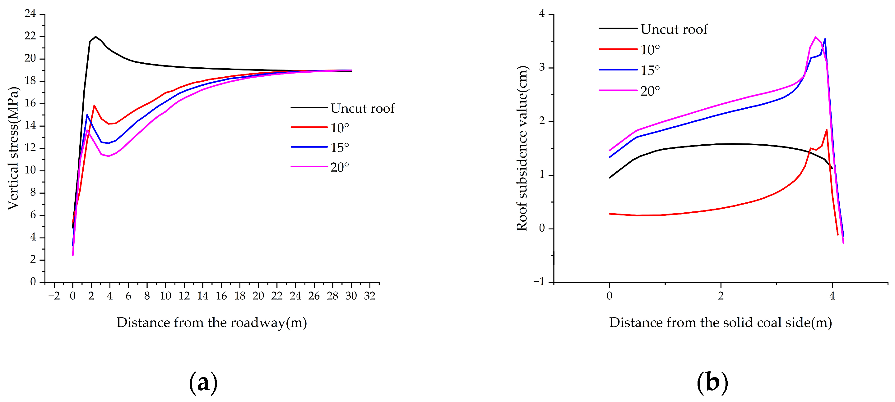
The numerical simulation is computed using the control variable method. First, the roof cutting angle is determined. The angle is used as a variable to analyze the stress evolution features associated with different roof cutting angles. A roof cutting height of 13.5 m can guarantee that the coal seams overlying the main roof strata are totally cut off in this section of the calculation, which is based on a thorough analysis that combines theoretical calculations and engineering practices. It also makes it possible to clearly observe how the roof cutting angle affects the strata’s stress-evolution characteristics. Four types of roof cutting schemes, namely, no roof cutting and roof cutting angles of 10°, 15°, and 20°, are implemented, and the stress changes in the surrounding rock of the roadway are compared and analyzed. Figure 4 displays the vertical stress distribution of the rock around the roadway at various roof cutting angles, while Figure 5a displays the vertical stress curve. Without a cut roof, concentration of vertical stress occurs on both sides of the roadway, resulting in floor heaving and roof sagging, putting the roadway in a high-stress situation. This situation can easily lead to deformation of the roadway’s surrounding rock. The analysis of the vertical stress variation on the right-hand side of the roadway is the main emphasis of this work. The displacement and vertical stress curves show that vertical stress rises quickly with distance, reaching a maximum of 22.01 MPa at 2.45 m from the roadway. As the distance increases, the vertical stress gradually returns to the original rock stress levels.
After the roof is cut, the pre-splitting blasting, roof cutting, and pressure-relief effects are clearly visible because the peak vertical stress is noticeably lower than when the roof is left uncut. When the angle is set to 10°, the vertical stress peak is reached at 2.31 m away from the roadway and is reduced to 15.85 MPa, which is about 28% lower than that without roof cutting. With an increase in distance, vertical stress gradually decreases until it reaches the lowest value at 3.85 m away from the roadway, i.e., about 14.20 MPa. The vertical stress peak is 1.54 m from the roadway and is roughly 15.00 MPa when the angle is 15°. This is about 32% less than the stress peak without roof cutting. The vertical stress peak further diminishes as the roof cutting angle increases. As distance increases, vertical stress decreases, and the minimum stress is 12.47 MPa. Then, vertical stress gradually increases and returns to the original rock stress. When the angle is 20°, the vertical stress peak is 13.63 MPa and 1.67 m from the roadway. This is roughly 38% less than the vertical stress peak when the roof is left uncut. Vertical stress drops to 11.30 MPa with increasing distance. A study of the three roof cutting angle schemes’ impacts on pressure relief and roof cutting shows that a 20° angle produces the best roof cutting and the largest decrease in the vertical stress peak.
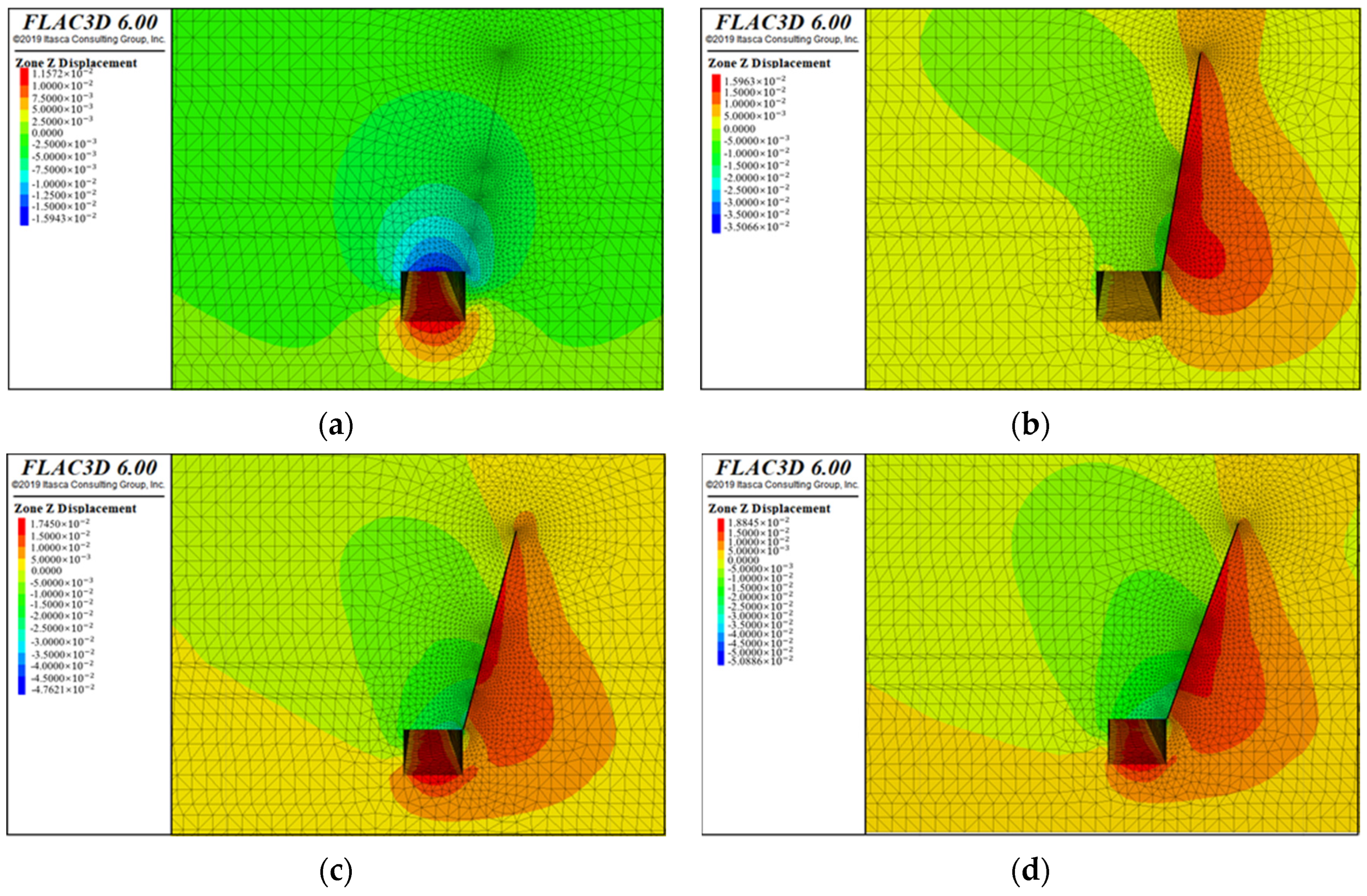
Figure 6 shows the vertical displacement of the roadway surrounding rock with different roof cutting angles, and Figure 5b shows the vertical displacement curve. From the perspective of roadway roof displacement, in the absence of roof cutting, both roof subsidence and floor heave are observed. The largest roof subsidence occurs in the center of the roadway, sinking to about 1.58 cm. When the angle is 10°, the subsidence of the roadway roof near the kerf side gradually increases, and peak displacement is 1.85 cm. When the roof is cut at an angle of 15°, the roadway’s roof sinking rises, and peak displacement is 3.54 cm. When the roof is 20°, the peak displacement of roof subsidence is 3.58 cm, which does not considerably differ from that of 15°. Combining the theoretical calculation results, numerical simulation results, and engineering practice, a conclusion is drawn that the cutting angle scheme is 20°.
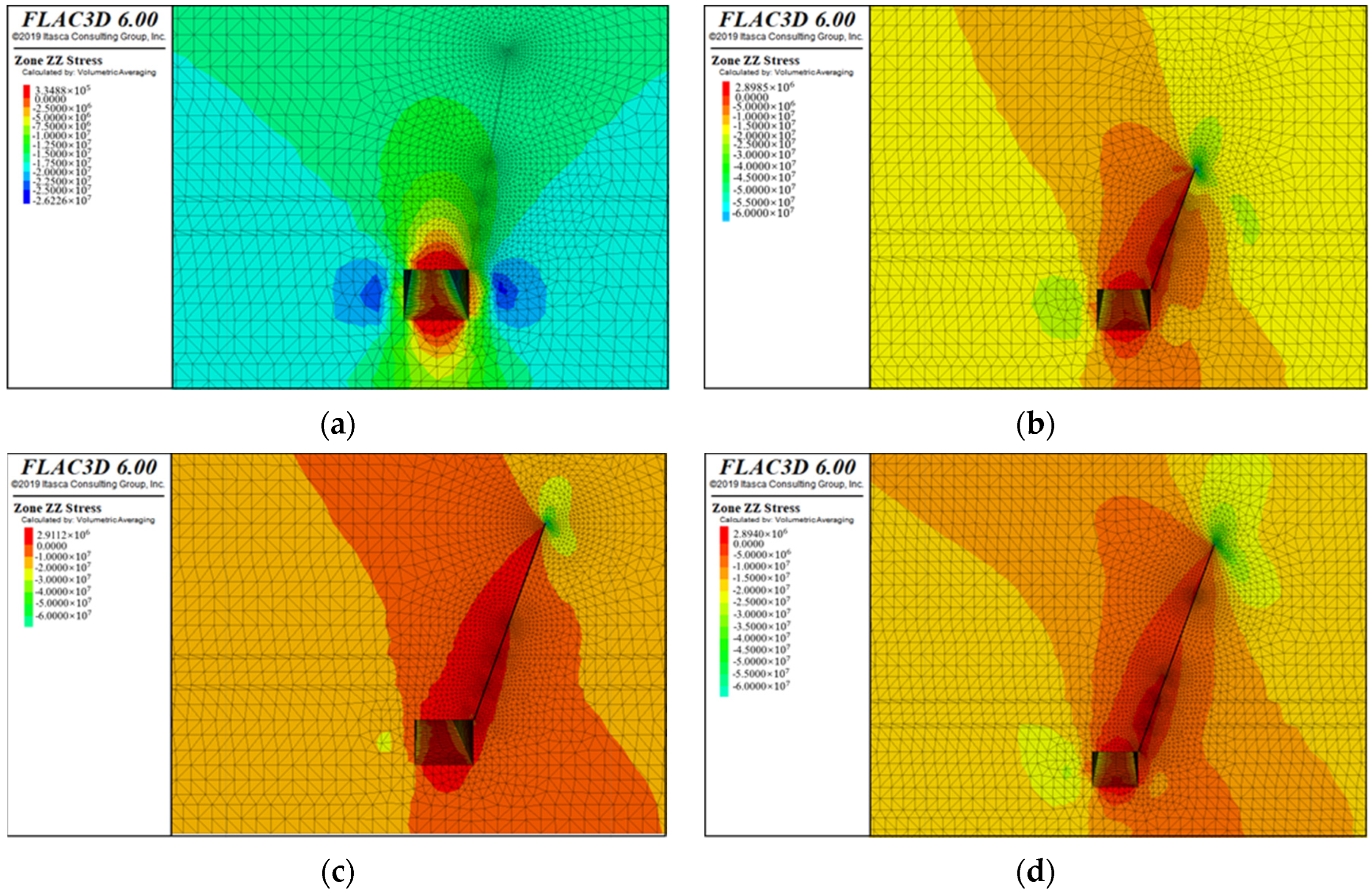
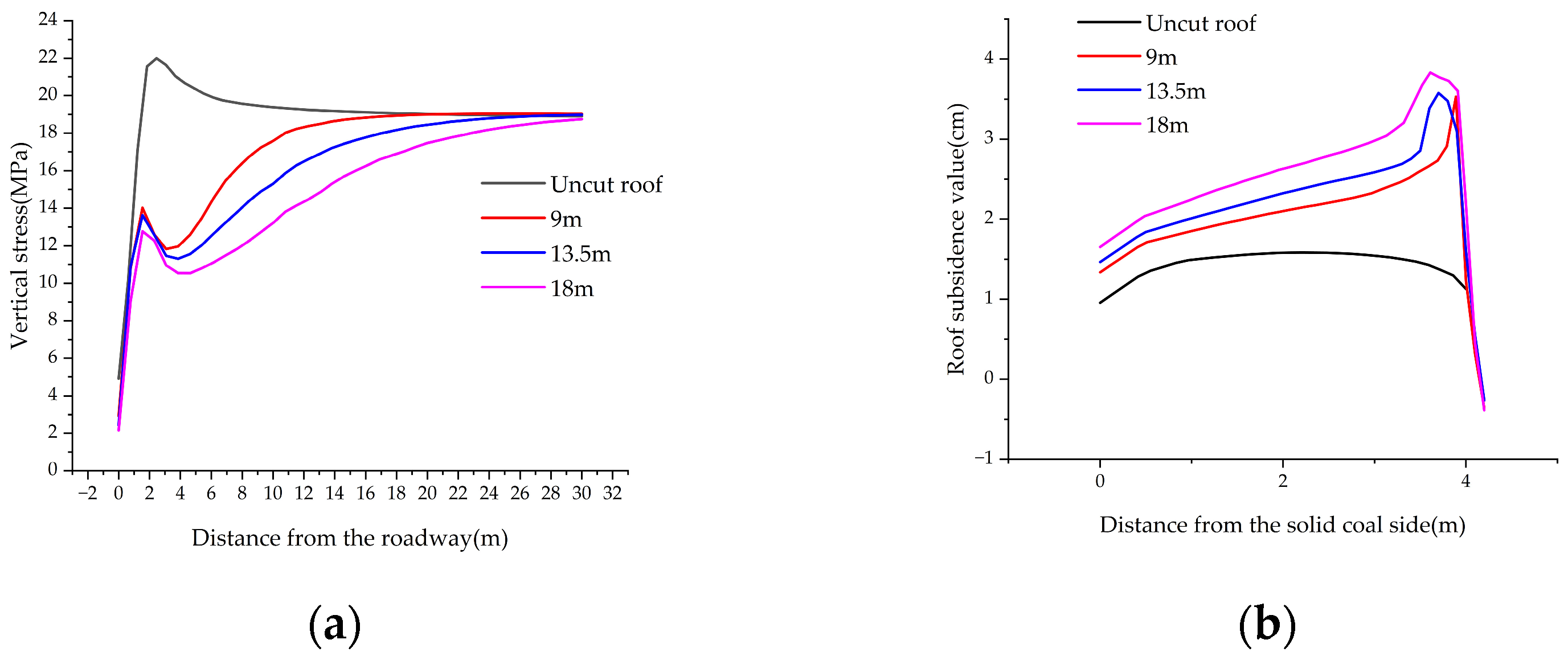
The cutting height is then established. Figure 7 shows the vertical stress distribution in the rock surrounding the roadway for various roof cutting angles, and the vertical stress curve is depicted in Figure 8a. Based on the aforementioned theoretical calculations and simulation outcomes, the cutting angle for this section is determined to be 20°, and four schemes, namely, uncut roof and cutting heights of 9, 13.5, and 18 m, are implemented. When the vertical stress variations in the rock around the roadway are compared and analyzed, it can be shown that the highest vertical stress, without roof cutting, is 22.01 MPa. Following roof cutting, the peak vertical stress significantly decreases, as seen by the vertical stress curve. The vertical stress peak, which is 1.54 m from the roadway, is lowered to 14.02 MPa when the roof cutting height is 9 m. This is roughly 36% less than when the roof is left uncut. When the cutting height is 13.5 m, the vertical stress peak is further reduced to 13.63 MPa, which is approximately 38% lower. When cutting height is 18 m, the vertical stress peak is reduced to 12.77 MPa, which is about 42% lower. The vertical stress peak under the three distinct roof cutting heights stays comparatively steady, according to the vertical stress curve generated from the numerical simulation data, with a fluctuation range of less than 1.5 MPa. Therefore, analyzing and considering the actual construction amount and the roof rock structure are necessary. When the cutting height reaches 9 m, the roof cutting seam remains confined within the basic roof area of the rock layer. Consequently, this scenario fails to effectively disrupt the integrity of the hard rock layer, resulting in a suboptimal pressure relief effect. Improving the roadway’s overall stability is difficult and could possibly cause stress concentration in the roof rock layer, which could lead to catastrophic dynamic disasters. The cutting seam penetrates deeply into the main roof at a height of 18 m, the real construction amount is excessive, and the enhancement of the roof cutting pressure relief effect is not noticeable, which can easily result in resource waste.
Figure 9 shows the vertical displacement curve of the roadway surrounding rock with different roof cutting angles, and Figure 8b shows the vertical displacement curve. From the standpoint of roadway roof displacement, when the cutting height is 9 m, the subsidence of the roadway roof near the cutting side increases, and peak displacement is 3.53 cm. When the roof is cut at a height of 13.5 m, the peak displacement of the roadway roof rises to 3.57 cm. At a cutting height of 18 m, the peak displacement of the roadway roof further increases to 3.83 cm. Considering the theoretical calculation, simulation calculation, and actual construction volume, the roof cutting height is 13.5 m. The roadway roof undergoes subsidence both before and after the implementation of roof cutting, and thus, conducting in-depth research on the roadway support method is necessary.
In summary, the cutting height of the top pressure-relief scheme is 13.5 m and the cutting angle is 20°.

5. Conclusions

The pressure-relieving and roof cutting technology improves the stress environment of the rock surrounding the road by pre-splitting the roof. This technique improves the pace of coal resource recovery in addition to preserving the roadway’s stability. Hence, this method exhibits considerable social value. The Guqiao Coal Mine’s 1127 (1) working face was chosen as the research object for this study. Through field research, the mechanical properties of the surrounding rock of the roof were ascertained, as were the geological conditions of Guqiao Coal Mine. Through theoretical calculation, the cutting height was determined to be 13.5 m and the cutting angle should be more than 13.6°. The numerical model was established using FLAC3D software. The effects of roof cutting height and angle on the vertical stress fluctuations and subsidence of the roadway roof were studied through simulations. The results indicate that when the roof is cut at a height of 13.5 m and an angle of 20°, the peak vertical stress on the right side of the roadway roof decreases from 22.01 MPa to 13.63 MPa. Consequently, the stress and subsidence of the roadway roof are effectively managed, and the effects of the roof cutting and pressure-relief technology are good, exhibiting certain guiding significance for similar engineering conditions.

Author Contributions

Conceptualization, H.Y. and Z.L.; methodology, H.Y. and Z.L.; software, H.Y.; validation, H.Y. and Z.L.; formal analysis, H.Y.; investigation, H.Y.; resources, H.Y. and Z.L.; data curation, H.Y.; writing—original draft preparation, H.Y. and Z.L.; writing—review and editing, H.Y. and Z.L. All authors have read and agreed to the published version of the manuscript.

Funding

The research was financially supported by the National Natural Science Foundation of China (No. 52074013).

Institutional Review Board Statement

Not applicable.

Informed Consent Statement

Not applicable.

Data Availability Statement

Data are contained within the article.

Conflicts of Interest

The authors declare no conflicts of interest.

References

  1. Xu, X.; Zhou, Y.; Yang, J.; Gao, Y.; Zhu, C.; Wang, Y.; Fu, Q. An Innovative Mechanism of Directional Rock Cracking Mechanics and Mine Pressure Control Method for Energy-Gathering Blasting. Rock Mech. Rock Eng. 2024, 57, 8657–8677. [Google Scholar] [CrossRef]
  2. Wang, M.; Zheng, H.; Ma, Z.; Mu, H.; Feng, X. Control Technology of Roof-Cutting and Pressure Relief for Roadway Excavation with Strong Mining Small Coal Pillar. Sustainability 2023, 15, 2046. [Google Scholar] [CrossRef]
  3. Yang, Y.; Zhang, Y. Research on the Technology of Small Coal Pillars of Gob-Side Entry Retained in Deep Mines Based on the Roof Cutting for Pressure Unloading in the Lower Key Stratum. Geofluids 2022, 2022, 7701154. [Google Scholar] [CrossRef]
  4. Zhu, Q.; Xue, F.; Bai, G.; Li, T.; Wang, B.; Zhao, J. An exploration of improving the stability of mining roadways constructed in soft rock by roof cutting and stress transfer: A case study. Eng. Fail. Anal. 2024, 157, 107898. [Google Scholar] [CrossRef]
  5. Zhu, Q.; Li, T.; Lou, Q.; Liu, Y.; Li, C.; Chen, J. Stability mechanisms of soft rock mining roadways through roof cutting and pressure relief: An exploratory model experiment. Front. Ecol. Evol. 2023, 11, 1237894. [Google Scholar] [CrossRef]
  6. Huang, L.; Yang, S.; Xu, Y.; Luo, Y.; Yuan, H. Comprehensive Monitoring Research on the Effect of Roof Cutting and Pressure Release: A Case Study of the Jiulishan Coal Mine in China. Geofluids 2022, 2022, 9752767. [Google Scholar] [CrossRef]
  7. Wang, T.; Xu, G.; Liu, L.; Bai, C.; Ye, W.; Sun, L. Principle and practice of hydraulic softening top-cutting and pressure relief technology in weakly cemented strata. Front. Earth Sci. 2024, 12, 1367933. [Google Scholar] [CrossRef]
  8. Liu, J.; He, M.; Guo, S.; Li, J.; Zhou, P.; Zhu, Z. Study on characteristics of pressure relief by roof cutting under nonpillar-mining approach. Bull. Eng. Geol. Environ. 2022, 81, 441. [Google Scholar] [CrossRef]
  9. Zhu, Z.; Wu, Y.; Liang, Z. Mining-Induced Stress and Ground Pressure Behav ior Characteristics in Mining a Thick Coal Seam With Hard Roofs. Front. Earth Sci. 2022, 10, 843191. [Google Scholar] [CrossRef]
  10. Liu, W.; Yang, K.; He, X.; Zhang, Z.; Xu, R. Mechanism and Control Technology of Rockburst Induced by Thick Hard Roof and Residual Coal Pillar: A Case Study. Geofluids 2023, 2023, 3523592. [Google Scholar] [CrossRef]
  11. Kong, P.; Liu, C.; Yang, D.; Shihui, L.; Ruiju, J. Mechanism of Roof Cutting and Stress Relief in Coal Seams with Hard Sandstone Coverage. Geotech. Geol. Eng. 2024, 42, 5251–5267. [Google Scholar] [CrossRef]
  12. Wang, H.; Wang, J.; Elmo, D.; He, M.; Ma, Z.; Gao, C. Ground response mechanism of entries and control methods induced by hard roof in longwall top coal caving panel. Eng. Fail. Anal. 2023, 144, 106940. [Google Scholar] [CrossRef]
  13. Huang, X.; Zhang, C.; Ren, Z. Parameter determination and effect evaluation of gob-side entry retaining by directional roof cutting and pressure releasing. Eng. Fail. Anal. 2024, 156, 107847. [Google Scholar] [CrossRef]
  14. Hao, Y.; Li, M.; Wang, W.; Zhang, Z.; Li, Z. Study on the Stress Distribution and Stability Control of Surrounding Rock of Reserved Roadway with Hard Roof. Sustainability 2023, 15, 14111. [Google Scholar] [CrossRef]
  15. Zhang, K.; Liu, C.; Zhang, H.; Yue, X.; Liu, H. Research on Roof Cutting Pressure Relief of the Gob-Side Entry Retaining With Roadside Backfilling. Front. Earth Sci. 2022, 10, 835497. [Google Scholar] [CrossRef]
  16. Wang, Y.; Wang, Q.; Tian, X.; Wang, H.; Yang, J.; He, M. Stress and deformation evolution characteristics of gob-side entry retained by roof cutting and pressure relief. Tunn. Undergr. Space Technol. Inc. Trenchless Technol. Res. 2022, 123, 104419. [Google Scholar] [CrossRef]
  17. Sun, B.J.; Hua, X.Z.; Zhang, Y.; Yin, J.; He, K.; Zhao, C.; Li, Y. Analysis of Roof Deformation Mechanism and Control Measures with Roof Cutting and Pressure Releasing in Gob-Side Entry Retaining. Shock. Vib. 2021, 2021, 6677407. [Google Scholar] [CrossRef]
  18. He, J.; Dou, L.; Gong, S.; Li, J.; Ma, Z. Rock burst assessment and prediction by dynamic and static stress analysis based on micro-seismic monitoring. Int. J. Rock Mech. Min. Sci. 2017, 93, 46–53. [Google Scholar] [CrossRef]
  19. Gao, F.; Zhou, K.P.; Dong, W.J.; Su, J.H. Similar material simulation of time series system for induced caving of roof in continuous mining under backfill. J. Cent. South Univ. Technol. 2008, 15, 356–360. [Google Scholar] [CrossRef]
  20. Hu, J.H.; Zhou, K.P.; Li, X.B.; Yang, N.G.; Su, J.H. Numerical analysis of application for induction caving roof. J. Cent. South Univ. Technol. 2005, 12, 46–149. [Google Scholar] [CrossRef]
  21. Guo, X.; Zheng, X.; Li, P.; Lian, R.; Liu, C.; Shahani, N.M.; Wang, C.; Li, B.; Xu, W.; Lai, G. Full-stress anchoring technology and application of bolt s in the coal roadway. Energies 2021, 14, 7475. [Google Scholar] [CrossRef]
  22. Ma, X.; Li, G.; Cao, H.; Wang, H.; Shi, X.; Zhao, Q.; Han, Z.; Zhang, T.; Dai, W.; Zhang, J. Study on the Support System Mechanism of Entry Roof with Roof Cutting Pressure Releasing Gob-Side Entry Retaining Technology. Adv. Civ. Eng. 2022, 2022, 5366168. [Google Scholar] [CrossRef]
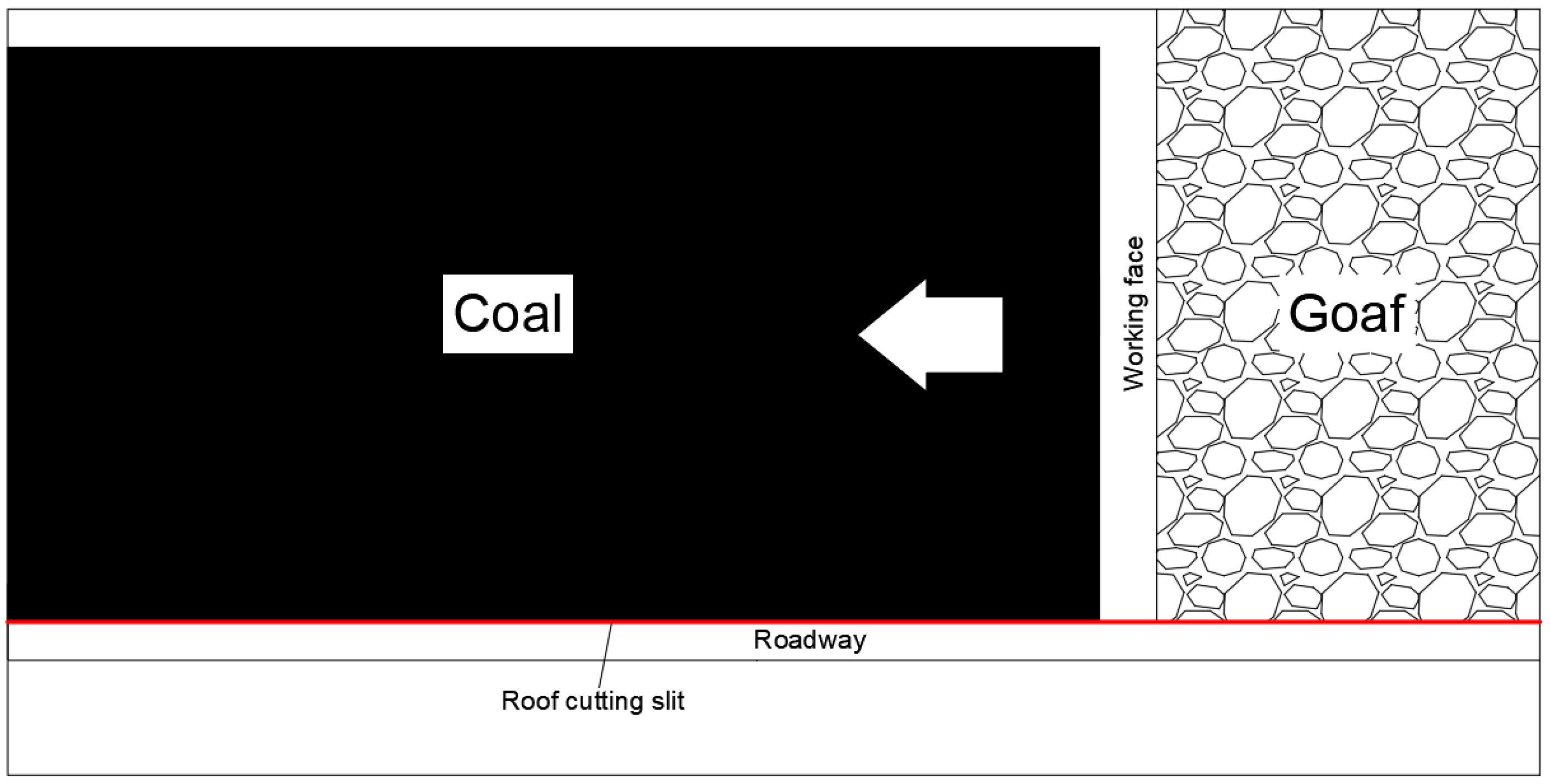
Figure 1. Diagram of the 1127 (1) working face of Guqiao Coal Mine.
Applsci 14 11779 g001
Figure 2. Comprehensive column of the rock strata in the 1127 (1) working face of Guqiao Coal Mine.
Applsci 14 11779 g002
Figure 3. Basic roof breaking structure and force analysis by roof cutting and pressure relief.
Applsci 14 11779 g003
Figure 4. Vertical stress distribution diagram of the roadway with different roof cutting angles: (a) uncut roof; (b) 10°; (c) 15°; (d) 20°.
Applsci 14 11779 g004aApplsci 14 11779 g004b
Figure 5. (a) Vertical stress curve of the roadway with different roof cutting angles; (b) vertical displacement curve of the roadway with different roof cutting angles.
Applsci 14 11779 g005
Figure 6. Vertical displacement distribution map of the roadway with different roof cutting angles: (a) uncut roof; (b) 10°; (c) 15°; (d) 20°.
Applsci 14 11779 g006
Figure 7. Vertical stress distribution diagram of the roadway with different roof cutting heights: (a) uncut roof; (b) 9 m; (c) 13.5 m; (d) 18 m.
Applsci 14 11779 g007
Figure 8. (a) Vertical stress curve of the roadway with different roof cutting heights; (b) vertical displacement curve of the roadway with different roof cutting heights.
Applsci 14 11779 g008
Figure 9. Vertical displacement distribution map of the roadway with different roof cutting heights: (a) uncut roof; (b) 9 m; (c) 13.5 m; (d) 18 m.
Applsci 14 11779 g009
Table 1. The parameters of the roof and floor of the coal seam.
Roof and Floor ParametersRock NameThickness/mRock Characteristics
Upper roofFine sandstone, sandy mudstone9.00White, thick layers, fine-grained structure, fracture development, siliceous and calcareous cementation, with horizontal and cross bedding; gray to grayish white, argillaceous cementation, contains plant fragments, dense
Immediate roofMudstone, carbonaceous mudstone,
11-3 coal
4.50Gray to dark gray, argillaceous cementation, brittle and fragile, sliding surface development, with a sense of sliding; top is 11-3 coal seam, black, powdery
Immediate bottomMudstone, 11-1 coal4.68Gray to dark gray, argillaceous cementation, brittle and easy to fall, sliding surface development, with a sense of sliding; bottom is 11-1 coal seam, black, powdered, small fragments
Old bottomSandy mudstone, siltstone5.15Gray to dark gray, argillaceous cementation, brittle and fragile;
gray-white, thick layer, silt structure, fracture development, siliceous and calcareous cementation, with horizontal and cross bedding
Table 2. Numerical simulation parameters of major coal and rock strata.
Rock NameVolumetric Weight d/(kg/m3)Bulk Modulus
K/GPa
Shear Modulus
G/GPa
Cohesion
/MPa
Angle of Internal Friction/°Compressive Strength
/MPa
Tensile Strength
/MPa
Fine sandstone28007.003.506.2031126.56.70
Sandy mudstone25105.704.302.903640.33.80
Mudstone22504.392.202.602838.63.20
Carbon mudstone23105.102.702.423334.72.90
11-2 coal14202.301.301.253012.52.30
Siltstone27006.504.006.003580.55.60
Disclaimer/Publisher’s Note: The statements, opinions and data contained in all publications are solely those of the individual author(s) and contributor(s) and not of MDPI and/or the editor(s). MDPI and/or the editor(s) disclaim responsibility for any injury to people or property resulting from any ideas, methods, instructions or products referred to in the content.