
An EV SRM Drive and Its Interconnected Operations Integrated into Grid, Microgrid, and Vehicle

Department of Electrical Engineering, National Tsing Hua University, Hsinchu 300035, Taiwan
*
Author to whom correspondence should be addressed.
Appl. Sci. 2024, 14(7), 3032; https://doi.org/10.3390/app14073032
Submission received: 21 February 2024
/
Revised: 28 March 2024
/
Accepted: 2 April 2024
/
Published: 4 April 2024
(This article belongs to the Special Issue Vehicle-to-Grid Systems: The Trends and Smart Grid Interaction Technologies)
Abstract
:This paper presents an electric vehicle (EV) switched reluctance motor (SRM) drive with incorporated operation capabilities integrated into the utility grid, the microgrid, and another EV. The motor drive DC-link voltage is established from the battery through an interleaved boost/buck converter with fault tolerance. The varied DC-link voltage can improve driving performance and reduce battery energy consumption over a wide speed range. Through a well-designed current control scheme, speed control scheme, and dynamic commutation tuning scheme, the established SRM drive possesses good performance in the motor driving mode. During deceleration, the regenerative braking energy can be effectively recovered to the battery. When the EV is in idle mode, the grid-to-vehicle (G2V) charging operation can be conducted through the bidirectional switch mode rectifier (SMR) and CLLC resonant converter. Satisfactory charging performance with good line drawn power quality and galvanic isolation is preserved. Conversely, the vehicle-to-grid (V2G) discharging operation can be performed. The EV can make movable energy storage device applications. Finally, the interconnected operations of the developed EV SRM drive to vehicle and microgrid are presented. Through vehicle-to-vehicle (V2V) operation, it can supply energy to the nearby EV when the battery is exhausted and needs roadside assistance. In addition, microgrid-to-vehicle (M2V) and vehicle-to-microgrid (V2M) operations can also be conductible. The EV battery can be charged from the microgrid. Conversely, it can also provide energy support to the microgrid.
1. Introduction
In recent years, the climate warming and energy crisis due to extra consumption of fossil fuels is becoming worse and has received much attention worldwide. The employment of EVs to replace the conventional internal combustion engine (ICE) vehicle can effectively reduce fossil energy consumption and carbon dioxide emissions, thus lessening the aforementioned problems. Similarly, the popularization of a microgrid using renewable sources also possesses these benefits. Moreover, the cooperated M2V/V2M operations can further boost these purposes. The development of EV SRM drives and performing M2V/V2M operations are presented in this paper.
Basically, EVs can be categorized into hybrid EV (HEV), plug-in HEV (PHEV), and battery EV (BEV). Until now, although various types of EVs have been extensively commercialized, there are still many technical aspects that need to be continuously improved and developed. The reviews for existing EV technologies can be referred to in [1,2,3], and the future development trends and challenges are explored in [2,3]. In the comparative environment aspects between ICE vehicles and EVs, much typical research has been made from the viewpoints of eco-driving effects [4], urban traffic energy chain and efficiency [5], well-to-wheel emission [6], and carbon footprint of city electric buses [7], etc.
Until now, the induction motor (IM) and the permanent magnet synchronous motor (PMSM) have been the mainstream motors for EVs due to their high power density, high efficiency, and mature technologies. However, the switched reluctance motor (SRM) still possesses potential for EV application [8,9,10] owing to its inherent merits. It is (i) suited for high speed driving with its simple and rigid structure; (ii) it has no magnet on its rotor, reducing the cost, and is cogging torque free; (iii) it has high generating torque and acceleration capability like a series DC motor. But, some key issues [11,12,13,14,15,16,17] should be properly treated to counteract its nonlinear torque generating characteristics and back electromotive force (EMF) effects. The current control should be the first concern [11,12,13,14]. The hysteresis current control and average PWM current control are typical methods for SRM. The hysteresis current control is robust and model-free. Regarding the average PWM current control, its control characteristics are highly affected by the design of the feedback controllers. It is suggested to apply the back-EMF feedforward control to compensate the influence of back-EMF [14]. When SRM is driven at high speed, the winding back-EMF will worsen the current response. To reduce the effects, it is necessary to adopt the commutation shifting approach to properly adjust the turn-on and turn-off angles of the phase current [14,15]. As generally recognized, SRM inherently possesses higher ripple torque, vibration, and acoustic noise owing to the doubly salient structure and concentrated armature windings. A typical example that studies the reduction of these defects can be found in [16,17].
In the propulsion system, there are two DC-link structures. One is the battery direct-powered DC-link. Without voltage boosting ability, the battery voltage level must be adequately set considering speed and load ranges. The other is the battery with followed interface converter. Adding a bidirectional DC/DC converter between the motor drive and the battery can make the motor drive DC-link voltage more stable and adjustable [18,19]. The battery voltage selection will be more flexible, and better driving performance over wide speed range can be achieved. In addition, the propulsion system with this structure makes the onboard battery more compatible with other hybrid energy storage sources. In [20], DC-link voltage and temperature variations are considered in the EV traction system design. And the voltage control approach for a Z-source inverter-fed PMSM drive is presented in [21]. Some DC/DC converters used for interface converters can be found in [18,22,23,24]. For an EV drive with regenerative braking capability, bidirectional converters [18] must be adopted. On the other hand, interleaved converters can be employed to have fault tolerance and lower current ripples [24]. In the developed EV SRM drive, the interleaved boost/buck converter is adopted as the battery followed interface converter.
For an EV, it is necessary to make the grid-to-vehicle (G2V) charging operation [25,26,27,28,29,30] through the onboard charger when the EV is in idle mode. The charger can be formed using integrated schematics [25,30], or can be added externally. Generally, battery charging can be classified between level 1 and level 3 [31,32,33]. The related standards can be found in [32,33]. Limited by size and weight, the EV onboard charger usually performs level 1 and level 2 charging levels. In order to conduct G2V operation, the EV charger usually includes an AC/DC switch mode rectifier (SMR) to possess the power factor correction (PFC) function, and a DC/DC converter is equipped to control the charging voltage and current. The survey for some existing SMRs is referred to in [34,35,36]. And some control researches for SMRs are presented in [37,38,39]. Furthermore, galvanic isolation is required for safety reasons. Despite a low frequency transformer for galvanic isolation being very simple to use, it is too bulky and heavy to equip on the vehicle. To solve this problem, one can employ the dual active bridge (DAB) converter using a high-frequency (HF) transformer [40,41]. Moreover, the CLLC resonant converters [42,43] can be applied to have higher efficiencies.
EVs can reduce carbon emissions in transportation. However, charging during peak hours will increase grid demand, which may produce additional carbon emissions in the electricity sector. Therefore, adopting EV grid-connected operations can reduce the carbon emissions of power generation. With bidirectional onboard chargers, EVs can conduct the vehicle-to-grid (V2G) operation [44,45,46]. When the grid demand is high, EVs can provide battery power to support the grid, which can utilize the energy effectively. However, the impacts on the grid must be considered [47,48,49]. With the equipped schematic for V2G, EV-to-home (V2H) [50] and EV-to-building (V2B) [51] can also be made. For the V2B operation, the energy management optimization controls considering uncertain PV energies can be found in [51].
There also exist some possible interconnected operations regarding EVs. Vehicle-to-vehicle (V2V) [52,53,54] is one example application. It may be applied in roadside assistance for EVs. In [55,56,57], the V2V operations using the onboard charger schematic and motor windings are presented. When an EV has exhausted its battery-stored energy, it can be charged from another EV. The other possible interconnection is EV to microgrid, performing microgrid-to-vehicle (M2V) and vehicle-to-microgrid (V2M) operations [58,59,60]. The EV battery can be charged from the microgrid. Effectively utilizing the renewable energies to charge the EV battery can reduce the charging power needed from the grid and consumed fossil energy [61,62,63]. Conversely, as the energy deficiency in the microgrid occurs, the EV battery can provide energy support to the microgrid. The interconnection between the microgrid and EVs can express their complementarities. Regarding the popularization of G2V charging and V2G discharging operations between EVs and the utility grid, many reliability, safety, functionality, interference, and harmonic impacts to the grid are explored in [64,65,66].
2. System Configuration of the Developed EV SRM Drive
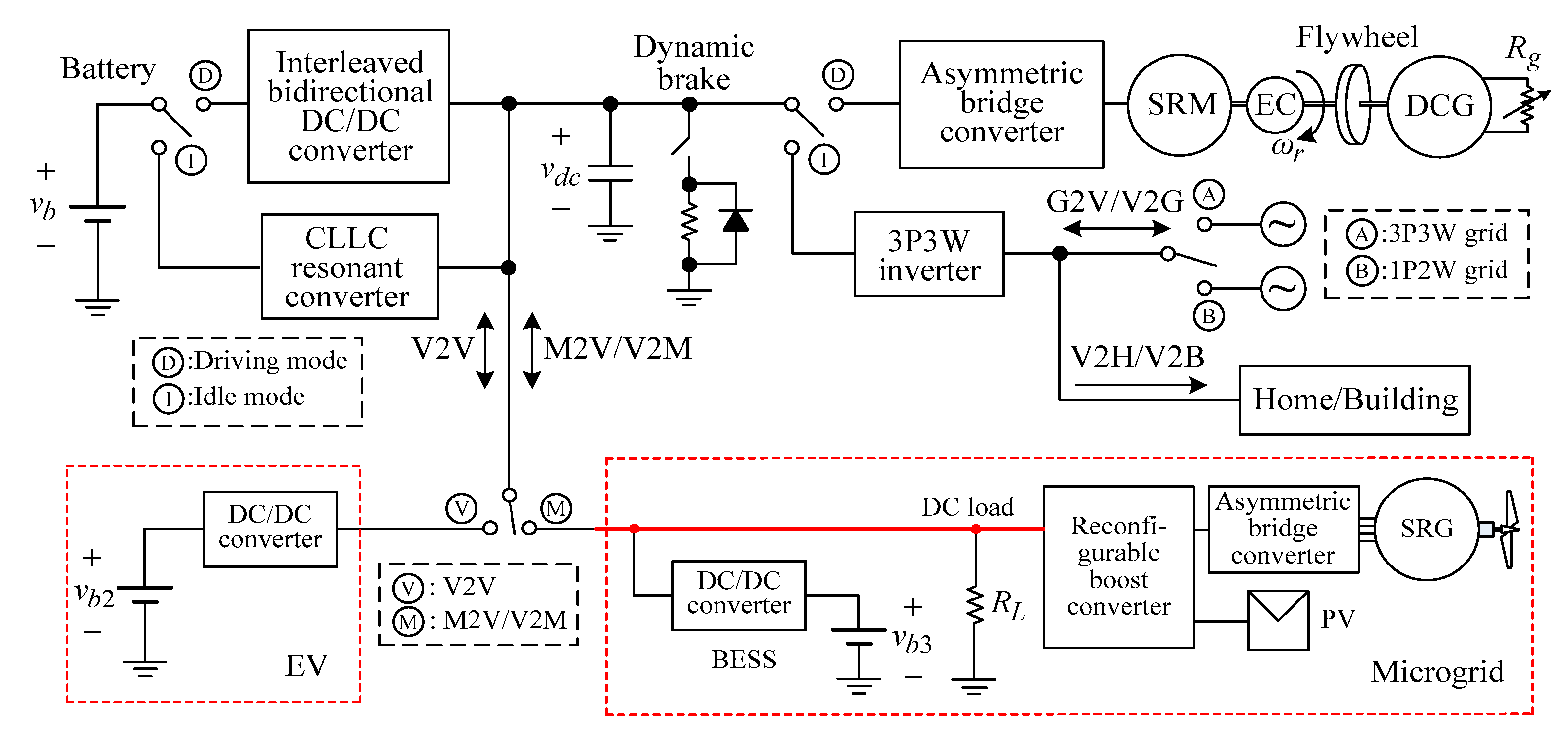
The developed EV SRM drive with G2V/V2G/V2V/M2V/V2M functions is depicted in Figure 1. The battery-powered EV drive consists of an interleaved bilateral battery interface converter, an asymmetric converter fed SRM, a mechanically coupled DC generator (DCG) with load resistor, a flywheel (FW) mounted on the motor shaft, and a dynamic brake leg. The DCG serves as the dynamic load for the studied SRM. The FW is added to increase the stored kinetic energy for facilitating the regenerative braking operation when the motor is decelerated. The incremental encoder (EC) with (A,B,Z) signals is used to detect the SRM rotor position. The resolution of the employed EC is (2500 pulse/rev).
In driving mode, the SRM drive varied DC-link voltage is established by the battery via an interleaved bidirectional boost/buck converter. The improved motor driving performance over a wide speed range with reduced battery energy consumption can be achieved. In idle mode, the grid-connected G2V/V2G operations are conducted through the bidirectional CLLC resonant converter and the bidirectional 3P3SW inverter. The bidirectional inverter is operated in inverter mode under V2G operation, and conversely as an SMR when conducting the G2V charging operation. With the same schematic, the vehicle-to-home and vehicle-to-building operations are directly applicable. The critical loads normally powered by the grid can be transferred to the EV, providing uninterruptible power as the grid power failure occurs. In addition, the V2V and/M2V/V2M operations can also be conductible. The functional blocks are shown in Figure 2a,b.
3. EV SRM Drive
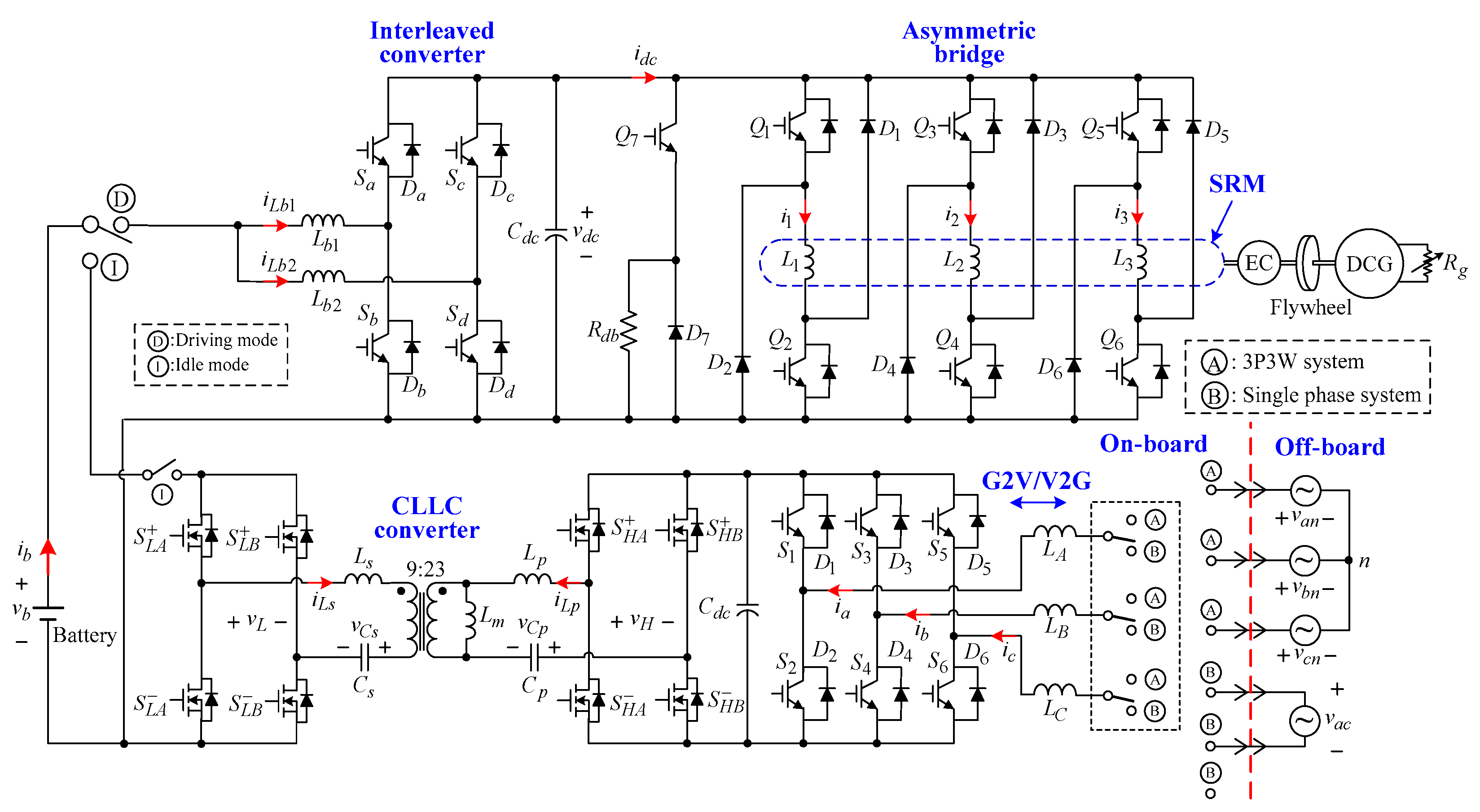
The detailed power circuit of the established EV SRM drive with isolated grid-connected function is shown in Figure 3. The motor drive DC-link voltage is established by the battery via an interleaved bidirectional interface DC/DC converter. To prevent the DC-link from overvoltage due to the failure of regenerative braking, a chopped dynamic braking leg is added across the DC-link. The basic SRM drive with fixed DC-link voltage is first established. Then, the EV SRM drive with varied DC-link voltage provided by the battery interface converter is developed.
3.1. DC Source-Powered Fixed DC-Link Voltage SRM Drive
3.1.1. Power Circuit
In the SRM drive shown in Figure 3, the DC-link is directly powered using a commercial DC power supply with fixed voltage. The constituted system components are summarized as follows:
- (a)
- SRM: three-phase, 12/8, 380 V, 2000 rpm, 2.2 kW.
- (b)
- Asymmetric bridge converter formed using six IGBT modules CM100DY-12H (Mitsubishi Company) (, continuous current , peak current ).
- (c)
- Dynamic brake constructed by an IGBT module CM100DY-12H and a braking resistor with
- (d)
- Dynamic load: FW and DCG are coupled to the SRM shaft to serve as its mechanical load. FW is added to increase the stored kinetic energy for the ease of performing regenerative braking.
3.1.2. Control Scheme
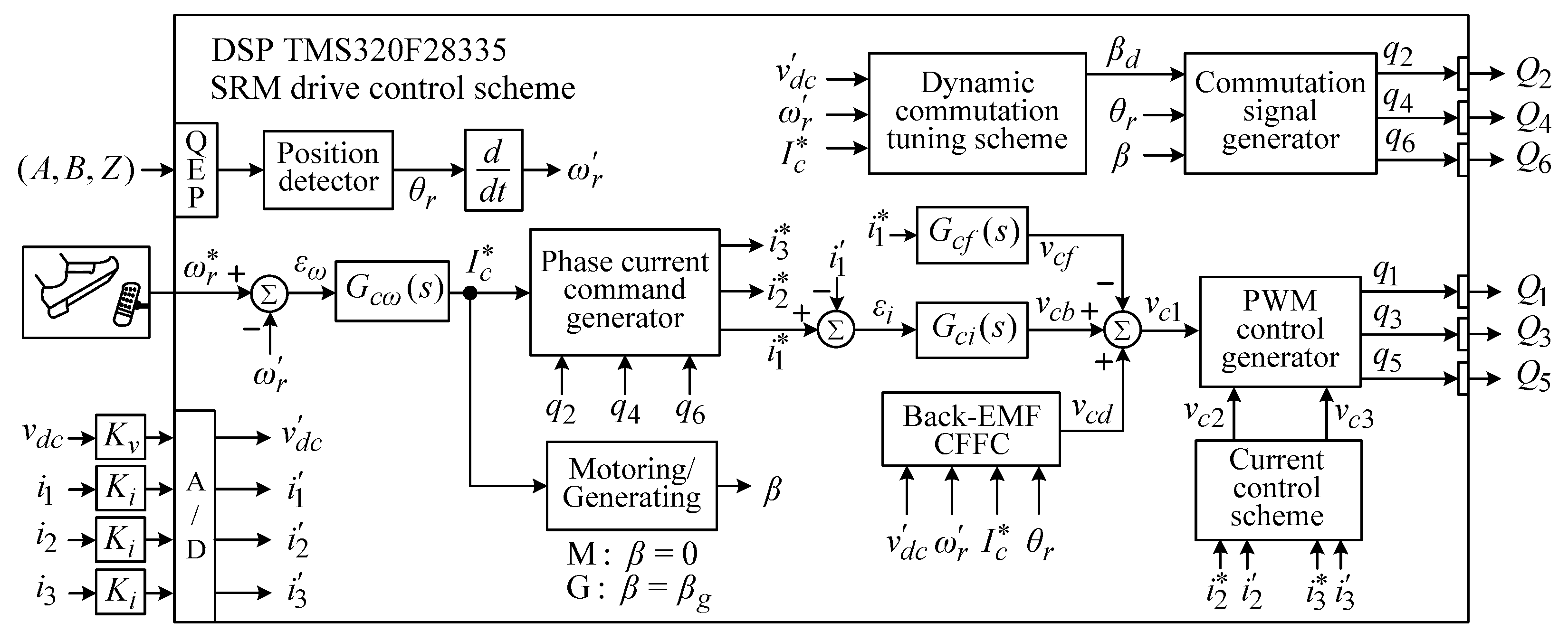
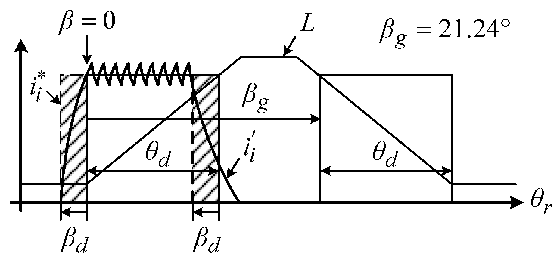
The proposed control scheme of the SRM drive is shown in Figure 4. It consists of an outer speed loop, inner current loop, commutation scheme, and PWM switching scheme. In driving mode, the dynamic commutation tuning (DCT) scheme generates the advanced shift angle to improve the current tracking response. The back-EMF current feedforward controller (CFFC) yields the control voltage according to the motor speed, observed inductance slope, rotor position, and current command to compensate the effects of back-EMF under high speed and heavier load. As the DC-link voltage exceeds the preset value (570V), the dynamic braking leg chopped operation will be activated. To let the EV SRM drive successfully perform regenerative braking in deceleration, when the current command becomes negative, the commutation angle will be shifted backward to let SRM operate as an SRG. The relationship between , , and dwell angle () is shown in Figure 5.
- (a)
- Dynamic commutation tuning scheme
As shown in Figure 5, the DCT scheme is proposed to shift the commutation angle forward automatically, which excites the stator winding at the small inductance slope region (). By neglecting the winding resistance and back-EMF, and assuming the constant winding inductance (), the advanced shifted time interval and angle can be estimated to let the winding current be raised to the command as follows:
- (b)
- Current control scheme
In the proposed current control scheme of each phase shown in Figure 4, the PWM control force is composed of the following: (i) the feedback control voltage by the current controller ; (ii) the back-EMF feedforward term ; and (iii) the current command feedforward term . The sensing factor for the winding current is , the DC-link voltage sensing factor is , and the motor speed sensing factor is .
- (1)
- Back-EMF current feedforward controller (CFFC)
Based on the estimated SRM inductance slope, the back-EMF feedforward control terms can be determined as:
where
- (2)
- Current feedback controller
The current controller is set to PI type as:
Due to the DCT scheme, it is assumed that the winding inductance is the smallest at the beginning of the commutation and there is no back-EMF effect. By setting winding resistance , and the desired closed- loop current tracking transfer function with bandwidth and damping ratio , parameters and can be derived as:
- (c)
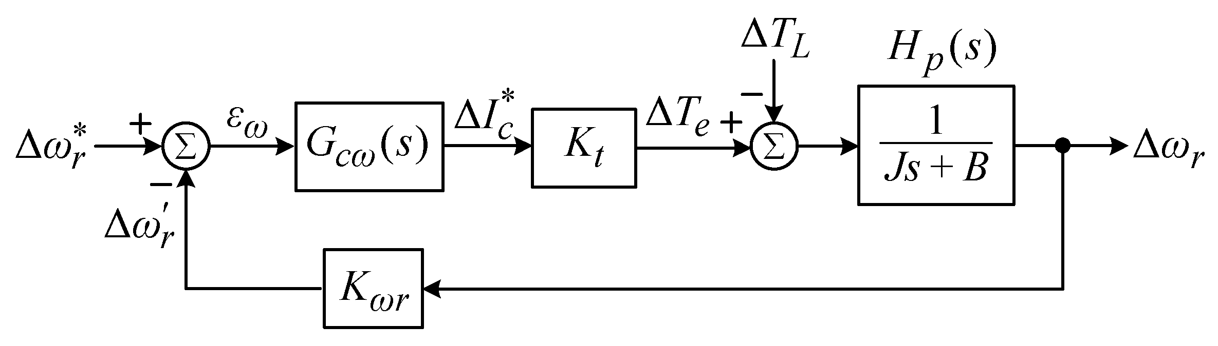
- Speed control scheme
After obtaining a well-tracking current through the proposed current control scheme and DCT scheme, SRM drive speed dynamic behavior can be represented by the control block shown in Figure 6, where is the speed controller, is the torque generating constant, and the dynamic model is:
The dynamic model parameters are estimated using a step response approach at under no load () to be:
The speed controller is set to PI type as:
The closed-loop transfer function can be derived from Figure 6 as:
The desired speed tracking response is defined by a first-order reference model:
By letting , one can derive to yield:
The desired is chosen. From (11), the designed speed controller parameters can be found to be:
The simulated speed tracking response by the designed PI controller due to the speed command change at is shown in Figure 7a. The result indicates that the response specified in (10) with is satisfied. Under the same condition, Figure 7b depicts the measured response, which is very close to the simulated one.
3.1.3. Measured Results
The developed EV SRM drive is powered by a commercialized power supply with . Some measured results are provided to verify the designed control schemes.
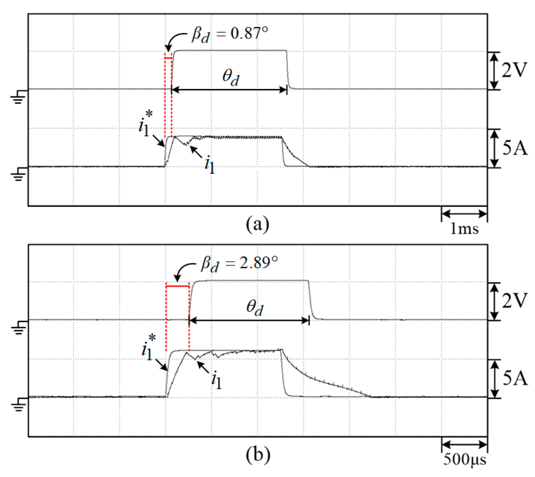
The measured and without the DCT scheme under at two speeds are shown in Figure 8. The results show that the winding current response becomes slower as the speed is increased, owing to the effects of back-EMF. The measured with the DCT scheme under at 1000 rpm and 2000 rpm are shown in Figure 9a,b, wherein the advanced shift angle and dwell angle are labeled. The convention of the defined and are shown in Figure 5. In Figure 8b and Figure 9b, one can find that the current response in high speed is improved by adopting the DCT scheme. Without applying the advanced shift, the winding current becomes single-pulse mode without PWM switching. After applying the proposed DCT approach, the PWM switched winding current with smaller magnitude is yielded.
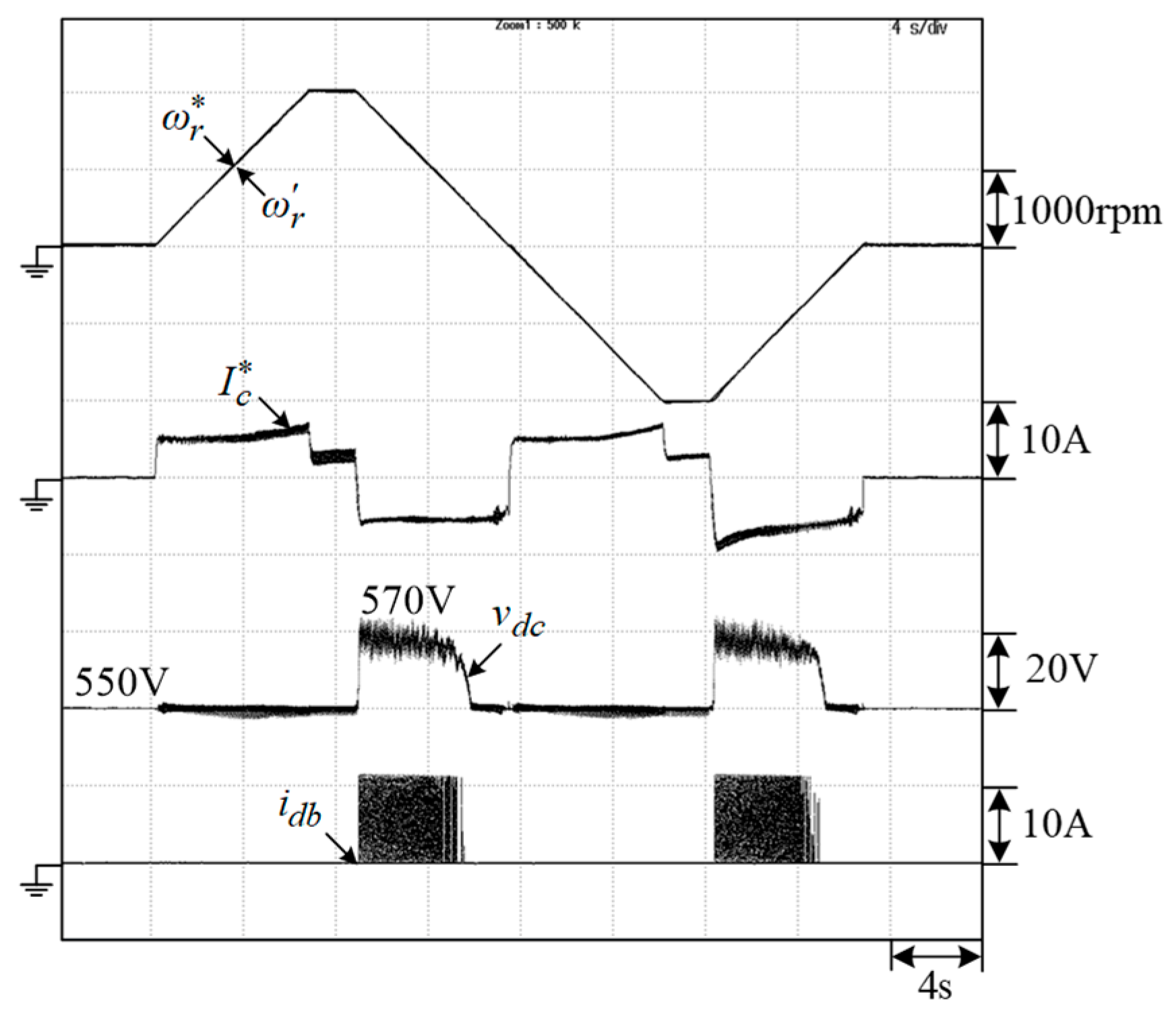
A dynamic braking leg is connected across the DC-link to limit the DC-link voltage at during deceleration. The measured developed SRM drive due to the reversible speed command at with acceleration and deceleration rates of 300rpm/s is shown in Figure 10. The satisfactory control performances, including reversible running, generator operation of SRM, and dynamic braking voltage limitation caused by the recovered stored kinetic energy, are seen in the results.
3.2. Battery-Powered Varied DC-link Voltage SRM Drive
3.2.1. Battery Interface DC/DC Converter
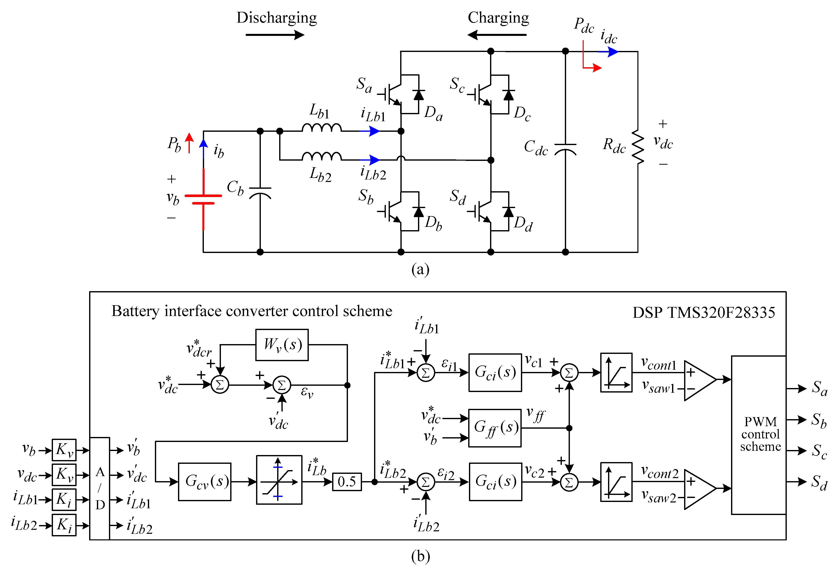
Figure 11a,b show the schematic and control scheme of the established interleaved boost/buck converter with two cells. The switching signals between the two cells are phase-shifted by . The interface DC/DC converter can be operated in the following modes:
- (a)
- Discharging mode. In the motor driving operation, the DC-link voltage is established from the battery voltage in boost mode.
- (b)
- Charging mode. In the battery charging mode or regenerative braking mode, the power flow is from to . The bidirectional boost/buck converter is operated as a buck DC/DC converter.
The power circuit and control scheme of the interface converter are specifically designed in boost mode. The designed components are also employed under buck mode, with the adequacy being verified.
- (a)
- Power circuit
The ratings and the designed system parameters are as follows:
- (1)
- Ratings: , .
- (2)
- Battery bank: nominal voltage .
- (3)
- PWM switching frequency: .
- (4)
- DC-link capacitor: .
- (5)
- Battery side capacitor: .
- (6)
- Energy storage inductors: and at 20 kHz.
- (b)
- Control scheme.
The control scheme shown in Figure 11b consists of an outer voltage loop and an inner current loop. The current command of each cell ( and ) is generated by the voltage controller . And the PWM control signal of the two cells ( and ) is yielded by the current controller . The two PWM control signals are compared with two sawtooth waves ( and ) phase-shifted by to generate the switching signals.
- (1)
- Current controller
- (i)
- Feedback controller
The compensated control characteristics of the current closed-loop gain are defined as having the crossover frequency at 1 kHz with a phase margin of . The designed controller is:
- (ii)
- Feedforward controller
The feedforward controller added to yield-improved current tracking response is set as:
Through the feedforward controller, the duty ratio can be directly set to yield the desired from the sensed .
- (2)
- Voltage controller
The compensated control characteristics of the voltage closed-loop gain are defined as having the crossover frequency at 20 Hz with the phase margin . The designed voltage feedback controller is:
Moreover, a robust controller with the weighting function is added. To enhance the dynamic response, the weighting function is set as:
3.2.2. Battery-Powered EV SRM Drive
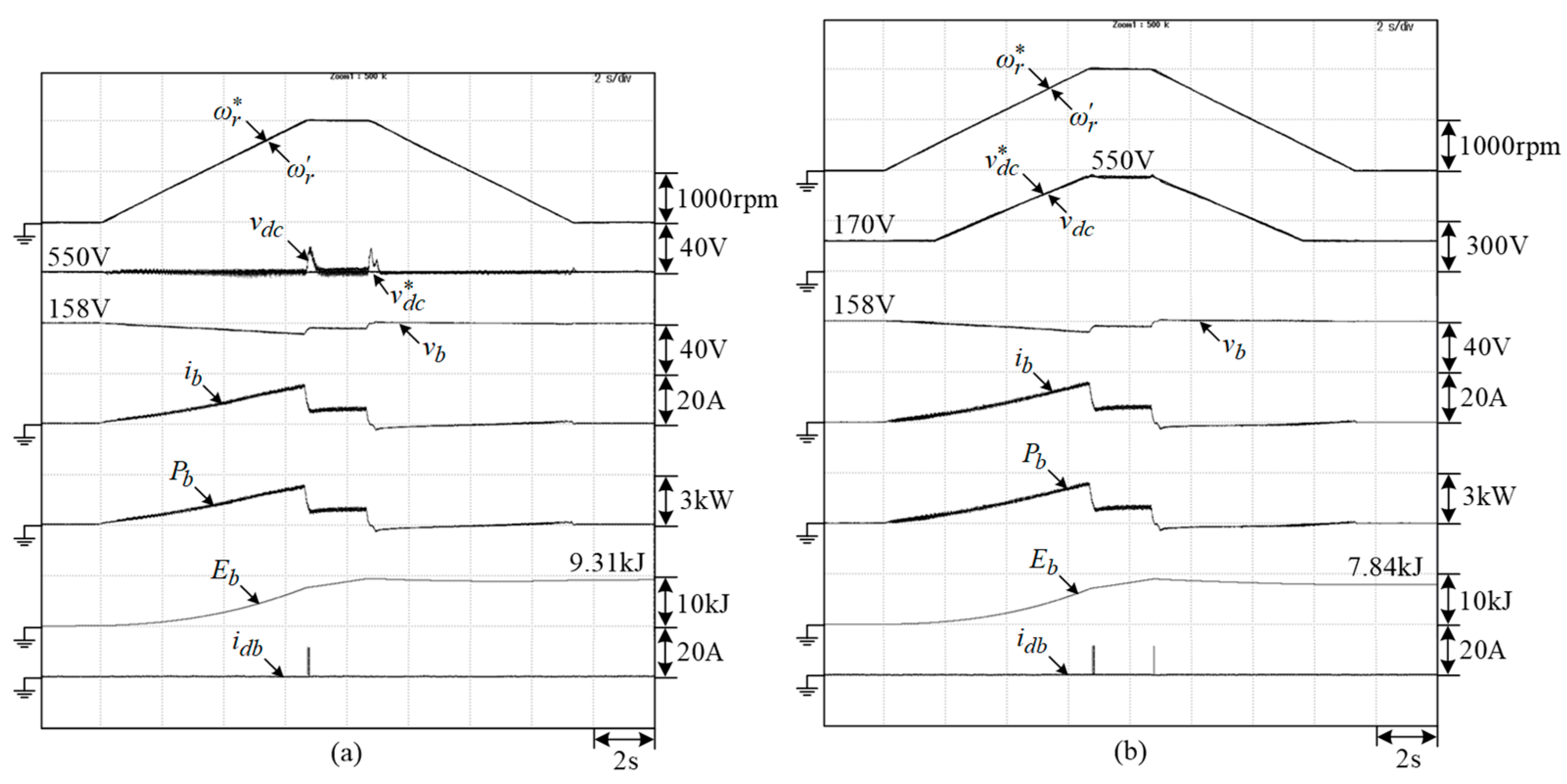
In the developed EV drive, the DC-link voltage command is set depending on the motor speed. The DC-link voltages set for comparison are listed below:
- ➢
- Fixed DC-link voltage: , .
- ➢
- Varied DC-link voltage: , .
, .
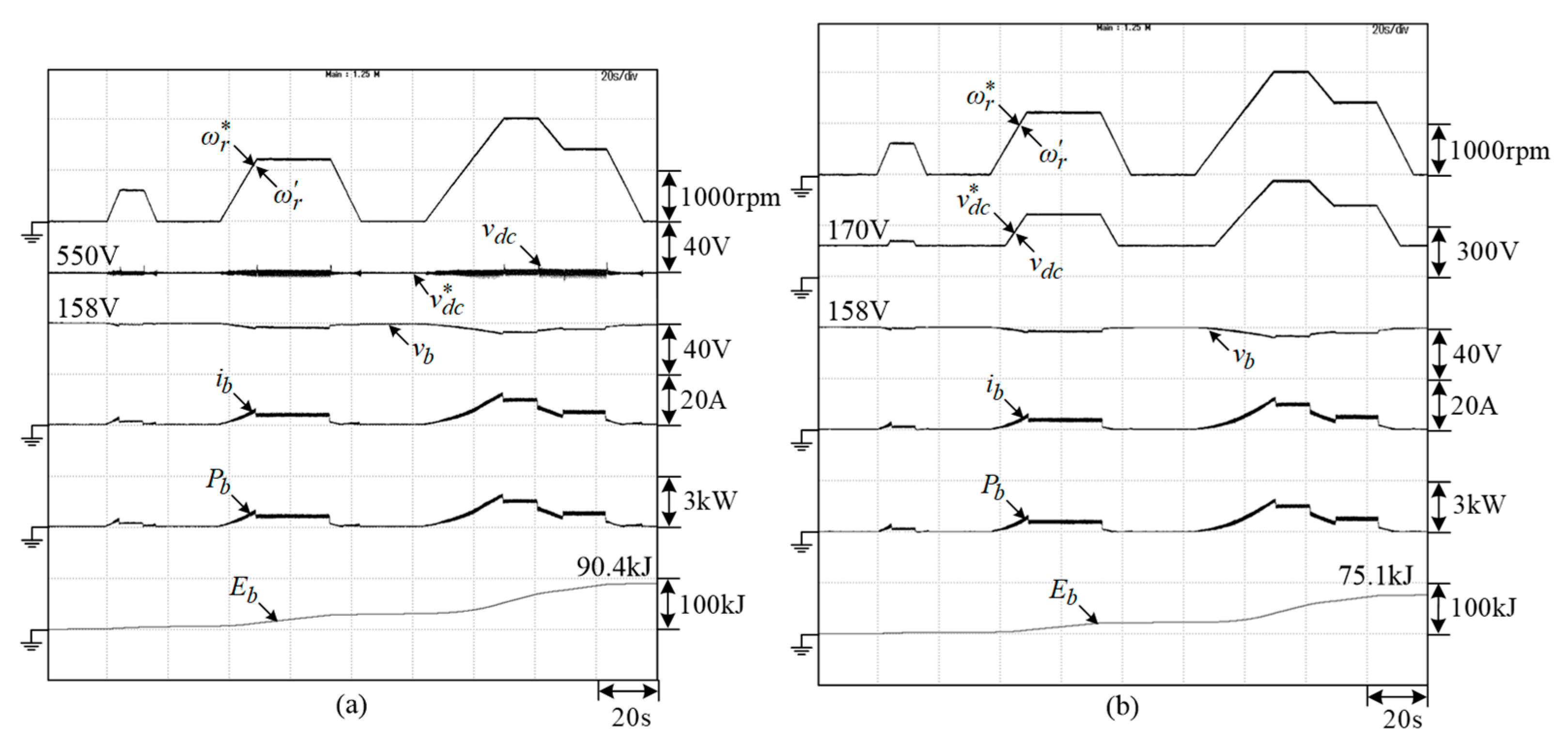
The measured results of the EV SRM drive under fixed and varied DC-link voltages with trapezoidal speed command at are shown in Figure 12. Note that represents the battery output power, and represents the battery consumed energy. The battery energy is under varied voltage compared with under fixed voltage. Figure 13 shows the measured results of the SRM drive under the speed pattern defined by ECE15 at with fixed and varied DC-link voltages. The reduction of battery energy from to can also be observed.
4. G2V/V2G Operations
By setting the mode switch in Figure 3 at position “I”, the isolated grid-connected G2V/V2G operations can be conducted. The schematic consists of a CLLC resonant converter and a bidirectional PWM inverter.
4.1. Bidirectional CLLC Resonant Converter
4.1.1. Power Circuit
The power circuit of the established CLLC resonant is shown in Figure 14. The ratings and system parameters are given as follows:
- Primary side voltage: ; secondary side voltage: .
- Rated power: . The maximum charging voltage is set to 158 V and the maximum charging current is 10 A in charging mode.
- Nominal switching frequency: .
- Duty ratio: fixed in .
- Transformer turn ratio: .
- Employed ferrite core EE5525 is manufactured by A&T MAGNETICS Co., Ltd. (New Taipei City, Taiwan).
- Measured magnetizing inductance and other resonant circuit parameters: , , , , .
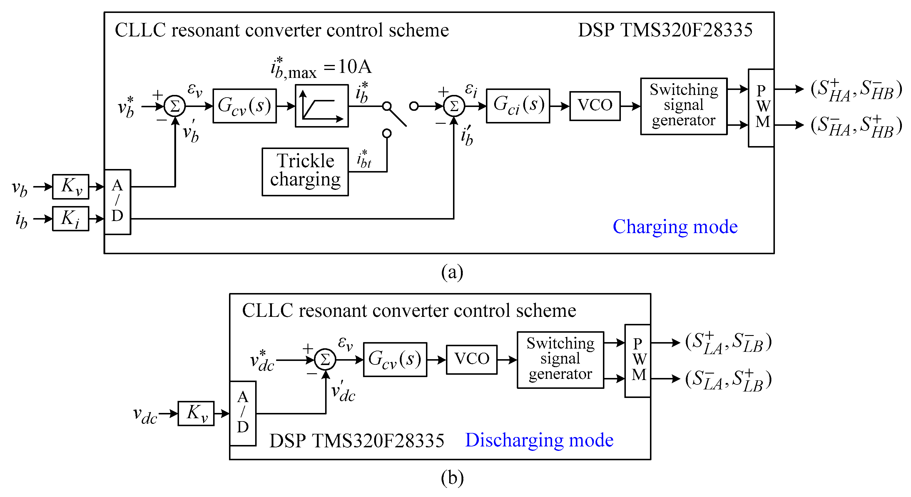
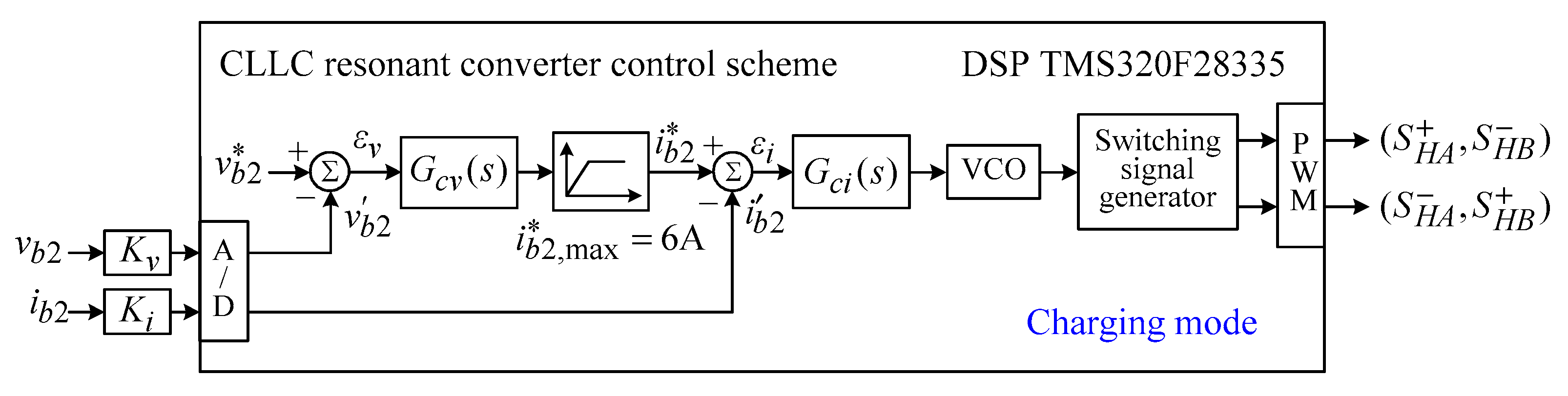
4.1.2. Control Scheme
The control schemes of the CLLC resonant converter in two operation modes are shown in Figure 15a,b.
- (a)
- Charging mode
- (1)
- Normal G2V charging
In the control system shown in Figure 15a, the battery voltage command is set at 158 V. And the current command is yielded by the outer voltage loop and is limited at 10 A. Hence, before the battery voltage reaches 158 V, the battery charges in a constant current mode at 10 A. Then, the constant voltage mode is applied after the voltage reaches 158 V.
Through trial-and-error, the voltage feedback controller and current feedback controller are set to PI type as:
- (2)
- Trickle charging
The self-discharging phenomenon will reduce the battery store energy and the driving endurance range. To compensate this loss, the current command in Figure 15a is set as with a suitably low value for making the trickle charge [67,68].
- (b)
- Discharging mode
In the discharging mode, only the voltage loop is arranged. The DC-link voltage is well-regulated at via modulated switching frequency. Through trial-and-error, the voltage feedback controller is set to PI type as follows:
4.2. Grid-Connected Three-Phase SMR/Inverter
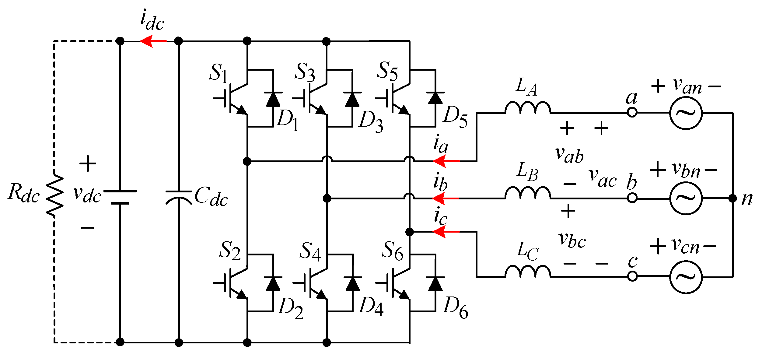
4.2.1. Power Circuit
The schematic of the established grid-connected SMR/inverter is shown in Figure 16, with the following specifications and system components:
- Three-phase AC line voltage: .
- DC-link voltage:
- PWM switching frequency: .
- DC-link capacitor: .
- Energy storage inductors: the three inductors are .
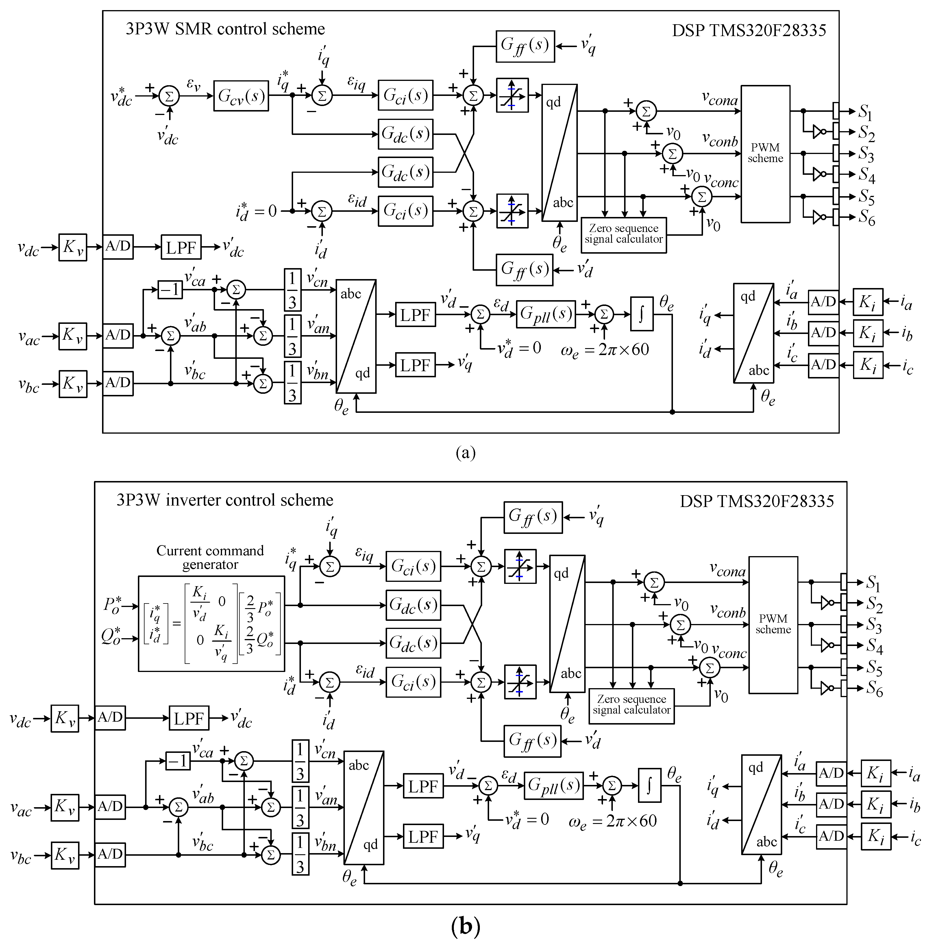
4.2.2. Control Scheme
Figure 17 shows the control scheme of the 3P3W SMR/inverter in G2V charging and V2G discharging operations. The detailed controller parameters are introduced as follows.
- (a)
- G2V operation
- (1)
- Phase-locked loop controller
The PLL controller is chosen to be PI type via trail-and-error as:
- (2)
- Current controller
The decoupling controller and feedforward controller are set as follows:
where and are current and voltage sensing factors, respectively. is the PWM transfer ratio, where is the amplitude of triangle carrier and is the inductance of energy storage inductors.
By assuming the ideal feedforward and decoupling controls, the current closed-loop transfer function between and can be specified by a first-order transfer function with time constant . Giving and using the known data, , , , and , one can find the current controller:
- (3)
- Voltage feedback controller
At the given operation point , the voltage regulation control specifications are defined as and . Due to the step power change, . Through careful derivation, one can find that:
- (b)
- V2G operation
Figure 17b shows the control scheme of the 3P3W inverter in V2G operation. The PLL controller and current controller parameters are set the same as those in G2V mode. The q-axis current command and d-axis current command can be obtained through the current command generator depending on the real power command and reactive power command . Generally, is set to reach a unity power factor.
4.3. Experimental Evaluation
The power circuit of the developed EV SRM drive in conducting the grid-connected G2V/V2G operations is shown in Figure 18, which consists of a CLLC resonant DC/DC converter and a six-switch inverter. In a G2V charging operation, the three-phase inverter acts as a PFC front-end SMR and charges the battery through the CLLC resonant converter. Regarding the V2G operation, the battery discharges power to the utility grid through the same power circuits. Reactive and harmonic power compensations can also be achievable.
4.3.1. G2V Operation
The battery charging voltage is set at , and the maximum charging current is set at . The charging process can be divided into a constant current mode and a constant voltage mode. In the constant current charging mode, the battery is charged with 10 A. The measured phase voltage and three line currents of the three-phase SMR are shown in Figure 19a, the of the CLLC resonant converter are shown in Figure 19b, and the voltage and current of battery and DC-link are shown in Figure 19c. Furthermore, the measured results in constant voltage charging mode are shown in Figure 20. The results of the two power stages indicate that (i) synchronized with , three-phase balanced, and lowly-distorted line currents verify the satisfactory performance of the SMR; (ii) normal operation of the CLLC converter can be observed from the waveforms of Figure 19b. The zero-voltage switching (ZVS) behavior is assured by the relationship between and ; and (iii) the constant current charging with () is achieved. As reaches 158 V, the constant voltage charging is applied automatically, with the results depicted in Figure 20a–c. The above similar comments can also be made for the measured results.
4.3.2. V2G Operation
The output real power of the developed inverter under V2G mode is set at 1 kW. The measured of the CLLC resonant converter are shown in Figure 21a, the voltage and current of battery and DC-link are shown in Figure 21b, and the phase voltage and three line currents are shown in Figure 21c. Furthermore, the measured results with and are shown in Figure 22, and the results with and are shown in Figure 23. The normal operations and good performances of the CLLC resonant converter and the 3P3W inverter under various scenarios are seen in the results. The preset real and reactive powers are successfully sent back to the utility grid.
5. V2V/V2M/M2V Operations
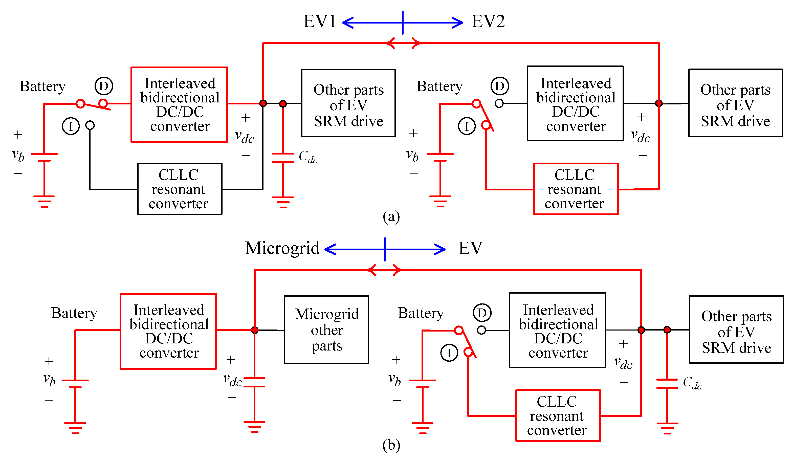
5.1. V2V Operation
5.1.1. System Configuration
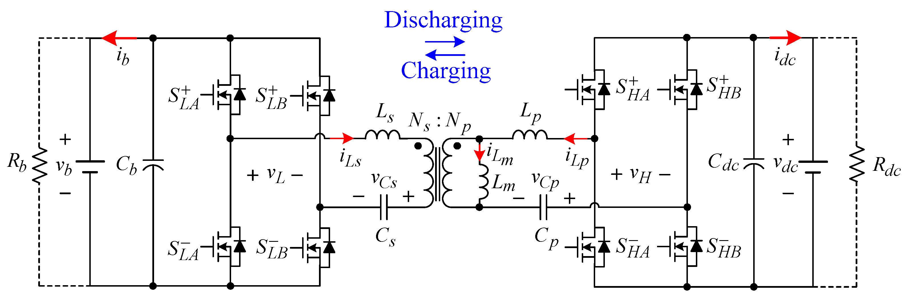
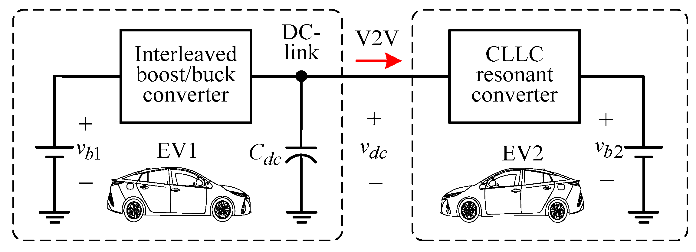
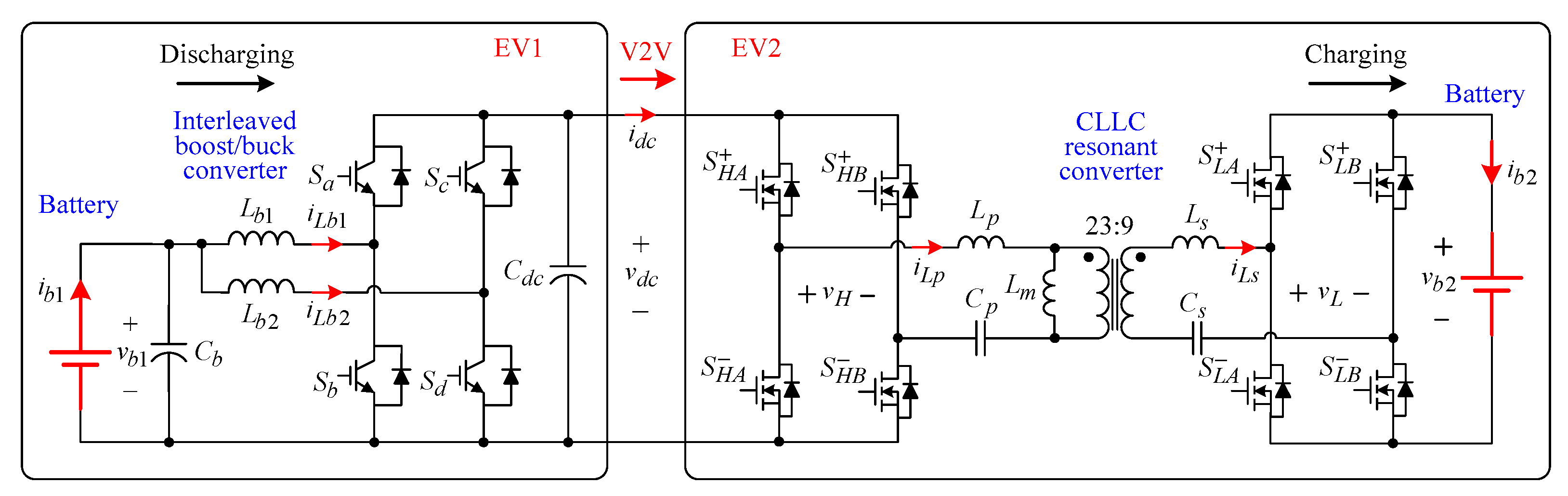
The system configuration of the developed V2V scheme is shown in Figure 24. EV1 is the vehicle providing energy, and EV2 is the other vehicle receiving energy for battery charging. The DC/DC converter in EV1 adopts the interleaved boost/buck converter. And the CLLC converter is used in EV2.
The detailed power circuit of the developed V2V scheme is shown in Figure 25. The specifications and system components are listed below:
- Nominal battery voltages: .
- DC-link voltage: .
- DC-link capacitor: .
- Energy storage inductors: .
- Switching frequency of interleaved boost/buck converter: .
- Nominal switching frequency of CLLC resonant converter: .
5.1.2. Measured Results
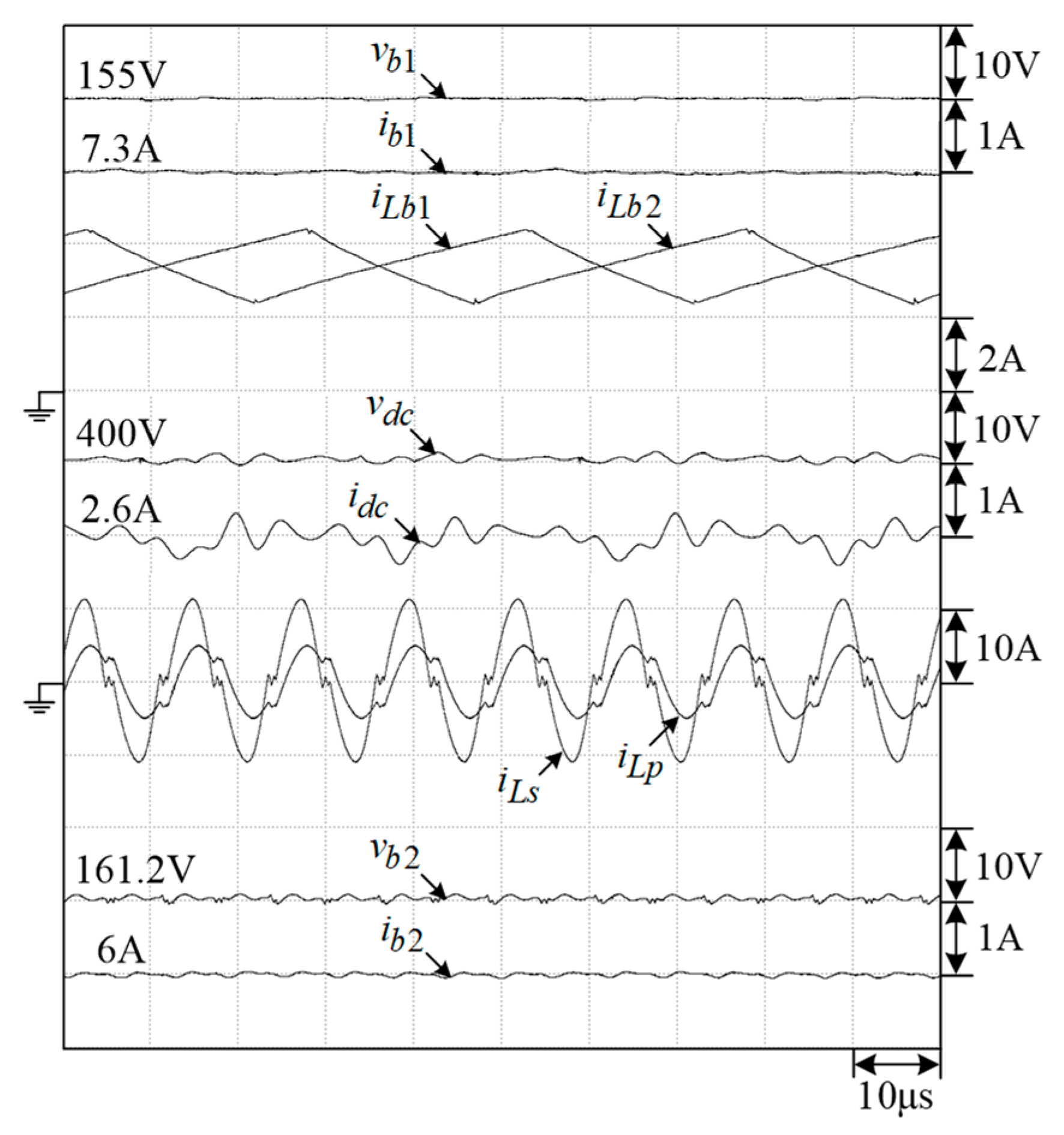
The measured results of the developed V2V scheme under charging current are shown in Figure 27. Good control performance can be observed. Figure 28 shows the measured results under charging current command change . Satisfactory dynamic responses can also be observed from the results. Figure 29 shows the measured results under the preset charging current command pattern , where and are the battery-consumed energy of EV1 and the received energy of EV2 calculated as:
5.2. M2V/V2M Operations
5.2.1. System Configuration
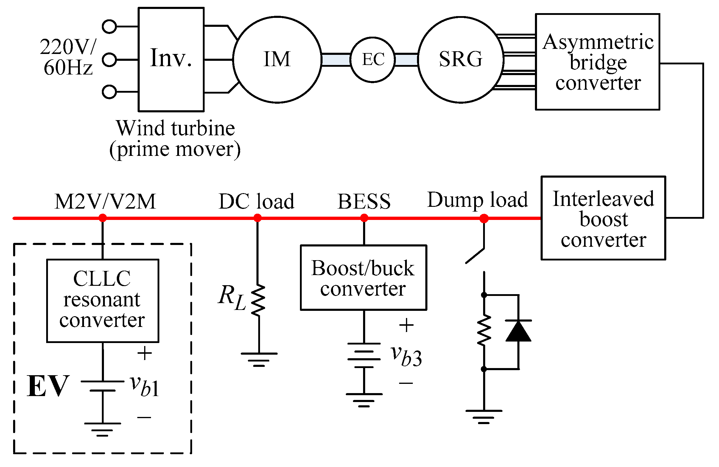
The bidirectional M2V/V2M operations can be performed by connecting the DC-link of the EV to the DC microgrid. Under the EV idle mode, the DC microgrid can charge the EV onboard battery in the M2V operation, while the battery can support the microgrid in the V2M operation. An available wind SRG/PV-based DC microgrid [67] is employed here for studying. The PV source is neglected for simplicity. Figure 30 shows the system configuration of the interconnected operation of the EV and the DC microgrid, and Figure 31 shows the detailed power circuit of the whole system. The asymmetrical bridge converter is applied to the SRG for the best control flexibility. Through the interleaved boost converter, the SRG output voltage is boosted to 400 V. The DC microgrid system consists of a dump load to prevent overvoltage, a battery energy storage system, and a DC load. The SRG control scheme and the DC microgrid system can be referred to in [69]. Some key parameters and system components of the wind SRG-based DC microgrid are listed below:
- SRG (4-phase 8/6): rated speed , rated power , rated voltage .
- Power switches: IGBT modules CM100DY-12H.
- DC-link voltage: .
- BESS: nominal voltage , capacity .
5.2.2. Measured Results
- (a)
- M2V operation
In the M2V operation, the microgrid DC-link voltage is established by the SRG and interleaved boost converter. The measured results of the M2V operation under battery charging power are shown in Figure 32. A successful charging operation can be seen in the results.
- (b)
- V2M operation
In the V2M operation, through the CLLC resonant converter on the EV, the onboard battery voltage is boosted to establish the microgrid common DC bus voltage. Then, it can supply the DC load in the microgrid and charge the battery in the BESS system. The measured results of the V2M operation under DC load power and battery charging power are shown in Figure 33. A successful discharging operation can be observed from the results.
- Summary: After establishing that the developed EV SRM drive has various interconnect functions, the operating characteristics of all modes are verified by a lot of measured results, which are briefly summarized as follows:
- (1)
- The battery directly powered basic EV SRM drive with is first verified, including speed dynamic response with defined specifications, the effect of DCT in enhancing the winding current response, the acceleration/deceleration, the reversible running, and the regenerative/dynamic braking operations.
- (2)
- The EV SRM drive is powered by battery via interleaved bidirectional interface converter. The fixed and varied DC-link voltages boosted from battery are used to power the motor drive, and their comparative performance is evaluated. The loss-consumed battery energies under the programed speed patterns yielded by various DC-link voltage approach are demonstrated, as shown in Figure 12 and Figure 13.
- (3)
- The G2V/V2G operations of the developed EV SRM drive are achieved by a CLLC resonant converter and a bilateral 3P3W inverter. The normal operations and satisfactory performance under G2V mode can be seen in Figure 19 and Figure 20. Regarding the V2G operation, the results presented in Figure 21, Figure 22 and Figure 23 demonstrate that the preset real and reactive powers are successfully sent back to the utility grid.
- (4)
6. Conclusions
This paper presents an EV SRM drive and its G2V/V2G/V2V/M2V/V2M operations. For the established SRM drive, the commutation shifting scheme, current, and speed control schemes are all properly designed to yield good dynamic and steady-state driving performance, including reversible and regenerative braking operations. Moreover, thanks to the varied-voltage DC-link arrangement, improved performance over a wide speed range and reduced battery consumed energy are achieved.
In idle mode, the isolated grid-connected G2V/V2G operations are successfully conducted based on the battery, CLLC resonant converter, and SMR/inverter. In G2V charging mode, the inverter is operated as a three-phase or single-phase SMR to charge the battery from the utility grid, with good PFC characteristics. Reversely, V2G operation can be performed for sending the real and reactive powers to the grid. Good performances have been verified from the measured results.
In V2V operation, thanks to the equipped EV power control units and proper power conditioning control arrangement, the EV with exhausted battery energy can be charged by the other EV providing auxiliary roadside assistance. Successful operation has been experimentally demonstrated. Moreover, the M2V/V2M operations of the developed EV SRM drive have also been experimentally demonstrated.
Author Contributions
Formal analysis, W.-K.G.; Writing—original draft, W.-K.G.; Writing—review & editing, C.-W.Y.; Supervision, C.-W.Y. and C.-M.L.; Project administration, C.-M.L. All authors have read and agreed to the published version of the manuscript.
Funding
This research received no external funding.
Institutional Review Board Statement
Not applicable.
Informed Consent Statement
Not applicable.
Data Availability Statement
The original contributions presented in the study are included in the article, further inquiries can be directed to the corresponding author.
Conflicts of Interest
The authors declare no conflict of interest.
References
- Silvas, E.; Hofman, T.; Murgovski, N.; Etman, L.F.P.; Steinbuch, M. Review of optimization strategies for system-level design in hybrid electric vehicles. IEEE Trans. Veh. Technol. 2017, 66, 57–70. [Google Scholar] [CrossRef]
- Husain, I.; Ozpineci, B.; Islam, M.S.; Gurpinar, E.; Su, G.J.; Yu, W.; Chowdhury, S.; Xue, L.; Rahman, D.; Sahu, R. Electric drive technology trends, challenges, and opportunities for future electric vehicles. Proc. IEEE Proc. 2021, 109, 1039–1059. [Google Scholar] [CrossRef]
- Ehsani, M.; Singh, K.V.; Bansal, H.O.; Mehrjardi, R.T. State of the art and trends in electric and hybrid electric vehicles. Proc. IEEE Proc. 2021, 109, 967–984. [Google Scholar] [CrossRef]
- Kato, H.; Ando, R.; Kondo, Y.; Suzuki, T.; Matsuhashi, K.; Kobayashi, S. Comparative measurements of the eco-driving effect between electric and internal combustion engine vehicles. In Proceedings of the 2013 World Electric Vehicle Symposium and Exhibition (EVS27), Barcelona, Spain, 17–20 November 2013; pp. 1–5. [Google Scholar]
- Righolt, H.C.; Rieck, F.G. Energy chain and efficiency in urban traffic for ICE and EV. In Proceedings of the 2013 World Electric Vehicle Symposium and Exhibition (EVS27), Barcelona, Spain, 17–20 November 2013; pp. 1–7. [Google Scholar]
- Athanasopoulou, L.; Bikas, H.; Stavropoulos, P. Comparative well-to-wheel emissions assessment of internal combustion engine and battery electric vehicles. Proc. Procedia CIRP 2018, 78, 25–30. [Google Scholar] [CrossRef]
- Lie, K.W.; Synnevåg, T.A.; Lamb, J.J.; Lien, K.M. The carbon footprint of electrified city buses: A case study in Trondheim, Norway. Energies 2021, 14, 770. [Google Scholar] [CrossRef]
- Rahman, K.M.; Fahimi, B.; Suresh, G.; Rajarathnam, A.V.; Ehsani, M. Advantages of switched reluctance motor applications to EV and HEV: Design and control issues. IEEE Trans. Ind. Appl. 2000, 36, 111–121. [Google Scholar] [CrossRef]
- Chiba, A.; Takano, Y.; Takeno, M.; Imakawa, T.; Hoshi, N.; Takemoto, M.; Ogasawara, S. Torque density and efficiency improvements of a switched reluctance motor without rare-earth material for hybrid vehicles. IEEE Trans. Ind. Appl. 2011, 47, 1240–1246. [Google Scholar] [CrossRef]
- Bilgin, B.; Howey, B.; Callegaro, A.D.; Liang, J.; Kordic, M.; Taylor, J.; Emadi, A. Making the case for switched reluctance motors for propulsion applications. IEEE Trans. Veh. Technol. 2020, 69, 7172–7186. [Google Scholar] [CrossRef]
- Kioskeridis, I.; Mademlis, C. A unified approach for four-quadrant optimal controlled switched reluctance machine drives with smooth transition between control operations. IEEE Trans. Power Electron. 2009, 24, 301–306. [Google Scholar] [CrossRef]
- Sikder, C.; Husain, I.; Sozer, Y. Switched reluctance generator control for optimal power generation with current regulation. IEEE Trans. Ind. Appl. 2014, 50, 307–316. [Google Scholar] [CrossRef]
- Peng, F.; Ye, J.; Emadi, A. A digital PWM current controller for switched reluctance motor drives. IEEE Trans. Power Electron. 2016, 31, 7087–7098. [Google Scholar]
- Huang, H.N.; Hu, K.W.; Wu, Y.W.; Jong, T.L.; Liaw, C.M. A current control scheme with back EMF cancellation and tracking error adapted commutation shift for switched-reluctance motor drive. IEEE Trans. Ind. Electron. 2016, 63, 7381–7392. [Google Scholar] [CrossRef]
- Mademlis, C.; Kioskeridis, I. Performance optimization in switched reluctance motor drives with online commutation angle control. IEEE Trans. Energy Convers. 2003, 18, 448–457. [Google Scholar] [CrossRef]
- Fang, G.; Scalcon, F.P.; Xiao, D.; Vieira, R.P.; Gründling, H.A.; Emadi, A. Advanced control of switched reluctance motors (SRMs): A review on current regulation, torque control and vibration suppression. IEEE Open J. Ind. Electron. Soc. 2021, 2, 280–301. [Google Scholar] [CrossRef]
- Sahu, A.K.; Emadi, A.; Bilgin, B. Noise and vibration in switched reluctance motors: A review on structural materials, vibration dampers, acoustic impedance, and noise masking methods. IEEE Access 2023, 11, 27702–27718. [Google Scholar] [CrossRef]
- Schoenen, T.; Kunter, M.S.; Hennen, M.D.; De Doncker, R.W. Advantages of a variable DC-link voltage by using a DC-DC converter in hybrid-electric vehicles. In Proceedings of the 2010 IEEE Vehicle Power and Propulsion Conference (VPPC 2010), Lille, France, 1–3 September 2010; pp. 1–5. [Google Scholar]
- Badawy, M.O.; Husain, T.; Sozer, Y.; De Abreu-Garcia, J.A. Integrated control of an IPM motor drive and a novel hybrid energy storage system for electric vehicles. IEEE Trans. Ind. Appl. 2017, 53, 5810–5819. [Google Scholar] [CrossRef]
- Zhao, N.; Schofield, N.; Yang, R.; Gu, R. Investigation of DC-link voltage and temperature variations on EV traction system design. IEEE Trans. Ind. Appl. 2017, 53, 3707–3718. [Google Scholar] [CrossRef]
- Xiao, S.; Gu, X.; Wang, Z.; Shi, T.; Xia, C. A novel variable DC-link voltage control method for PMSM driven by a quasi-Z-source inverter. IEEE Trans. Power Electron. 2020, 35, 3878–3890. [Google Scholar] [CrossRef]
- Bhaskar, M.S.; Ramachandaramurthy, V.K.; Padmanaban, S.; Blaabjerg, F.; Ionel, D.M.; Mitolo, M.; Almakhles, D. Survey of DC-DC non-isolated topologies for unidirectional power flow in fuel cell vehicles. IEEE Access 2020, 8, 178130–178166. [Google Scholar] [CrossRef]
- Alhurayyis, I.; Elkhateb, A.; Morrow, J. Isolated and nonisolated DC-to-DC converters for medium-voltage DC networks: A review. IEEE Trans. Emerg. Sel. Top. Power Electron. 2021, 9, 7486–7500. [Google Scholar] [CrossRef]
- Aranda, E.D.; Litrán, S.P.; Prieto, M.B.F. Combination of interleaved single-input multiple-output DC-DC converters. CSEE J. Power Energy Syst. 2022, 8, 132–142. [Google Scholar]
- Kim, D.H.; Kim, M.J.; Lee, B.K. An integrated battery charger with high power density and efficiency for electric vehicles. IEEE Trans. Power Electron. 2017, 32, 4553–4565. [Google Scholar] [CrossRef]
- Monteiro, V.; Ferreira, J.C.; Meléndez, A.A.N.; Couto, C.; Afonso, J.L. Experimental validation of a novel architecture based on a dual-stage converter for off-board fast battery chargers of electric vehicles. IEEE Trans. Veh. Technol. 2018, 67, 1000–1011. [Google Scholar] [CrossRef]
- Nguyen, H.V.; To, D.D.; Lee, D.C. Onboard battery chargers for plug-in electric vehicles with dual functional circuit for low-voltage battery charging and active power decoupling. IEEE Access 2018, 6, 70212–70222. [Google Scholar] [CrossRef]
- Jeong, S.; Jeong, Y.; Kwon, J.; Kwon, B. A soft-switching single-stage converter with high efficiency for a 3.3-kW on-board charger. IEEE Trans. Ind. Electron. 2019, 66, 6959–6967. [Google Scholar] [CrossRef]
- Nguyen, H.V.; Lee, D.C.; Blaabjerg, F. A novel SiC-based multifunctional onboard battery charger for plug-in electric vehicles. IEEE Trans. Power Electron. 2021, 36, 5635–5646. [Google Scholar] [CrossRef]
- Cai, J.; Zhao, X. An on-board charger integrated power converter for EV switched reluctance motor drives. IEEE Trans. Ind. Electron. 2021, 68, 3683–3692. [Google Scholar] [CrossRef]
- Yilmaz, M.; Krein, P.T. Review of battery charger topologies, charging power levels, and infrastructure for plug-in electric and hybrid vehicles. IEEE Trans. Power Electron. 2013, 28, 2151–2169. [Google Scholar] [CrossRef]
- Habib, S.; Khan, M.M.; Abbas, F.; Sang, L.; Shahid, M.U.; Tang, H. A comprehensive study of implemented international standards, technical challenges, impacts and prospects for electric vehicles. IEEE Access 2018, 6, 13866–13890. [Google Scholar] [CrossRef]
- Khalid, M.R.; Khan, I.A.; Hameed, S.; Asghar, M.S.J.; Ro, J.S. A comprehensive review on structural topologies, power levels, energy storage systems, and standards for electric vehicle charging stations and their impacts on grid. IEEE Access 2021, 9, 128069–128094. [Google Scholar] [CrossRef]
- Singh, B.; Singh, B.N.; Chandra, A.; Al-Haddad, K.; Pandey, A.; Kothari, D.P. A review of three-phase improved power quality AC-DC converters. IEEE Trans. Ind. Electron. 2004, 51, 641–660. [Google Scholar] [CrossRef]
- Kolar, J.W.; Friedli, T. The essence of three-phase PFC rectifier systems—Part I. IEEE Trans. Power Electron. 2013, 28, 176–198. [Google Scholar] [CrossRef]
- Williamson, S.S.; Rathore, A.K.; Musavi, F. Industrial electronics for electric transportation: Current state-of-the-art and future challenges. IEEE Trans. Ind. Electron. 2015, 62, 3021–3032. [Google Scholar] [CrossRef]
- Chai, J.Y.; Liaw, C.M. Robust control of switch-mode rectifier considering nonlinear behavior. IET Proc. Elect. Power Appl. 2007, 1, 316–328. [Google Scholar] [CrossRef]
- Huber, L.; Kumar, M.; Jovanović, M.M. Performance comparison of PI and P compensation in DSP-based average-current-controlled three-phase six-switch boost PFC rectifier. IEEE Trans. Power Electron. 2015, 30, 7123–7137. [Google Scholar] [CrossRef]
- Huang, R.; Xu, J.; Chen, Q.; Wang, L.; Geng, X. Independent current control with differential feedforward for three-phase boost PFC rectifier in wide AC input frequency application. IEEE Trans. Emerg. Sel. Top. Power Electron. 2022, 10, 7062–7071. [Google Scholar] [CrossRef]
- Khaligh, A.; D’Antonio, M. Global trends in high-power on-board chargers for electric vehicles. IEEE Trans. Veh. Technol. 2019, 68, 3306–3324. [Google Scholar] [CrossRef]
- Assadi, S.A.; Matsumoto, H.; Moshirvaziri, M.; Nasr, M.; Zaman, M.S.; Trescases, O. Active saturation mitigation in high-density dual-active-bridge DC–DC converter for on-board EV charger applications. IEEE Trans. Power Electron. 2020, 35, 4376–4387. [Google Scholar] [CrossRef]
- Min, J.; Ordonez, M. Bidirectional resonant CLLC charger for wide battery voltage range: Asymmetric parameters methodology. IEEE Trans. Power Electron. 2021, 36, 6662–6673. [Google Scholar] [CrossRef]
- Cao, Y.; Ngo, M.; Burgos, R.; Ismail, A.; Dong, D. Switching transition analysis and optimization for bidirectional CLLC resonant DC transformer. IEEE Trans. Power Electron. 2022, 37, 3786–3800. [Google Scholar] [CrossRef]
- Erdogan, N.; Erden, F.; Kisacikoglu, M. A fast and efficient coordinated vehicle-to-grid discharging control scheme for peak shaving in power distribution system. J. Mod. Power Syst. Clean Energy 2018, 6, 555–566. [Google Scholar] [CrossRef]
- Masrur, M.A.; Skowronska, A.G.; Hancock, J.; Kolhoff, S.W.; McGrew, D.Z.; Vandiver, J.C.; Gatherer, J. Military-based vehicle- to-grid and vehicle-to-vehicle microgrid-system architecture and implementation. IEEE Trans. Transport. Electrific. 2018, 4, 157–171. [Google Scholar] [CrossRef]
- Amamra, S.A.; Marco, J. Vehicle-to-grid aggregator to support power grid and reduce electric vehicle charging cost. IEEE Access 2019, 7, 178528–178538. [Google Scholar] [CrossRef]
- Moschella, M.; Murad, M.A.A.; Crisostomi, E.; Milano, F. Decentralized charging of plug-in electric vehicles and impact on transmission system dynamics. IEEE Trans. Smart Grid 2021, 12, 1772–1781. [Google Scholar] [CrossRef]
- Das, S.; Acharjee, P.; Bhattacharya, A. Charging scheduling of electric vehicle incorporating grid-to-vehicle and vehicle-to-grid technology considering in smart grid. IEEE Trans. Ind. Appl. 2021, 57, 1688–1702. [Google Scholar] [CrossRef]
- Mustafa, İ.; Çelik, Ö.; Lashab, A.; Bayındır, K.Ç.; Vasquez, J.C.; Guerrero, J.M. Power system integration of electric vehicles: A review on impacts and contributions to the smart grid. Appl. Sci. 2024, 14, 2246. [Google Scholar] [CrossRef]
- Ohoud, A.; Slama, S.A.B.; Zafar, B.A. A reinforcement learning approach for integrating an intelligent home energy management system with a vehicle-to-home unit. Appl. Sci. 2023, 13, 5539. [Google Scholar] [CrossRef]
- Li, Z.; Su, S.; Jin, X.; Xia, M.; Chen, Q.; Yamashita, K. Stochastic and distributed optimal energy management of active distribution network with integrated office buildings. CSEE J. Power Energy Systems 2022, 1–12. [Google Scholar] [CrossRef]
- Sousa, T.J.C.; Monteiro, V.; Fernandes, J.C.A.; Couto, C.; Meléndez, A.A.N.; Afonso, J.L. New perspectives for vehicle-to-vehicle (V2V) power transfer. In Proceedings of the ECON 2018—44th Annual Conference of the IEEE Industrial Electronics Society, Washington, DC, USA, 21–23 October 2018; pp. 5183–5188. [Google Scholar]
- Ucer, E.; Buckreus, R.; Haque, M.E.; Kisacikoglu, M.; Sozer, Y.; Harasis, S.; Guven, M.; Giubbolini, L. Analysis, design, and comparison of V2V chargers for flexible grid integration. IEEE Trans. Ind. Appl. 2021, 57, 4143–4154. [Google Scholar] [CrossRef]
- Shurrab, M.; Singh, S.; Otrok, H.; Mizouni, R.; Khadkikar, V.; Zeineldin, H. An efficient vehicle-to-vehicle (V2V) energy sharing framework. IEEE Internet Things J. 2022, 9, 5315–5328. [Google Scholar] [CrossRef]
- Liu, S.; Ni, Q.; Cao, Y.; Cui, J.; Tian, D.; Zhuang, Y. A reservation-based vehicle-to-vehicle charging service under constraint of parking duration. IEEE Syst. J. 2023, 17, 176–187. [Google Scholar] [CrossRef]
- Umesh, B.S.; Khadkikar, V.; Zeineldin, H.H.; Singh, S.; Otrok, H.; Mizouni, R. Direct electric vehicle to vehicle (V2V) power transfer using on-board drivetrain and motor windings. IEEE Trans. Ind. Electron. 2022, 69, 10765–10775. [Google Scholar]
- Shafiqurrahman, A.; Umesh, B.S.; Sayari, N.A.; Khadkikar, V. Electric vehicle-to-vehicle energy transfer using on-board converters. IEEE Trans. Transport. Electrific. 2023, 9, 1263–1272. [Google Scholar] [CrossRef]
- Hu, K.W.; Liaw, C.M. Incorporated operation control of DC microgrid and electric vehicle. IEEE Trans. Ind. Electron. 2016, 63, 202–215. [Google Scholar] [CrossRef]
- Rahman, M.S.; Hossain, M.J.; Lu, J.; Rafi, F.H.M.; Mishra, S. A vehicle-to-microgrid framework with optimization-incorporated distributed EV coordination for a commercial neighborhood. IEEE Trans. Ind. Informat. 2020, 16, 1788–1798. [Google Scholar] [CrossRef]
- Lu, M.Z.; Guo, Z.W.; Liaw, C.M. A battery/supercapacitor hybrid powered EV SRM drive and microgrid incorporated operations. IEEE Trans. Transport. Electrific. 2021, 7, 2848–2863. [Google Scholar] [CrossRef]
- Villa-Ávila, E.; Arévalo, P.; Ochoa-Correa, D.; Iñiguez-Morán, V.; Jurado, F. Innovative power smoothing technique for enhancing renewable integration in insular power systems using electric vehicle charging stations. Appl. Sci. 2024, 14, 375. [Google Scholar] [CrossRef]
- Caban, J.; Małek, A.; Šarkan, B. Strategic model for charging a fleet of electric vehicles with energy from renewable energy sources. Energies 2024, 17, 1264. [Google Scholar] [CrossRef]
- Kamboj, V.K.; Malik, O.P. Optimal unit commitment and generation scheduling of integrated power system with plug-in electric vehicles and renewable energy sources. Energies 2024, 17, 123. [Google Scholar] [CrossRef]
- Tirunagari, S.; Gu, M.; Meegahapola, L. Reaping the benefits of smart electric vehicle charging and vehicle-to-grid technologies: Regulatory, policy and technical aspects. IEEE Access 2022, 10, 114657–114672. [Google Scholar] [CrossRef]
- Acharige, S.S.G.; Haque, M.E.; Arif, M.T.; Hosseinzadeh, N.; Hasan, K.N.; Oo, A.M.T. Review of electric vehicle charging technologies, standards, architectures, and converter configurations. IEEE Access 2023, 11, 41218–41255. [Google Scholar] [CrossRef]
- Taghizad-Tavana, K.; Alizadeh, A.; Ghanbari-Ghalehjoughi, M.; Nojavan, S. A comprehensive review of electric vehicles in energy systems: Integration with renewable energy sources, charging levels, different types, and standards. Energies 2023, 16, 630. [Google Scholar] [CrossRef]
- Zhao, F.; Guo, Y.; Chen, B. A review of lithium-ion battery state of charge estimation methods based on machine learning. World Electr. Veh. J. 2024, 15, 131. [Google Scholar] [CrossRef]
- Zhang, R.; Xia, B.; Li, B.; Cao, L.; Lai, Y.; Zheng, W.; Wang, H.; Wang, W. State of the art of lithium-ion battery SOC estimation for electrical vehicles. Energies 2018, 11, 1820. [Google Scholar] [CrossRef]
- Chou, Z.C. Wind/PV Based DC Microgrid with Reconfigurable Interface Converter. Master’s Thesis, Department of Electrical Engineering, National Tsing Hua University, Hsinchu, Taiwan, 2023. [Google Scholar]
Figure 1.
System configuration of developed EV SRM drive.

Figure 2.
Interconnected operations of developed EV SRM drive to vehicle and microgrid: (a) V2V; (b) M2V/V2M.
Figure 2.
Interconnected operations of developed EV SRM drive to vehicle and microgrid: (a) V2V; (b) M2V/V2M.

Figure 3.
Detailed schematic of developed EV SRM drive with isolated grid-connected G2V/V2G functions.
Figure 3.
Detailed schematic of developed EV SRM drive with isolated grid-connected G2V/V2G functions.

Figure 4.
Control scheme of SRM drive.

Figure 5.
Relationship between , and in commutation mechanism.

Figure 6.
Speed loop control block.

Figure 7.
Speed responses of SRM drive by designed PI controller under speed command change at : (a) simulated result; (b) measured result.
Figure 7.
Speed responses of SRM drive by designed PI controller under speed command change at : (a) simulated result; (b) measured result.
Figure 8.
Measured of SRM drive without DCT scheme under at: (a) ; (b) .
Figure 9.
Measured using DCT scheme with labeled shifted angle and dwell angle under (, ): (a) ; (b) .
Figure 9.
Measured using DCT scheme with labeled shifted angle and dwell angle under (, ): (a) ; (b) .

Figure 10.
Measured of SRM drive at under reversible operation.

Figure 11.
Interleaved boost/buck converter: (a) power circuit; (b) control scheme.

Figure 12.
Measured of EV SRM drive powered by battery with trapezoidal speed command at : (a) fixed voltage ; (b) varied voltage .
Figure 12.
Measured of EV SRM drive powered by battery with trapezoidal speed command at : (a) fixed voltage ; (b) varied voltage .

Figure 13.
Measured of developed EV SRM drive powered by battery with ECE15-defined speed pattern at : (a) fixed voltage ; (b) varied voltage .
Figure 13.
Measured of developed EV SRM drive powered by battery with ECE15-defined speed pattern at : (a) fixed voltage ; (b) varied voltage .

Figure 14.
Schematic of bidirectional CLLC resonant converter.

Figure 15.
CLLC resonant converter control schemes: (a) charging mode; (b) discharging mode.

Figure 16.
Schematic of developed three-phase SMR/inverter.

Figure 17.
Control scheme of developed 3P3W SMR/inverter: (a) G2V operation; (b) V2G operation.

Figure 18.
Established schematic for G2V/V2G operations.
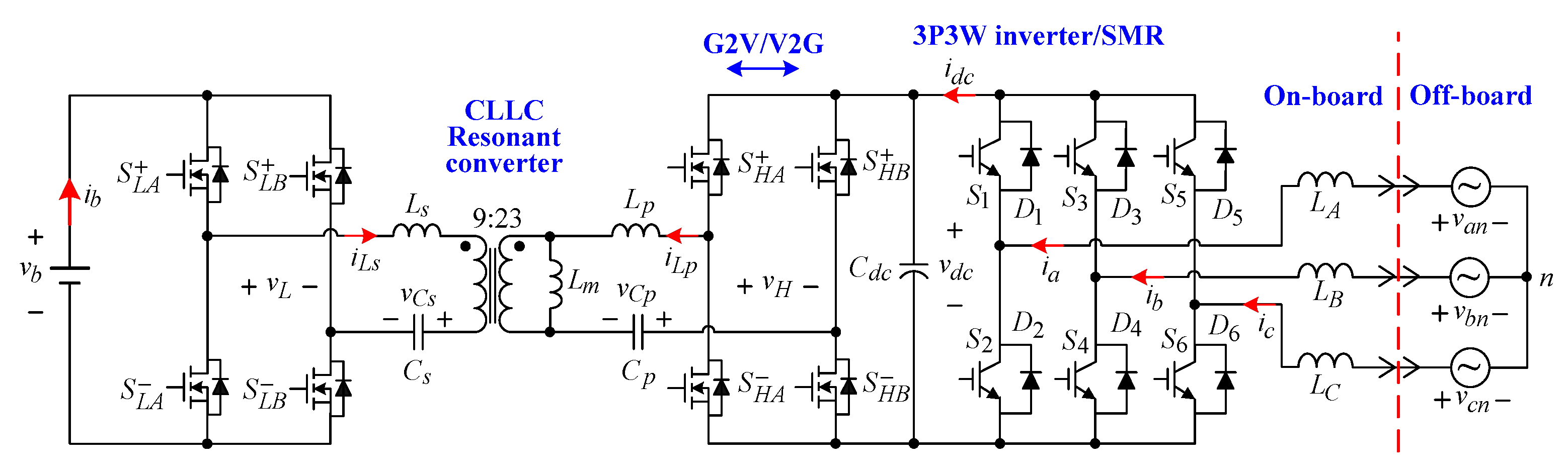
Figure 19.
Measured results of developed inverter in G2V mode under constant current charging: (a) from the grid; (b) of the CLLC resonant converter; (c) .
Figure 19.
Measured results of developed inverter in G2V mode under constant current charging: (a) from the grid; (b) of the CLLC resonant converter; (c) .
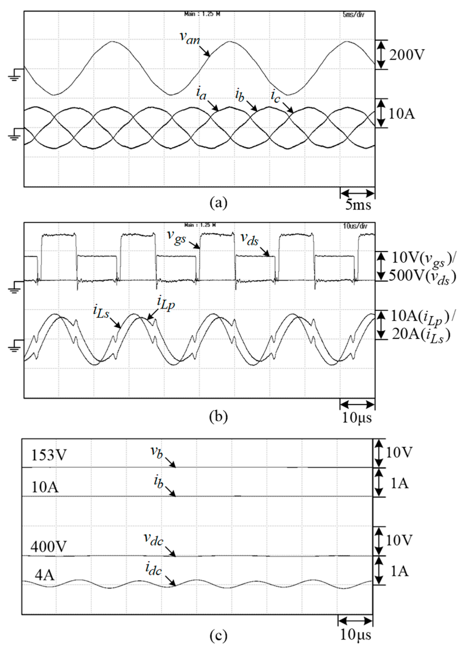
Figure 20.
Measured results of developed inverter in G2V mode under constant voltage charging: (a) from the grid; (b) of the CLLC resonant converter; (c) .
Figure 20.
Measured results of developed inverter in G2V mode under constant voltage charging: (a) from the grid; (b) of the CLLC resonant converter; (c) .

Figure 21.
Measured results of developed inverter in V2G mode under steady state at : (a) of the CLLC resonant converter; (b) ; (c) from the grid.
Figure 21.
Measured results of developed inverter in V2G mode under steady state at : (a) of the CLLC resonant converter; (b) ; (c) from the grid.
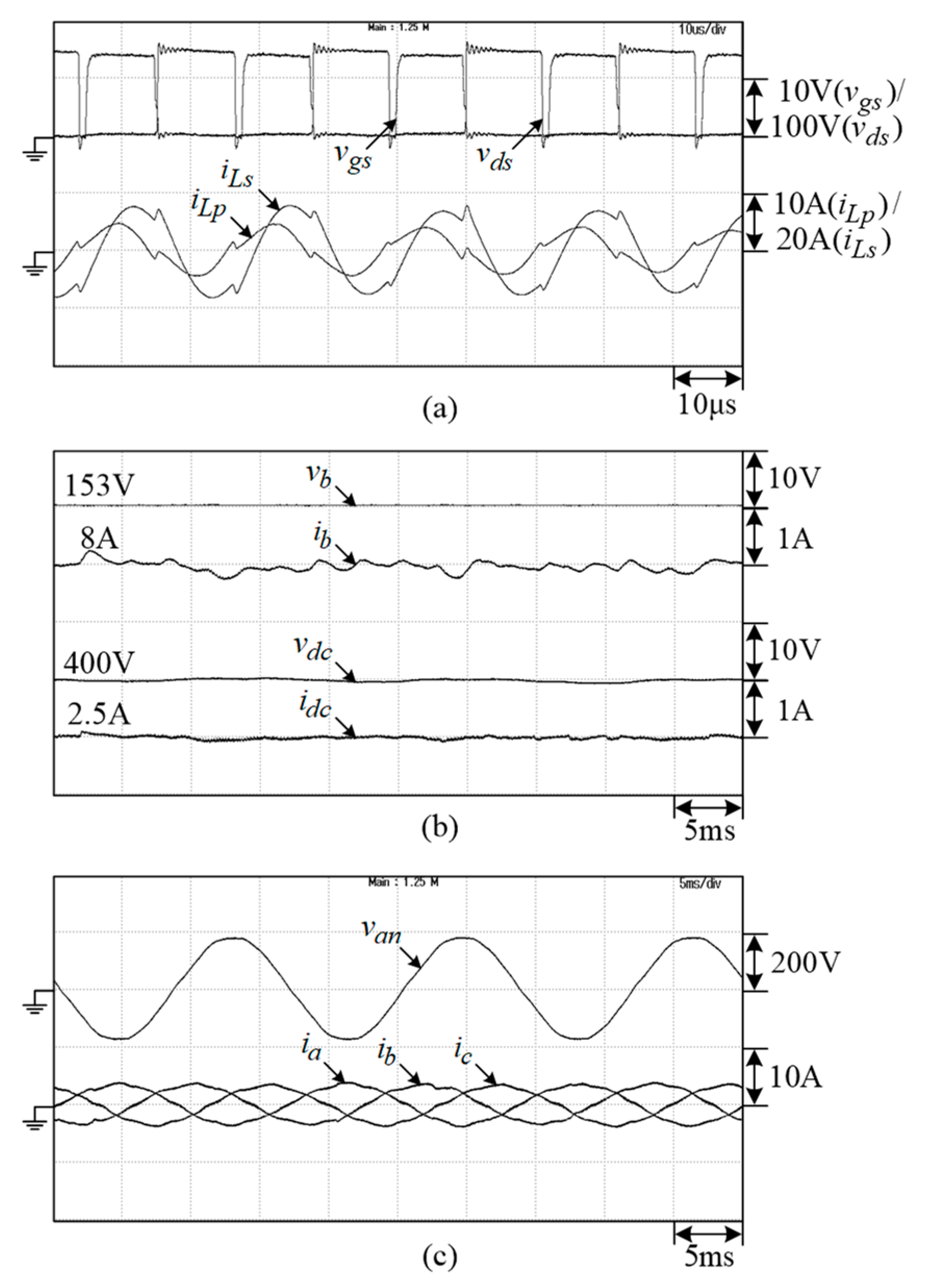
Figure 22.
Measured results of developed inverter in V2G mode under steady state at : (a) of the CLLC resonant converter; (b) ; (c) from the grid.
Figure 22.
Measured results of developed inverter in V2G mode under steady state at : (a) of the CLLC resonant converter; (b) ; (c) from the grid.
Figure 23.
Measured results of developed inverter in V2G mode under steady state at : (a) of the CLLC resonant converter; (b) ; (c) from the grid.
Figure 23.
Measured results of developed inverter in V2G mode under steady state at : (a) of the CLLC resonant converter; (b) ; (c) from the grid.
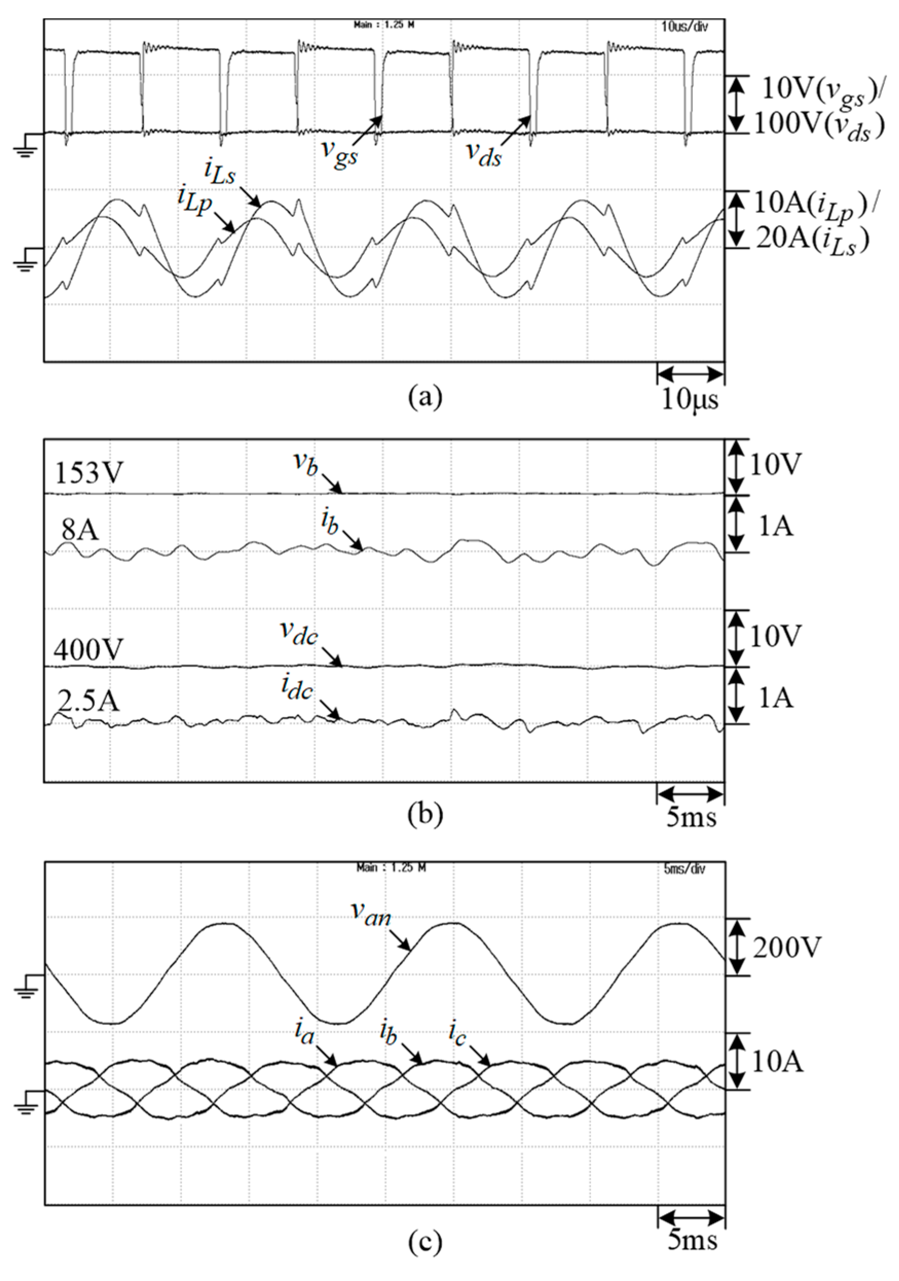
Figure 24.
System configuration of developed V2V scheme.

Figure 25.
Detailed power circuit of developed V2V scheme.

Figure 26.
CLLC resonant converter control scheme of EV2 in developed V2V scheme.

Figure 27.
Measured steady state and of developed V2V scheme under charging current command .

Figure 28.
Measured , and of developed V2V scheme under charging current command change .
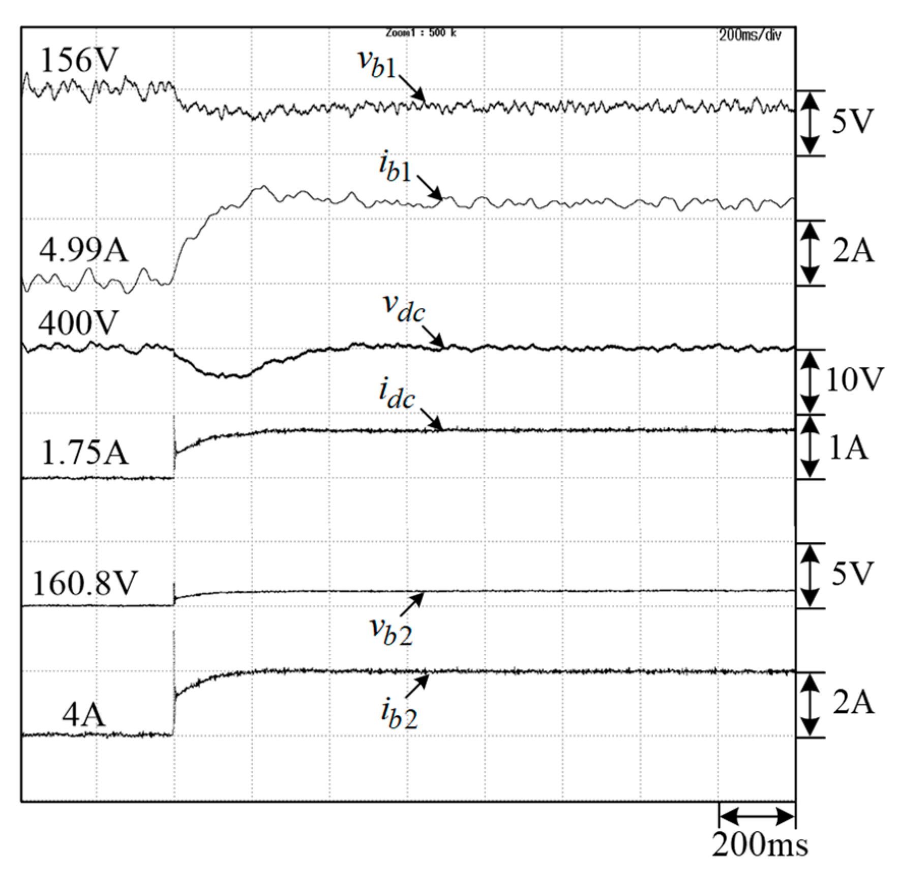
Figure 29.
Measured and of developed V2V scheme under preset charging current command pattern .
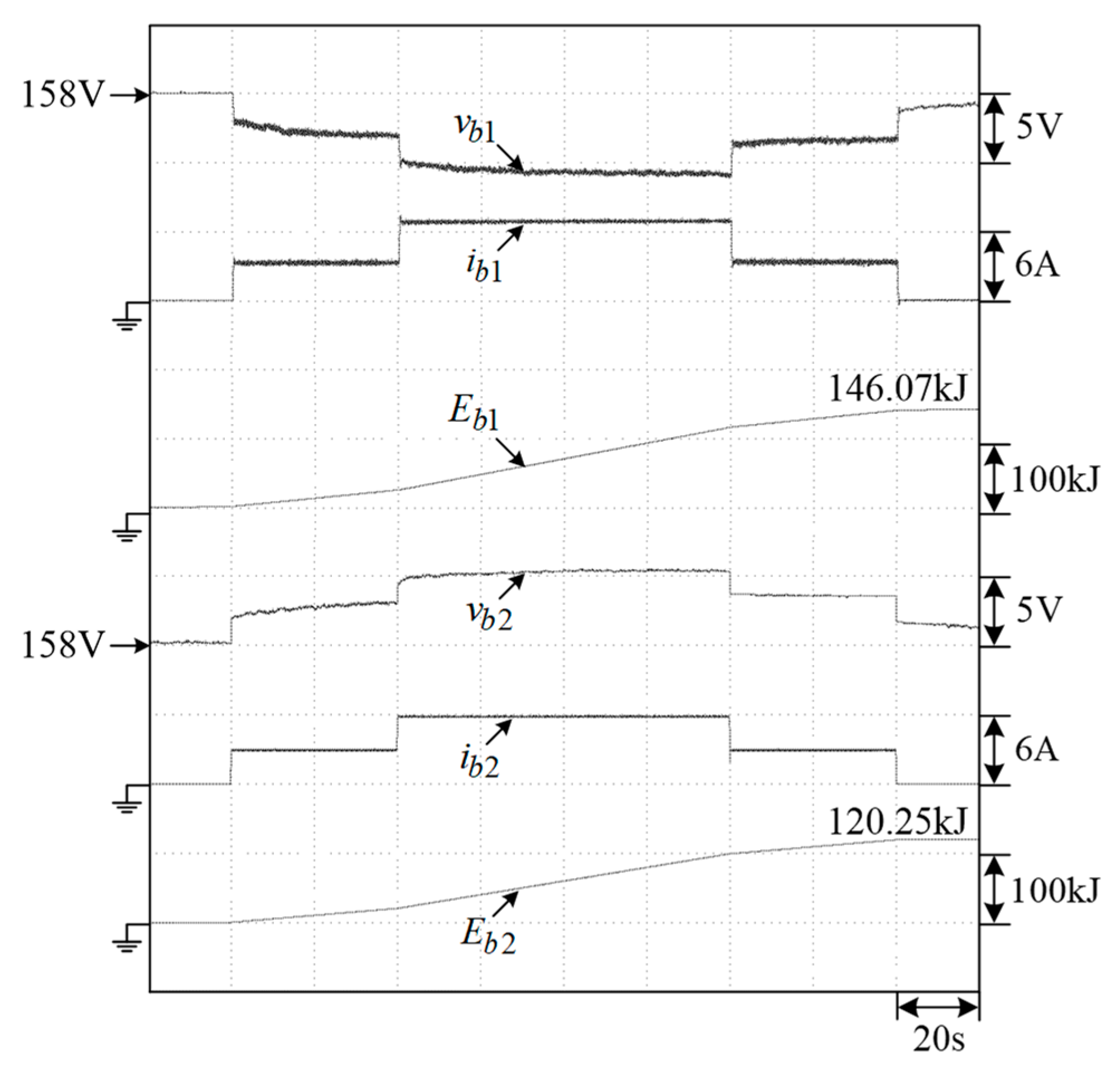
Figure 30.
System configuration of developed M2V/V2M operations.

Figure 31.
Detailed power circuit of developed M2V/V2M operations.

Figure 32.
Measured results of M2V operation under charging power : (a) of DC microgrid system; (b) of CLLC resonant converter; (c) of EV onboard battery.
Figure 32.
Measured results of M2V operation under charging power : (a) of DC microgrid system; (b) of CLLC resonant converter; (c) of EV onboard battery.
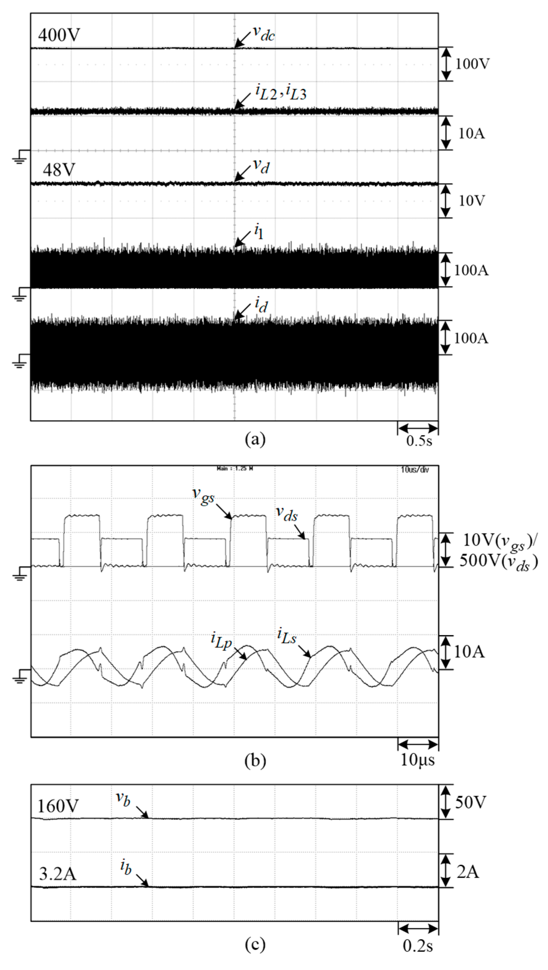
Figure 33.
Measured results of V2M operation under DC load power and battery charging power : (a) of EV battery; (b) of CLLC resonant converter; (c) of battery in DC microgrid.
Figure 33.
Measured results of V2M operation under DC load power and battery charging power : (a) of EV battery; (b) of CLLC resonant converter; (c) of battery in DC microgrid.

Disclaimer/Publisher’s Note: The statements, opinions and data contained in all publications are solely those of the individual author(s) and contributor(s) and not of MDPI and/or the editor(s). MDPI and/or the editor(s) disclaim responsibility for any injury to people or property resulting from any ideas, methods, instructions or products referred to in the content. |
© 2024 by the authors. Licensee MDPI, Basel, Switzerland. This article is an open access article distributed under the terms and conditions of the Creative Commons Attribution (CC BY) license (https://creativecommons.org/licenses/by/4.0/).
Share and Cite
MDPI and ACS Style
Gu, W.-K.; Yang, C.-W.; Liaw, C.-M. An EV SRM Drive and Its Interconnected Operations Integrated into Grid, Microgrid, and Vehicle. Appl. Sci. 2024, 14, 3032. https://doi.org/10.3390/app14073032
AMA Style
Gu W-K, Yang C-W, Liaw C-M. An EV SRM Drive and Its Interconnected Operations Integrated into Grid, Microgrid, and Vehicle. Applied Sciences. 2024; 14(7):3032. https://doi.org/10.3390/app14073032
Chicago/Turabian StyleGu, Wei-Kai, Chen-Wei Yang, and Chang-Ming Liaw. 2024. "An EV SRM Drive and Its Interconnected Operations Integrated into Grid, Microgrid, and Vehicle" Applied Sciences 14, no. 7: 3032. https://doi.org/10.3390/app14073032
Note that from the first issue of 2016, this journal uses article numbers instead of page numbers. See further details here.