Article

Acoustic Emission Monitoring in Prestressed Concrete: A Comparative Study of Signal Attenuation from Wire Breaks and Rebound Hammer Impulses

1
Marx Krontal Partner (MKP GmbH), Zum Hospitalgraben 2/2a, 99425 Weimar, Germany
2
Institut für Massivbau, Technische Universität Dresden, 01219 Dresden, Germany
*
Author to whom correspondence should be addressed.
Appl. Sci. 2024, 14(7), 3045; https://doi.org/10.3390/app14073045
Submission received: 18 March 2024 / Revised: 29 March 2024 / Accepted: 30 March 2024 / Published: 4 April 2024

Abstract

:
Acoustic emission monitoring (AEM) has emerged as an effective technique for detecting wire breaks resulting from, e.g., stress corrosion cracking, and its application on prestressed concrete bridges is increasing. The success of this monitoring measure depends crucially on a carefully designed sensor layout. For this, the attenuation of elastic waves within the structure’s material is ideally determined in situ through object-related measurements (ORMs) with a reproducible signal source, typically a rebound hammer. This assumes that the attenuation coefficients derived from rebound hammer tests are comparable to those from wire breaks, thus allowing their results to be directly applied to wire break detection without further adjustments. This study challenges this assumption by analysing attenuation behaviour through an extensive dataset. Employing time-domain and frequency analysis, the research generates attenuation profiles from laboratory experiments and in situ measurements across various girders and bridge structures, extracting the slope and residual standard deviation (RSD). While generally validating this approach, the findings highlight differences in attenuation behaviour from among wire break signals and rebound hammer impulses, whereby the latter potentially underestimates the relevant attenuation of wire breaks by approximately 20%. Consequently, a transfer factor is proposed to adjust ORM results obtained with the rebound hammer for wire break scenarios. It consists of a scaling factor of 1.2 to modify the average attenuation coefficient and a constant term of ±1.0 dB/m to cover a 95% confidence interval, and thus, account for sample scattering. Moreover, the anisotropic attenuation behaviour across different structures was studied, showing that transverse attenuation consistently exceeds the longitudinal, significantly influenced by structural features such as voids. In prefabricated concrete bridges with in situ-cast concrete slabs, transverse signal transmission remains unhindered across multiple elements. Finally, the results provide a valuable reference for the design of sensor layouts in bridge monitoring, particularly benefiting scenarios where direct in situ experiences are lacking.

1. Introduction

In its transportation infrastructure, a significant portion of Germany’s bridges were constructed using prestressed concrete. In particular, bridges built in the 1950s and 1960s are now operating close to their load-bearing limits due to increased traffic demands. Of particular concern are prestressed concrete bridges made with prestressing steel, which is prone to stress corrosion cracking, where sudden failure is possible under certain conditions [1,2,3]. To compensate for potential structural deficiencies resulting from the gradual failure of prestressing steel, targeted monitoring is essential. Acoustic emission monitoring (AEM) has proven to be an effective method for detecting wire breaks and is increasingly being applied in the construction industry [4,5,6,7]. Furthermore, this method can be applied not only to prestressed concrete bridges, but also to monitor damage to cables in suspension and cable-stayed bridges [8,9,10,11].
The implementation of AEM in civil engineering is mostly non-standardized, and the application of this measurement technique requires specialized expertise. This often results in contractors having difficulty verifying or evaluating the technical specifications or measurement data for plausibility. Moreover, the uniqueness of each bridge in terms of its construction and its specific loading and environmental conditions necessitates a tailored assessment approach. In combination, these aspects contribute to considerable variability in the execution and quality of technical solutions. In this context, the Acoustic Emission Testing Committee of the German Society for Non-Destructive Testing (DGZfP) recently published guideline SE05, providing a detailed instruction manual for AEM implementation in Germany. This guideline consolidates best practices, establishes fundamental aspects, and offers a procedural guide for projects [12].
For the successful implementation of AEM, a carefully designed sensor layout for the affected structure is essential. This layout must enable the detection of wire breaks with sufficient reliability and is one of the most important prerequisites for the success of the monitoring. The design is based on three central input parameters:
  • the characteristics and intensity of the source signal;
  • the material- or structure-specific attenuation;
  • the intensity of the background noise to define the detection threshold.
The determination of the source characteristics of a wire break is usually based on experience, as comprehensive studies on this topic are rare. A contribution to this topic is the database mentioned in [13], which analyses a variety of events and serves also as a basis for this study. The determination of attenuation and background noise is ideally carried out directly on the structure through object-related measurements (ORMs). For this, several measurement series are recorded with an artificial, reproducible signal source to obtain attenuation profiles and determine attenuation coefficients. The rebound hammer is often used as a reference source for this purpose [13,14], which generates a strong impact on the concrete surface since its impulse on the structure is necessarily very energetic. This standardised instrument enables reliable reproduction at almost any location on the structure.
Despite the successful application of this method in determining the required input parameters for designing a sensor layout, there are significant differences among the source mechanisms of a wire break and the excitation by the rebound hammer to be considered. While a wire break causes signal generation longitudinally to the axis of the tendon inside the construction, the excitation by the rebound hammer occurs on the concrete surface and, as such, orthogonally to the axis of the tendon; see Figure 1. This difference must be considered when transferring the measurement results to the specific issue of wire break detection using AEM.
Measurements conducted with the rebound hammer on bridges or other large structures are documented in [14,15,16,17,18]. In some of these studies, wire breaks were intentionally generated to compare signal characteristics. Similarities were observed between the signals from rebound hammer impacts and those generated by wire breaks. The corresponding attenuation coefficients, determined based on the peak amplitudes of the measured signals, ranged from 2.6 to 7.0 dB/m. These studies primarily used sensors operating in the frequency spectrum below 200 kHz; a tabular overview of the results can be found in [18]. However, these studies focused mostly on one specific test object, with attenuation not being the central focus of investigation. A comparison between the signal sources, considering a variety of specimens and a comprehensive dataset of individual events, both from rebound hammer impacts and wire breaks has, thus far, not been feasible due to these limitations.
This research specifically addresses the need for detailed comparative analyses between rebound hammer impacts and wire breaks. By generating both types of events on various girders and structures, a comprehensive real-world database was created. The aim of this analysis was to identify the similarities and differences in the attenuation of the two signal sources and to evaluate their transferability. Hence, not only typical time-domain features such as peak amplitude and signal energy were considered, but frequency domains were analysed as well to cover frequency-dependent effects. Additionally, the propagation behaviour of the signals in both the longitudinal and transverse directions was investigated. Special attention was paid to structural transitions and joints in prefabricated constructions and their influence on wave propagation. The results were processed in a way that statistically derived and validated design parameters for AEM. These are particularly relevant when ORMs, as recommended in [12], are not possible before implementation of the monitoring devices. This might be the case due to lack of expertise on the contractor side or due to time constraints, e.g., in case of particular urgency or imminent danger. In such instances, the insights from this study provide a solid foundation to rely on qualified empirical knowledge and ensure the reliability of the monitoring as well.

2. Acoustic Emission and Attenuation of Elastic Waves in Concrete Constructions

Acoustic emission (AE) refers to the phenomenon whereby waves are generated and propagate elastically within a material, such as during the formation of cracks. The dynamic deformations appearing on a structure’s surface can be detected via piezoelectric sensors, thereby facilitating the monitoring of material changes and structural integrity. To analyse the underlying phenomena, the measured time-amplitude signals are typically reduced to a few characteristic features in either the time or frequency domain. Notably, these features include the peak amplitude A peak and energy E, as highlighted in [19]. The propagation of elastic waves is subject to attenuation effects, which must be considered in the design of measurement campaigns and the evaluation of results. Geometric attenuation, for instance, results in a decrease in the source impulse’s energy, as the wavefront expands with increasing distance r. For spherical waves, the sound intensity I and the sound level A can be expressed with
I 1 r 2 and A 1 r ( spherical waves )
and for cylindrical waves with
I 1 r and A 1 r ( cylindrical waves )
Considering just the geometric part, the decrease in sound intensity or sound level decreases by 6 dB for spherical waves and 3 dB for cylindrical waves with each doubling of distance from the source. In contrast, plane wavefronts remain unaffected by geometric attenuation. Furthermore, along the propagation path, both sound intensity and level are reduced due to scattering, reflection, and absorption. For describing dispersive attenuation, the application of an exponential decay function is appropriate:
I I 0 e α · r and L L 0 e α · r ,
where α is the material- and frequency-dependent attenuation coefficient. Due to the heterogeneous composition, the attenuation behaviour of elastic waves in concrete is quite complex. On the mesoscale, the material composition is important, which is why aggregates, pores, and reinforcement have so often been addressed in investigations [20,21,22,23,24,25]. Experiments have predominantly been conducted on small-scale specimens to describe the relationship between signal amplitudes and propagation distances, quantified through attenuation coefficients. A pronounced frequency-dependent attenuation of amplitude, correlated with the concrete’s composition, has been observed consistently. Philippidis et al. investigated small cubic concrete specimens with 150 mm edges and found that attenuation increases linearly below 100 kHz, from approximately 10 dB/m at 10 kHz to 200 dB/m at 100 kHz, and then ascends slightly to between 230 and 400 dB/m at 1 MHz [24]. However, this study did not consider the effects of partial reflections at the specimen-transducer interface or diffraction loss. Addressing these factors, Treiber et al. demonstrated that both partial reflections and diffraction losses generally lead to an overestimation of attenuation coefficients, particularly highlighting the dominant effect of reflection losses over diffraction [26]. In cement paste, attenuation estimates extended up to 6 MHz, showing an attenuation coefficient of about 140 dB/m at 1 MHz. Ono’s investigations into mortar samples revealed attenuation coefficients in the range of 220–250 dB/m at 1 MHz [27,28]. Further studies explored the influence of void content on mortar’s attenuation coefficient, indicating increases in attenuation with greater void content. These analyses primarily revealed a linear relationship between attenuation coefficient and frequency within the attenuation spectra.
The frequency dependency extends to other signal characteristics, such as the signal’s energy [29,30]. The interplay between the wavelength and the size of the scatterer is critical; attenuation is markedly reduced when the wavelength exceeds the dimensions of the concrete’s components or scatterers. Consequently, it has been proposed that interpreting signals in concrete at frequencies above 200 kHz presents significant challenges [20].
At the structural level, the propagation of elastic waves is significantly influenced by the presence of reinforcement bars and prestressing tendons, primarily due to the superior signal transmission capabilities of steel and the anisotropic arrangement of these elements, which serve as waveguides within the concrete matrix [31,32]. It has been particularly noted that attenuation along prestressing wires in grouted ducts is higher compared to that of exposed wires [33,34], a phenomenon attributed to energy dissipation through emission across the interface into the grout and surrounding concrete. Moreover, the wave propagation characteristics are also affected by the prestressing of the concrete. To explain, it has been observed that prestressed concrete members demonstrate lower attenuation levels in comparison to their reinforced concrete counterparts [35], which can be attributed to the prestressing of the concrete, which tends to close existing cracks. A comparison of damaged and undamaged reinforced concrete structures, as shown in [36], supports the idea that damage increases attenuation. Simply put, higher attenuation was observed in damaged structures. It is suspected that especially in areas with disturbances, Rayleigh waves, which transport the highest energy, do not transmit effectively [37].
These principles are relevant to the interpretation of the data and are taken into account in their interpretation. Furthermore, the data preparation in Section 3.3 is based on these explanations.

3. Materials and Methods

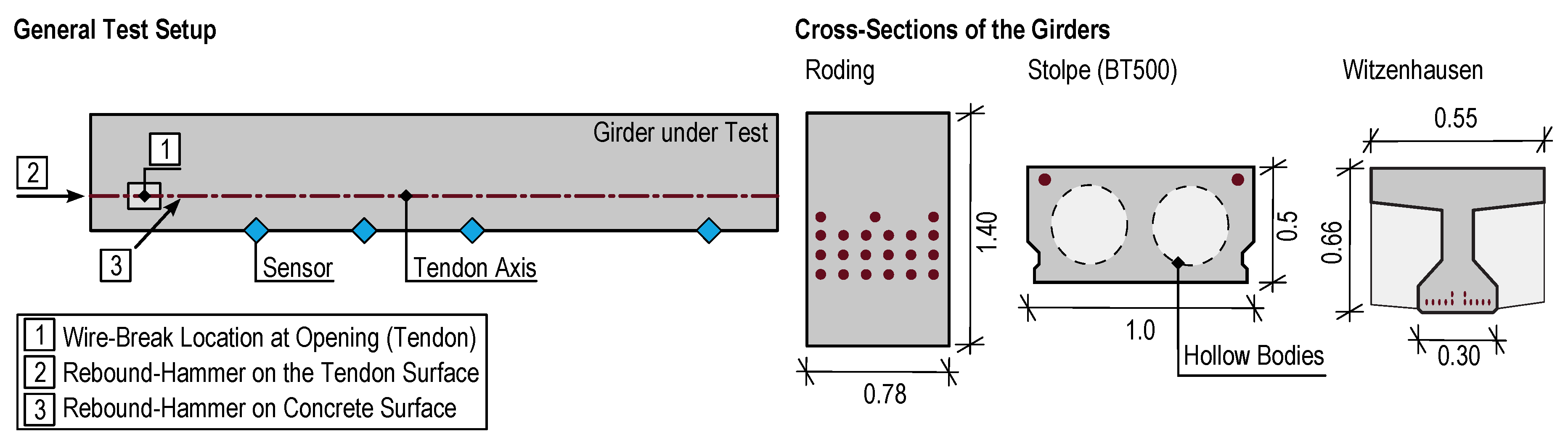
3.1. Experiments on Bridge Girders under Laboratory Conditions

Wire breaks are rarely measured under real-world conditions and are at best artificially provoked in a limited number in investigations on operating structures. However, for this research a total of six girders were sourced from three bridges at risk from stress corrosion cracking during their dismantling and then destructively tested. These girders were predominantly in an undamaged state. Detailed descriptions of the girders and documentation of these experiments are available in [13,18]. Briefly:
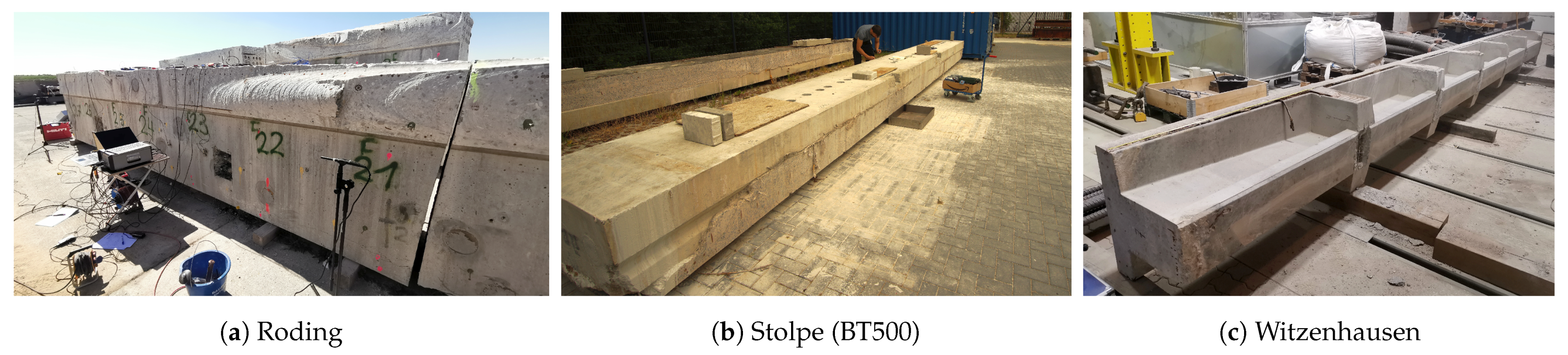
  • Girders of a box girder bridge near Roding:
    The bridge was built in 1965 near the city of Roding. Two web segments, each with a length of 7 m, were obtained; see Figure 2a. The girders examined contained 21 tendons, each with 42 wires.
  • Typified prefabricated post-tensioned girders (BT500) of a bridge near Stolpe:
    The bridge near Stolpe supported an agricultural road over the A24 motorway and was constructed in 1981 from prefabricated elements of the BT500 series with BSG-50 tendons made in the former GDR; see Figure 2b. The lengths of the girders were uniformly 11 m. Each tendon contained 16 wires. The oval prestressing wires are known to be very susceptible to stress corrosion cracking.
  • Prefabricated, prestressed girders from a bridge near Witzenhausen:
    The third pair of girders was obtained during the dismantling of a side road over a railway track; see Figure 2c. The prefabricated elements were produced in 1962, each with a length of 9 m. Each girder contained 12 ribbed, oval wires. Compared to the specimens from the other bridges, the girders of the Witzenhausen bridge were less massive, with a profiled cross-section.
Measurements on each girder followed a consistent methodology, as depicted in Figure 3. Initially, the tendons or wires were exposed in specific areas, where individual wires were then cut. Sensors were positioned along the longitudinal axis of each tendon, aligned with the site of the wire break location. Subsequently, depending on accessibility, either in the vicinity of this opening or at the ends of the girders, rebound hammer impulses were generated directly on the prestressed steel; see also Figure 3. It was ensured that the integrity of the tendon was preserved to avoid affecting signal propagation by having introduced separations. These measurements allowed for the direct comparison of signals from both sources given their identical direction of action. However, the rebound hammer impulses were also generated on the concrete surface to ensure the measurements’ applicability and comparability with ORMs conducted on actual structures. The number of measured signals is detailed in Table 1.
For the experiments, an AMSY-6 measurement system and VS30-V sensors with a flat frequency response ranging from 25 to 80 kHz from Vallen Systeme GmbH (Wolfratshausen, Germany) were used [38,39]. The AMSY-6 system’s analogue, high-pass filter was set to a cutoff frequency of 0.5 kHz. No further analogue or digital filtering was applied. Capturing wire break and rebound hammer signals poses a challenge due to the high energy of the source signal. When too close to the source, the input level on the measuring device could be surpassed, necessitating the hardware configuration of the measurement chain to attenuate the signals purposefully for recording. To this end, special attenuators were employed, achieving effective attenuation levels of −20 and −40 dB. The sampling rate was 1 MHz. The time-amplitude signal is recorded on the basis of a fixed threshold. A signal is recorded as soon as the threshold is crossed and a time-based detection criterion (hit-definition time) is not exceeded between two consecutive threshold crossings. Consequently, the duration of a signal is influenced by its intensity.

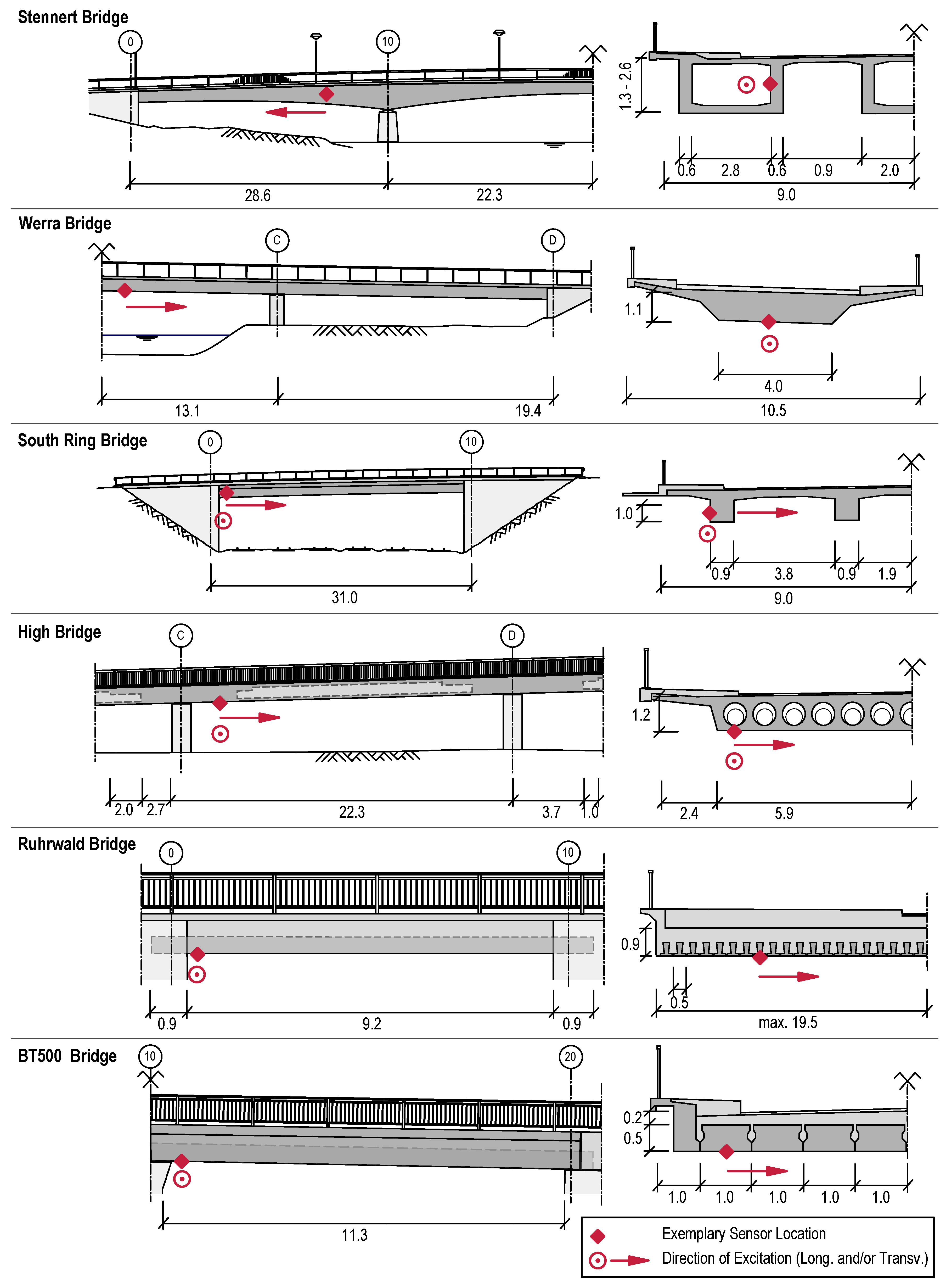
3.2. Measurements on Bridges In Situ

The investigations conducted on the girders were enhanced with measurements on a variety of existing structures using the rebound hammer to ensure the transferability of the wire break results from the girders to real structures and to obtain additional reference values for designing the sensor layout. These structures differed notably in terms of their construction and geometrical dimensions, as shown in Figure 4 and elaborated on in the following descriptions:
  • Stennert Bridge, Hagen:
    The Stennert Bridge in Hagen-Hohenlimburg crosses the federal road B7 over the Lenne River and has a total length of 102.70 m. The load is supported by three hollow boxes connected through the roadway slab. The bridge was constructed in 1959, and the prestressing steel used is classified as particularly susceptible to stress corrosion cracking. Despite its age the structure is generally in good condition, free from cracks, and suitable for targeted monitoring. In 2018, an AEM system was installed, with sensors placed laterally on the 50 cm thick webs.
  • Werra Bridge, Walldorf:
    The Werra Bridge was built in the 1980s as a three-span, prestressed concrete structure with a total length of 64.90 m along state road L2624. The structure exhibits damage in various areas in the form of cracking, caused by an alkali–silica reaction (ASR) leading to expansive mineral formation. Material investigations revealed that the superstructure was constructed using prestressing steel susceptible to stress corrosion cracking. To ensure the ongoing operation of the structure, an AEM system was installed in 2021. Additionally, regular visual inspections are conducted.
  • South Ring Bridge, Leer:
    This bridge carries a local road over the railway line Rheine–Emden (track 2831). The superstructure was constructed in 1969 as a single-span beam with a span of 31.70 m. The cross-section is a four-web T-beam with a construction height of approximately 1.45 m. The four main girders of the superstructure are prestressed longitudinally. Due to material-specific issues with the prestressing steel and structural shortcomings, the structure was equipped with a monitoring system in 2020.
  • High Bridge, Wismar:
    The High Bridge, part of federal road B105, was constructed in 1970 as a multi-span reinforced concrete slab bridge with hollow bodies. The bridge consists of 15 spans with lengths of 22.0 m and 28.0 m (total length 396.0 m). It was prestressed using BSG 25 and BSG 100 tendons made of Hennigsdorfer prestressing steel, which is known to be susceptible to stress corrosion cracking. Static deficits were only identified in two fields, which have been monitored since 2023.
  • Ruhrwald Bridge, Dortmund:
    The Ruhrwald Bridge crosses federal road B54 over a double-track railway line in the city of Dortmund. The structure consists of several substructures of different construction years and types. The substructure examined was built in 1957 using post-tensioned, prefabricated concrete elements, which were connected to form a slab with a reinforced concrete topping in situ. The span and width are 9.15 m and 19.45 m, respectively. The prestressing steel used is classified as susceptible to stress corrosion cracking. Computational analysis revealed deficiencies, leading to the installation of an AEM system in 2022.
  • BT500 Bridge, Coswig:
    The bridge carries a state road near an urban area over a railway track and was constructed in 1985 as a prefabricated bridge. It consists of two spans, each of 11.27 m. The superstructure contains 8 post-tensioned prefabricated beams of type BT500N, supplemented with cast-in-place concrete to form a slab. The beam elements were made with Hennigsdorfer prestressing steel. Corrosion pits were found on the steel during material investigations, attributed to stress corrosion cracking. Structural deficits prompted an ORM to assess the applicability of an AEM system on the bridge.
The in situ measurements on the bridges were executed either through distinct campaigns or during the installation of a permanent monitoring system. Contrary to the girder measurements, where the signal emission originated from a stationary point, the in situ measurements featured variable signal emission locations. The structure was gradually “tapped” at predetermined intervals. The source of the signal was a rebound hammer, identical to the one employed in the destructive tests detailed in Section 3.1. To achieve adequate statistical reliability, multiple impacts from the rebound hammer were applied at each signal emission location.
Figure 4 depicts one example sensor position and the directions of investigation for each structure. This information was subsequently utilized to generate the attenuation profiles. For some structures the measurements were conducted throughout the entire structure, involving multiple sensor positions. While multiple sensors were analysed, not all are depicted in Figure 4 to maintain clarity within the figure. Nonetheless, the quantity of measured signals and attenuation profiles is documented in Table 1.
In every instance, the AMSY-6 measurement system from Vallen Systeme GmbH, paired with VS30-V sensors, was employed [38,39]. The setup required no hardware configuration beyond a preamplification setting of 0 dB. The measurement system’s analogue, high-pass filter was adjusted to a cutoff frequency of 0.5 kHz, with no further analogue or digital filtering applied. This consistent use of measurement technology components and sensors across different tests ensures the reliability and comparability of the measurements conducted on both bridges and beams. The sampling rate was 1 MHz. The time-amplitude signals were recorded using the same procedure as described in Section 3.1.

3.3. Data Processing

The analysis of the measurement data was conducted using two distinct processes, each comprised of multiple steps. First, the time-domain features peak amplitude A peak and energy E were derived. To achieve this, signals were standardized at a preamplification level of 0 dB, and a consistent threshold of 90 dB was established. Following this, both features were calculated directly from the raw data of the time-amplitude signal. The peak amplitude is typically measured in decibels ( d B A E ), whereas energy is calculated over the signal’s duration and is expressed in V 2 · s . For enhanced comparability, the energy was also converted to decibels in this study using the formula
E ( dB ) = 10 · log 10 ( E ( V 2 · s ) ) .
The features were then represented in decibels against the distance between the source and sensor, as illustrated in Section 4. To account for the variance in individual measurements, a 90% confidence interval was depicted as an envelope curve for each feature. In processing the data, the two types of attenuation—geometric and dispersive—could not be distinguished in detail due to insufficient knowledge about their specific contributions to the attenuation observed. Nevertheless, converting the data to a logarithmic scale linearized the exponential function’s appearance, facilitating the determination of the attenuation coefficient through linear regression across the entire range of values, i.e., all distances on the x-axis [21]. Additionally, to enhance the empirical distribution statistically, a bootstrapping method with 1000 iterations per attenuation profile was employed, justified by the adequate size of the original sample set. The regression’s coefficient and the residual standard deviation (RSD) were determined, with the latter calculated as follows:
RSD = i = 1 n ( y i y ^ i ) 2 n 2
where n is the number of observations, y i is the observed, and y ^ i is the predicted value of the dependent variable. The RSD quantifies the spread of the differences between the observed values and those predicted by the model, thus serving as an indicator for evaluating the model’s fit to the data. Both coefficients and RSDs are documented in Section 4. Utilizing these two statistical parameters, the characteristics of the phenomena under investigation were assessed.
In the second process, the focus was on the frequency dependence of attenuation. To this end, signals were normalized to a preamplification level of zero dB. A threshold is generally not required for frequency analysis, but was used with 90 dB to determine the signal onset. The signals were then trimmed to a unified length of 1200 µs with pre- and post-triggers of 200 and 1000 µs, respectively. This segmented signal was then processed, resampling at 10 MHz and applying a Hanning window to mitigate leakage effects, before being transformed into the frequency domain with Fourier transformation. To investigate the frequency dependence of attenuation, the resulting frequency spectrum was segmented into partial frequency bands, each 10 kHz wide, spanning from 0 to 100 kHz, as illustrated in Figure 5a. The investigation’s upper frequency limit was set at 100 kHz. This was based on the observation that the frequency spectra of the measured signals from both signal sources show a significant decrease within the 70 to 100 kHz range, already evident near the source location (approximately 0.3 m), as depicted in Figure 5. The subsequent increase between 115 and 120 kHz remains below the amplitudes noted in the range of 10 to 60 kHz and is, therefore, excluded from the evaluation, presumably resulting from a harmonic of the sensor’s resonance frequency, around 60 kHz. For each of the delineated partial frequency bands, the mean spectral amplitude was calculated. These calculations served as the basis for creating the attenuation profiles shown in Section 4. In this section, a representative curve for each structure is displayed, regardless of the number of sensors analysed. The mean amplitudes were plotted against the distance between the signal source and sensor, similarly to the previous time-domain features. For the frequency bands extending up to 50 kHz, the attenuation coefficients and the RSDs were determined using linear regression and subsequently documented in Section 4. The analysis again utilized bootstrapping to expand the sample size.
The resulting statistical parameters from the regressions of both processing approaches were finally transformed into box plots to illustrate the statistical trends and variations in Section 5. The data processing was conducted using self-written programs in PyCharm Community Editor 2022.1.1 and Python 3.8.6.

4. Results

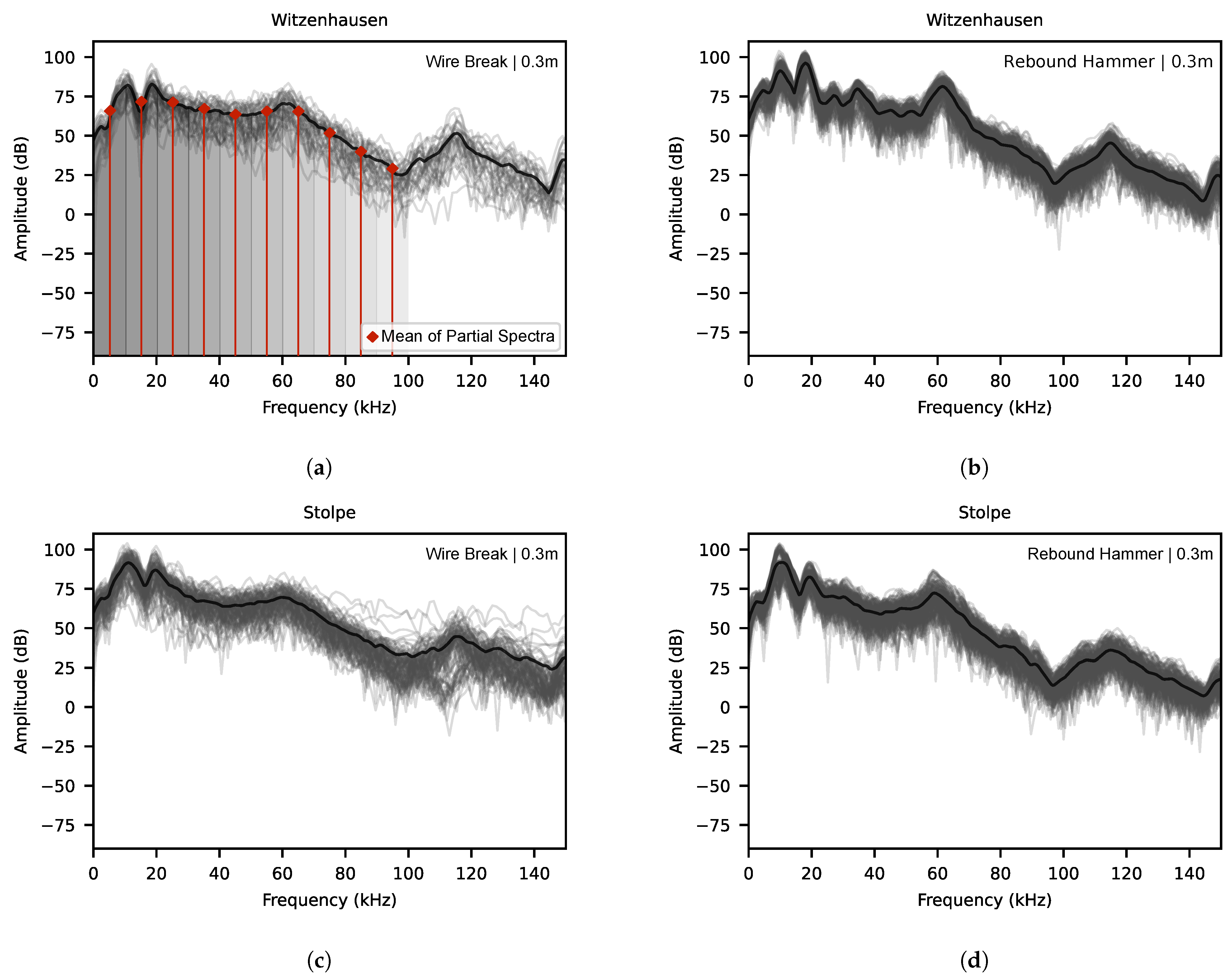
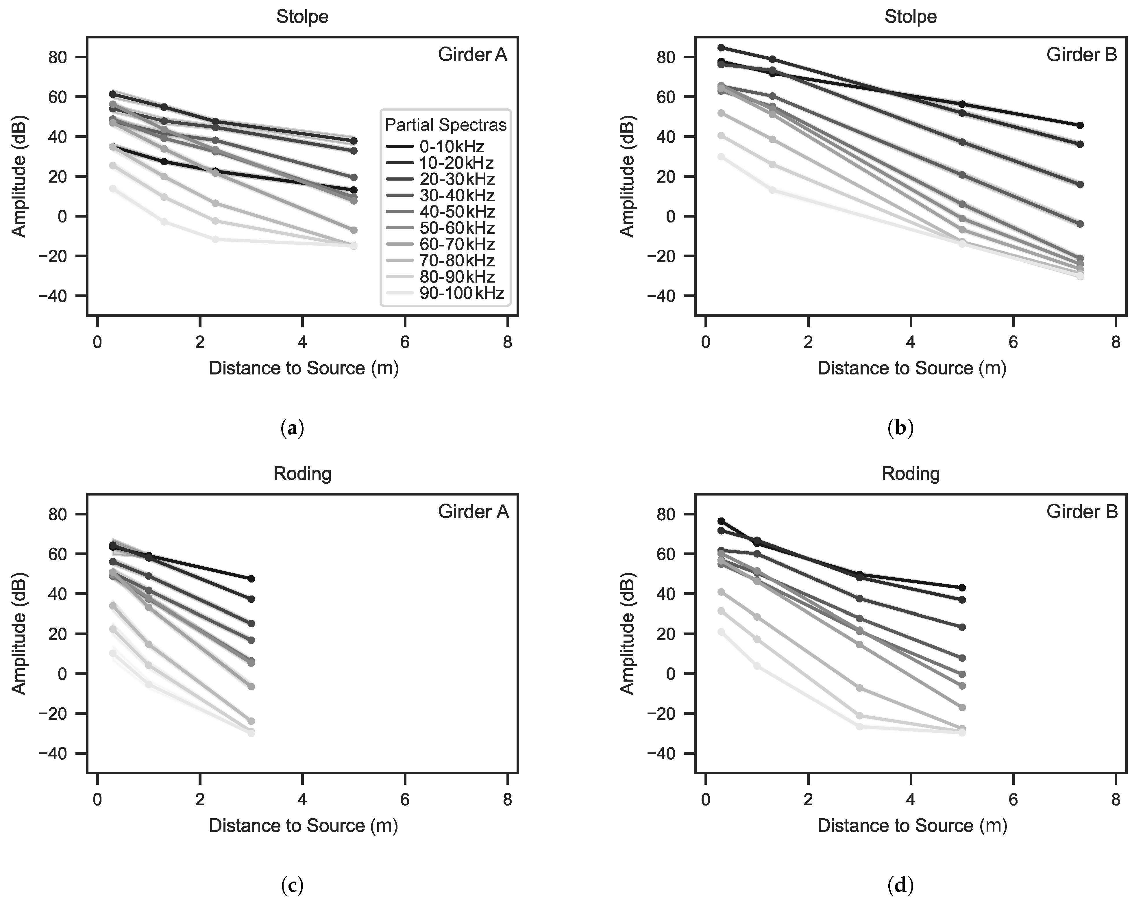
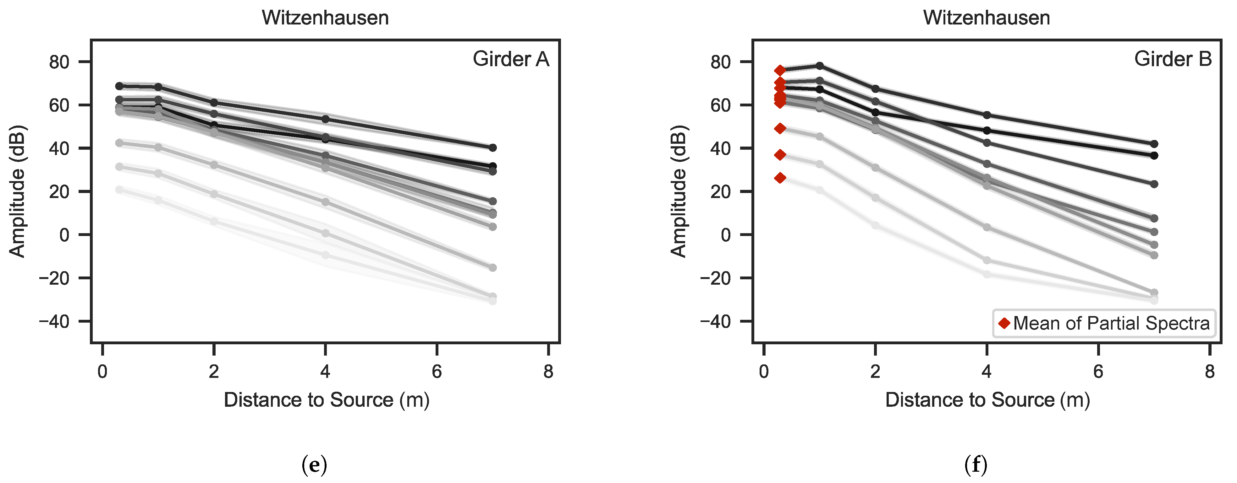
4.1. Wire Breaks on Girders

The wire breaks were generated on the girders from Stolpe, Roding, and Witzenhausen. Figure 5 shows the amplitudes for the frequency bands depending on the distance between the signal source and the sensor. Each girder (A and B) is depicted in a separate subplot. Figure 6 shows the time-domain features. In general, the attenuation profiles presented demonstrate the expected trend, where amplitudes diminish as the distance from the signal source increases. This attenuation is least noticeable at lower frequencies, where the relationship between distance and amplitude reduction can sometimes appear nearly linear. However, with an increase in frequency the amplitudes decline more sharply, leading to nonlinear profiles characterized by a steep decrease in amplitude over distances up to 3 to 4 m. Beyond this point, the slope of the decrease lessens, suggesting that the frequency components have been almost entirely filtered out. This effect varies in magnitude across different girders; for instance, it is clearly visible in the case of girder A from Stolpe, whereas it is less pronounced in girder A from Witzenhausen.
The observation is similarly reflected in the time-domain features. In Figure 7, the plots each represent data from one measurement campaign conducted on one tendon per girder. The nonlinear relationship between the variables is also evident to varying degrees. Despite this nonlinearity, employing linear regression across the full range of the abscissa for calculating the attenuation coefficients is deemed sufficiently precise for each scenario, aligning with standard practices. It is important to acknowledge, however, that this methodology tends, in absolute terms, to overestimate the attenuation coefficient at greater distances.
In Table 2, the attenuation coefficients documented reveal that the girders from Roding exhibit the highest values, indicating a significant increase in attenuation as the frequency rises as well, with girder A being particularly notable. This is partly attributed to the shorter length of the Roding girders, which limited the range of distances between the source and sensor that could be examined. For girder A, it was only possible to measure distances up to approximately 3 m, leading to an overestimation of the attenuation coefficients in this case. Due to this lack of comparability, these values were excluded from the statistical analysis presented in Section 5. Moreover, there is a considerable variation in the cross-sectional dimensions of the girders. The girders from Witzenhausen are characterized by their slender profile in the section of the wires, while the Stolpe girders feature hollow bodies that locally reduce the cross-section, as detailed in [13]. In contrast, the Roding girders are significantly more massive and contain a large number of tendons, which act as major scatterers and contribute to increased attenuation. Nevertheless, the cross-sectional dimensions are likely the critical factor influencing these observations. The geometric dimension of the cross-section becomes apparent once the spherical wavefront originating from the source encounters the component’s surface. In slender components, this occurs after shorter travel distances when compared to more massive components. Subsequently, the wavefront ceases to expand, apart from reflections, and when the curvature of the wavefront decreases, it effectively transforms itself into a planar wave. This phenomenon mitigates the impact of geometric attenuation in slender components. This hypothesis is supported in the analysis of time-domain features, where, with the exception of girder A from Stolpe, the Roding girder demonstrated higher attenuation levels.

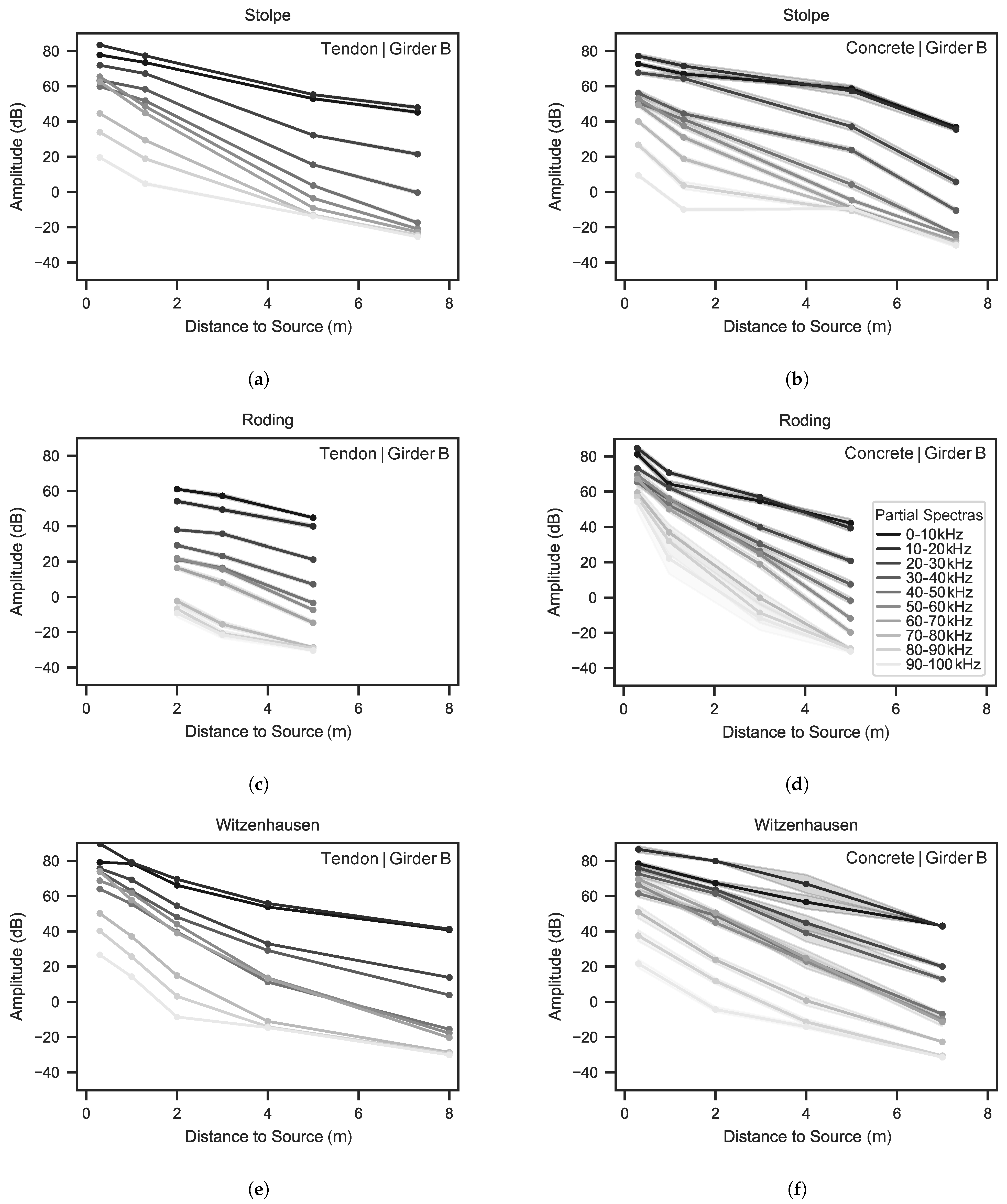
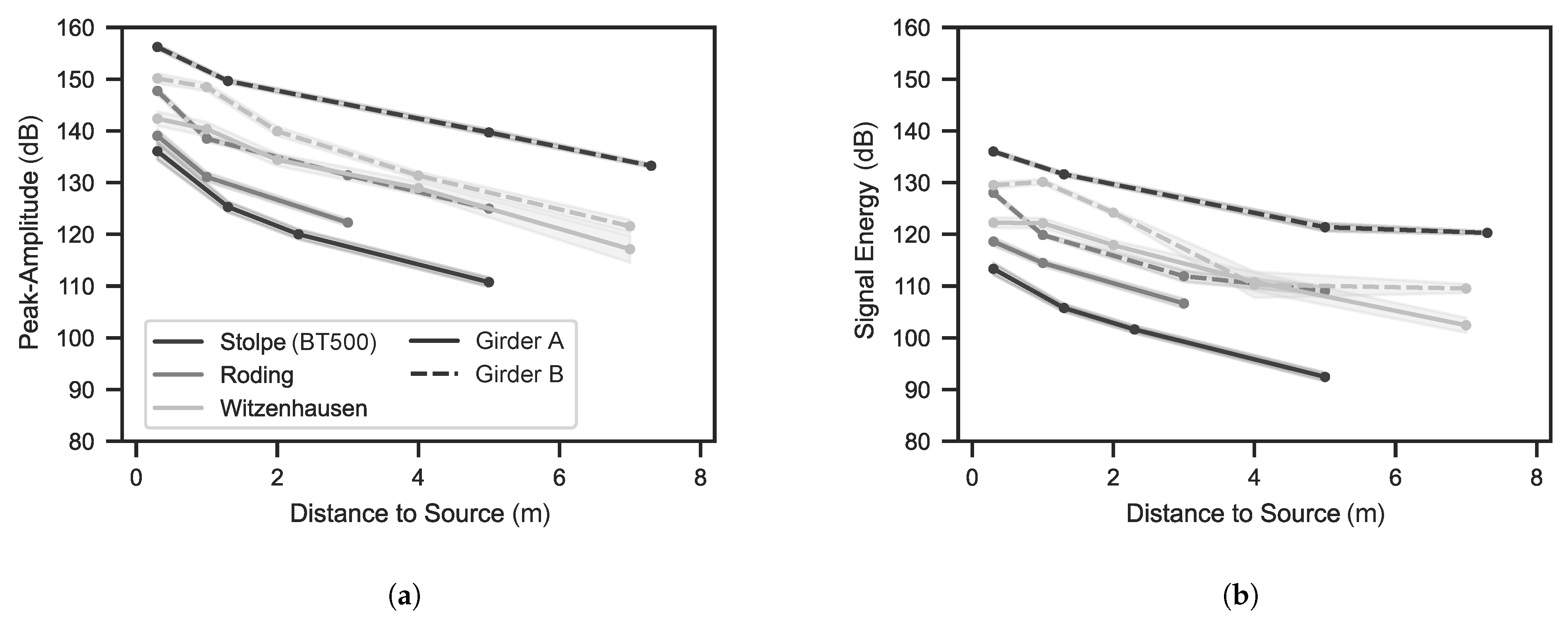
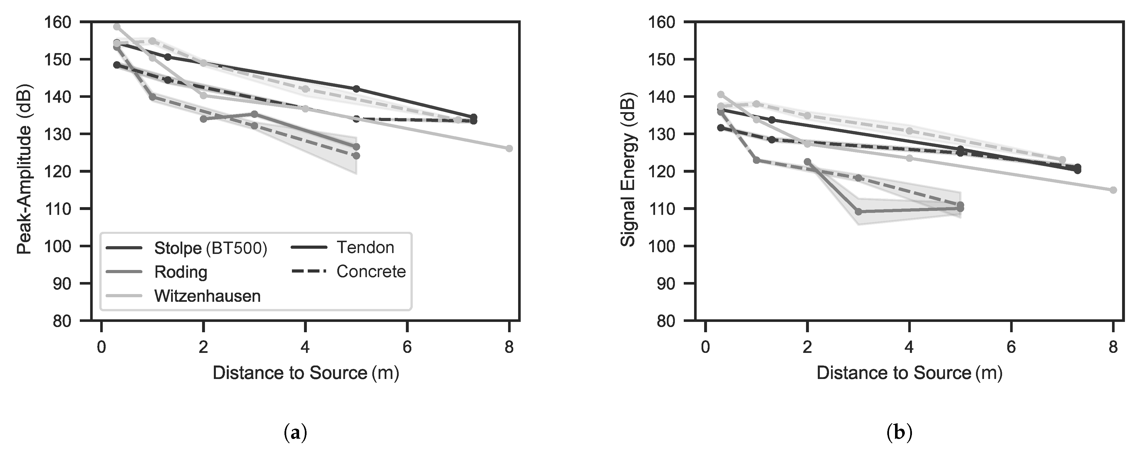
4.2. Rebound Hammer Impacts on Girders

In Figure 8 and Figure 9, the experiments utilizing the rebound hammer on the girders are illustrated. These tests involved generating signals on the concrete surface orthogonal to the tendon axis and at the prestressing steel at locations where the cross-sections of the tendons were accessible. The figures provide a side-by-side comparison of these two signal input methods for the girders B of each structure. Additionally, Table 3 aggregates the statistical parameters derived from these measurements.
The signal profiles resulting from the rebound hammer impulses share general characteristics with those of wire break events, demonstrating similar behaviour in terms of attenuation and signal propagation. Despite these similarities, closer examination also reveals differences in the attenuation coefficients between the two types of sources. Notably for the frequency bands, in some cases signals from rebound hammer impulses tend to exhibit slightly higher attenuation compared to those from wire breaks, e.g., for the Witzenhausen girder. This observation, however, is not confirmed by the analysis of time-domain features, which suggests the opposite for Stolpe and Witzenhausen. This discrepancy might originate from the methodological differences in data processing between the two analyses. Specifically, for the frequency band analysis only the initial part of the signal was considered, focusing on the signal onset for extraction and evaluation. In contrast, the time-domain feature analysis took the entire signal into account. Moreover, the comparison between the two methodologies is inherently constrained due to the composite nature of time-domain features, which superimpose all frequency components without delineating their distinct contributions, notably in the context of peak amplitude. Given the practical importance of time-domain features in assessing attenuation, this feature should be considered as decisive in the analysis.
In the comparison of excitation types with the rebound hammer, the time-domain features for Stolpe and Witzenhausen exhibit higher attenuation coefficients when the excitation is applied to the tendon, thus emphasizing the analogy to wire breaks. Yet the time-domain features reveal the reverse pattern, except for the Roding girder, where the opposite can be observed, and the inversion represents a “safer” scenario for extrapolating results. In this case, the attenuation coefficients obtained with the rebound hammer are higher than those for wire breaks. However, the quality of correlations for this case are the weakest, as illustrated in Figure 9.
These findings highlight that both wire break and rebound hammer excitations exhibit very similar attenuation behaviour, independent of the method of excitation. Nonetheless, it also underscores the complexity in interpreting individual measurements. Consequently, a statistical examination of the data will be undertaken in Section 5 to facilitate a better understanding of how results can be transferred between the two sources based on a broader perspective. This analysis will prioritize time-domain features, reflecting their widespread adoption in both academic and practical applications.

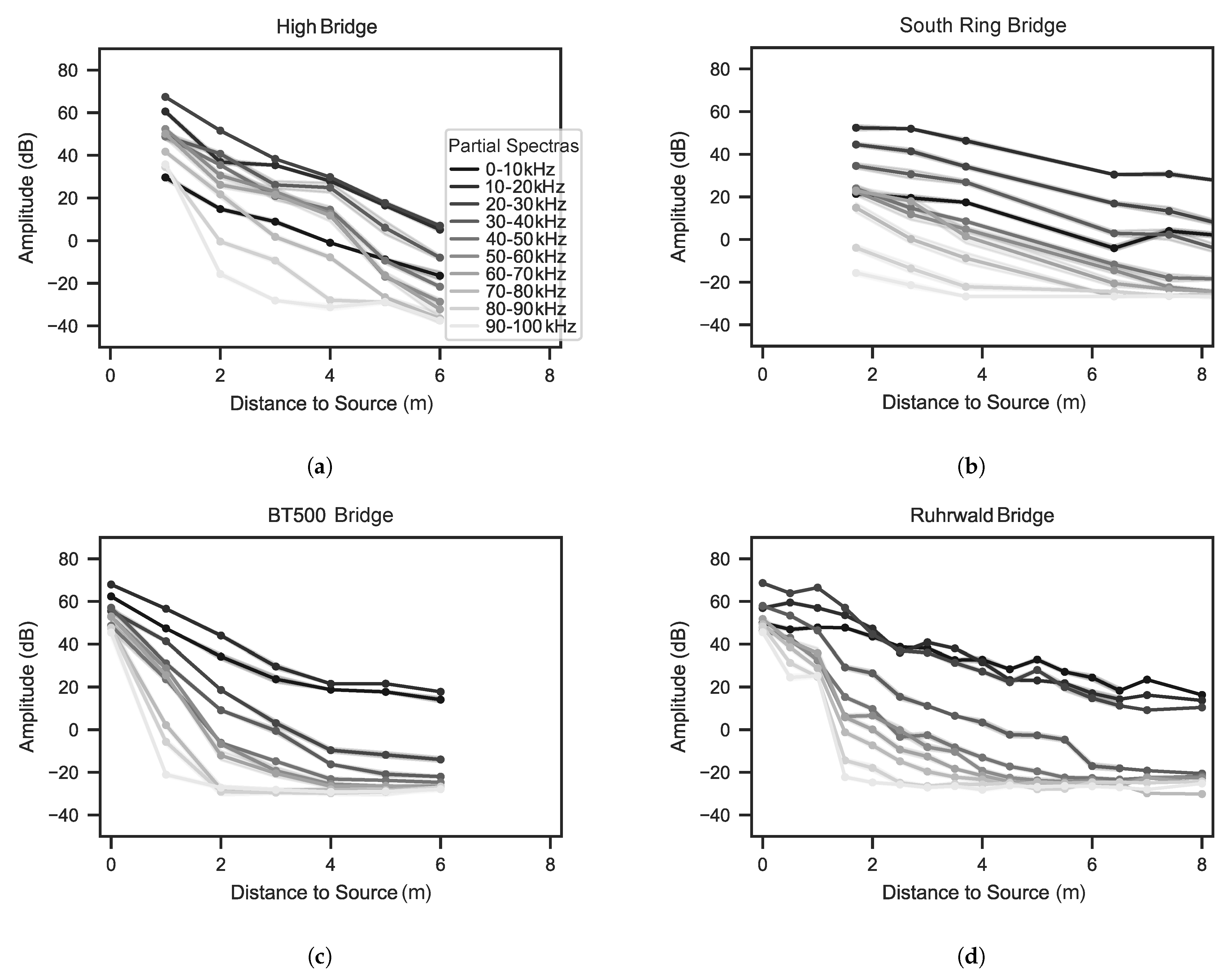
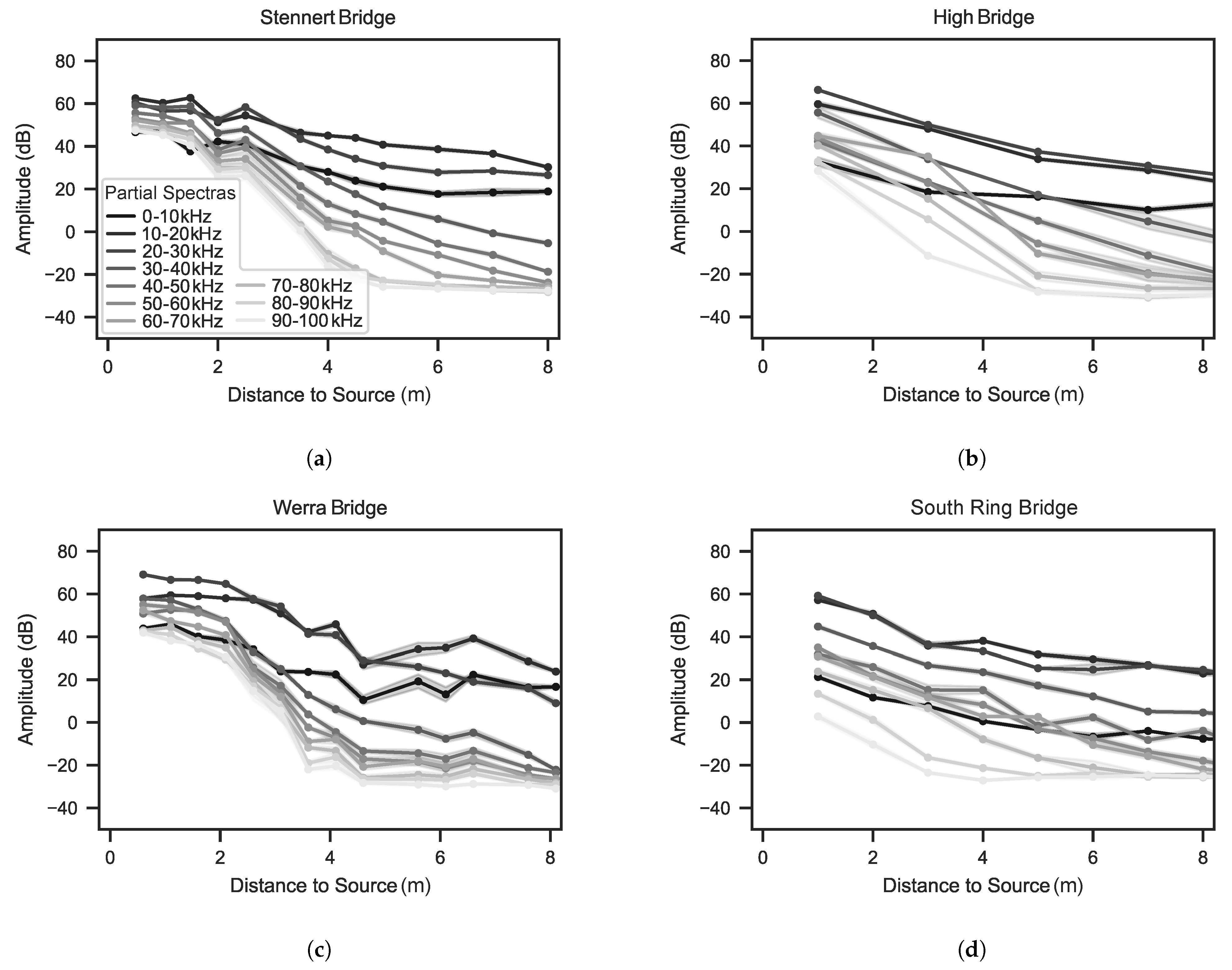
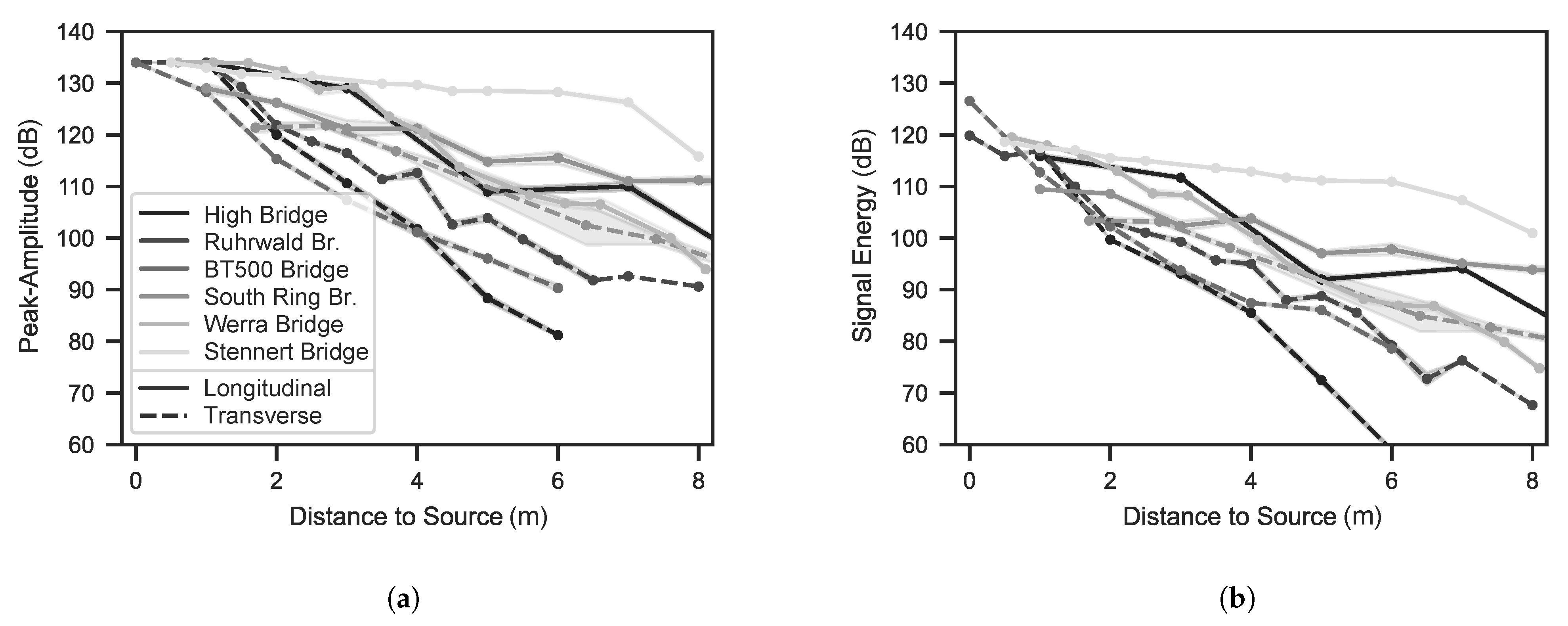
4.3. Rebound Hammer Impacts on Bridges

The girders discussed in Section 4.1 and Section 4.2 may yield signal propagation influenced by effects such as reflections due to their smaller dimensions compared to actual bridges, potentially skewing the assessed attenuation coefficients. To evaluate the findings from these girders further, measurements from six bridges were included. The attenuation was evaluated in both the longitudinal and transverse directions for each of these structures. Figure 10 depicts the frequency-dependent attenuation profiles for the structures in the longitudinal direction, while Figure 11 shows them in the transverse direction. Each structure is represented by a sensor’s characteristic profile, even when multiple datasets were available; see Table 1. Figure 12 presents the time-domain features for both directions of analysis, with coefficients and RSDs detailed in Table 4.
Compared to the girders’ profiles, it is notable that in the bridge measurements the initial amplitudes across different frequency bands resemble each other more than those observed in the girder measurements; see Figure 8, concrete surface. This distribution pattern is somewhat mirrored in the case of girder B from the Roding bridge; see Figure 8d. Given that the Roding bridge’s girders were more heavily reinforced than the others, it suggests that the increased reinforcement and the proximity of tendons to the surface contribute to the reduced attenuation of high-frequency components. Along the bridges’ longitudinal measurements, such as on the web, reinforcement such as tendons was also present. Similarly, the transverse profiles of the BT500 Bridge and Ruhrwald Bridge, measured in the load-bearing areas, which are characterized by significant reinforcement due to shear loads and the anchorage of the tendons, exhibited comparable patterns, as depicted in Figure 10.
Moreover, the attenuation profiles in Figure 10 align with prior observations, showing significant attenuation of high-frequency components up to 50 kHz within a spread of approximately 3 m from the source to the sensor, in contrast to a much lesser decrease observed for low frequencies. Notably, at distances of around 5 to 6 m from the source, the amplitudes for frequencies below 30 to 40 kHz begin to increase again in the Werra Bridge and in the High Bridge. This phenomenon may be attributed to the structural design and variations in reinforcement configuration along the structure’s length, both of which influence signal pathways. Additionally, it is remarkable that the pre-existing damage to the Werra Bridge’s concrete due to ASR manifests only minor differences in the frequency range analysis when compared to the Stennert Bridge; yet a more pronounced correlation is observed in the time-domain features. This highlights the challenges associated with individual assessments and underscores the necessity of performing detailed statistical analysis with particular emphasis on time-domain features, as outlined in Section 5.
The attenuation anisotropy is examined by means of three examples, each containing results in both the longitudinal and transverse directions. For the South Ring Bridge, the directional difference in attenuation is surprisingly small, with the transverse attenuation being at most 30% greater than the longitudinal, as depicted in the time-domain features of Table 4. This may be attributed to the sensor’s placement on the side surface of the main girder, unlike the positioning on the underside with other bridges. At the High Bridge, transverse attenuation is roughly twice that of the longitudinal direction. The presence of hollow bodies within the slab, contributing to enhanced wave scattering, is likely a significant factor in such increased attenuation. Furthermore, combining the results from the Stolpe’s BT500 girder and the BT500 Bridge—owing to their use of identical prefabricated elements—reveals a pronounced increase in transverse attenuation over longitudinal. Time-domain features indicate that the transverse attenuation is about four times greater than the longitudinal. This difference is attributed to the construction. The BT500 Bridge’s slab comprises individual prefabricated elements joined by an in situ concrete layer, elevating the number of construction-related transition zones and challenging the assumption of seamless acoustic coupling between elements. Consequently, for monitoring purposes each prefabricated element might require individual surveillance if minor transmission is possible. The Ruhrwald Bridge, constructed similarly to the BT500 Bridge, also demonstrates evident transverse propagation, supporting the viability of a two-dimensional sensor concept for both structures. Remarkably, both the Ruhrwald and BT500 Bridges exhibit lower attenuation than the High Bridge, underscoring the predominant influence of hollow bodies on attenuation behaviour.

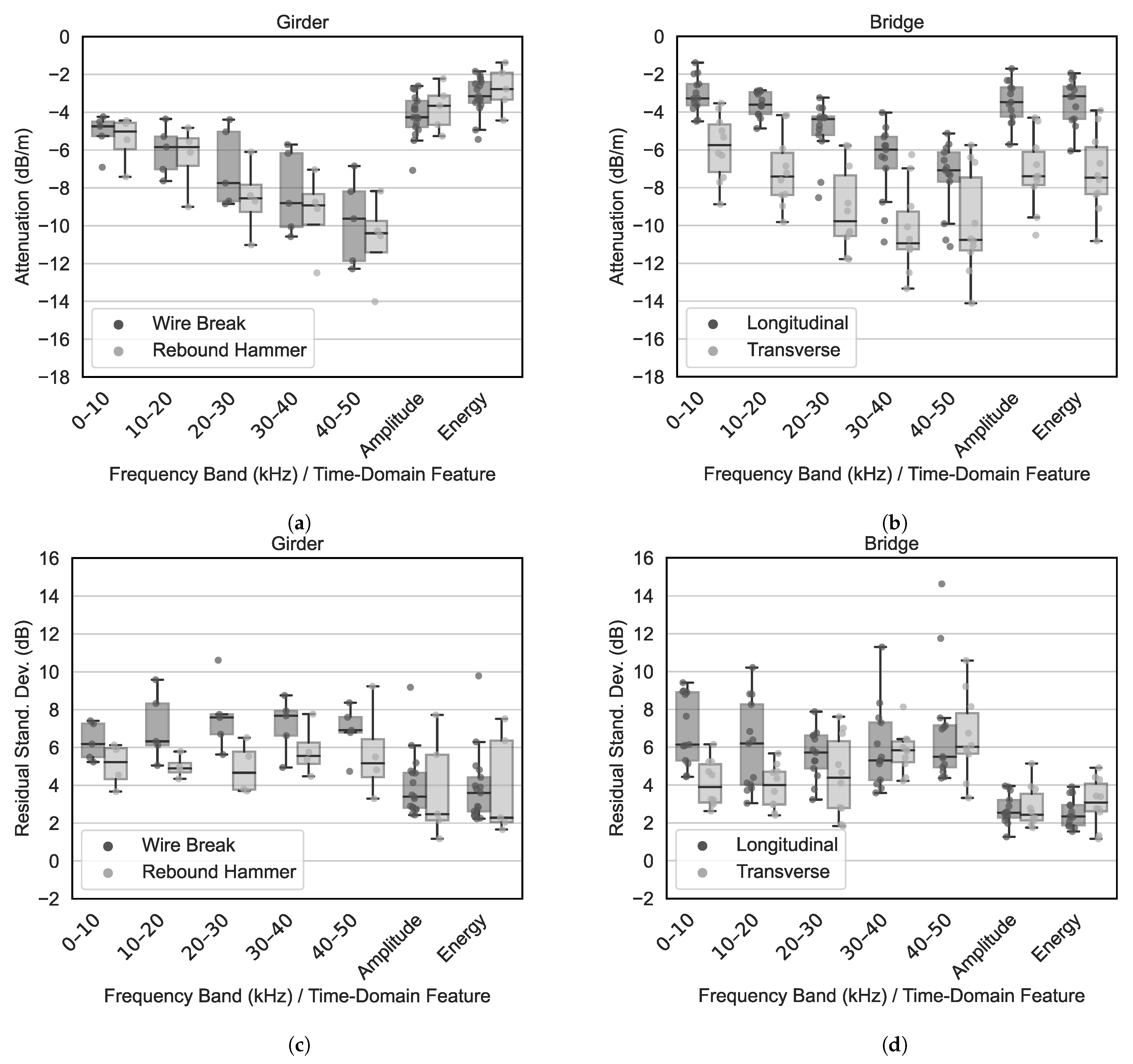
5. Aggregation of Results and Discussion

The attenuation profiles shown in the previous sections, along with the detailed data documentation, already outline initial patterns. To underscore the central tendencies further, a statistical representation of the data through boxplots, as illustrated in Figure 13, is employed, focusing on the evaluation of the medians and RSDs of these distributions. This approach considers the results of wire break and rebound hammer impulses on the girders’ concrete surfaces in addition to all measurements from the bridges.
The analysis is focused on the time-domain features peak amplitude and energy given their practical importance. The medians of the rebound hammer impulses across both girders and bridges range between approximately −2.8 and −3.6 dB/m, with RSDs in the range of about 2.3 to 2.5 dB. Girders show slightly higher RSDs when compared to bridges. This indicates that the outcomes from both girders and bridges share a fundamental comparability and can be mutually transferred. However, the boxplots reveal a tendency for rebound hammer results from bridges to underestimate the attenuation coefficients observed from wire breaks on girders. Specifically, the median attenuation coefficients from wire breaks, considering both peak amplitude and energy, are consistently lower, despite the bridge coefficient ranges’ covering those from wire breaks. This indicates that attenuation coefficients derived from rebound hammer tests on structures do not lead implicitly to a conservative assumption, especially since one of the sampled structures has pre-existing damage, thus unfavourably affecting the distributions. Furthermore, wire breaks typically show RSDs 1.0 to 1.5 dB higher than those from rebound hammer impulses, a pattern replicated across frequency bands. This difference is attributed to wire breaks being subject to complex conditions, leading to less reproducible signals and, quite naturally, to greater variance. These findings confirm the rebound hammer’s suitability as a reliable test and reference source, capable of yielding consistent outcomes for broad application. Nevertheless, they also underscore the need for an extra safety margin when transferring rebound hammer test results to scenarios involving wire breaks.
Based on the data at hand, a transfer factor is proposed herewith to adjust the results of ORMs to account adequately for wire break events. For this purpose, the attenuation coefficient of the ORM β ¯ orm is scaled by a factor F. To account for the variance in the underlying data, the limits of a 95% confidence interval are introduced, using the standard errors of the coefficients (SEs) associated with the wire break events S E ( β ¯ wb ) :
β ¯ orm = F · β ¯ orm ± 1.96 · S E ( β ¯ wb ) .
The transfer factor is determined using the medians of the attenuation coefficients of the time-domain features for the wire breaks and the rebound hammer measurements on the bridges and is approximately the same for both features:
β ¯ wb β ¯ rbh = 4.3 dB / m 3.6 dB / m = 1.2 .
The standard errors of the coefficients of the wire breaks were determined during the data processing, but were not documented in detail. They range between 0.1 and 0.6 dB/m and are similarly distributed for both time-domain features and frequency bands. To account for the scattering, the 95% quantile value of the standard errors is determined at approximately 0.51 dB/m, resulting in the transfer factor
β ¯ orm = 1.2 · β ¯ orm ± 1.0 ( dB / m ) .
In case ORMs are not feasible, the statistical overview obtained suggests that the attenuation coefficient in the longitudinal direction should be chosen to be at least around 6 dB/m.
Figure 13 underscores the observation that higher frequencies experience significantly greater attenuation than lower frequencies. For wire breaks and rebound hammer impulses on the girders, median values in the 0–10 kHz frequency band range from approximately −4.7 to −5.0 dB/m, increasing to about −10.3 dB/m in the 40–50 kHz band. This trend is consistent across bridges in both the longitudinal and transverse directions, suggesting a clear preference for focusing measurements within the low-frequency range. The results discussed align well with the observations made by other researchers, as mentioned briefly in Section 2. Specifically, Ono reported attenuation coefficients in the range of 220–250 dB/m at 1 MHz for mortar specimens, with a predominantly linear relationship observed within the attenuation spectra [27,28]. Based on these findings, it’s feasible to make an approximate extrapolation to the lower frequency range, which is the focus of this study. From this extrapolation, attenuation coefficients are estimated to be between 11.0 and 12.5 dB/m at a frequency of 50 kHz, demonstrating a reasonably good consistency with the established data.
Notably, on the girders, the attenuation coefficients derived from time-domain features generally exhibit lower medians compared to those from frequency bands. For bridges there is an overlap between these two data sets for both types of excitation sources. As discussed in Section 4.2, this discrepancy is likely attributable to the data processing approach, wherein only the signal’s onset was cut for frequency band analysis, and less than the entire transient was used. This could allow for larger-amplitude occurrences in the residual part of the transient, thus affecting the analysis’ outcome.
The validity of the results presented assumes that the sensors utilized in the respective applications have similar sensitivity compared to those employed in this study. It is essential that the sensors’ response spectra predominantly cover frequencies below 100 kHz. Moreover, when calculating attenuation coefficients using regression analysis, the trend in amplitude changes is crucial. In certain instances, particularly at larger distances during rebound hammer tests on bridges, nonlinear relationships were observed. Such nonlinearity can lead to distortions and potential underestimation of the attenuation coefficients, necessitating careful consideration and evaluation in specific applications. Additionally, it is important to acknowledge that the bridges were not uniformly represented in the study. The number of attenuation profiles assessed for each structure varied, as outlined in Table 1. Nonetheless, given the relatively low RSDs and scattering for the more pertinent time-domain features, the dataset is considered to be representative and reliable for the scope of this analysis; see Figure 13d.
In this analysis the material properties of the concrete were not investigated further although it is known that they influence wave propagation and exhibit significant fluctuations. However, the material properties were not experimentally determined for all structures, which is why the data-driven approach was chosen here. Furthermore, except for the Werra Bridge, an undamaged condition of the girders and bridges is assumed. The individual conditions appeared to be good, and the surfaces were free of cracks. However, it cannot with absolute certainty be ruled out that there were internal defects and pre-existing (internal) damage which may have affected attenuation.

6. Conclusions

Acoustic emission monitoring has become a standard practice for monitoring prestressed concrete bridges, particularly for the detection of wire breaks caused by stress corrosion cracking. The success of such monitoring measures crucially depends on a properly designed sensor layout tailored to the specific structure to ensure the detection of all relevant damage signals with high probability. The understanding of the propagation of elastic waves within the structure, especially their attenuation characteristics, is fundamental in this context. Typically, the essential knowledge required for effective monitoring are derived from in situ, object-related measurements (ORMs) on the bridge under investigation using a reproducible reference source, such as the rebound hammer. This approach assumes that the signal characteristics generated by the rebound hammer are analogous to those of wire breaks, allowing for the direct application of the findings from ORMs to the issue of wire break detection without additional modifications. This study challenged this assumption by providing a comprehensive analysis of the attenuation behaviour of impulsive, energetic source events within large prestressed concrete structures, enabling a critical evaluation and comparison based on an extensive dataset.
The research involved conducting experiments on various test objects to generate the data. First, six girders from three different bridges were subjected to controlled destruction in a laboratory setting. These girders underwent artificial wire breaks followed by comparative rebound hammer tests. The rebound hammer introduced impulses both longitudinally into the tendons’ cross-section and orthogonally onto the concrete surface, evaluating the directionality of signal propagation. To complement these laboratory experiments, additional measurements were carried out on six in-service bridge structures, each varying in geometric dimensions and the extent of pre-existing damage. Notably, one of these structures exhibited signs of damage due to alkali–silica reaction, a condition that affects the integrity of concrete due to cracks, whereas the others did not display any significant or otherwise known damage. The combination of these experiments aimed at establishing a transfer factor that could reliably map the rebound hammer impulses to actual wire break events, ensuring the applicability of test results to real-world scenarios.
The analysis covered generating attenuation profiles from the captured signals. This process involved evaluating both classical time-domain features—such as peak-amplitude and energy—and conducting a frequency analysis across ten different frequency bands spanning 0 to 100 kHz. For the time-domain features and the initial 0 to 50 kHz frequency bands, linear regression analysis was applied to interpret the data, which was then statistically parameterized to describe the attenuation characteristics observed. In conclusion, the following aspects can be noted:
  • The results of the girder experiments indicate that attenuation coefficients derived from rebound hammer impulses on the concrete surface generally tended to be lower than those of wire breaks. The observed attenuation coefficients and their RSDs for wire breaks are greater. This is particularly pronounced in the relevant time-domain features, suggesting that the variations are attributable to source-specific causes. Within the frequency bands, a comparable level of attenuation is noted.
  • To adapt the findings from rebound hammer measurements to address wire break scenarios, a transfer factor was established using the data collected from both bridges and girders. This involves a scaling factor of 1.2 to modify the average attenuation coefficient, complemented by a variance of ±1.0 dB/m to incorporate a 95% confidence interval accounting for sample scattering. It is crucial to account for sensor-specific characteristics when implementing this factor.
  • Should ORMs on a structure be impracticable, the results of this research suggest assuming a minimum attenuation coefficient of 6 dB/m for the longitudinal direction of the bridges.
  • The observed scattering in the RSDs from rebound hammer measurements is less than that associated with wire breaks. This suggests that the boundary conditions inherent to wire breaks are naturally complex and result in a higher degree of variance. In contrast, the rebound hammer provides reproducible results, making it an appropriate testing or reference source for this application.
  • Attenuation behaviour exhibits pronounced frequency-dependent effects, with the attenuation coefficient approximately doubling on average from −4.7 to −5.0 dB/m in the 0–10 kHz frequency range to −10.3 dB/m in the 40–50 kHz range. This pattern applies across both beams and bridges and for both types of signal sources. These results quantitatively align with those from other research, indicating a high level of consistency in the measured attenuation coefficients. Frequencies above 50 kHz experience significant attenuation within a distance of approximately 3 to 4 m from the source to the sensor and are largely negligible beyond this range.
  • The analysis of the directionality of attenuation across different structures reveals anisotropic behaviour, where transverse attenuation consistently exceeds longitudinal attenuation. This directional variance is influenced by structural specialities, such as voids and construction joints, as well as sensor orientation, with voids exerting the most significant effect. Notably, in precast concrete bridges with in situ-cast concrete slabs, evidence shows unrestricted signal transmission in the transverse direction across multiple prefabricated elements.
In practical applications, the attenuation coefficients derived from rebound hammer tests offer crucial input for devising sensor layouts for the monitoring of prestressed concrete bridges vulnerable to stress corrosion cracking. The practice of stimulating the concrete surface and extending these findings to address the issue of wire break detection is justified. Nevertheless, it is recommended to incorporate an additional safety margin by applying a transfer factor.
The results documented herein, in conjunction with reference [13], form an important basis for the development of models aimed at quantifying the probability of detection (PoD) for wire breaks in bridges. These models are to be elaborated and discussed in a forthcoming publication.

Author Contributions

Conceptualization, M.K. and S.M.; methodology, M.K.; software, M.K.; validation, M.K. and S.M.; formal analysis, M.K.; investigation, M.K.; resources, M.K.; data curation, M.K.; writing—original draft preparation, M.K.; writing—review and editing, M.K. and S.M.; visualization, M.K.; supervision, S.M.; project administration, S.M.; funding acquisition, S.M. All authors have read and agreed to the published version of the manuscript.

Funding

This research received no external funding.

Institutional Review Board Statement

Not applicable.

Informed Consent Statement

Not applicable.

Data Availability Statement

Data will be made available on request. The data are not publicly available due to privacy.

Acknowledgments

The authors wish to express their gratitude to the municipal and state road authorities for granting permission to utilize the real-world measurement data collected from the bridges.

Conflicts of Interest

The authors declare no conflicts of interest.

Abbreviations

The following abbreviations are used in this manuscript:
AEAcoustic emission
AEMAcoustic emission monitoring
ASRAlkali–silica reaction
ORMsObject-related measurements
RSDResidual standard deviation

References

  1. Nürnberger, U. Analyse und Auswertung von Schadensfällen an Spannstählen; Technical Report, Heft 308; Bundesminister für Verkehr, Abteilung Strassenbau: Bonn-Bad Godesberg, Germany, 1980. [Google Scholar]
  2. Mietz, J.; Fischer, J.; Isecke, B. Spannstahlschäden an einem Brückenbauwerk infolge von Spannungsrißkorrosion. Beton Stahlbetonbau 1998, 93, 195–200. [Google Scholar] [CrossRef]
  3. Hunkeler, F.; Matt, P.; von Matt, U.; Werner, R. Spannglieder, Schrägseile und Anker-Beschreibung der Systeme und Erkenntnisse aus Korrosionsschäden; Technical Report; EMPA, Eidgenössische Materialprüfungs- und Forschungsanstalt: Dübendorf, Switzerland, 2005. [Google Scholar]
  4. Schacht, G.; Käding, M.; Bolle, G.; Marx, S. Konzepte für die Bewertung von Brücken mit Spannungsrisskorrosionsgefahr. Beton Stahlbetonbau 2019, 114, 85–94. [Google Scholar] [CrossRef]
  5. Brandenburg, L.S. B1 Brücke Altstädter Bahnhof, Bauwerksuntersuchungen vor dem Rückbau; Technical Report; Landesbetrieb Staßenwesen Brandenburg: Hoppegarten, Germany, 2021. [Google Scholar]
  6. Sodeikat, C.; Groschup, R.; Knab, F.; Obermeier, P. Acoustic Emission in der Bauwerksüberwachung zur Feststellung von Spannstahlbrüchen. Beton Stahlbetonbau 2019, 114, 707–723. [Google Scholar] [CrossRef]
  7. Löhr, M.; Kleeber, K.; Saloga, K. Überwachung auf Spanndrahtbrüche an der Elsenbrücke in Berlin mittels der Schallemissionsanalyse (AT). ZfP-Zeitung 2022, 178, 30–34. [Google Scholar]
  8. Rymsza, J.; Lacidogna, G. Causes of the Collapse of the Polcevera Viaduct in Genoa, Italy. Appl. Sci. 2021, 11, 8098. [Google Scholar] [CrossRef]
  9. Grabe, M.; Ullerich, C.; Wenner, M.; Herbrand, M. smartBridge Hamburg—Prototypische Pilotierung eines digitalen Zwillings. Bautechnik 2020, 97, 118–125. [Google Scholar] [CrossRef]
  10. Carlos, M.; Cole, P.; Vahaviolos, J.; Halkyard, T. Acoustic Emission Bridge Inspection/Monitoring Stategies. In Structural Materials Technology IV: An NDT Conference; Technomic Publishing Company, Inc.: Lancaster, PA, USA, 2000; pp. 179–183. [Google Scholar]
  11. Tabatabai, H. Inspection and Maintenance of Bridge Stay Cable Systems; NCHRP Synthesis 353; National Cooperative Research Program; Transportation Research Board: Washington, DC, USA, 2005; p. 75. [Google Scholar]
  12. Pirskawetz, S. Richtlinie “Detektion von Spanndrahtbrüchen mit Schallemission”. In Schall 23-Entwicklung und Anwendung der Schallemissionsanalyse und Zustandsüberwachung mit geführten Wellen; Deutsche Gesellschaft für zerstörungsfreie Prüfung (DGZfP): Wetzlar, Germany, 2023; pp. 1–4. [Google Scholar]
  13. Käding, M.; Schacht, G.; Marx, S. Acoustic Emission Analysis of a Comprehensive Database of Wire-Breaks in Prestressed Concrete Girders. Eng. Struct. 2022, 270, 114846. [Google Scholar] [CrossRef]
  14. Pirskawetz, S.M.; Schmidt, S. Detection of Wire Breaks in Prestressed Concrete Bridges by Acoustic Emission Analysis. Dev. Built Environ. 2023, 14, 100151. [Google Scholar] [CrossRef]
  15. Yuyama, S.; Yokoyama, K.; Niitani, K.; Ohtsu, M.; Uomoto, T. Detection and Evaluation of Failures in High-Strength Tendon of Prestressed Concrete Bridges by Acoustic Emission. Constr. Build. Mater. 2007, 21, 491–500. [Google Scholar] [CrossRef]
  16. Fricker, S. Schallemissionsanalyse zur Erfassung von Spanndrahtbrüchen bei Stahlbetonbrücken. Ph.D. Thesis, Eidgenössische Technische Hochschule ETH Zürich, Zürich, Switzerland, 2009. [Google Scholar] [CrossRef]
  17. Oh, T.M.; Kim, M.K.; Lee, J.W.; Kim, H.; Kim, M.J. Experimental Investigation on Effective Distances of Acoustic Emission in Concrete Structures. Appl. Sci. 2020, 10, 6051. [Google Scholar] [CrossRef]
  18. Käding, M.; Schacht, G.; Marx, S. Schallemissionsmonitoring zur Spanndrahtbruchdetektion. In 2023 BetonKalender; John Wiley & Sons, Ltd.: Hoboken, NJ, USA, 2022; Chapter XV; pp. 745–777. [Google Scholar] [CrossRef]
  19. EN 1330-9:2017; Zerstörungsfreie Prüfung-Terminologie-Teil 9: Begriffe der Schallemissionsprüfung. Beuth Verlag GmbH: Berlin, Germany, 2017; p. 15.
  20. Landis, E.N.; Shah, S.P. Frequency-Dependent Stress Wave Attenuation in Cement-Based Materials. J. Eng. Mech. 1995, 121, 737–743. [Google Scholar] [CrossRef]
  21. Köppel, S. Schallemissionsanalyse zur Untersuchung von Stahlbetontragwerken; IBK report Nr. 272; vdf der ETH Zürich: Zürich, Switzerland, 2002. [Google Scholar] [CrossRef]
  22. Ohtsu, M. Source Mechanism and Waveform Analysis of Acoustic Emission in Concrete. J. Acoust. Emiss. 1982, 2, 103–112. [Google Scholar]
  23. Berthelot, J.M.; Souda, M.B.; Robert, J.L. Study of Wave Attenuation in Concrete. J. Mater. Res. 1993, 8, 2344–2353. [Google Scholar] [CrossRef]
  24. Philippidis, T.P.; Aggelis, D.G. Experimental Study of Wave Dispersion and Attenuation in Concrete. Ultrasonics 2005, 43, 584–595. [Google Scholar] [CrossRef] [PubMed]
  25. Schechinger, B. Schallemissionsanalyse zur Überwachung der Schädigung von Stahlbeton; IBK report Nr. 295; vdf der ETH Zürich: Zürich, Switzerland, 2006. [Google Scholar] [CrossRef]
  26. Treiber, M.; Kim, J.-Y.; Laurence, J.J.; Jianmin, Q. Correction for partial reflection in ultrasonic attenuation measurements using contact transducers. J. Acoust. Soc. Am. 2009, 125, 2946–2953. [Google Scholar] [CrossRef]
  27. Ono, K. A Comprehensive Report on Ultrasonic Attenuation of Engineering Materials, Including Metals, Ceramics, Polymers, Fiber-Reinforced Composites, Wood, and Rocks. Appl. Sci. 2020, 10, 2230. [Google Scholar] [CrossRef]
  28. Ono, K. Ultrasonic Attenuation of Ceramic and Inorganic Materials Using the Through-Transmission Method. Appl. Sci. 2022, 12, 13026. [Google Scholar] [CrossRef]
  29. Aggelis, D.G.; Soulioti, D.V.; Sapouridis, N.; Barkoula, N.M.; Paipetis, A.S.; Matikas, T.E. Acoustic Emission Characterization of the Fracture Process in Fibre Reinforced Concrete. Constr. Build. Mater. 2011, 25, 4126–4131. [Google Scholar] [CrossRef]
  30. Wu, X.; Yan, Q.; Hedayat, A.; Wang, X. The Influence Law of Concrete Aggregate Article Size on Acoustic Emission Wave Attenuation. Sci. Rep. 2021, 11, 22685. [Google Scholar] [CrossRef]
  31. Beard, M.D.; Lowe, M.J.S.; Cawley, P. Ultrasonic Guided Waves for Inspection of Grouted Tendons and Bolts. J. Mater. Civ. Eng. 2003, 15, 212–218. [Google Scholar] [CrossRef]
  32. di Scalea, F.L.; Rizzo, P.; Seible, F. Stress Measurement and Defect Detection in Steel Strands by Guided Stress Waves. J. Mater. Civ. Eng. 2003, 15, 219–227. [Google Scholar] [CrossRef]
  33. Li, F.; Huang, L.; Zhang, H.; Yang, T. Attenuation of Acoustic Emission Propagation Along a Steel Strand Embedded in Concrete. KSCE J. Civ. Eng. 2018, 22, 222–230. [Google Scholar] [CrossRef]
  34. Chen, J.; Wan, X.; Guo, Q. Monitoring of Stress Variation of Strands in Prestressed Concrete by Second Harmonic Generation Measurements based on Piezoelectric Sensors. Smart Mater. Struct. 2021, 31, 015004. [Google Scholar] [CrossRef]
  35. Golaski, L.; Gebski, P.; Ono, K. Diagnostics of Reinforced Concrete Bridges. J. Acoust. Emiss. 2002, 20, 83–98. [Google Scholar]
  36. Shiotani, T.; Aggelis, D.G.; Makishima, O. Global Monitoring of Large Concrete Structures Using Acoustic Emission and Ultrasonic Techniques: Case Study. J. Bridge Eng. 2009, 14, 188–192. [Google Scholar] [CrossRef]
  37. Lovejoy, S. Development of Acoustic Emissions Testing Procedures Applicable to Conventionally Reinforced Concrete Deck Girder Bridges Subjected to Diagonal Tension Cracking. Ph.D. Thesis, Oregon State University, Corvallis, OR, USA, 2006. [Google Scholar]
  38. Vallen Systeme GmbH. AE-Sensor Data Sheet VS30-V; Vallen Systeme GmbH: Wolfratshausen, Germany, 2022; Available online: https://www.vallen.de/zdownload/DataSheets/Sensors/VS30-V.pdf (accessed on 29 March 2024).
  39. Vallen Systeme GmbH. AMSY-6 System Specifications; Vallen Systeme GmbH: Wolfratshausen, Germany, 2022; Available online: https://www.vallen.de/zdownload/pdf/AMSY-6_Spec.pdf (accessed on 29 March 2024).
Figure 1. Signal sources under investigation: (a) wire break artificially induced on girders under laboratory conditions; (b) rebound hammer impulses applied longitudinally on the tendons cross-sectional surface; and (c) rebound hammer impulses applied orthogonally to the tendons on the concrete surface.
Applsci 14 03045 g001
Figure 2. Bridge girders tested under laboratory conditions: (a) in situ-cast, post-tensioned element of the web of a hollow box bridge near Roding; (b) prefabricated post-tensioned element (BT500) from a bridge near Stolpe; and (c) prefabricated, prestressed element with single wires from a bridge near Witzenhausen.
Applsci 14 03045 g002
Figure 3. General test setup for a girder and fundamental methods for wire break emission and rebound hammer signals. Cross-sections of the tested girders.
Applsci 14 03045 g003
Figure 4. Views and cross-sections of the bridges on which the in situ measurements were conducted. Qualitative marking (in red) of an example sensor position, as well as the direction of the series of measurements with the rebound hammer longitudinal and transverse to the axis of the structure.
Applsci 14 03045 g004
Figure 5. Frequency spectra of the wire break and rebound hammer signals, i.e., longitudinal signal emission into the tendons, for girder B of the Witzenhausen (a,b) and Stolpe (BT500) (c,d) girders. The signals were measured at a distance of 0.3 m from the source location. The individual spectra are shown superimposed, with the mean value highlighted in black.
Applsci 14 03045 g005
Figure 6. Frequency- dependent attenuation profiles of wire break signals for the girders A and B from Stolpe (BT500) (a,b), Roding (c,d), and Witzenhausen (e,f).
Applsci 14 03045 g006aApplsci 14 03045 g006b
Figure 7. Attenuation profiles of the time-domain features peak amplitude (a) and energy (b) for wire break signals for the girders from Stolpe (BT500), Roding, and Witzenhausen.
Applsci 14 03045 g007
Figure 8. Frequency-dependent attenuation profiles of rebound hammer impulses on the tendon (longitudinal) in subfigures (a,c,e), as well as on the concrete surface (orthogonal) in subfigures (b,d,f) for the girders B from Stolpe (BT500), Roding, and Witzenhausen.
Applsci 14 03045 g008
Figure 9. Attenuation profiles of the time-domain features peak amplitude (a) and energy (b) for rebound hammer impulses on the tendon (longitudinal) and the concrete surface (orthogonal) for the girders from Stolpe (BT500), Roding, and Witzenhausen.
Applsci 14 03045 g009
Figure 10. Frequency -dependent attenuation profiles of rebound hammer impulses in longitudinal direction of the structure for the Stennert Bridge (a), High Bridge (b), Werra Bridge (c), and South Ring Bridge (d) for one example sensor position.
Applsci 14 03045 g010
Figure 11. Frequency -dependent attenuation profiles of rebound hammer impulses in transverse direction of the structure for the High Bridge (a), South Ring Bridge (b), BT500 Bridge (c), and Ruhrwald Bidge (d) for one example sensor position.
Applsci 14 03045 g011
Figure 12. Attenuation profiles of the time-domain features peak amplitude (a) and energy (b) for rebound hammer impulses on the bridges in longitudinal and transverse direction of the structure for one example sensor position.
Applsci 14 03045 g012
Figure 13. Statistical distributions of the attenuation coefficients and residual standard deviation of the regressions in their respective frequency bands and for the time-domain features for wire break and rebound hammer signals at the girders in (a,c) and for rebound hammer signals at bridges in longitudinal and transverse directions in (b,d).
Applsci 14 03045 g013
Table 1. Overview of the data collected from tests on the girders under laboratory conditions and the in situ measurements on the bridges. Specification of the construction, signal sources, and directions of propagation per girder and bridge. Indication of the number of captured signals per signal source and determined attenuation profiles.
Girder/BridgeConstructionSignal SourceDirectionNo. of SignalsAttenuation
Profiles
WB *RH *
LabRodingWeb from a box girderWB, RHLong.3881246 WB, 1 RH
Stolpe (BT500)Prefabricated girderWB, RHLong.4548676 WB, 2 RH
WitzenhausenPrefabricated girderWB, RHLong.25011054 WB, 2 RH
In SituStennert BridgeBox girderRHLong.-2371 Long.
Werra BridgeT-beamRHLong.-3562 Long.
South Ring BridgeT-beam, multiple websRHLong., Trans.-13275 Long., 1 Trans.
High BridgeSlab with hollow bodiesRHLong., Trans.-10315 Long., 2 Trans.
Ruhrwald BridgeSlab with prefab. girdersRHTrans.-23135 Trans.
BT500 BridgeSlab with prefab. girdersRHTrans.-9152 Trans.
* WB: wire break, RH: rebound hammer.
Table 2. Attenuation coefficients and residual standard deviations for wire break signals for the girders from Stolpe (BT500), Roding, and Witzenhausen in their respective frequency bands and for the time-domain features.
Partial Spectra
(kHz)
and Features
Attenuation Coefficient (dB/m)Residual Standard Deviation (dB)
Stolpe (BT500)RodingWitzenhausenStolpe (BT500)RodingWitzenhausen
ABABABABABAB
0–10−4.7−4.5−5.8−6.9−4.2−5.37.35.27.36.27.45.5
10–20−5.2−7−10.2−7.6−4.4−5.89.66.17.358.36.3
20–30−4.4−8.8−11.7−8.7−5−7.710.67.87.75.67.56.7
30–40−5.7−10.1−12.5−10.6−6.2−8.88.87.78.14.986.6
40–50−8.2−12.3−15.6−11.8−6.8−9.67.66.88.14.78.36.9
A p e a k −5.5−2.8−7.1−4.9−3.7−4.64.76.32.54.82.95
E−4.9−2.2−5.4−3.8−2.6−3.34.56.52.54.92.34.2
Table 3. Attenuation coefficients and residual standard deviations for rebound hammer impulses on the tendon (longitudinal) and the concrete surface (orthogonal) for the girders B from Stolpe (BT500), Roding, and Witzenhausen in their respective frequency bands and for the time-domain features.
Partial Spectra
(kHz)
and Features
Attenuation Coefficient (dB/m)Residual Standard Deviation (dB)
Stolpe (BT500)RodingWitzenhausenStolpe (BT500)RodingWitzenhausen
TendonConcreteTendonConcreteTendonConcreteTendonConcreteTendonConcreteTendonConcrete
0–10−4.8−4.6−5.5−7.4−5.2−5.56.44.53.56.14.13.7
10–20−5.2−5.6−4.7−9−6−6.16.14.844.35.35
20–30−7.7−8.7−5.8−11−8.1−8.47.25.53.33.86.13.7
30–40−9.7−8.8−7.4−12.4−8.8−9.18.35.83.64.565.4
40–50−11.5−10.5−8.4−14−10.4−10.36.73.34.14.86.45.5
A p e a k −2.7−2.2−3.4−5.3−3.8−3.62.72.52.57.94.52.1
E−2.3−1.4−2.4−4.4−3−2.83.52.116.27.53.32.3
Table 4. Attenuation coefficients and residual standard deviations for rebound hammer impulses on the bridges in the longitudinal and the transverse directions of the structure in their respective frequency bands and for the time-domain features.
Partial
Spectra
(kHz)
and
Features
Attenuation Coefficient (dB/m)Residual Standard Deviation (dB)
LongitudinalTransverseLongitudinalTransverse
Stennert Br.Werra Br.South Ring Br.High Br.South Ring Br.High Br.Ruhrwald Br.BT500 Br.Stennert Br.Werra Br.South Ring Br.High Br.South Ring Br.High Br.Ruhrwald Br.BT500 Br.
0–10−4.5−3.8−3.5−1.9−3.5−8.9−4.5−7.56.18.96.14.44.72.635.2
10–20−4.2−4.9−3.7−4.3−4.2−9.8−7.2−8.43.78.34.432.54.33.75.1
20–30−5.2−8.5−4.3−4.7−5.8−11.8−8.8−11.75.35.73.83.22.81.95.17.6
30–40−9.7−10.9−5.3−7−6.3−11.2−11.3−12.55.58.34.15.34.25.168.1
40–50−10.8−11.1−6.6−7.1−6.7−14.1−10.7−11.1711.84.75.53.34.18.210.6
A p e a k −1.7−5.7−2.7−4.5−4.3−10.5−6.8−7.42.53.92.443.91.82.62.3
E−1.9−6.1−2.7−4.4−3.9−10.8−6.7−7.41.83.62.13.64.42.72.83.4
Disclaimer/Publisher’s Note: The statements, opinions and data contained in all publications are solely those of the individual author(s) and contributor(s) and not of MDPI and/or the editor(s). MDPI and/or the editor(s) disclaim responsibility for any injury to people or property resulting from any ideas, methods, instructions or products referred to in the content.

