
Surface Roughness of Polyetheretherketone Printed by Fused Deposition Modeling: A Pilot Study Investigating the Impact of Print Layer Thickness and Polishing Method
 ,
,  , ,
, ,  , and
, and
Abstract
1. Introduction
2. Materials and Methods
3. Results
4. Discussion
5. Conclusions
Author Contributions
Funding
Data Availability Statement
Acknowledgments
Conflicts of Interest
References
- Czyzewski, W.; Jachimczyk, J.; Hoffman, Z.; Szymoniuk, M.; Litak, J.; Maciejewski, M.; Kura, K.; Rola, R.; Torres, K. Low-Cost Cranioplasty-A Systematic Review of 3D Printing in Medicine. Materials 2022, 15, 4731. [Google Scholar] [CrossRef] [PubMed]
- Papathanasiou, I.; Kamposiora, P.; Papavasiliou, G.; Ferrari, M. The use of PEEK in digital prosthodontics: A narrative review. BMC Oral Health 2020, 20, 217. [Google Scholar] [CrossRef] [PubMed]
- Elfahl, B.N.; Mostafa, T.M.N. Polyetheretherketone custom CAD-CAM splint for treatment of periodontally affected mobile anterior teeth. J. Prosthet. Dent. 2020, 127, 210–212. [Google Scholar] [CrossRef] [PubMed]
- Skirbutis, G.; Dzingute, A.; Masiliunaite, V.; Sulcaite, G.; Zilinskas, J. A review of PEEK polymer’s properties and its use in prosthodontics. Stomatol. Balt. Dent. Maxillofac. J. 2017, 19, 19–23. [Google Scholar]
- Shrivastava, S.P.; Dable, R.; Nirmal Raj, A.P.; Mutneja, P.; Srivastava, S.B.; Haque, M. Comparison of Mechanical Properties of PEEK and PMMA: An In Vitro Study. J. Contemp. Dent. Pract. 2021, 22, 179–183. [Google Scholar] [CrossRef] [PubMed]
- Luo, C.; Liu, Y.; Peng, B.; Chen, M.; Liu, Z.; Li, Z.; Kuang, H.; Gong, B.; Li, Z.; Sun, H. PEEK for Oral Applications: Recent Advances in Mechanical and Adhesive Properties. Polymers 2023, 15, 386. [Google Scholar] [CrossRef]
- Najeeb, S.; Zafar, M.S.; Khurshid, Z.; Siddiqui, F. Applications of polyetheretherketone (PEEK) in oral implantology and prosthodontics. J. Prosthodont. Res. 2016, 60, 12–19. [Google Scholar] [CrossRef] [PubMed]
- Schonhoff, L.M.; Mayinger, F.; Eichberger, M.; Reznikova, E.; Stawarczyk, B. 3D printing of dental restorations: Mechanical properties of thermoplastic polymer materials. J. Mech. Behav. Biomed. Mater. 2021, 119, 104544. [Google Scholar] [CrossRef]
- Haleem, A.; Javaid, M. Polyether ether ketone (PEEK) and its manufacturing of customised 3D printed dentistry parts using additive manufacturing. Clin. Epidemiol. Glob. Health 2019, 7, 654–660. [Google Scholar] [CrossRef]
- Li, H.; Xiao, X.; Liao, W.; Liu, T.; Li, G. Numerical Simulation and Experimental Study Regarding the Cross-Sectional Morphology of PEEK Monofilament Deposition During FDM-Based 3D Printing. Langmuir 2023, 39, 13287–13295. [Google Scholar] [CrossRef]
- Wang, Y.; Muller, W.D.; Rumjahn, A.; Schwitalla, A. Parameters Influencing the Outcome of Additive Manufacturing of Tiny Medical Devices Based on PEEK. Materials 2020, 13, 466. [Google Scholar] [CrossRef] [PubMed]
- Wang, S.; Li, Z.; Ye, H.; Zhao, W.; Liu, Y.; Zhou, Y. Preliminary clinical evaluation of traditional and a new digital PEEK occlusal splints for the management of sleep bruxism. J. Oral. Rehabil. 2020, 47, 1530–1537. [Google Scholar] [CrossRef]
- Bathala, L.; Majeti, V.; Rachuri, N.; Singh, N.; Gedela, S. The Role of Polyether Ether Ketone (Peek) in Dentistry—A Review. J. Med. Life 2019, 12, 5–9. [Google Scholar] [CrossRef] [PubMed]
- Wu, W.; Geng, P.; Li, G.; Zhao, D.; Zhang, H.; Zhao, J. Influence of Layer Thickness and Raster Angle on the Mechanical Properties of 3D-Printed PEEK and a Comparative Mechanical Study between PEEK and ABS. Materials 2015, 8, 5834–5846. [Google Scholar] [CrossRef] [PubMed]
- Chen, X.; Wang, F.; Sun, F.; Zhang, L.; Wu, G. Digital fabrication of an adult speech aid prosthesis by using a 3-dimensionally printed polyetheretherketone framework. J. Prosthet. Dent. 2022, 127, 358–361. [Google Scholar] [CrossRef] [PubMed]
- Moby, V.; Dupagne, L.; Fouquet, V.; Attal, J.P.; Francois, P.; Dursun, E. Mechanical Properties of Fused Deposition Modeling of Polyetheretherketone (PEEK) and Interest for Dental Restorations: A Systematic Review. Materials 2022, 15, 6801. [Google Scholar] [CrossRef] [PubMed]
- Kessler, A.; Hickel, R.; Reymus, M. 3D Printing in Dentistry-State of the Art. Oper. Dent. 2020, 45, 30–40. [Google Scholar] [CrossRef]
- Han, X.; Yang, D.; Yang, C.; Spintzyk, S.; Scheideler, L.; Li, P.; Li, D.; Geis-Gerstorfer, J.; Rupp, F. Carbon Fiber Reinforced PEEK Composites Based on 3D-Printing Technology for Orthopedic and Dental Applications. J. Clin. Med. 2019, 8, 240. [Google Scholar] [CrossRef]
- Baek, I.; Kwon, O.; Lim, C.M.; Park, K.Y.; Bae, C.J. 3D PEEK Objects Fabricated by Fused Filament Fabrication (FFF). Materials 2022, 15, 898. [Google Scholar] [CrossRef]
- Rodzeń, K.; Harkin-Jones, E.; Wegrzyn, M.; Sharma, P.K.; Zhigunov, A. Improvement of the layer-layer adhesion in FFF 3D printed PEEK/carbon fibre composites. Compos. Part A Appl. Sci. Manuf. 2021, 149, 106532. [Google Scholar] [CrossRef]
- Gao, S.; Liu, R.; Xin, H.; Liang, H.; Wang, Y.; Jia, J. The Surface Characteristics, Microstructure and Mechanical Properties of PEEK Printed by Fused Deposition Modeling with Different Raster Angles. Polymers 2021, 14, 77. [Google Scholar] [CrossRef] [PubMed]
- Limaye, N.; Veschini, L.; Coward, T. Assessing biocompatibility & mechanical testing of 3D-printed PEEK versus milled PEEK. Heliyon 2022, 8, e12314. [Google Scholar] [CrossRef]
- Kurahashi, K.; Matsuda, T.; Ishida, Y.; Ichikawa, T. Effect of polishing protocols on the surface roughness of polyetheretherketone. J. Oral Sci. 2020, 62, 40–42. [Google Scholar] [CrossRef] [PubMed]
- Heimer, S.; Schmidlin, P.R.; Roos, M.; Stawarczyk, B. Surface properties of polyetheretherketone after different laboratory and chairside polishing protocols. J. Prosthet. Dent. 2017, 117, 419–425. [Google Scholar] [CrossRef] [PubMed]
- Guo, C.; Liu, X.; Liu, G. Surface Finishing of FDM-Fabricated Amorphous Polyetheretherketone and Its Carbon-Fiber-Reinforced Composite by Dry Milling. Polymers 2021, 13, 2175. [Google Scholar] [CrossRef] [PubMed]
- Turner, B.N.; Gold, S.A. A review of melt extrusion additive manufacturing processes: II. Materials, dimensional accuracy, and surface roughness. Rapid Prototyp. J. 2015, 21, 250–261. [Google Scholar] [CrossRef]
- Grymak, A.; Waddell, J.N.; Aarts, J.M.; Ma, S.; Choi, J.J.E. Evaluation of wear behaviour of various occlusal splint materials and manufacturing processes. J. Mech. Behav. Biomed. Mater. 2022, 126, 105053. [Google Scholar] [CrossRef]
- Perea-Lowery, L.; Vallittu, P.K. Resin adjustment of three-dimensional printed thermoset occlusal splints: Bonding properties—Short communication. J. Mech. Behav. Biomed. Mater. 2019, 95, 215–219. [Google Scholar] [CrossRef] [PubMed]
- Gibreel, M.; Perea-Lowery, L.; Vallittu, P.K.; Lassila, L. Characterization of occlusal splint materials: CAD-CAM versus conventional resins. J. Mech. Behav. Biomed. Mater. 2021, 124, 104813. [Google Scholar] [CrossRef]
- Quezada, M.M.; Salgado, H.; Correia, A.; Fernandes, C.; Fonseca, P. Investigation of the Effect of the Same Polishing Protocol on the Surface Roughness of Denture Base Acrylic Resins. Biomedicines 2022, 10, 1971. [Google Scholar] [CrossRef]
- Tasin, S.; Ismatullaev, A.; Usumez, A. Comparison of surface roughness and color stainability of 3-dimensionally printed interim prosthodontic material with conventionally fabricated and CAD-CAM milled materials. J. Prosthet. Dent. 2022, 128, 1094–1101. [Google Scholar] [CrossRef] [PubMed]
- Myagmar, G.; Lee, J.H.; Ahn, J.S.; Yeo, I.L.; Yoon, H.I.; Han, J.S. Wear of 3D printed and CAD/CAM milled interim resin materials after chewing simulation. J. Adv. Prosthodont. 2021, 13, 144–151. [Google Scholar] [CrossRef] [PubMed]
- FILAMENT2PRINT. Available online: https://filament2print.com/pt/avancados/1794-peek-ketaspire.html (accessed on 7 February 2024).
- Ozdogan, A.; Tosun, B. Effects of Different Polishing Procedures on the Surface Roughness and Hardness of Polyether Ether Ketone (PEEK). Odovtos—Int. J. Dent. Sci. 2020, 23, 219–227. [Google Scholar] [CrossRef]
- Stawarczyk, B.; Beuer, F.; Wimmer, T.; Jahn, D.; Sener, B.; Roos, M.; Schmidlin, P.R. Polyetheretherketone-a suitable material for fixed dental prostheses? J. Biomed. Mater. Res. B Appl. Biomater. 2013, 101, 1209–1216. [Google Scholar] [CrossRef]
- Culhaoglu, A.K.; Ozkir, S.E.; Sahin, V.; Yilmaz, B.; Kilicarslan, M.A. Effect of Various Treatment Modalities on Surface Characteristics and Shear Bond Strengths of Polyetheretherketone-Based Core Materials. J. Prosthodont. 2020, 29, 136–141. [Google Scholar] [CrossRef] [PubMed]
- Prechtel, A.; Stawarczyk, B.; Hickel, R.; Edelhoff, D.; Reymus, M. Fracture load of 3D printed PEEK inlays compared with milled ones, direct resin composite fillings, and sound teeth. Clin. Oral Investig. 2020, 24, 3457–3466. [Google Scholar] [CrossRef] [PubMed]
- Wang, P.; Zou, B.; Xiao, H.; Ding, S.; Huang, C. Effects of printing parameters of fused deposition modeling on mechanical properties, surface quality, and microstructure of PEEK. J. Mater. Process. Technol. 2019, 271, 62–74. [Google Scholar] [CrossRef]
- Erdağ, Ü.H.; Şahin, O.; Köroğlu, A.; Özdemir, T.; Dede, D.Ö. Performance of polyether ether ketone (peek) for dental applications: Surface roughness and color stability. Polym. Bull. 2022, 80, 6819–6834. [Google Scholar] [CrossRef]
- Koroglu, A.; Sahin, O.; Dede, D.O.; Yilmaz, B. Effect of different surface treatment methods on the surface roughness and color stability of interim prosthodontic materials. J. Prosthet. Dent. 2016, 115, 447–455. [Google Scholar] [CrossRef]
- Bollen, C.M.; Papaioanno, W.; Van Eldere, J.; Schepers, E.; Quirynen, M.; van Steenberghe, D. The influence of abutment surface roughness on plaque accumulation and peri-implant mucositis. Clin. Oral Implant. Res. 1996, 7, 201–211. [Google Scholar] [CrossRef]
- Alp, G.; Johnston, W.M.; Yilmaz, B. Optical properties and surface roughness of prepolymerized poly(methyl methacrylate) denture base materials. J. Prosthet. Dent. 2019, 121, 347–352. [Google Scholar] [CrossRef] [PubMed]
- Kaplan, B.; Goldstein, G.; Vijayaraghavan, T.; Nelson, I. The effect of three polishing systems on the surface roughness of four hybrid composites: A profilometric and scanning electron microscopy study. J. Prosthet. Dent. 1996, 76, 34–38. [Google Scholar] [CrossRef] [PubMed]
- Elawadly, T.; Radi, I.A.W.; El Khadem, A.; Osman, R.B. Can PEEK Be an Implant Material? Evaluation of Surface Topography and Wettability of Filled Versus Unfilled PEEK With Different Surface Roughness. J. Oral Implantol. 2017, 43, 456–461. [Google Scholar] [CrossRef] [PubMed]
- Batak, B.; Cakmak, G.; Johnston, W.M.; Yilmaz, B. Surface roughness of high-performance polymers used for fixed implant-supported prostheses. J. Prosthet. Dent. 2021, 126, 254.e1. [Google Scholar] [CrossRef] [PubMed]
- Kuhar, M.; Funduk, N. Effects of polishing techniques on the surface roughness of acrylic denture base resins. J. Prosthet. Dent. 2005, 93, 76–85. [Google Scholar] [CrossRef]
- Cakmak, G.; Donmez, M.B.; Atalay, S.; de Paula, M.S.; Fonseca, M.; Schimmel, M.; Yilmaz, B. Surface roughness and stainability of CAD-CAM denture base materials after simulated brushing and coffee thermocycling. J. Prosthet. Dent. 2022. online ahead of print. [Google Scholar] [CrossRef]


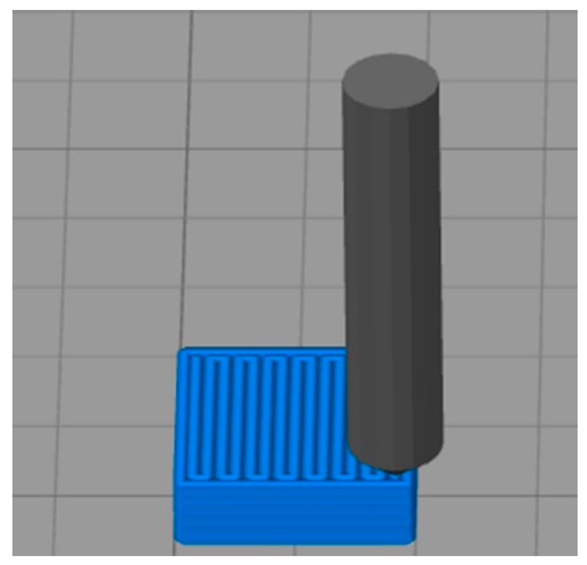
| Parameters | Technical Specifications |
|---|---|
| Extruder diameter | 0.6 mm |
| Printing layer thickness | 0.1 mm or 0.3 mm |
| Print speed | 10 mm/s |
| Printing table temperature | 160 °C |
| Chamber temperature | 100 °C |
| Extruder temperature | 380 °C |
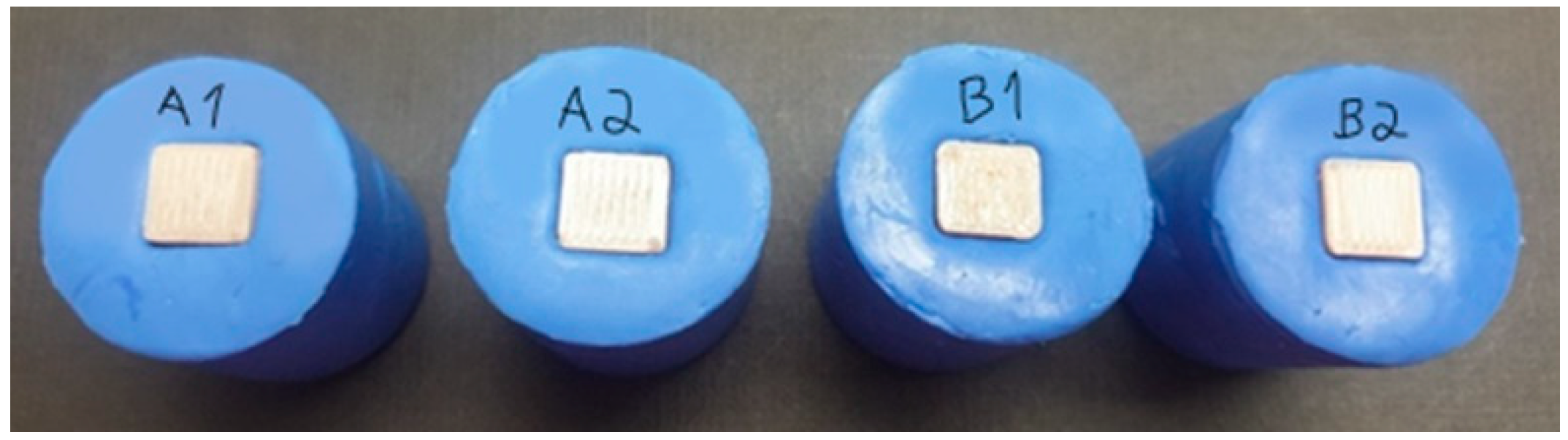
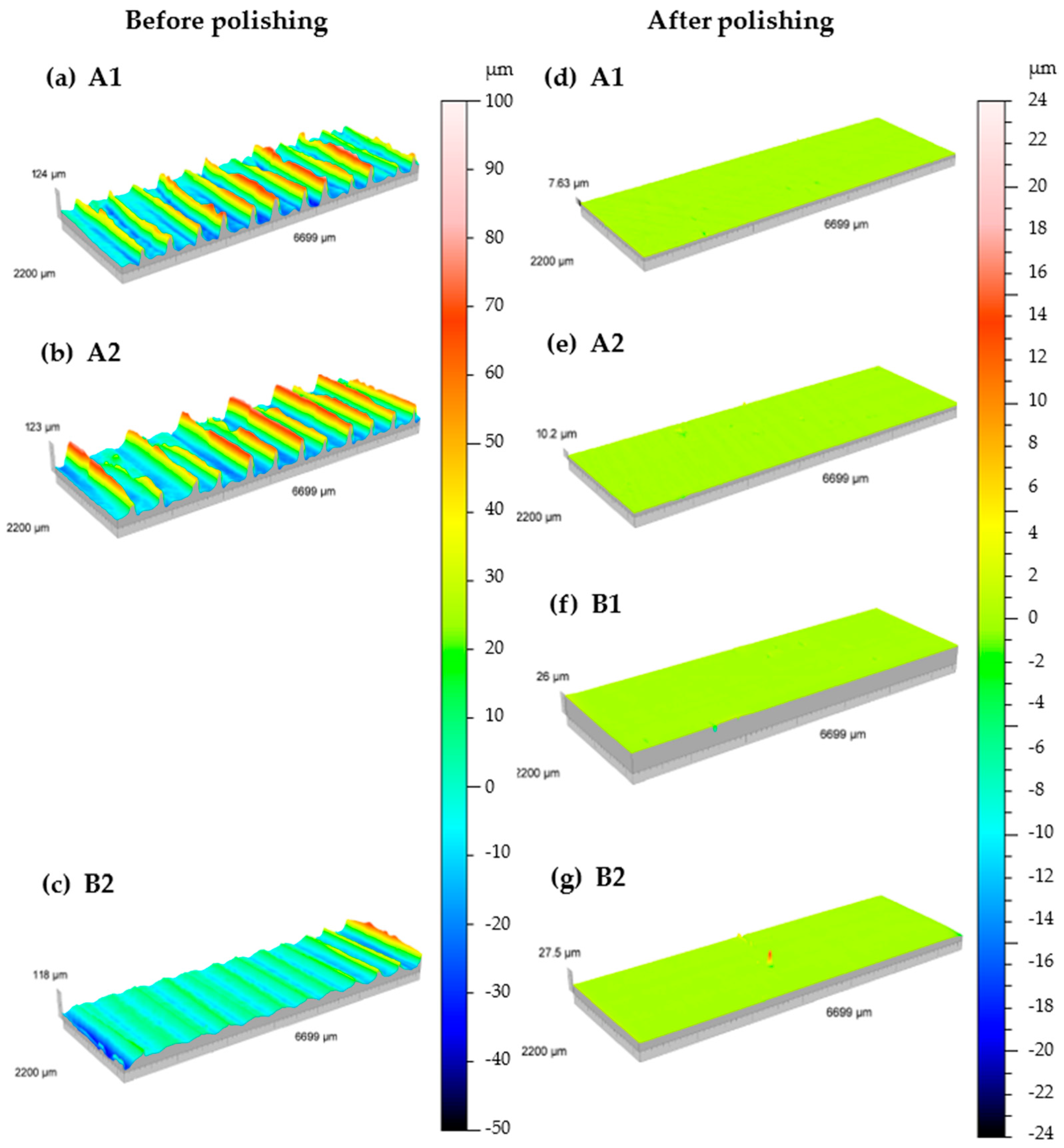
| Specimens | Roughness Parameters | Before Polishing (μm) | After Polishing (μm) |
|---|---|---|---|
| A1 | Sa | 17.3 | 0.19 |
| Ra | 0.91 | 0.12 | |
| St | 124 | 7.64 | |
| A2 | Sa | 18 | 0.15 |
| Ra | 1.05 | 0.09 | |
| St | 123 | 10.2 | |
| B1 | Sa | 0.09 | |
| Ra | 0.05 | ||
| St | 26 | ||
| B2 | Sa | 6.51 | 0.1 |
| Ra | 0.33 | 0.05 | |
| St | 118 | 27.5 |
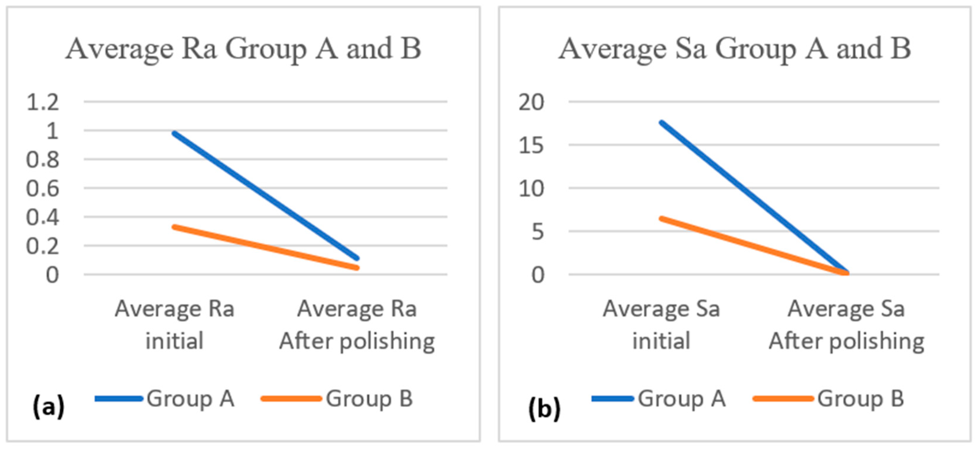
| Group | Group Average Ra (μm) | Group Average Sa (μm) | ||
|---|---|---|---|---|
| Before polishing | After polishing | Before polishing | After polishing | |
| A (A1 and A2) | 0.98 | 0.11 | 17.65 | 0.17 |
| B (B1 and B2) | 0.33 | 0.05 | 6.51 | 0.09 |
| Specimens | P1 (Unfinished Specimen) | P2 Polished with SiC Sandpaper) | P3 (Conventional Finish) | |
|---|---|---|---|---|
| Roughness Parameters | Sa | 0.74 | 0.4 | 0.49 |
| Ra | 0.26 | 0.11 | 0.11 | |
| St | 9.75 | 7.68 | 6.62 | |
| Specimens | Arithmetic Mean Roughness (Ra) before Polishing ± SD (μm) | Arithmetic Mean Roughness (Ra) after Polishing ± SD (μm) |
|---|---|---|
| PEEK—Group A | 0.98 ± 0.07 | 0.11 ± 0.02 |
| PEEK—Group B | 0.33 ± * | 0.04 ± 0 |
| PMMA | 0.26 ± * | 0.11 ± * |
Disclaimer/Publisher’s Note: The statements, opinions and data contained in all publications are solely those of the individual author(s) and contributor(s) and not of MDPI and/or the editor(s). MDPI and/or the editor(s) disclaim responsibility for any injury to people or property resulting from any ideas, methods, instructions or products referred to in the content. |
© 2024 by the authors. Licensee MDPI, Basel, Switzerland. This article is an open access article distributed under the terms and conditions of the Creative Commons Attribution (CC BY) license (https://creativecommons.org/licenses/by/4.0/).
Share and Cite
Soares, T.; Fernandes, C.; Barbosa, C.; Vaz, M.A.P.; Reis, T.; Figueiral, M.H. Surface Roughness of Polyetheretherketone Printed by Fused Deposition Modeling: A Pilot Study Investigating the Impact of Print Layer Thickness and Polishing Method. Appl. Sci. 2024, 14, 3096. https://doi.org/10.3390/app14073096
Soares T, Fernandes C, Barbosa C, Vaz MAP, Reis T, Figueiral MH. Surface Roughness of Polyetheretherketone Printed by Fused Deposition Modeling: A Pilot Study Investigating the Impact of Print Layer Thickness and Polishing Method. Applied Sciences. 2024; 14(7):3096. https://doi.org/10.3390/app14073096
Chicago/Turabian StyleSoares, Tânia, Carlos Fernandes, Cláudia Barbosa, Mário A. P. Vaz, Tiago Reis, and Maria Helena Figueiral. 2024. "Surface Roughness of Polyetheretherketone Printed by Fused Deposition Modeling: A Pilot Study Investigating the Impact of Print Layer Thickness and Polishing Method" Applied Sciences 14, no. 7: 3096. https://doi.org/10.3390/app14073096
APA StyleSoares, T., Fernandes, C., Barbosa, C., Vaz, M. A. P., Reis, T., & Figueiral, M. H. (2024). Surface Roughness of Polyetheretherketone Printed by Fused Deposition Modeling: A Pilot Study Investigating the Impact of Print Layer Thickness and Polishing Method. Applied Sciences, 14(7), 3096. https://doi.org/10.3390/app14073096