Article

Structural Performance of Reinforced Concrete Beams Retrofitted Using Modularized Steel Plates in Precast Concrete with Bolted Connections

Department of Architectural Engineering, Kyung Hee University, Deogyeong-Daero 1732, Yongin 17104, Republic of Korea
*
Author to whom correspondence should be addressed.
Appl. Sci. 2024, 14(8), 3137; https://doi.org/10.3390/app14083137
Submission received: 4 March 2024 / Revised: 3 April 2024 / Accepted: 5 April 2024 / Published: 9 April 2024

Abstract

:
The previous research introduced an innovative retrofitting technique for reinforced concrete beams using modularized steel plates. This technique enhances structural performance, offering a lightweight solution compared to conventional retrofitting methods using steel plates, and accommodates construction errors. However, a challenge arises due to the lack of integrity between unit steel plates. To address this, this study proposes a novel method of connecting each steel plate with bolts. The experimental results show that retrofitted beams achieved a maximum load of 311.9 kN, roughly 1.6 times that of non-retrofitted specimens, with the ductility of retrofitted beams being 3.3 times that of the non-retrofitted beams. Additionally, there was a 25% increase in load capacity for beams retrofitted with interconnected steel plates compared to those without connections between unit steel plates.

1. Introduction

Reinforced concrete (RC) structures experience degradation throughout their lifespan. Notably, structures without seismic design require seismic retrofitting. To address these issues, various retrofit techniques have been explored and implemented. The retrofitting of RC structures primarily targets columns and beams, with each possessing unique retrofit requirements dictated by their functional roles and characteristics. Columns play a crucial role in dissipating energy during seismic events. To enhance this capability, strategies such as integration of dampers, enlargement of cross-sections, and bracing have been employed to resist seismic load [1,2,3]. The RC beam primarily serves as a material resistant to bending. Therefore, the retrofitting strategy for beams is focused on enhancing their flexural capacity. In this context, fiber-reinforced polymers (FRP) and steel plates have been widely adopted [4,5,6,7,8,9,10,11,12,13,14,15,16,17,18,19,20,21,22,23,24]. Additionally, one widely used method for retrofitting beams is utilizing fiber-reinforced materials such as ultra-high-performance concrete [16,17,18,19,20]. Shang et al. [16] and Ramezani [17] conducted a comprehensive review focusing on recent advancements in evaluating the efficacy of reinforced concrete (RC) structures enhanced with engineered cementitious composite (ECC). ECC exhibits notable properties such as tensile strain hardening behavior and robust interfacial bonding capabilities with substrate concrete, rendering it a viable candidate for retrofitting applications. This review showed that employing ECC for strengthening purposes significantly enhances the structural performance of RC systems. The investigation conducted by Huang et al. [18] examined reinforced concrete beams retrofitted using either ultra-high-performance concrete (UHPC) or carbon fiber-reinforced polymer (CFRP). Their findings revealed that UHPC exhibits superior toughness, displacement capacity, and fracture energy compared to CFRP retrofitting. Consequently, UHPC emerges as a favorable option for strengthening reinforced concrete structures, offering both technical advantages and economic benefits. Additionally, Ramezani [19] and Barham [20] delved into a retrofitting approach utilizing carbon nanotubes (CNTs). Their studies demonstrated that CNTs effectively fills voids within the concrete matrix, resulting in a notable enhancement in compressive strength.
Teguh M. proposed a cost-effective method for repairing damage in the existing frame structure with enhanced strength and ductility [21]. However, retrofitting RC beams presents challenges, such as limited workspace availability and the use of heavy retrofit materials. Although FRP can mitigate some of these issues by employing strips, its inherent material properties may cause brittle failures [10]. Both steel plate and FRP methods are prone to debonding issues with RC components [22,23]. Cracks in RC beams can be observed before the full potential of steel plates or FRP is realized, leading to debonding and compromised structural integrity.
Recent studies [24,25] introduced an innovative retrofitting approach for RC beams using modularized steel plates, bypassing the constraints of traditional RC beams retrofitted with FRP and steel plates. This novel method presents benefits including weight, construction ease, and adaptability to various beam sizes. Importantly, it effectively overcomes debonding issues and enhances the structural performance of the existing RC beam by approximately 1.8 times [25]. However, in this new method, the modularized steel plates were not bonded to each other, and integration with the RC beam relied solely on chemical anchors. Experimental results from previous research [24,25] confirmed that when the RC beam experiences bending moments, gaps occur between the modularized steel plates. Therefore, the primary objective of the present study is to develop an innovative connection between modularized steel plates, addressing this shortcoming in the existing retrofitting approach. This study aims to introduce improvements to the modularized steel plate retrofitting method, with the goal of providing a more reliable technique for retrofitting RC beams.

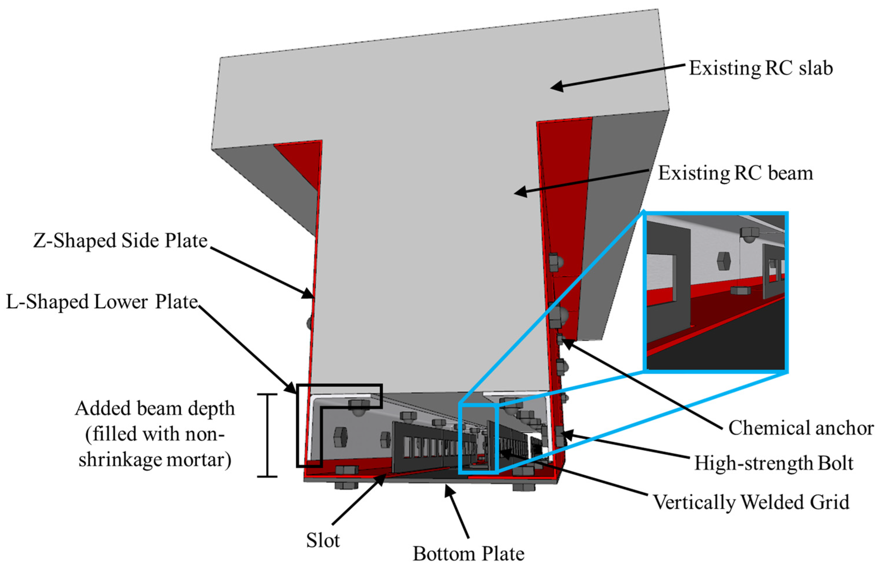
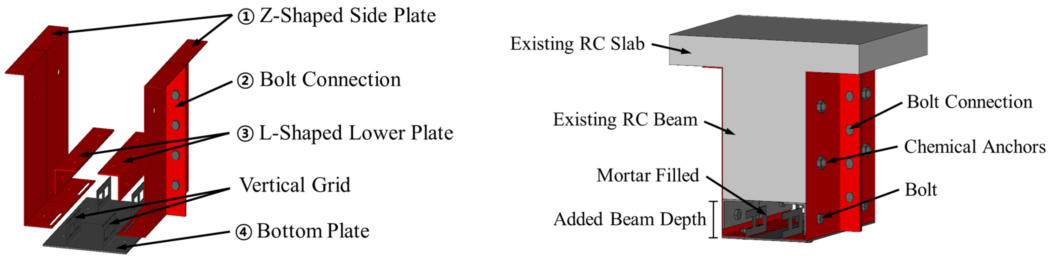
2. Concept of the Modularized Steel Plate with Bolt Connections

A previous study [24] introduced a novel retrofitting technique for RC beams utilizing modularized steel plates. This method entails encasing the RC beam with a steel plate, which establishes a void between the beam and steel plate that is subsequently filled with non-shrinkage mortar to address concerns regarding mortar shrinkage and to ensure workability during construction. This approach amalgamates the concrete jacketing technique with a retrofitting method employing steel plates or FRP. The jacketing procedure augments the rigidity and strength of the existing RC beam, whereas the steel plate bolsters its ductility. Figure 1 is a schematic representation of the components associated with modularized steel plates.
The proposed technique is conceptualized in a singular-unit format to simplify construction. A single unit comprises a Z-shaped side plate, an L-shaped lower plate, and a bottom plate. The Z-shaped side plate, affixed to the RC beam side, enhances its ductility and strength. Each lower plate is L-shaped, comprising two pieces that form one component. Therefore, since lower plates are attached at both ends of the beam width, if the beam width changes due to construction errors, they can be attached according to the beam width, accommodating for construction errors. These plates are interconnected using bolts, with their dimensions determined by the intended enlargement section, specifically the depth of the newly added beam. The bottom plate enveloping the base of the added beam ensures ductility, especially since it resides in the tension zone. This plate is equipped with a vertically welded grid, serving as the tensile reinforcing bar and improving bond capacity in the added beam, seamlessly integrating into the slot at the base of the Z-shaped side plate. The statement that vertically welded grids can serve the function of tensile reinforcing bars within the added beam was supported by the findings derived from the author’s previous research [24]. The bond between the steel plate and the existing RC beam is realized using chemical anchors.
For ease of handling, the modularized steel plate retrofitting approach is segmented into units, each reinforcing the RC beam. A previous study [24] observed stress concentration at the interconnections of units when subjected to flexural load. To rectify this, the current research introduces an enhanced detail to fortify the inter-unit joints, as illustrated in Figure 2. This novel detail is a joint steel plate connected to the Z-shaped side plate, with Z-shaped plates of adjacent units bolted together. Contrary to the initial joint design, which solely anchored the Z-shaped side plate to the RC beam without inter-module connections, the revised method interlinks the Z-shaped side plates, ensuring cohesive behavior across modules. This enhancement retains the original modularized steel plate components, presenting the benefits of straightforward design and fabrication.
The construction procedure for the modularized steel plate is sequentially delineated below. Notably, the construction solely relies on chemical anchors or high-strength bolts, obviating the need for specialized labor. This not only results in cost savings but also expedites the construction process due to its simplicity.
(1)
The surface preparation of the concrete, for example, removing surface contaminants, is conducted, and later, the L-shaped lower plate, with its protrusion, is affixed to the RC beam underside utilizing chemical anchors;
(2)
The L-shaped lower plate and the Z-shaped side plate are interconnected using high-strength bolts. The bottom plate is slotted into the designated groove at the Z-shaped side plate base. After aligning the bottom plate with the Z-shaped side plate, they are secured using high-strength bolts;
(3)
The Z-shaped side plate is anchored to the concrete beam side via chemical anchors;
(4)
The void between the L-shaped lower plate and the bottom plate is filled with non-shrinkage mortar, facilitating the formation of the added beam;
(5)
For instances incorporating joint details between modularized steel plates, high-strength bolts are employed for the connection.

3. Experimental Program

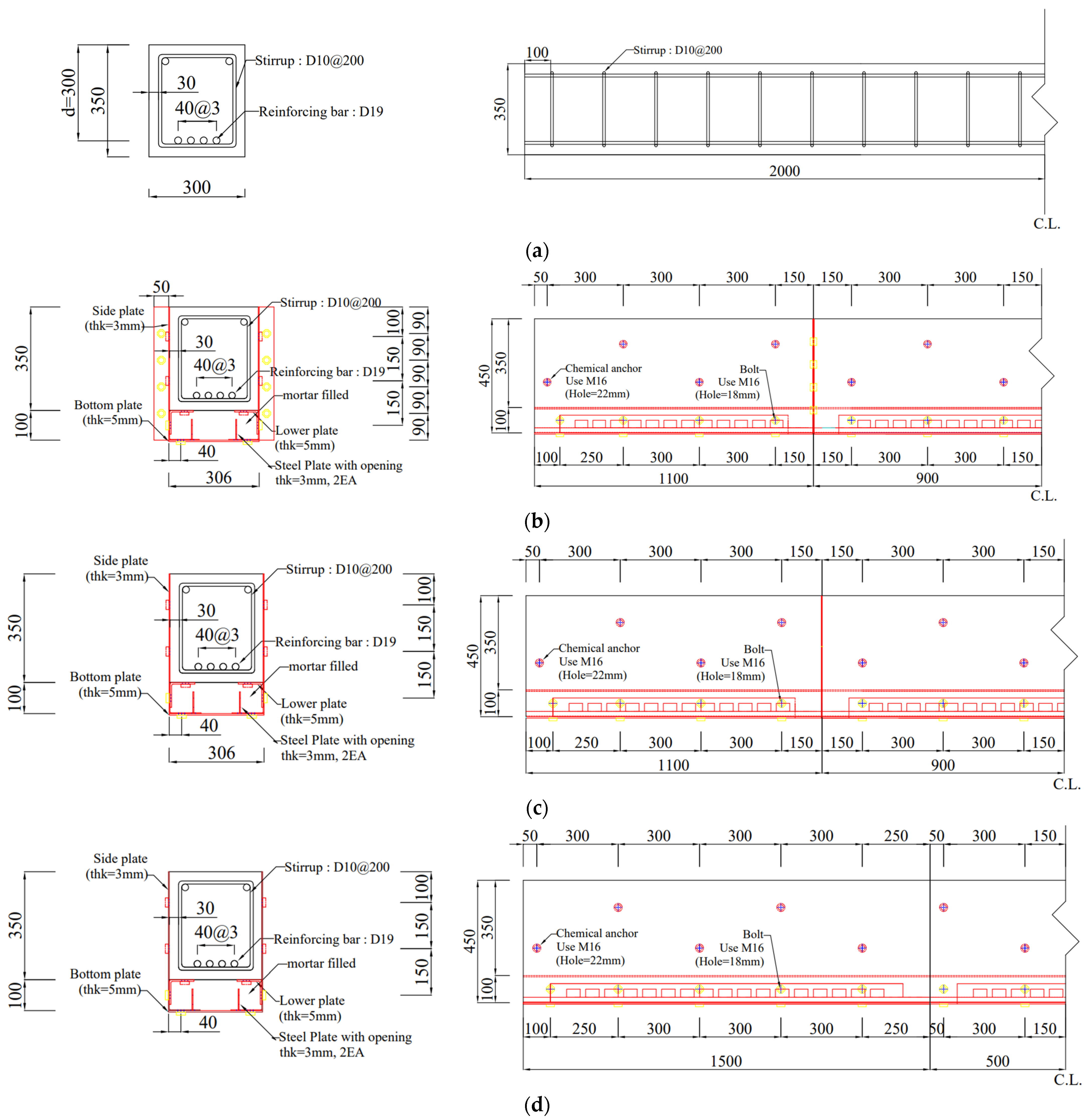
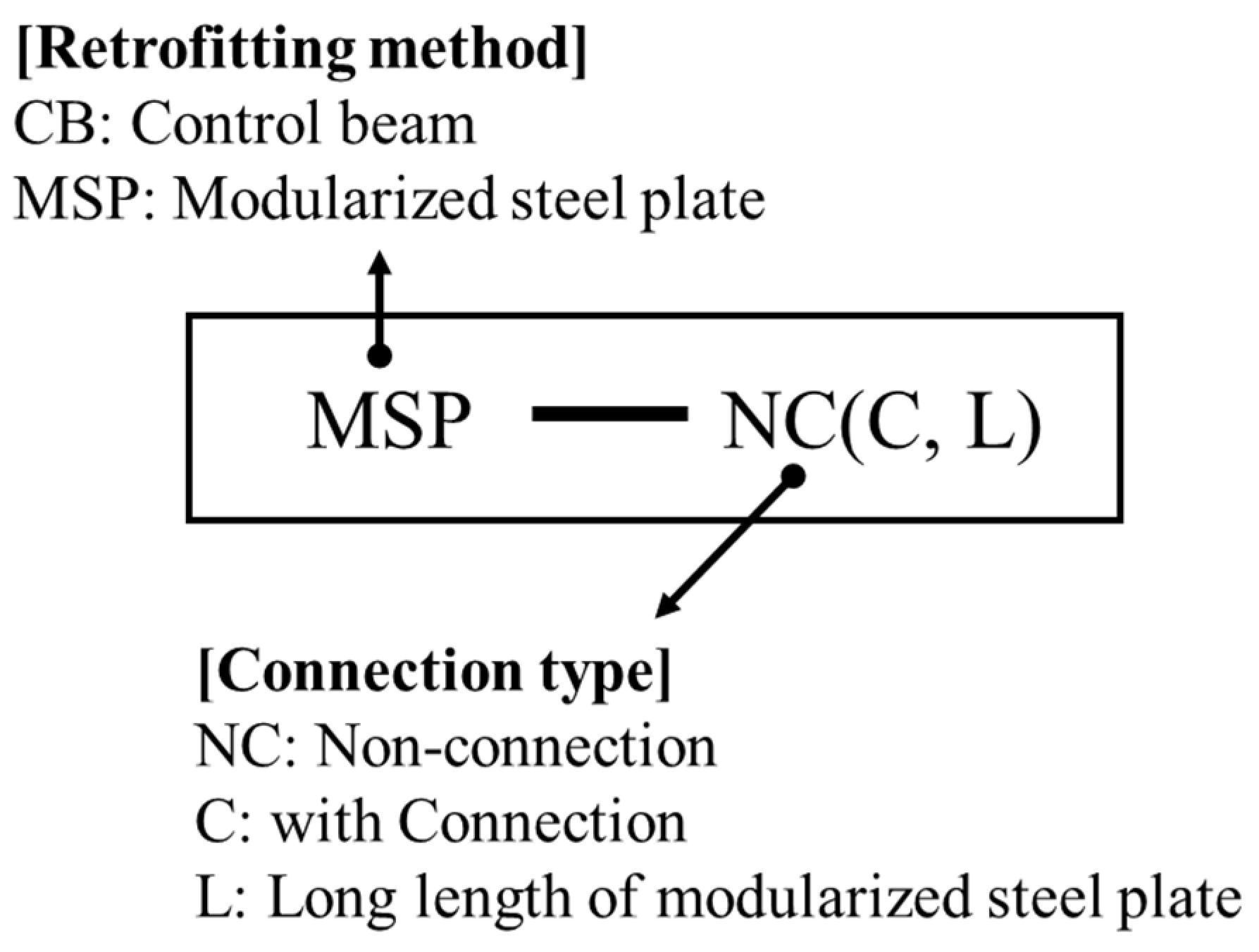
3.1. Specimen Details
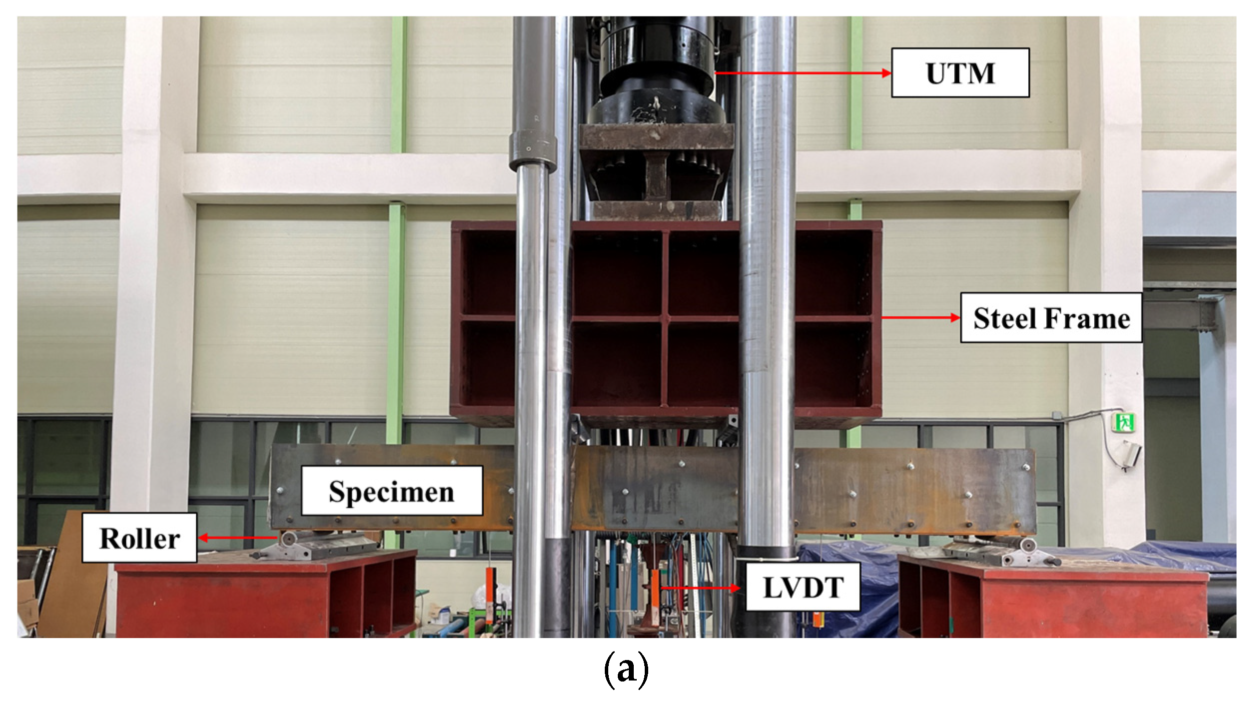
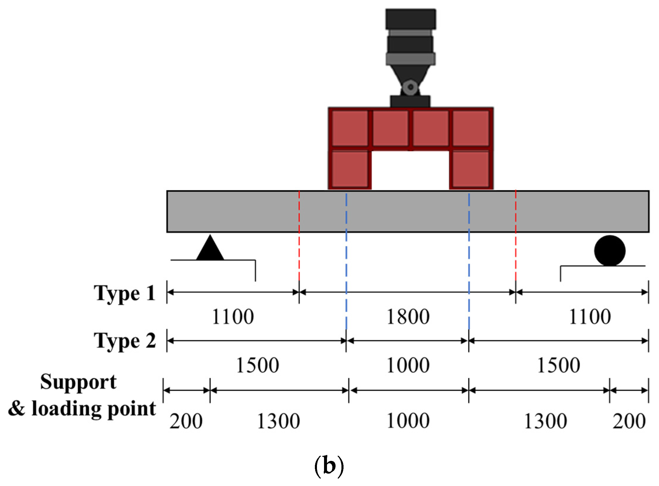
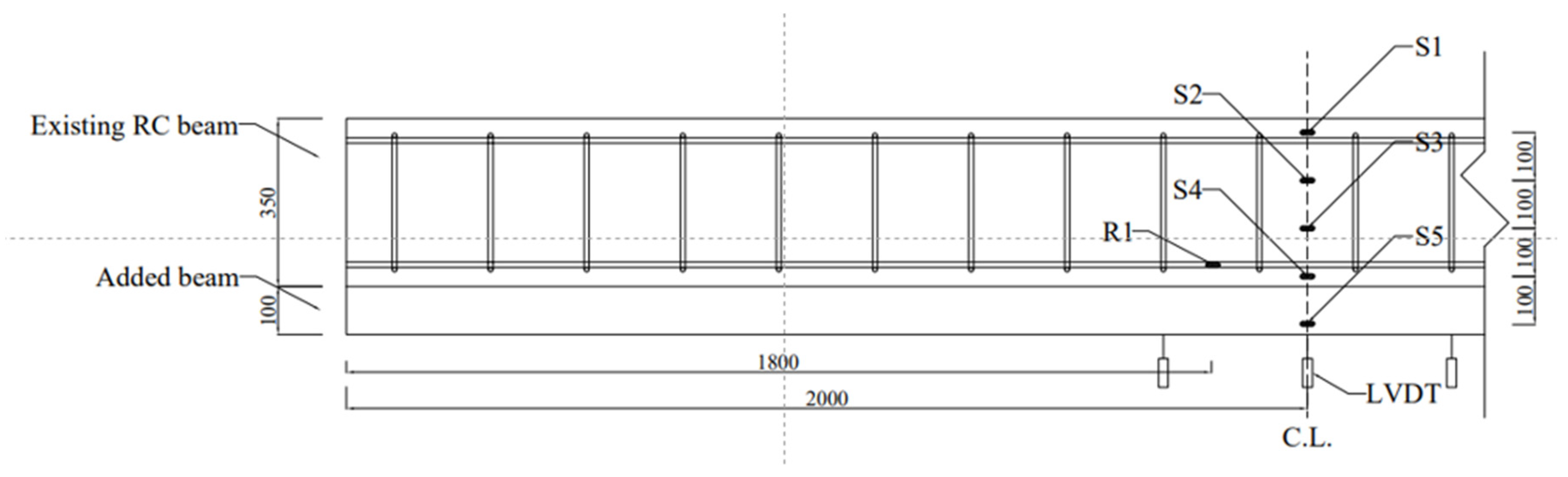
This research aims to assess the structural behavior of RC beams contingent upon the module dimensions and the existence or nonexistence of interconnections within the modularized steel plate. To achieve this, one non-retrofitted specimen and three specimens retrofitted using modularized steel plates were fabricated. The specifics of these specimens are detailed in Table 1 and illustrated in Figure 3. While the modularized steel plate is intended to encase both the slab and beam in real onsite applications, this investigation solely concentrated on the RC beam behavior. Hence, the steel plate was designed to wrap solely around the beam, as depicted in Figure 3.
All specimens comprised RC beams measuring 300 mm in width, 350 mm in height, and 4000 mm in total length. The depth of the beam retrofitted with steel plates was set at 100 mm to prevent the retrofitted RC beams from becoming a deep beam. The thickness of the Z-shaped side plate and vertical grid was 3 mm. In contrast, the L-shaped lower plate and bottom plate, which directly impact ductility, were designed with thicknesses of 5 mm. Chemical anchors, utilized to secure the existing structure and the steel plate, were spaced at 300 mm intervals and had a diameter of 16 mm. The joint width between steel plates was 50 mm with a bolt spacing of 90 mm. High-strength bolts with diameters of 16 mm were employed for the connections. The size of one unit was categorized into two types. Type 1 comprised steel plates of lengths of 1.1 m, 1.8 m, and 1.1 m, whereas type 2 consisted of lengths of 1.5 m, 1 m, and 1.5 m. This distinction was important, as the overall structural behavior of the steel plate varies based on the joint’s position relative to the load application point. Notably, type 1 lacks a joint within the load application area, while type 2 possesses a joint at this location. Figure 4 is notation of specimens.
To validate the structural behavior of RC beams retrofitted with modularized steel plates, the tensile reinforcing bar and stirrups were designed to ensure that bending failure preceded shear failure. The incorporated tensile reinforcing bar was a deformed bar with a diameter of 19 mm, while the stirrups were constructed using a deformed bar with a diameter of 10 mm. The concrete used in specimen fabrication had a compressive strength of 23 MPa, the tensile reinforcing bar had a yield strength of 400 MPa, and the steel plate had yield strength of 275 MPa.

3.2. Test Setup

A test was executed on simply supported specimens using a hydraulic universal testing machine (UTM) with a 5000 kN capacity, progressing at a rate of 2 mm/min, as illustrated in Figure 5. The load application point for all specimens was uniformly set at a distance of 1000 mm. The distinct load application patterns for each type, determined by the modularized steel plate length, are presented in Figure 5b. The testing procedure was concluded when the load decreased to less than 80% of its peak after achieving the maximum load. A linear variable differential transformer (LVDT) was positioned at the specimen midpoint to record deflection. Strain gauges, as depicted in Figure 6, were affixed to capture the deformation of the tensile reinforcing bar and steel plates. The gauge affixed to the tensile reinforcing bar is designated as R1, and those on the steel plate are labeled S1 through S5.

4. Experimental Results and Analysis

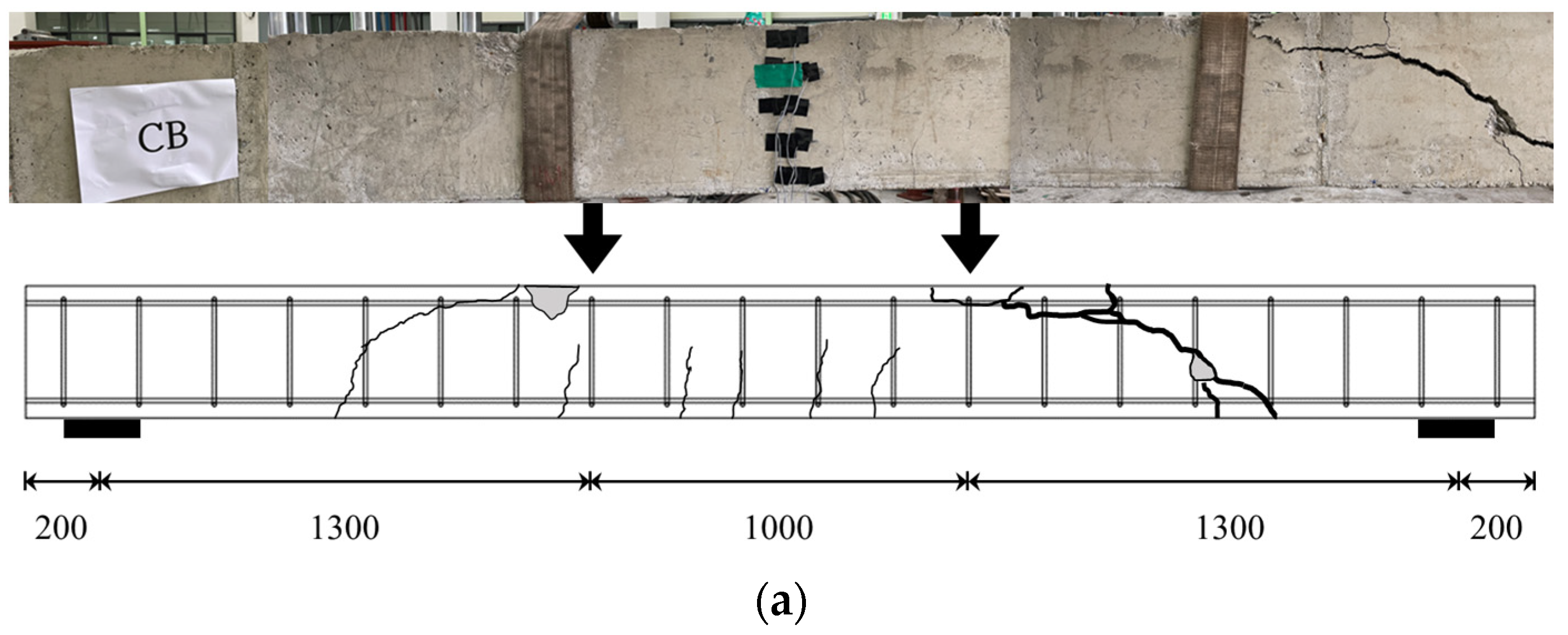
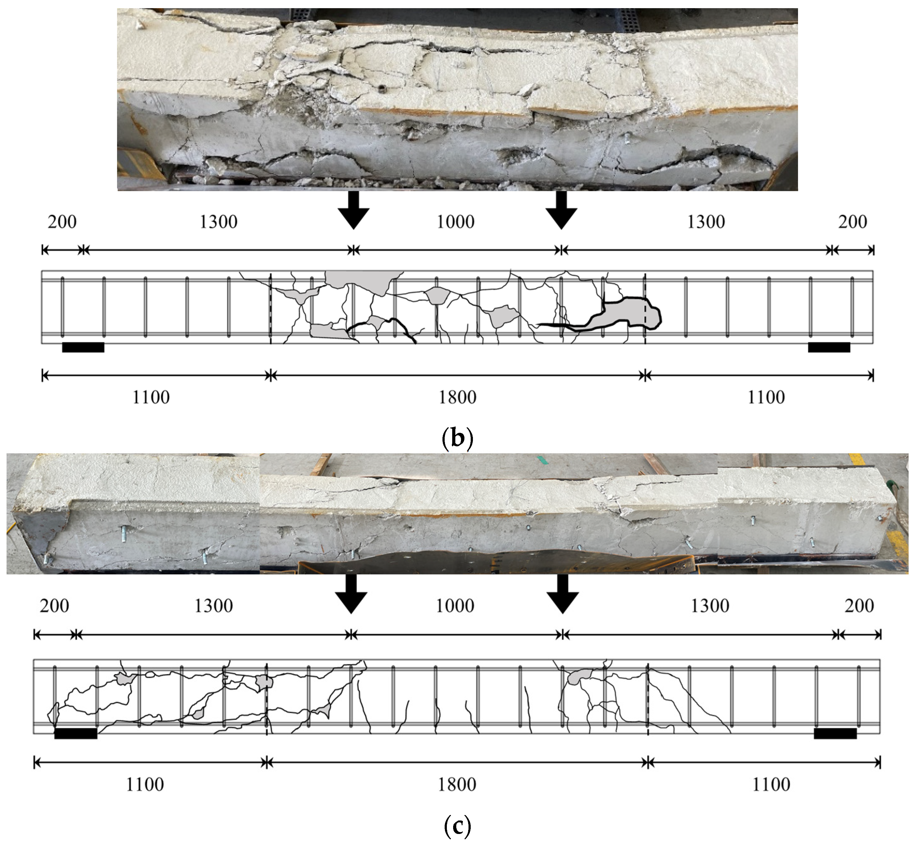
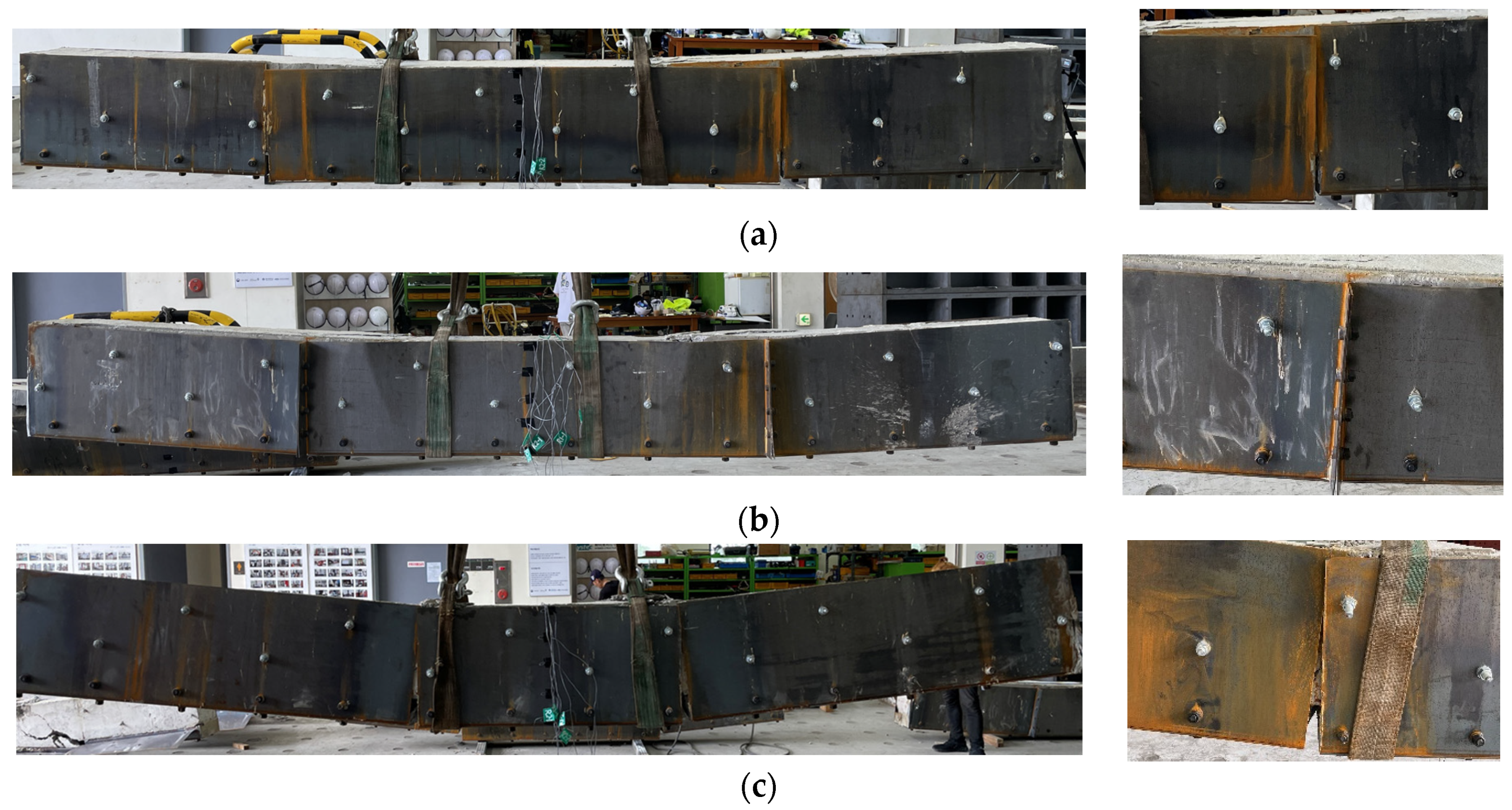
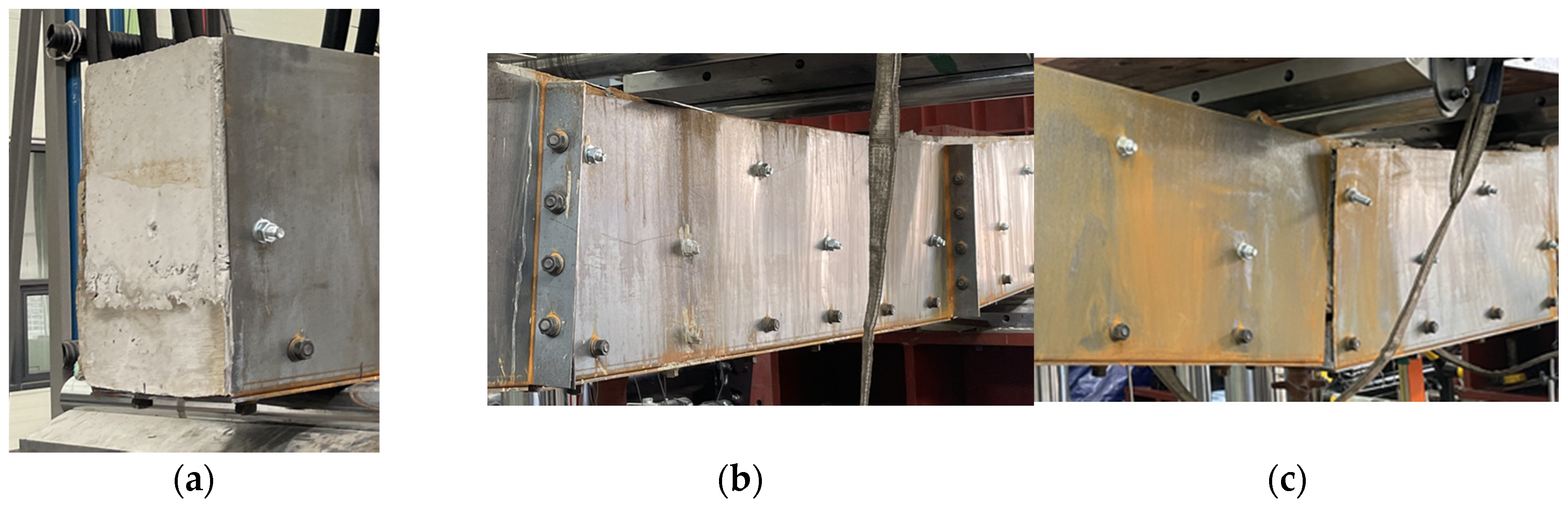
4.1. Crack Propagation and Failure Modes

Figure 7 presents the experimental results for all specimens, encompassing crack propagation and the observed failure mode. Subsequent to the testing phase, the crack propagation in specimens retrofitted with modularized steel plates was inspected by detaching the steel plates. For the MSP-L specimen, due to safety considerations, steel plate removal was not feasible. Hence, its crack propagation remains undocumented. The non-retrofitted specimen, labeled CB, manifested initial flexural cracks centrally, which subsequently evolved into shear cracks extending from the supports to the load application points. The propagation of these shear cracks culminated in concrete spalling in the compression zone, resulting in brittle failure.
In comparison, specimens retrofitted using modularized steel plates demonstrated shear cracks similar to those in CB. However, these specimens experienced more frequent flexural cracks within their tension zones, narrower shear crack widths, and an abundance of minute cracks. The MSP-NC specimen, which lacked bolted connections between its steel plates, displayed significant concrete spalling within its tension zone compared to its bolt-connected counterpart, MSP-C. The failure mode of MSP-C was predominantly concrete crushing at the point of load application. In contrast, MSP-NC exhibited intensified cracking at its interface with the steel plate, indicating a lack of cohesive behavior. The absence of connections between the steel plates in MSP-NC resulted in a deviation in its flexural behavior compared to the RC beam. This led to the steel plates in MSP-NC bearing less tensile force than those in MSP-C. Figure 8 supports this, showing that the Z-shaped side plates in MSP-C underwent more pronounced deformation than those in MSP-NC, with clear signs of debonding evident in MSP-NC. Upon analyzing the behavior of modularized steel plates with different unit dimensions, as illustrated in Figure 8b,c, both MSP-C and MSP-L lacked interconnections. As shown in Figure 5b, while MSP-C was subjected to load within a single module, MSP-L experienced loading at the terminal points of the module. The concentrated loading at these terminal points exposed MSP-L to forces that promoted debonding. The lack of connections between modules led to almost complete separation of MSP-L after testing. This highlights the importance of module dimensions based on the load borne by the RC beam and the mechanism of load transfer.
The effectiveness of retrofitting methods that attach reinforcements to pre-existing structures is largely influenced by the bonding strength between the core material and the added reinforcement. Figure 9 provides a detailed view of the bond status post testing between the RC beam and steel plate. Within an individual module, the steel plate maintained a strong bond with the existing RC beam on both its sides and bottom. Additionally, there were no signs of bolt loosening, joint shearing, or any form of buckling in the steel plates.

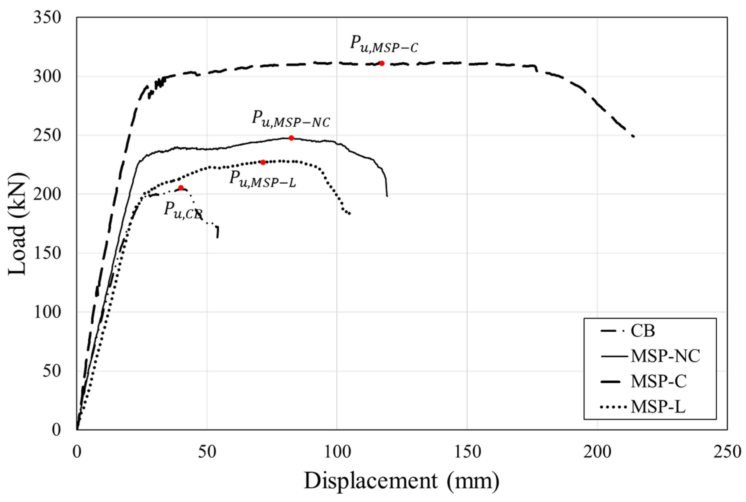
4.2. Load–Displacement Relationships and Initial Stiffness

Table 2 presents the experimental results, and Figure 10 illustrates the load–displacement curves for each specimen. Specimens retrofitted with modularized steel plates showed an average maximum load of 262.6 kN, about 1.3 times the maximum load of the non-retrofitted concrete beam, CB. The initial stiffness of CB was 8.87 kN/mm, while the retrofitted specimens had an average stiffness of 10.3 kN/mm. These data suggest that the modularized steel plate significantly enhances the stiffness of the pre-existing RC beam, likely due to the added section between the steel plate and existing beam.
In terms of steel plate connectivity, MSP-NC, without interconnected steel plates, reached a maximum load of 247.65 kN. On the other hand, MSP-C, with bolted steel plate connections, achieved a maximum load of 311.95 kN. This indicates that operation of the modularized steel plate as a cohesive unit improves its load capacity by about 25% compared to when it operates in isolation. The initial stiffness also exhibited an increase of approximately 21%. The performance based on module size was analyzed using MSP-NC and MSP-L. MSP-L, which was loaded at the steel plate connection, had a maximum load of 228.24 kN, about 85% of the maximum load of MSP-NC where the load was applied within a single module. This suggests that the performance of the modularized steel plate is influenced by the size of the module and the position of load application. Furthermore, even without specific connections between steel plates, optimizing module dimensions based on the load distribution of the RC beam can lead to more highly integrated behavior.

4.3. Ductility Capacity

Ductility is the ability of a material to undergo substantial deformation beyond its elastic limit without experiencing failure. This study investigated the flexural behavior of RC beams retrofitted with modular steel plates, aiming to assess their deformation capabilities in terms of ductility. The displacement ductility ratio ( μ ) is determined by dividing the displacement at maximum strength ( δ u ) by the displacement at the yield point ( δ y ), as shown in Equation (1). The yield point for this study is the intersection of the load–displacement curve and a line parallel to the initial stiffness, as outlined in a previous study [24].
μ = δ u δ y
The displacement ductility ratios for each test specimen, calculated using Equation (1), are presented in Table 3. The results indicate that incorporation of modular steel plates can enhance the ductility of RC beams by approximately a factor of two. This improvement is attributed to the steel plate strategically positioned on the tension zone of the RC beam, which mitigates crack propagation under bending loads. The specimens, labeled MSP-NC and MSP-L, which lack interconnected steel plates, exhibited comparable ductility irrespective of their modular dimensions. These specimens achieved a ductility index close to 2.9, nearly twice that of the control RC beam (CB). Conversely, the MSP-NC specimen with bolted steel plate connections achieved a ductility index of 4.6, almost three times greater than that of the CB. This value is approximately 1.6 times greater than that of specimens without interconnected steel plates, underscoring the notion that the enhancement attributed to the modularized steel plate is critically influenced by the integration efficacy of the plates.

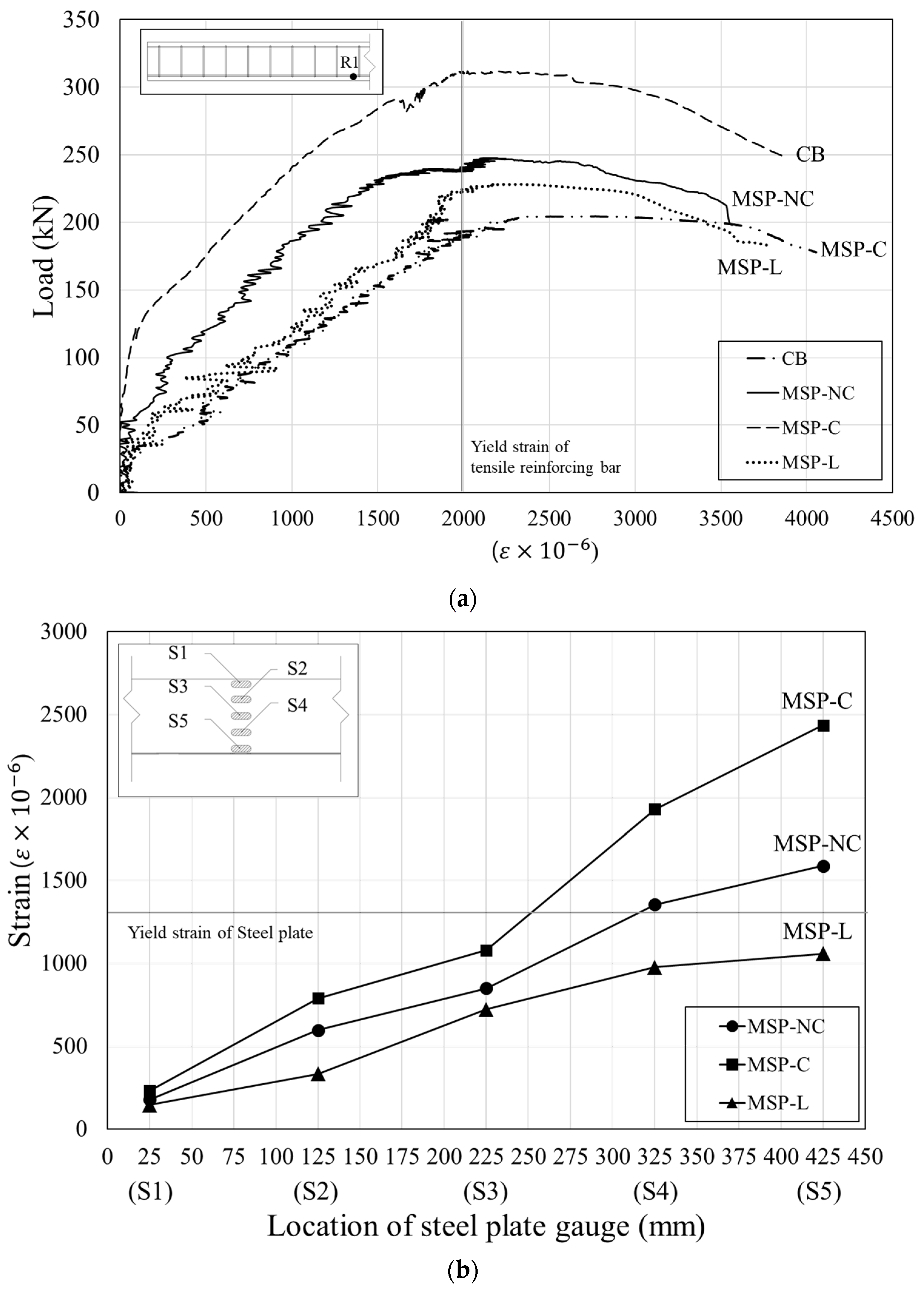
4.4. Load-Strain Behavior

Figure 11a delineates the strain distribution by the tensile reinforcing bar within the RC beam, and Figure 11b illustrates the strain exhibited by the Z-shaped side plate in specimens retrofitted with modularized steel plates at maximum load. The analysis of the load–strain relationship for the tensile reinforcing bar illustrated in Figure 11a reveals that all specimens reached a yield strain threshold of 0.002 just prior to peak load, indicating the initiation of yielding. Following this, the specimens transitioned into the plastic region, culminating in failure. In the comparative assessment of strain within the tensile reinforcing bar at identical loads, the non-retrofitted concrete beam manifested the most pronounced strain. In beams retrofitted with modularized steel plates, the strain within the tensile reinforcing bar was decreased slightly. This can be attributed to the resistance to tensile forces by not solely the tensile reinforcing bar of the existing RC beam but also the vertical grid and bottom plate of the added section. This observation accentuates the efficacy of the modularized steel plate in counteracting tensile forces.
Figure 11b provides an in-depth depiction of the deformation behavior exhibited by the Z-shaped side plate, which is laterally attached to the existing beam. The S1 gauge located within the beam’s compression zone recorded minimal deformation across all specimens, a result of the steel plate’s inability to resist tensile forces in that region. A pattern was observed wherein the strain in the steel plate progressively increased as it neared the tension zone of the beam. The added beam is positioned 350 mm from the compressive surface of the existing RC beam, and the S4 and S5 gauges are situated within this region. Importantly, in the MSP-C specimen, which is distinguished by its interconnected steel plates promoting integrated behavior, the strains registered at the S4 and S5 locations were notably higher compared to that at S3, reaching a yield strain of 0.001375. This suggests that interconnected steel plates allow synergistic function between the pre-existing RC beam and the newly incorporated section. These results are evidence of the substantial tensile resistance provided by a modularized steel plate when effectively bonded to the beam.

5. Conclusions

This paper builds upon previous research that proposed a retrofitting method for reinforced concrete beams using modularized steel plates. In this study, a bolted connection between steel plates was introduced to address the debonding issue observed in previous research. Moreover, the structural performance of the modularized steel plate was analyzed based on the size of an individual module unit. The main conclusions drawn from this study are as follows.
(1)
The modularized steel plate retrofitting technique was effective in influencing crack propagation in retrofitted RC beams. Specimens retrofitted with this method displayed more flexural cracks in tension zones and exhibited narrower shear crack widths compared to non-retrofitted beams. A key observation was deviation of the flexural behavior due to insufficient connections between the steel plates. This highlighted the significance of robust interconnections to ensure cohesive behavior and to prevent debonding. Furthermore, the interplay between module dimensions and their corresponding loading points became apparent. Concentrated loading at the end of a module increased susceptibility to forces that could lead to debonding. This emphasizes the necessity of aligning module dimensions with anticipated loads and the mechanism of load transfer;
(2)
Retrofitting using the modularized steel plate method significantly enhances the maximum load and stiffness of existing RC beams. Specimens retrofitted with these plates demonstrated maximum load 1.6 times that of non-retrofitted beams. Additionally, interconnected steel plates increased the load capacity by about 25% compared to isolated plates. Both the load application point and module size were crucial in determining modularized steel plate performance;
(3)
The use of modularized steel plates for retrofitting RC beams resulted in a marked increase in ductility, with certain specimens showing almost double the ductility. Specimens with interconnected plates had a ductility index approximately 1.6 times that of those without. Tensile forces were shared between the steel plate and the original RC beam, indicating that the modularized steel plate effectively handles tensile forces. Additionally, the strain levels within these plates increased as they neared the beam’s tension zone, emphasizing the importance of effective bonding;
(4)
The evident differences of load, stiffness, and ductility between specimens with interconnected steel plates and those without highlight the necessity for shear and flexural strength formulas tailored to the connection method. While this research focused on a limited set of specimens to study the effects of steel plate interconnections, future research should include a broader specimen range for a more comprehensive assessment of flexural and shear performance.

Author Contributions

Conceptualization, K.M.R. and Y.H.L.; methodology, K.M.R. and M.S.K.; validation, Y.H.L.; formal analysis, K.M.R. and M.S.K.; investigation, K.M.R. and Y.H.L.; writing—original draft preparation, K.M.R.; writing—review and editing, Y.H.L. All authors have read and agreed to the published version of the manuscript.

Funding

This work was supported by a National Research Foundation of Korea (NRF) grant funded by the Korean government (MSIT) (No. 2019R1A2C1090033 and No. RS-2023-00218832).

Institutional Review Board Statement

Not applicable.

Informed Consent Statement

Not applicable.

Data Availability Statement

The original contributions presented in the study are included in the article, further inquiries can be directed to the corresponding author.

Conflicts of Interest

The authors declare no conflicts of interest.

References

  1. Kim, J.; Shin, H. Seismic loss assessment of a structure retrofitted with slit-friction hybrid dampers. Eng. Struct. 2017, 130, 336–350. [Google Scholar] [CrossRef]
  2. Basha, A.; Fayed, S.; Elsamak, G. Flexural behavior of cracked RC beams retrofitted with strain hardening cementitious composites. KSCE J. Civ. Eng. 2019, 23, 2644–2656. [Google Scholar] [CrossRef]
  3. Hong, S.G.; Lim, W.Y. Strengthening of shear-dominant reinforced concrete beams with ultra-high-performance concrete jacketing. Constr. Build. Mater. 2023, 365, 130043. [Google Scholar] [CrossRef]
  4. Sener, K.C.; Varma, A.H.; Seo, J. Experimental and numerical investigation of the shear behavior of steel-plate composite (SC) beams without shear reinforcement. Eng. Struct. 2016, 127, 495–509. [Google Scholar] [CrossRef]
  5. Zou, G.P.; Xia, P.X.; Shen, X.H.; Wang, P. Investigation on the failure mechanism of steel-concrete steel composite beam. Steel Compos. Struct. 2016, 20, 1183–1191. [Google Scholar] [CrossRef]
  6. Rasheed, H.A.; Abdalla, J.; Hawileh, R.; Al-Tamimi, A.K. Flexural behavior of reinforced concrete beams strengthened with externally bonded Aluminum Alloy plates. Eng. Struct. 2017, 147, 473–485. [Google Scholar] [CrossRef]
  7. Wang, J.J.; Tao, M.X.; Zhou, M.; Nie, X. Force transfer mechanism in RC beams strengthened in shear by means of steel plated concrete. Eng. Struct. 2018, 171, 56–71. [Google Scholar] [CrossRef]
  8. Shen, D.; Jiao, Y.; Li, M.; Liu, C.; Wang, W. Behavior of a 60-year-old reinforced concrete box beam strengthened with Basalt fiber-reinforced polymers using steel plate anchorage. J. Adv. Concr. Technol. 2021, 19, 1100–1119. [Google Scholar] [CrossRef]
  9. Luder, D.; Ariely, S.; Yalin, M. Stress corrosion cracking and brittle failure in a fiber-reinforced plastic (FRP) insulator from a 400 kV transmission line in humid environment. Eng. Fail. Anal. 2019, 95, 206–213. [Google Scholar] [CrossRef]
  10. Baena, M.; Jahani, Y.; Torres, L.; Barris, C.; Perera, R. Flexural performance and end debonding prediction of NSM Carbon FRP-strengthened reinforced concrete beams under different service temperatures. Polymers 2023, 15, 851. [Google Scholar] [CrossRef]
  11. Tiwary, A.K.; Singh, S.; Kumar, R.; Sharma, K.; Chohan, J.S.; Sharma, S.; Singh, J.; Kumar, J.; Deifalla, A.F. Comparative Study on the Behavior of Reinforced Concrete Beam Retrofitted with CFRP Strengthening Techniques. Polymers 2022, 14, 4024. [Google Scholar] [CrossRef]
  12. Eslami, A.; Moghavem, A.; Shayegh, H.R.; Ronagh, H.R. Effect of FRP stitching anchors on ductile performance of shear-deficient RC beams retrofitted using FRP U-wraps. Structures 2020, 23, 407–414. [Google Scholar] [CrossRef]
  13. Yang, X.; Yuan, H.; Li, C.; Wu, L.; Wang, P.; Liu, Y.; Jiang, B.; Wang, Q.; Zhang, X.; Liu, F.; et al. Experimental studies on behavior of failed CRB750 steel bars reinforced concrete beams retrofitted with steel plate. Eng. Struct. 2021, 243, 112539. [Google Scholar] [CrossRef]
  14. Rageh, B.O.; El-Mandouh, M.A.; Elmasry, A.H.; Attia, M.M. Flexural behavior of RC beams strengthened with GFRP laminate and retrofitting with novelty of adhesive material. Buildings 2022, 12, 1444. [Google Scholar] [CrossRef]
  15. Hanifehzadeh, M.; Aryan, H.; Gencturk, B.; Akyniyazov, D. Structural response of steel jacket-uhpc retrofitted reinforced concrete columns under blast loading. Materials 2021, 14, 1521. [Google Scholar] [CrossRef] [PubMed]
  16. Shang, X.Y.; Yu, J.T.; Li, L.Z.; Lu, Z.D. Strengthening of RC structures by using engineered cementitious composites: A review. Sustainability 2019, 11, 3384. [Google Scholar] [CrossRef]
  17. Ramezani, M.; Ozbulut, O.E.; Sherif, M.M. Mechanical characterization of high-strength and ultra-high-performance engineered cementitious composites reinforced with polyvinyl alcohol and polyethylene fibers subjected to monotonic and cyclic loading. Cem. Concr. Compos. 2024, 148, 105472. [Google Scholar] [CrossRef]
  18. Huang, Y.; Lee, M.G.; Kan, Y.C.; Wang, W.C.; Wang, Y.C.; Pan, W.B. Reinforced concrete beams retrofitted with UHPC or CFRP. Case Stud. Constr. Mater. 2022, 17, e01507. [Google Scholar] [CrossRef]
  19. Ramezani, M.; Dehghani, A.; Sherif, M.M. Carbon nanotube reinforced cementitious composites: A comprehensive review. Constr. Build. Mater. 2022, 315, 125100. [Google Scholar] [CrossRef]
  20. Barham, W.S.; Irshidat, M.R.; Awawdeh, A. Repair of Heat-Damaged RC Beams Using Micro-concrete Modified with Carbon Nanotubes. KSCE J. Civ. Eng. 2021, 25, 2534–2543. [Google Scholar] [CrossRef]
  21. Teguh, M. Structural behaviour of precast reinforced concrete frames on a non-engineered building subjected to lateral loads. Int. J. Eng. Technol. Innov. 2016, 6, 152–164. [Google Scholar]
  22. Hu, T.; Zhang, H.; Zhou, J. Prediction of the debonding failure of beams strengthened with FRP through machine learning models. Buildings 2023, 13, 608. [Google Scholar] [CrossRef]
  23. Alam, M.A.; Onik, S.A.; Mustapha, K.N.B. Crack based bond strength model of externally bonded steel plate and CFRP laminate to predict debonding failure of shear strengthened RC beams. J. Build. Eng. 2020, 27, 100943. [Google Scholar] [CrossRef]
  24. Kim, M.S.; Lee, Y.H. Flexural behavior of reinforced concrete beams retrofitted with modularized steel plates. Appl. Sci. 2021, 11, 2348. [Google Scholar] [CrossRef]
  25. Kim, M.S.; Lee, Y.H. Shear behavior of reinforced concrete beam retrofitted with modularized steel plates. Materials 2023, 16, 3419. [Google Scholar] [CrossRef]
Figure 1. Proposed modularized steel plate [24].
Applsci 14 03137 g001
Figure 2. Proposed connection detail.
Applsci 14 03137 g002
Figure 3. Details of the specimens (mm): (a) CB, (b) MSP-NC, (c) MSP-C, and (d) MSP-L.
Applsci 14 03137 g003
Figure 4. Notation of specimens.
Applsci 14 03137 g004
Figure 5. Test setup: (a) photograph and (b) schematic of the test setup.
Applsci 14 03137 g005aApplsci 14 03137 g005b
Figure 6. Locations of the measurement sites (mm).
Applsci 14 03137 g006
Figure 7. Crack patterns for (a) CB, (b) MSP-NC, and (c) MSP-C.
Applsci 14 03137 g007aApplsci 14 03137 g007b
Figure 8. Failure after testing for (a) MSP-NC, (b) MSP-C, and (c) MSP-L.
Applsci 14 03137 g008
Figure 9. Modularized steel plates after testing: (a) side, (b) bottom (MSP-C), and (c) bottom (MSP-L).
Applsci 14 03137 g009
Figure 10. Load–displacement curves.
Applsci 14 03137 g010
Figure 11. (a) Strain of the tensile reinforcing bar and (b) strain of the steel plate.
Applsci 14 03137 g011
Table 1. Details of the specimens.
No.NameRetrofitted MethodBolted Connection DetailLength of Modularized Steel Plate (m)
LeftMiddleRight
1CBNoneNoneNone
2MSP-NCModularized steel plateAbsence1.11.81.1
3MSP-CPresence1.11.81.1
4MSP-LAbsence1.511.5
Table 2. Summary of the test results.
No.Name P u (kN) δ u (mm) K i (kN/mm)
1CB204.4040.398.87
2MSP-NC247.6582.339.74
3MSP-C311.95116.2711.86
4MSP-L228.2478.659.37
P u , maximum load of each specimen; δ u , displacement when maximum load is applied; K i , initial stiffness.
Table 3. Displacement ductility ratio.
No.Name P y (kN) P u (kN) δ y (mm) δ u (mm) μ
1CB199.40204.4026.8740.391.50
2MSP-NC232.75247.6527.7082.332.97
3MSP-C290.45311.9525.38116.274.58
4MSP-L201.83228.2427.4778.652.86
Disclaimer/Publisher’s Note: The statements, opinions and data contained in all publications are solely those of the individual author(s) and contributor(s) and not of MDPI and/or the editor(s). MDPI and/or the editor(s) disclaim responsibility for any injury to people or property resulting from any ideas, methods, instructions or products referred to in the content.

