Abstract
Producing sustainable microfluidic devices on a large scale has become a trend in the biomedical field. However, the transition from laboratory prototyping to large-scale industrial production poses several challenges due to the gap between academia and industry. In this context, prototyping with a mass production approach could be the novel strategy necessary to bridge academic research to the market. Here, the performance of polymer inserts to produce PMMA microfluidic devices using the microinjection moulding process is presented. Inserts were fabricated with an additive manufacturing process: material jetting technology. The importance of the inserts’ orientation on the printing plate in order to produce samples with more uniform thickness and lower roughness has been demonstrated using a flat cavity insert. In addition, preliminary tests were carried out on microstructured inserts with inverted channels of various cross-section shapes (semi-circular or trapezoidal) and widths (200 or 300 µm) in order to investigate the microstructures’ resistance during the moulding cycles. The best geometry was found in the channel with the trapezoidal cross-section with a width equal to 300 µm. Finally, a preliminary microfluidic test was performed to demonstrate the devices’ workability.
1. Introduction
Lab-on-chips (LOCs) and organ-on-chips (OOCs) are revolutionising the healthcare field by making preventive medicine more affordable [1,2]. Due to their ability to miniaturise laboratory processes and physiological functions on microdevices, both microfluidic technologies are at the forefront of biomedical research and diagnostics [3], driving demand for customised medical devices [4]. Certainly, the COVID-19 pandemic, alongside vaccination campaigns and the investigation of biological markers to identify subjects at an elevated risk of hospitalisation [5,6], has accelerated the translation of microfluidic solutions from laboratory to commercial applications through LOC devices for point-of-care [7,8]. In this context, several technologies have been developed and their applications have been extended to various medical fields [9,10], but microfluidics has emerged as a key technology in translating proof of concepts from research laboratories to commercial applications [11]. However, the transition of microfluidic devices from lab prototypes to large-scale production poses several challenges due to the gap between academia and industry [12]. Once a prototype has been developed, the shift to mass production often requires a deep revision of the design, as the materials and technologies used are completely different from prototype fabrication [13,14]. To address this, researchers are investigating rapid and flexible production techniques to meet the growing demand for customised devices crucial for precise disease detection and treatment [15,16,17]. A more focused industrial prototyping approach, based directly on a large-scale process, could be the novel strategy necessary to bridge academic research to the market. Most biomedical microdevices are typically fabricated using PDMS, glass, or silicon through soft lithography or MEMS techniques. However, thermoplastics are preferred for industrial scaling purposes [18] and, recently, polymers such as cyclic olefin copolymer (COC), polymethylmethacrylate (PMMA), and polypropylene (PP) have become widespread materials due to their lower investment costs, specialised knowledge required, transparency, biocompatibility, and high electrical and chemical resistivity [19]. In this context, manufacturing technologies such as cold casting, micromachining, laser ablation, 3D printing, and thermoforming (including injection moulding and hot embossing) are commonly used for the fabrication of LOCS and OOCs, as reported in Table 1 [20,21,22]. When it comes to industrial-scale production, however, microinjection moulding (µIM) seems to be the best performing industrial manufacturing process for high-volume polymeric parts with features below 100 nm and high surface quality replication [23]. Thanks to its high productivity and cost-effectiveness, µIM has also attracted interest in microfluidic manufacturing and it has become a technology highly valued by researchers for the production of affordable medical chips in recent years [24,25].

Table 1.
Comparison of manufacturing processes for microfeatured device manufacturing [24].
Micro injection moulding, like standard injection moulding, is a manufacturing process that typically employs a steel mould as tool for producing polymeric parts. The tool is a pivotal element in the replication and production process chain, containing the negative geometry of the actual part. The combination of the material and manufacturing technologies to produce an insert, as a tool for a mould, can affect the efficiency, life cycle capabilities, and required lead times for tooling production [29]. In recent years, soft tooling has emerged as novel approach, alongside hard tooling, for the rapid fabrication of mould inserts, despite having limited cycle capacity [30]. Although metallic inserts such as stainless steel, nickel, and bulk metallic glass are preferred for moulding devices with micro-structures and precise surface features like LOC [31], these materials do not allow rapid tooling for µIM, a crucial factor for the effective prototyping and scaling of products. In this context, additive manufacturing (AM) offers the opportunity to merge the ease of design changes with an agile manufacturing process [32,33,34]. Soft tool inserts realised using AM have a lower hardness, lower tensile strength, and modulus of elasticity compared to conventional metal tools, making them suitable for industries and applications with low production rates, frequent prototype refinement, or customisation needs, minimising lead times and costs [35,36,37]. In recent years, AM has played a crucial role in biomedical research and diagnostics by enabling the fabrication of biosensors [38,39], tissue [22,26,40] and organ printing [41,42]. Thanks to recent advancements and capabilities in AM, this technology has emerged as a potential alternative for producing µIM inserts for biomedical applications. This approach could reduce the time and cost of prototyping devices and accelerate their transition from laboratories to industry. Several rapid prototyping methods are available, such as fused deposition modeling (FDM), material jetting/multi jet moulding (MJ), stereolithography (SLA) and digital light processing (DLP). Among these, SLA and MJ appear to be the most commonly employed AM techniques for producing resin inserts [43]. These technologies are able to realize parts with high resolution having the possibility to print layer 25 µm height. However, there are limitations in reproducing the microfeatures required for microfluidic chips such as microchannels, pillar arrays, and crossing manifolds, as well as drawbacks related to the material brittleness, which results in decreased tool life during the process, poor accuracy in reproducing structures, and process limitations [44]. Therefore, a careful design of the geometry is essential to optimise the performance of these parts. To enhance the suitability of soft tool inserts for µIM, researchers are focusing their efforts on improving knowledge on the behaviour of resin inserts and reproducing even smaller features. Bagalkot et al. [45] demonstrated, through theoretical and experimental analysis, that features in MJ inserts do not fail primarily due to bending stress from the injection pressure or the localized pressure. Inserts with pin diameters ranging from 3.63 mm to 7.16 mm and aspect ratios from 1.12 to 1.45 were tested, which showed failures from the sixth shot. Krizsma et al. [46] instead investigated the thermal expansion and mechanical deformation of MJ resin inserts with three different wall thicknesses (4 mm, 5 mm, and 6 mm), monitoring cavity pressure and strain with sensors and a strain gauge. A progressive accumulation of residual strain with each IM cycle was observed, and a correlation was established between the strain of the insert and cavity pressure. The 6 mm thick insert failed in the ninth cycle, while the 5 mm thick insert fractured in the thirteenth cycle and the 4 mm thick insert succumbed in the twelfth cycle. Walsh et al. [47] instead performed an experimental campaign using SLA inserts with features of diverse shapes and sizes ranging from 500 µm to 1000 µm to evaluate the thermal conductance and mechanical properties of five photopolymers. The findings suggested that resins with a higher flexural and elongation modulus are more suitable for the µIM process. Also, Gheisari et al. [48] used an SLA system to manufacture three inserts for microcantilevers with thicknesses measuring 30, 120, and 275 µm. All three inserts failed within five injection moulding cycles to produce parts in PP. Dempsey et al. [24] evaluated the insert life produced by a DLP- based inverted SLA process. These inserts exhibited an array of 100-µm wide microfeatures, having different heights and aspect ratios. Following the optimisation of µIM process parameters, the inserts showed a maximum lifetime of 78 moulding cycles before failing. Damage was noted in inserts with higher aspect ratio features, while those with lower aspect ratio features remained unaffected.
The discussed state-of-the-art shows that the main goals in using additive manufacturing in rapid tooling for injection moulding and micro injection moulding aim to determine the number of parts produced, the mechanical strength of the inserts, and the minimum achievable size of the insert microstructures. However, it also highlights the lack of rapid prototyping of microfluidic chips produced by combining AM and µIM techniques.
In this context, the authors tested material jetting technology to produce polymer inserts for micro injection moulding. In this way, microfluidic devices should be prototyped with a mass production approach just at the early stages of the design phase to match the needs of changes in functionalities, producing few test devices with a considerable reduction of time and costs. The MJ technique, compared to other polymer AM processes, ensures higher dimensional accuracy, surface roughness, and high design complexity, thanks to the degradable support material [49]. The importance of insert orientation during 3D printing to produce thin PMMA plates with more uniform thickness and lower roughness has been investigated. Microstructured inserts were realised to test a typical LOC geometry with two different channel sizes (200 and 300 µm) and two different cross-sectional shapes (semi-circular and trapezoidal). The inserts and samples produced were inspected to evaluate process performance, and preliminary microfluidic tests were also performed on some samples to verify the effectiveness of the microchannels.
2. Materials and Methods
2.1. Insert Design
The design activity was divided into two steps: (a) the identification of the best MJ inserts orientation on the printing plate in order to produce PMMA samples with more uniform thickness and lower roughness; and (b) the investigation of insert behaviour for prototyping microfluidic devices with µIM.
Two different resin inserts have been designed and named as follows: a flat insert and a microstuctured insert.
Flat inserts, shown in Figure 1a, have been used in step (a). Two-part orientations to the print direction were analysed: orthogonally (V00) and parallel (V90), according to [50], where the V00 orientation produced resin inserts with higher transparency, while the V90 orientation produced inserts with higher resistance (Figure 1b). Compared to [51], a simplified flat insert geometry has been chosen to reduce the wall side effect during injection moulding.
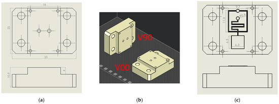
Figure 1.
Design of flat and microfluidic inserts. (a) Flat insert design with main dimensions. (b) Insert V90 and V00 orientation on the print plate. (c) Microstructured insert design with main dimensions.
Based on the results obtained in (a), microstructured inserts (Figure 1c) were realised to investigate the microfeature resistance of the resin insert during moulding cycles (step (b)). Inverted channels with two different cross sections were designed and tested: hemi-cylindrical (S) and trapezoidal (T). S geometry with diameters of 200 µm and 300 µm, T geometry with a height of 200 µm, the smallest base equal to 200 µm and 300 µm, and base angles of 60° were chosen to ensure greater feature resistance and demoulding, in accordance with minimum technology resolution (25 µm) and good results obtained from preliminary experiments. A typical lab-on-chip geometry containing straight and crossed microchannels, reservoirs, and serpentines was reproduced, and its details are reported in Figure 1c.
2.2. Insert and Sample Production
The inserts were produced with the Projet 2500 plus printer (3D System, Rock Hill, NC, USA). The resin selected was commercial VisiJet® M2S-HT250, provided by 3D Systems and fully tested for this kind of application [50], due to its ability to withstand temperatures up to 250 °C [51]. Three inserts were produced for each flat configuration (V00 and V90), and one microstructured insert was produced for each combination of channel shape and width. The inserts were suddenly postprocessed with a heat treatment at 70 °C for 3 h to eliminate the wax that material jetting technology uses as support material, while a second treatment at 70 °C for 8 h was used to stabilise deflections. Figure 2 shows the main fabrication steps.

Figure 2.
Fabrication steps of mould inserts.
The experiments were conducted on the Allround 270A injection moulding machine (Arburg, Lossburg, Germany), equipped with a microinjection module. The resin insert was housed in the main plate of the available steel mould with the interchangeable inserts employed in [52]. The process parameters used are reported in Table 2 and the material injected is a low-viscosity polymethylmethacrylate (PMMA) grade. It is a polymer largely used in the biomedical field due to its biocompatibility, transparency, and ability to precisely reproduce microfeatures when moulded [53].
Table 2.
Process Parameters for Microinjection Moulding.
The three flat inserts were used to produce 0, 1, and 50 pieces, respectively. A pre-series of 20 pieces was produced for each microstructured insert.
2.3. Methodology for Insert and Sample Evaluation
The inserts and samples were analysed with a qualitative inspection, executed with a digital 3D microscope, RH2000 (Hirox, Tokyo, Japan), and quantitative measures (feature profiles and roughness) were inspected with a the laser probe scan, PF60 (Mitaka, Tokyo, Japan). The resin inserts and samples were firstly visually inspected to observe the presence of defects, and then the functionalized surface was scanned with the laser probe with details on an area of 17.5 × 15 mm to evaluate the surface finish and on an area of 10 × 5 mm, measured in two different zones, for roughness analysis. The scanning frequency for each analysis was set equal to 0.1 mm. In Figure 3a, a plot of the mentioned area on the insert is shown. For roughness analysis, the average surface roughness (Sa) and the maximum peak to valley height (Sz) were compared between the 1st sample and the 50th sample produced.
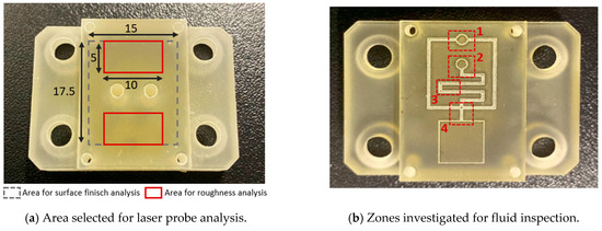
Figure 3.
Scheme for data acquisition for (a) flat and (b) fluid tests.
An inspection analysis of the microfluidic features on the produced resin inserts and samples was carried out, identifying four areas of interest: the upper reservoir (Figure 3(b-1)), lower reservoir (Figure 3(b-2)), inverted microchannel detail (Figure 3(b-3)), and microchannel cross-section (Figure 3(b-4)).
After moulding cycles, the 1st, 2nd, 5th, 10th, 15th, and 20th samples were analysed to observe the effects of the moulding process and possible defects.
3. Results and Discussion
3.1. Analysis of Flat Insert and Produced Samples
After the production of the samples, all the inserts exhibited cracks along their cross-sections (Figure 4a) due to the high pressure involved in the micro injection moulding process and the brittle behaviour of the resin. A test conducted on the inserts used to produce a single sample showed that these cracks appeared after the first shot. This damage, however, seems to have no impact on sample production because the insert is well blocked inside the master plates of the steel mould and remains compact inside its housing. Furthermore, the surface morphology analysis (Section 2.3) showed how the moulding cycle affected the insert cavity. Figure 4 presents the evaluation of the cavity surface flatness for the V00 and V90 inserts before and after sample production (Figure 4b,e). Both bulk inserts maintain flatness in the range of 30 µm, while at the end of the moulding cycle, a convex behaviour of about 100 µm is observed on the surface of both, with the minimum in the centre for V00 (Figure 4c) and close to the running gate for V90 (Figure 4e). This variation in surface flatness highlights the viscoelastic nature of the insert polymer. During the moulding cycles, cavity pressure induces the compression of the insert, increasing its stress levels and leading to permanent deformation, as found by [46]. The interval main plot of Sa and Sz in Figure 5 shows no significant roughness evolution for both inserts before and after the moulding cycle.
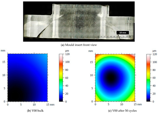
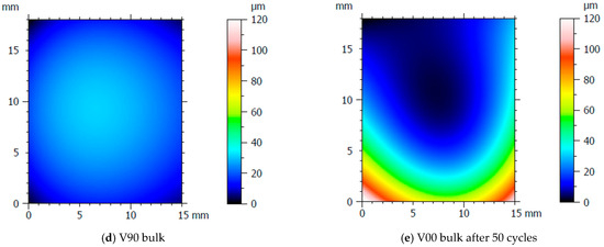
Figure 4.
Analysis of insert flatness variation before and after moulding cycles.
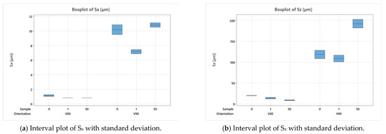
Figure 5.
Analysis of insert roughness evolution before and after moulding cycles.
The results of the visual inspection of both inserts with the V00 and V90 flat surfaces are shown in Figure 6. The absence of sample flash is the result of the improved design discussed in [50] (Figure 6a). Moreover, Figure 6 shows that for both insert geometries tested, the wax residuals (the support material for material jetting) are removed and entrapped in the PMMA (Figure 6b) immediately after the production of the first sample. Samples produced from the V90 insert geometry show a surface sign (Figure 6c): a zone with a parabolic shape. This sign starts to be visible around the 15th sample produced and also shows the flow front of molten polymer during the filling phase. Comparing this sign with the measure of V90 insert flatness in Figure 4e, it seems to correspond with the area where the deflection of the insert begins to be higher.
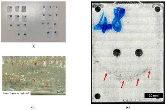
Figure 6.
Main results of visual inspection of flat samples. (a) General overview of samples produced with V00 (left) and V90 (right) inserts. (b) First sample boundary produced with V00 insert. (c) Top view of 48th sample produced with V90 insert.
The results of the sample shape and thickness are summarised in Figure 7. It can be seen that the produced samples have a thickness higher than the designed one of 0.8 mm, with a decreasing trend along the filling direction (Figure 7a) for almost both V00 and V90 inserts (Figure 7b). This variation can be attributed to the higher effect of the injection pressure on the first part of the cavity and the viscoelastic behaviour of the resin insert, resulting in a higher compression of the insert and, consequently, a variation in sample thickness.
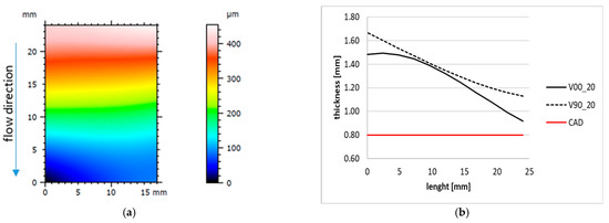
Figure 7.
Sample form and thickness variation along the longitudinal axis. (a) Tenth sample form produced with insert V90. (b) Example of longitudinal trend for 20th samples produced with V00 and V90 insert geometry.
The analysis of the surface roughness of the 1st and 50th samples produced with the V00 and V90 insert configurations (Figure 8) showed an improvement in the surface roughness of all samples, especially for those moulded with the V90 insert (from 50 µm to about 40 µm). The orientation of the inserts on the print plate significantly affects the quality of the samples in terms of surface roughness and geometry. The V90 inserts have a bottom surface cavity belonging to the y-z plane, allowing the layering effect found in the z direction on each part produced by additive processes (Figure 6c). Moreover, the layering weakens the mechanical properties and leads to higher deformation of the insert, resulting in parts with decreasing thickness. By contrast, the V00 inserts, with the cavity on the x-y plane, guarantee smoother parts with more regular thickness (Figure 7b and Figure 8a).
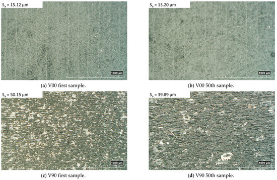
Figure 8.
Top sample morphology with related surface roughness.
3.2. Analysis of Complex Insert and Produced Samples
According to the results obtained from the experiments performed on the flat thin plates, the V00 configuration was selected for the production test of a typical LOC device with a resin insert for microinjection moulding.
Figure 9 shows a general overview of the microstructured insert cavity, with inverted channels having a trapezoidal cross-section and a smaller base size of 200 µm (T200) (Figure 9a), as well as details of the lower circular reservoir (Figure 9b) and of the cross of the microchannels close to the bottom square reservoir (Figure 9c). The residuals of wax, discussed in the previous section, are clearly visible as a white layer all around the microstructures.
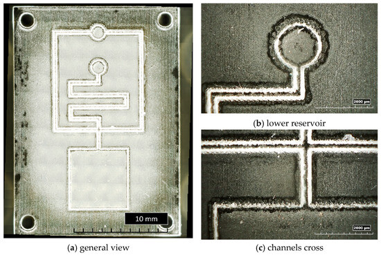
Figure 9.
General and detailed views of bulk insert T200.
In Figure 10, examples of resin inserts with inverted trapezoidal (T300) and semi-circular (S200) microchannels after twenty moulding cycles are shown. All the inserts present the same defects: the generation of a crack along the cross-section (as observed in Figure 4a), a crack on the top surface located in the middle (Figure 10a,c), and the loss of resin along the microstructures and reservoirs of microfluidic features (Figure 10a–d). These defects should be attributed to the high forces involved in the µIM process and the brittle behaviour of the resin, as discussed in Section 3.1.
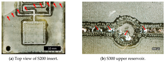
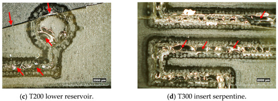
Figure 10.
Overview of the main defects on resin inserts after moulding cycles.
The experimental test showed that the hemispherical channel cross-section was less resistant to the injection moulding process compared to the trapezoid shape. Due to the absence of draft angles, the hemispherical microchannels were under greater stress and had a higher failure rate during the production of the PMMA parts. Additionally, the significance of the position of the microstructures along the insert cavity in relation to the failure mechanism was noted. During µIM, the injection rate increases near the gate and decreases toward the end of the insert cavity due to the pressure loss. As a result, microstructures located closer to the gate are more susceptible to greater damage.
The subsequent analysis of the PMMA samples was useful to identify the number of moulding cycles and, consequently, the part numbers produced before the defects became evident. All samples, except for T200, present evident defects starting from the tenth, whereas T200 presents evident defects from the first one. In Figure 11, it can be seen that the moulded parts have faithfully replicated the insert cavity, exhibiting cracks and irregularities in the channels and pockets due to the damage of the insert microstructures (Figure 11a,b). Figure 11c, in particular, shows the channel shape in Zone 4 of the 1st, 10th, and 20th moulded parts. The change of channel shape is gradual up to the 20th sample, in contrast to the channel depth, which remains constant, around 200 µm as designed. Brittle failure was the dominant failure mode for most inserts. The results also highlighted that the features with the highest aspect ratio (e.g., microchannels) were damaged, as expected, more than those with a lower aspect ratio, such as the bottom square pocket (Zone 4), which showed no defects up to the 20th sample. The experimentation showed that the T300 insert exhibited less damage during moulding cycles than the other configurations tested. The T300 geometry was the most effective in faithfully reproducing the desired microfluidic features on the PMMA moulded parts. Based on these results, the sample parts produced with the T300 insert were considered the most suitable for the preliminary microfluidic tests.
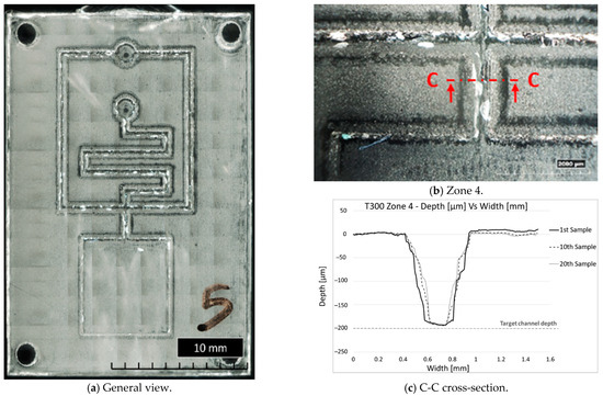
Figure 11.
General and detailed views of fifth sample produced with T300 insert and channel shape during µIM production.
4. Preliminary Microfluidic Tests
To demonstrate the potential of 3D printed technology to prototype microfluidic parts using a mass production approach, preliminary tests on random T300 samples with a typical lab-on-chip geometry have been carried out.
The fabrication of the microfluidic device involved a meticulous process to ensure precise assembly and optimal functionality. The moulded device and a PMMA piece were subjected to a thorough cleaning procedure using sonication with ethanol and hexane, each lasting 30 min. This step aimed to eliminate contaminants and provide a pristine surface for subsequent modifications.
To prevent polymer infiltration into the microfluidic channels, microcontact printing of polydimethylsiloxane (PDMS) was employed on the surfaces of both device components.
Following the printing step, the PDMS underwent partial polymerisation at 55 °C for 35 min, ensuring a stable and adherent coating on the device surfaces. The two device components were then brought into contact under controlled pressure, initiating the subsequent phase of PDMS polymerisation. This final curing step occurred at 150 °C for 1 h and 30 min.
The resulting assembled microfluidic device underwent no further modifications before utilisation. This fabrication process guarantees the integrity of the microfluidic channels and ensures the suitability of the devices for its intended applications. Microfluidic tests with tracer fluid were performed on random T300 samples (shown in Figure 12a).
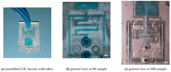
Figure 12.
Preliminary microfluidic tests of 5th and 10th sample produced with microchannel geometry T300.
Figure 12b,c shows the perfect channel filling of the 5th and 10th testers, demonstrating the possibility of using resin inserts for prototyping microfluidic devices with microinjection moulding. Moreover, in Figure 12c, the irregularity of the channels due to insert wear during the moulding cycles can be seen, as discussed in Section 3, which did not compromise the functionality of the device.
5. Conclusions and Perspectives
The proposed work demonstrated the feasibility of utilising additive manufacturing technology, specifically material jetting, for the rapid prototyping of microstructured inserts intended for microfluidic applications with a mass production approach. The technology can generate affordable inserts at a production cost below $10. The preliminary investigation into flat insert geometry aimed to assess improvements in terms of flash reduction and insert robustness during moulding cycles. The results indicated that each flat insert could function effectively for over 50 moulding cycles. However, this production feasibility is significantly diminished when microstructures are incorporated on the cavity surface, as they are susceptible to the injection pressure and filling rate.
Among the cross-sections evaluated for robustness during moulding cycles, the trapezoidal T300 proved to be more competitive. This geometry features a small base size of about 300 µm and an angle at the large base of approximately 60 degrees, providing enhanced strength to microfeatures. With this configuration, at least 10 parts were successfully produced.
Preliminary microfluidic tests conducted using tracer fluid on the assembled microfluidic device validated the effective functionality of the microchannels.
Future developments will focus on further improvement of the insert geometry to increase its durability. In addition, a process simulation will be implemented, considering the combination of the steel master mould with a resin insert, to evaluate the effective thermal distribution and the resulting rheological behaviour of the polymer. An in-depth study of the process parameters using the design of experiments (DoE) approach in microinjection moulding with resin inserts will be an additional essential step to identify an optimality region for prototyping with microinjection moulding.
Author Contributions
Conceptualization, L.G., B.S. and. G.T.; methodology, L.G., B.S. and G.T.; validation, L.G., B.S., K.I.D. and. G.T.; investigation, L.G., B.S., K.I.D., A.F., A.T., M.S.C., F.F. and. G.T.; resources, L.G. and G.T.; data curation, L.G., B.S., K.I.D. and. G.T.; writing—original draft preparation, L.G., B.S., K.I.D. and. G.T.; writing—review and editing, L.G., B.S. and. G.T.; funding acquisition, G.T. All authors have read and agreed to the published version of the manuscript.
Funding
This research was supported within the framework of the project “TITAN—Nanotechnologies for tumor immunotherapy” of the Axis II—PON Research and Innovation 2014–2020 supported by the Ministry of University and Research—project code ARS01 00906—decree n. 397 of 23 December 2020.
Institutional Review Board Statement
Not applicable.
Informed Consent Statement
Not applicable.
Data Availability Statement
The data presented in this study are available on request from the corresponding author. The data are not publicly available due to privacy.
Conflicts of Interest
The authors declare no conflict of interest.
References
- Mastrangeli, M.; Millet, S.; Partners, T.O.; van den Eijnden-van Raaij, J. Organ-on-Chip in Development:Towards a Roadmap for Organs-on-Chip. Preprints 2019, 2019030031. [Google Scholar] [CrossRef]
- Gupta, S.; Ramesh, K.; Ahmed, S.; Kakkar, V. Lab-on-chip technology: A review on design trends and future scope in biomedical applications. Int. J. Bio-Sci. Bio-Technol. 2016, 8, 311–322. [Google Scholar] [CrossRef]
- Azizipour, N.; Avazpour, R.; Rosenzweig, D.H.; Sawan, M.; Ajji, A. Evolution of biochip technology: A review from lab-on-a-chip to organ-on-a-chip. Micromachines 2020, 11, 599. [Google Scholar] [CrossRef] [PubMed]
- Goole, J.; Amighi, K. 3D printing in pharmaceutics: A new tool for designing customized drug delivery systems. Int. J. Pharm. 2016, 499, 376–394. [Google Scholar] [CrossRef]
- Bangaru, S.; Ozorowski, G.; Turner, H.L.; Antanasijevic, A.; Huang, D.; Wang, X.; Torres, J.L.; Diedrich, J.K.; Tian, J.H.; Portnoff, A.D.; et al. Structural analysis of full-length SARS-CoV-2 spike protein from an advanced vaccine candidate. Science 2020, 370, 1089–1094. [Google Scholar] [CrossRef] [PubMed]
- Ruiz-Álvarez, M.J.; Stampone, E.; Verduras, Y.F.; Gallo, G.; González, M.B.; Cubillo, B.B.; Bencivenga, D.; Della Ragione, F.; Borriello, A. Hypocalcemia: A key biomarker in hospitalized COVID-19 patients. Biomed. J. 2023, 46, 93–99. [Google Scholar] [CrossRef] [PubMed]
- Najjar, D.; Rainbow, J.; Sharma Timilsina, S.; Jolly, P.; De Puig, H.; Yafia, M.; Durr, N.; Sallum, H.; Alter, G.; Li, J.Z.; et al. A lab-on-a-chip for the concurrent electrochemical detection of SARS-CoV-2 RNA and anti-SARS-CoV-2 antibodies in saliva and plasma. Nat. Biomed. Eng. 2022, 6, 968–978. [Google Scholar] [CrossRef]
- Fernandes, R.S.; de Oliveira Silva, J.; Gomes, K.B.; Azevedo, R.B.; Townsend, D.M.; de Paula Sabino, A.; de Barros, A.L.B. Recent advances in point of care testing for COVID-19 detection. Biomed. Pharmacother. 2022, 153, 113538. [Google Scholar] [CrossRef] [PubMed]
- Azzouz, A.; Hejji, L.; Kim, K.H.; Kukkar, D.; Souhail, B.; Bhardwaj, N.; Brown, R.J.; Zhang, W. Advances in surface plasmon resonance–based biosensor technologies for cancer biomarker detection. Biosens. Bioelectron. 2022, 197, 113767. [Google Scholar] [CrossRef]
- Annunziata, M.; Arcadio, F.; Borriello, A.; Bencivenga, D.; Piccirillo, A.; Stampone, E.; Zeni, L.; Cennamo, N.; Della Ragione, F.; Guida, L. A novel plasmonic optical-fiber-based point-of-care test for periodontal MIP-1α detection. Iscience 2023, 26, 108539. [Google Scholar] [CrossRef]
- Pandey, C.M.; Augustine, S.; Kumar, S.; Kumar, S.; Nara, S.; Srivastava, S.; Malhotra, B.D. Microfluidics based point-of-care diagnostics. Biotechnol. J. 2018, 13, 1700047. [Google Scholar] [CrossRef] [PubMed]
- Cong, H.; Zhang, N. Perspectives in translating microfluidic devices from laboratory prototyping into scale-up production. Biomicrofluidics 2022, 16, 021301. [Google Scholar] [CrossRef]
- Volpatti, L.-R.; Yetisen, A.K. Commercialization of microfluidic devices. Trends Biotechnol. 2014, 32, 347–350. [Google Scholar] [CrossRef]
- Ramadan, Q.; Zourob, M. Organ-on-a-chip engineering: Toward bridging the gap between lab and industry. Biomicrofluidics 2020, 14, 041501. [Google Scholar] [CrossRef]
- Crawford, S.A.; Hussain, M.A.; Al-Omran, M.; Forbes, T.L.; Roche-Nagle, G. Temporal Trends of Aortic Custom Medical Device Use in Canada. J. Vasc. Surg. 2017, 66, e82–e83. [Google Scholar] [CrossRef][Green Version]
- Cennamo, N.; Bencivenga, D.; Annunziata, M.; Arcadio, F.; Stampone, E.; Piccirillo, A.; Della Ragione, F.; Zeni, L.; Guida, L.; Borriello, A. Plasmon resonance biosensor for interleukin-1β point-of-care determination: A tool for early periodontitis diagnosis. Iscience 2024, 27, 108741. [Google Scholar] [CrossRef]
- Natalicchio, M.I.; Improta, G.; Zupa, A.; Cursio, O.E.; Stampone, E.; Possidente, L.; Teresa Gerardi, A.M.; Vita, G.; Martini, M.; Cassano, A.; et al. Pyrosequencing evaluation of low-frequency KRAS mutant alleles for EGF receptor therapy selection in metastatic colorectal carcinoma. Future Oncol. 2014, 10, 713–723. [Google Scholar] [CrossRef] [PubMed]
- Sackmann, E.K.; Fulton, A.L.; Beebe, D.J. The present and future role of microfluidics in biomedical research. Nature 2014, 507, 181–189. [Google Scholar] [CrossRef] [PubMed]
- Matellan, C.; del Río Hernández, A.E. Cost-effective rapid prototyping and assembly of poly (methyl methacrylate) microfluidic devices. Sci. Rep. 2018, 8, 6971. [Google Scholar] [CrossRef]
- Yazdi, A.A.; Popma, A.; Wong, W.; Nguyen, T.; Pan, Y.; Xu, J. 3D printing: An emerging tool for novel microfluidics and lab-on-a-chip applications. Microfluids Nanofluidics 2016, 20, 50. [Google Scholar] [CrossRef]
- Lin, T.Y.; Do, T.; Kwon, P.; Lillehoj, P.B. 3D printed metal molds for hot embossing plastic microfluidic devices. Lab Chip 2017, 17, 241–247. [Google Scholar] [CrossRef] [PubMed]
- Hur, D.; Say, M.G.; Diltemiz, S.E.; Duman, F.; Ersöz, A.; Say, R. 3D Micropatterned All-Flexible Microfluidic Platform for Microwave-Assisted Flow Organic Synthesis. ChemPlusChem 2018, 83, 42–46. [Google Scholar] [CrossRef] [PubMed]
- Zhang, N.; Byrne, C.J.; Browne, D.J.; Gilchrist, M.D. Towards nano-injection moulding. Mater. Today 2012, 15, 216–221. [Google Scholar] [CrossRef]
- Guber, A.E.; Heckele, M.; Herrmann, D.; Muslija, A.; Saile, V.; Eichhorn, L.; Gietzelt, T.; Hoffmann, W.; Hauser, P.C.; Tanyanyiwa, J.; et al. Microfluidic lab-on-a-chip systems based on polymers—Fabrication and application. Chem. Eng. J. 2004, 101, 447–453. [Google Scholar] [CrossRef]
- Dempsey, D.; McDonald, S.; Masato, D.; Barry, C. Characterization of stereolithography printed soft tooling for micro injection moulding. Micromachines 2020, 11, 819. [Google Scholar] [CrossRef] [PubMed]
- Wu, W.; Deconinck, A.; Lewis, J.A. Omnidirectional printing of 3D microvascular networks. Adv. Mater. 2011, 23, 178–183. [Google Scholar] [CrossRef] [PubMed]
- Tsao, C.-W. Polymer Microfluidics: Simple, Low-Cost Fabrication Process Bridging Academic Lab Research to Commercialized Production. Micromachines 2016, 7, 225. [Google Scholar] [CrossRef]
- Becker, H.; Gärtner, C. Polymer Microfabrication Methods for Microfluidic Analytical Applications. Electrophor. Int. J. 2000, 21, 12–26. [Google Scholar] [CrossRef]
- Lucyshyn, T.; Des Enffans d’Avernas, L.V.; Holzer, C. Influence of the mold material on the injection moulding cycle time and warpage depending on the polymer processed. Polymers 2021, 13, 3196. [Google Scholar] [CrossRef]
- Gülçür, M.; Couling, K.; Goodship, V.; Charmet, J.; Gibbons, G.J. Rapid tooling: Investigation of soft-tooled micro-injection moulding process characteristics using in-line measurements and surface metrology. Rapid Prototyp. J. 2023, 29, 1420–1437. [Google Scholar] [CrossRef]
- Zhang, N.; Srivastava, A.; Kirwan, B.; Byrne, R.; Fang, F.; Browne, D.J.; Gilchrist, M.D. Manufacturing microstructured tool inserts for the production of polymeric microfluidic devices. J. Micromech. Microeng. 2015, 25, 095005. [Google Scholar] [CrossRef]
- Vieten, T.; Stahl, D.; Schilling, P.; Civelek, F.; Zimmermann, A. Feasibility study of soft tooling inserts for injection moulding with integrated automated slides. Micromachines 2021, 12, 730. [Google Scholar] [CrossRef] [PubMed]
- Gülçür, M.; Wilson, P.; Donnelly, M.; Couling, K.; Goodship, V.; Charmet, J.; Williams, M.A.; Gibbons, G. X-ray computed tomography for predictive quality assessment, 3D visualisation of micro-injection mouldings and soft-tool deformation. Mater. Des. 2023, 227, 111741. [Google Scholar] [CrossRef]
- Van Den Berg, A.; Mummery, C.L.; Passier, R.; Van der Meer, A.D. Personalised organs-on-chips: Functional testing for precision medicine. Lab Chip 2019, 19, 198–205. [Google Scholar] [CrossRef]
- Griffiths, C.A.; Dimov, S.S.; Hirshy, H.; Scholz, S.; Fischer, S.; Spitzbart, M. Prototype tooling for producing small series of polymer microparts. Proc. Inst. Mech. Eng. Part B J. Eng. Manuf. 2011, 225, 2189–2205. [Google Scholar] [CrossRef]
- Stampone, B.; Ravelli, M.; Giorleo, L.; Trotta, G. Thermal behaviour of resin inserts for micro injection moulding: A FEM analysis. Procedia Comput. Sci. 2023, 217, 1360–1369. [Google Scholar] [CrossRef]
- Malek, C.K.; Robert, L.; Michel, G.; Singh, A.; Sahli, M.; Manuel, B.G. High resolution thermoplastic rapid manufacturing using injection moulding with SU-8 based silicon tools. CIRP J. Manuf. Sci. Technol. 2011, 4, 382–390. [Google Scholar] [CrossRef]
- Ali, M.A.; Hu, C.; Yttri, E.A.; Panat, R. Recent advances in 3D printing of biomedical sensing devices. Adv. Funct. Mater. 2022, 32, 2107671. [Google Scholar] [CrossRef] [PubMed]
- Arcadio, F.; Ali, W.; Bencivenga, D.; Del Prete, D.; Marzano, C.; Saitta, L.; Stampone, E.; Cennamo, R.; Carafa, V.; Altucci, L.; et al. 3D-printed biosensors in biomedical applications exploiting plasmonic phenomena and antibody self-assembled monolayers. Biomed. Opt. Express 2024, 15, 1976–1994. [Google Scholar] [CrossRef]
- Bertassoni, L.E.; Cecconi, M.; Manoharan, V.; Nikkhah, M.; Hjortnaes, J.; Cristino, A.L.; Barabaschi, G.; Demarchi, D.; Dokmeci, M.R.; Yang, Y. Hydrogel bioprinted microchannel networks for vascularization of tissue engineering constructs. Lab Chip 2014, 14, 2202–2211. [Google Scholar] [CrossRef]
- Mironov, V.; Kasyanov, V.; Markwald, R.R. Organ printing: From bioprinter to organ biofabrication line. Curr. Opin. Biotechnol. 2011, 22, 667–673. [Google Scholar] [CrossRef] [PubMed]
- Norotte, C.; Marga, F.S.; Niklason, L.E.; Forgacs, G. Scaffold-free vascular tissue engineering using bioprinting. Biomaterials 2009, 30, 5910–5917. [Google Scholar] [CrossRef] [PubMed]
- Weinert, A.; Tormey, D.; O’Hara, C.; McAfee, M. Condition Monitoring of Additively Manufactured Injection Mould Tooling: A Review of Demands, Opportunities and Potential Strategies. Sensors 2023, 23, 2313. [Google Scholar] [CrossRef] [PubMed]
- Scott, S.M.; Ali, Z. Fabrication methods for microfluidic devices: An overview. Micromachines 2021, 12, 319. [Google Scholar] [CrossRef] [PubMed]
- Bagalkot, A.; Pons, D.; Symons, D.; Clucas, D. Analysis of raised feature failures on 3D printed injection moulds. Polymers 2021, 13, 1541. [Google Scholar] [CrossRef] [PubMed]
- Krizsma, S.; Kovács, N.K.; Kovács, J.G.; Suplicz, A. In-situ monitoring of deformation in rapid prototyped injection molds. Addit. Manuf. 2021, 42, 102001. [Google Scholar] [CrossRef]
- Walsh, E.; ter Horst, J.H.; Markl, D. Development of 3D printed rapid tooling for micro-injection moulding. Chem. Eng. Sci. 2021, 235, 116498. [Google Scholar] [CrossRef]
- Gheisari, R.; Bártolo, P.; Goddard, N.; Domingos, M.A.D.N. An experimental study to investigate the micro-stereolithography tools for micro injection moulding. Rapid Prototyp. J. 2017, 23, 711–719. [Google Scholar] [CrossRef]
- Udroiu, R.; Braga, I.; Nedelcu, A. Evaluating the quality surface performance of additive manufacturing systems: Methodology and a material jetting case study. Materials 2019, 12, 995. [Google Scholar] [CrossRef]
- Giorleo, L.; Stampone, B.; Trotta, G. Micro injection moulding process with high-temperature resistance resin insert produced with material jetting technology: Effect of part orientation. Addit. Manuf. 2022, 56, 102947. [Google Scholar] [CrossRef]
- VisiJet M2S-HT250 (MJP). Available online: https://www.3dsystems.com/materials/visijet-m2s-ht250 (accessed on 21 October 2023).
- Trotta, G.; Stampone, B.; Fassi, I.; Tricarico, L. Study of rheological behaviour of polymer melt in micro injection moulding with a miniaturized parallel plate rheometer. Polym. Test. 2021, 96, 107068. [Google Scholar] [CrossRef]
- Attia, U.M.; Marson, S.; Alcock, J.R. Micro-injection moulding of polymer microfluidic devices, Microfluid. Nanofluidics 2009, 7, 1–28. [Google Scholar] [CrossRef]


Disclaimer/Publisher’s Note: The statements, opinions and data contained in all publications are solely those of the individual author(s) and contributor(s) and not of MDPI and/or the editor(s). MDPI and/or the editor(s) disclaim responsibility for any injury to people or property resulting from any ideas, methods, instructions or products referred to in the content. |
© 2024 by the authors. Licensee MDPI, Basel, Switzerland. This article is an open access article distributed under the terms and conditions of the Creative Commons Attribution (CC BY) license (https://creativecommons.org/licenses/by/4.0/).