1. Introduction
Structural health monitoring technology is an important means of structural performance and condition sensing and evaluation that has emerged in recent years. The main method is to use intelligent sensing instruments for the real-time monitoring, dynamic management, and trend analysis of engineering structures. Structural health monitoring can be carried out in real time or regularly to further evaluate the working state, load state, and damage state of engineering structures [
1,
2,
3]. Through structural health monitoring, the health status of the structure can be monitored in real time, and the abnormal behavior of the structure can be identified in time so as to prevent potential structural failures and accidents.
In the field of structural health monitoring, crack monitoring is critical. Cracks will inevitably appear in engineering structures under the combined impacts of external forces, environmental degradation, material deterioration, and unforeseen incidents. Cracks that are too wide will lead to the failure of the protective layer of the concrete structure intended to protect the internal steel bars, causing the corrosion of the steel bars, and then induce other forms of cracks, deformations, and damages. Therefore, cracks can be used as an important index to characterize the structural service performance and safety level.
Cracks are generally caused by the following three factors: the first is the external loads (such as static and dynamic loads) caused by direct stress or structural internal forces; the second is caused by deformation factors (temperature and humidity changes, shrinkage and expansion, uneven settlement of the foundation, etc.); and the third is caused by durability factors (such as steel corrosion, construction process quality, and other factors). The variables in crack monitoring and detection mainly include the crack location, the crack width and length, the crack depth, whether it is stable, whether there is exudate in the crack, the apparent quality of concrete around the crack, and so on. The location, number, and direction of cracks are generally recorded in the form of photographs and drawing fracture development maps. The length is measured with a straight ruler and tape measure, and the width can be measured with a crack width comparison card, a crack width meter, and a feeler ruler. The depth of the crack can be determined by an ultrasonic method or a local chiseling method, and a core sample can be drilled to verify, if necessary.
The crack monitoring method based on traditional manual detection not only is time-consuming and laborious but also has the shortcomings of inaccuracy, incomplete memory, and low efficiency [
4]. There have been many studies on crack monitoring methods. The point monitoring method is the earliest and most widely used method at present. However, in the actual concrete engineering structure, cracks in the concrete structure may not appear at the key points predicted by theory because of the non-uniformity of the material and calculation errors. Because of the limitation of the point monitoring method, distributed sensors have become a new means of crack monitoring. The commonly used crack monitoring methods are ultrasonic detection, the shock elastic wave method, the acoustic emission detection method, the photographic detection method, sensing instrument monitoring, optical fiber sensor network monitoring, etc. With the rapid development of computer hardware capabilities and intelligent algorithms, crack identification algorithms based on deep learning have been widely investigated and applied [
5,
6]. In recent years, as neural networks with deeper layers have been proposed one after another, the accuracy of crack image classification has been getting higher and higher. On the basis of image classification algorithms, object detection has further advanced, and it can not only judge image categories but also use boundary boxes to locate target instances. Compared with traditional image segmentation techniques, the image segmentation algorithm based on deep learning [
7,
8] can directly extract cracks from the original image in an end-to-end manner. Compared with traditional crack monitoring techniques, RFID sensing technology is wireless, thus avoiding complicated sensor wiring. Also, it can work in a passive manner, which requires little or even no external power. In addition, the cost of RFID-based sensors is generally relatively low.
RFID sensing technology has the advantages of wireless operation and low cost, which makes it highly competitive in the field of structure health monitoring [
9,
10,
11,
12,
13]. Therefore, this study systematically summarizes the research progress of crack monitoring based on RFID technology in recent years. Several RFID-based crack monitoring and detection methods are systematically summarized. In addition, for RFID-based crack monitoring applications, the two most commonly used materials are concrete materials and metal materials, which are also illustrated in detail.
2. Crack Monitoring Based on Chipless RFID Technology
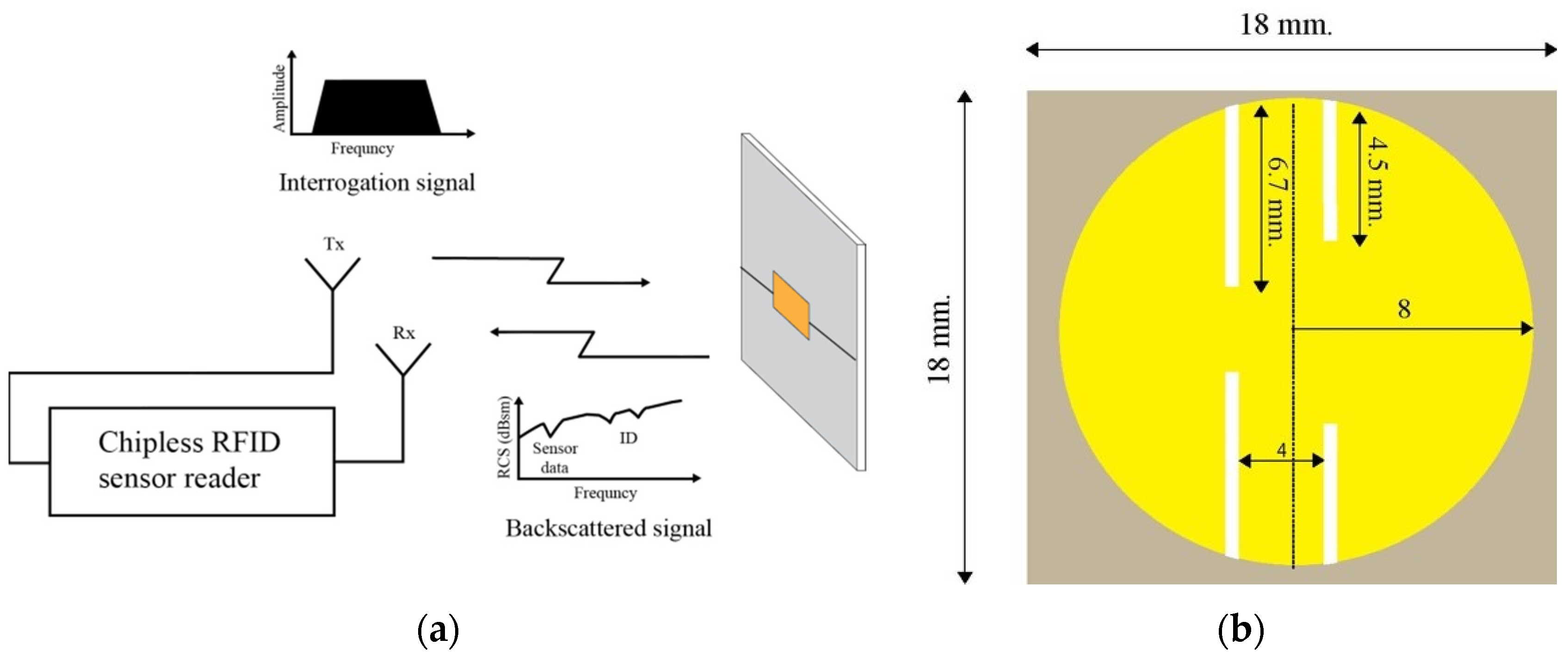
Chipless RFID technology refers to an RFID tag that does not contain a silicon chip. Chipless RFID technology has the advantage of low cost and can also store enough data. In addition, chipless RFID technology can achieve high-speed printing production. Chantasen et al. [
14] proposed chipless RFID tags for crack monitoring, as shown in
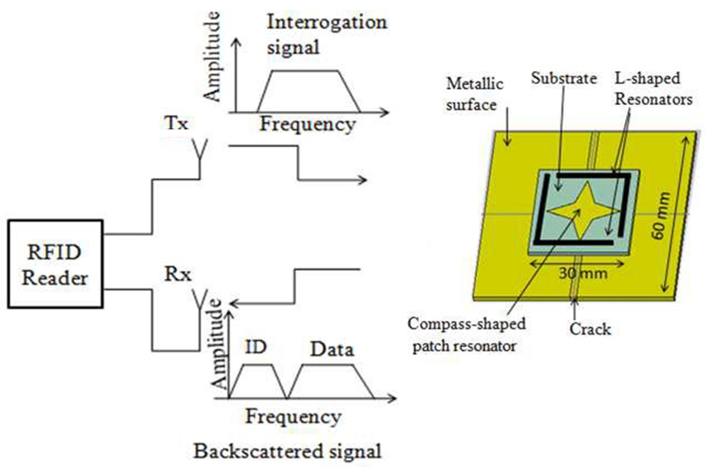
Figure 1. The main part of the tag is the circular microstrip patch antenna (CMPA) resonator. In order to use the bit ID of the resonant frequency indicator tag, a slot is created in the CMPA resonator. The results show that the cracks in the metal will affect the natural frequency shift. Kumar and Patre [
15] designed a chipless RFID sensor tag array to be applied for crack detection on large metal surfaces, as shown in
Figure 2. A single sensor tag contains a compass shape and a pair of L-shaped resonators. In order to identify the crack location, a series array with five rectangular resonators of different sizes is proposed to generate multiple resonant frequencies. Chompoosawat et al. proposed a chip-free RFID sensor, which can be attached to metal plates for crack detection [
16]. A circular microstrip patch antenna resonator was utilized as the main component of the tag, with slots created within the proposed resonator to generate resonant frequencies indicating the tag’s bit ID. The performance of the chipless RFID sensor for detecting metal cracks was evaluated through simulations. The results showed that the notch in the RCS spectra of the tag sensor shifted when a crack was present on the metal plate.
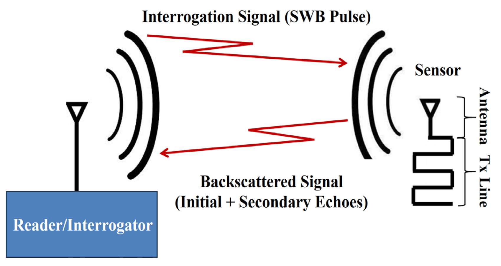
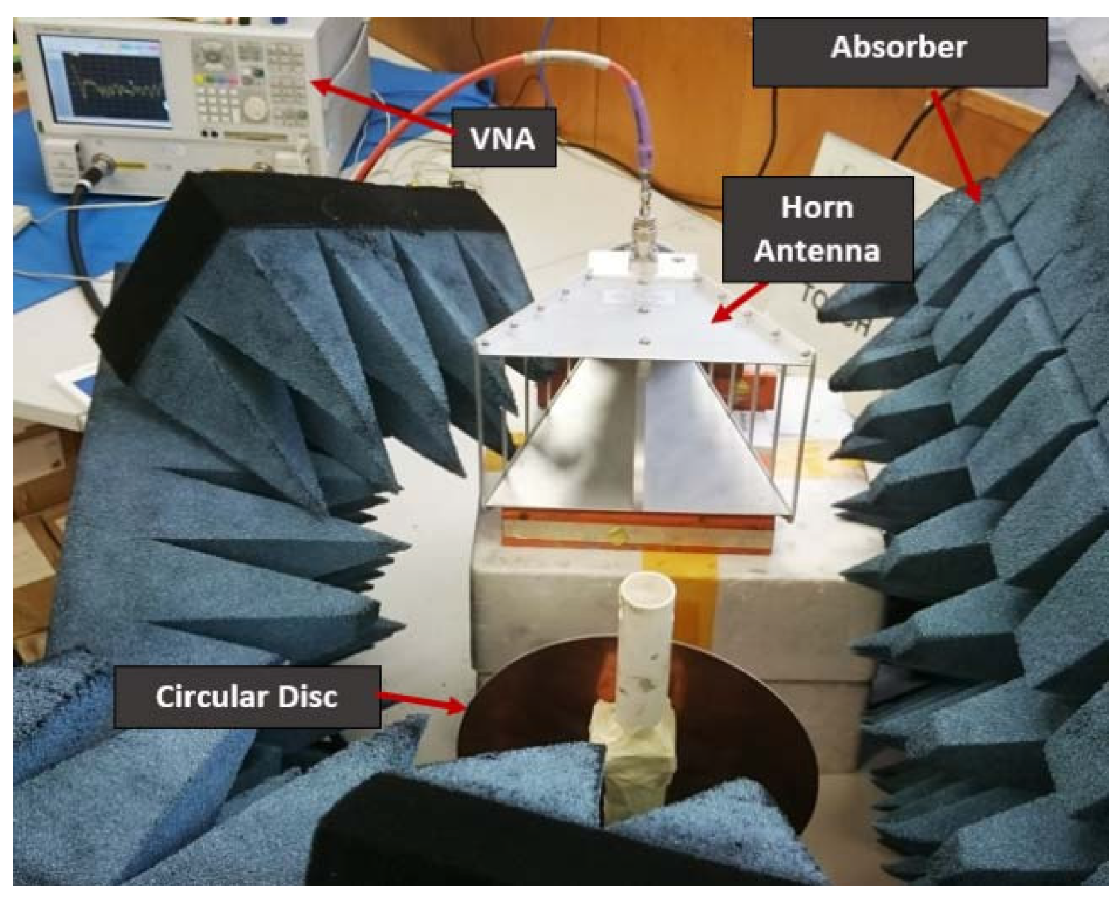
To improve sensor resolution, Dey et al. [
17] proposed a novel chipless RFID sensor that provides a high-resolution crack detection technology capable of achieving ubiquitous wireless crack sensing with high precision (as shown in
Figure 3 and
Figure 4). Using time-domain reflectometry (TDR) technology, the proposed sensor facilitates a wireless, cost-effective sensing system with broad coverage for crack detection. The proposed sensor employs a super-wideband (SWB) antenna operating within the 1–20 GHz range, offering high resolution due to its exceptionally short time-domain pulse. An in-depth examination of the computational findings was conducted, and a comparative evaluation between SWB and UWB sensors was executed to underscore the superiority of the proposed sensor.
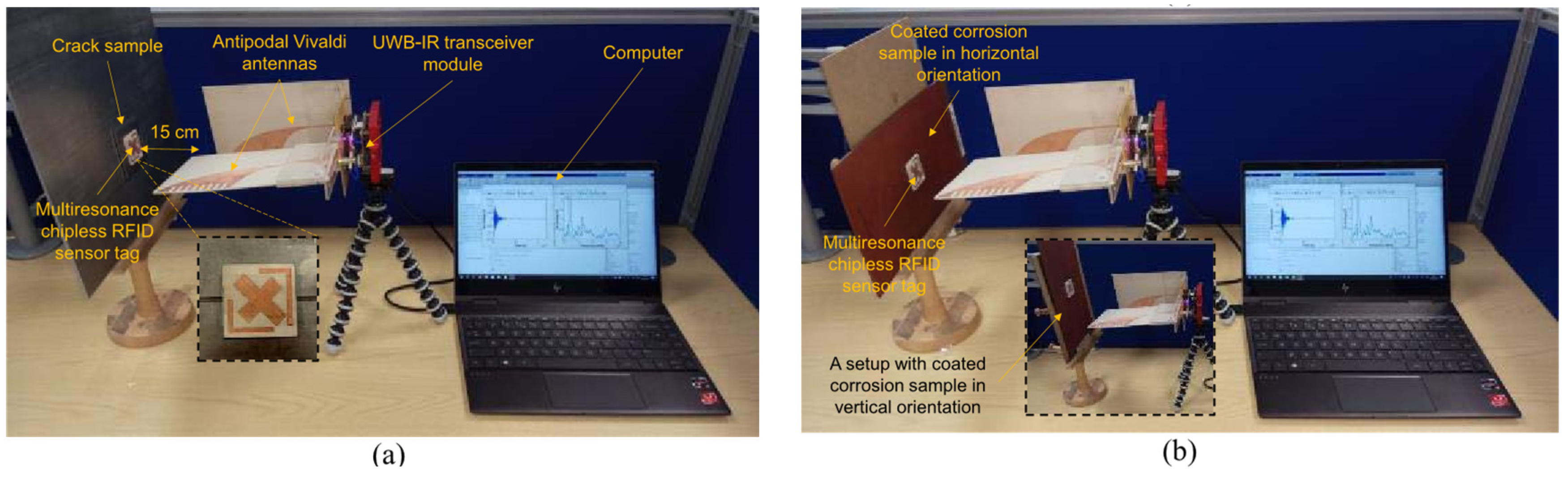
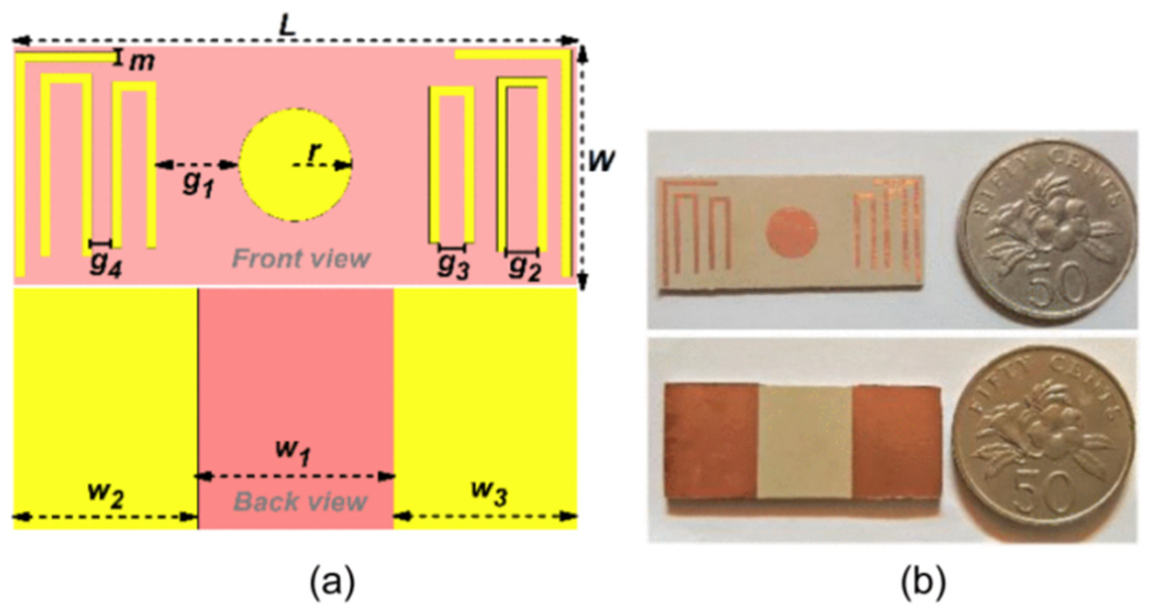
In addition, some scholars have also proposed chipless RFID sensors with multi-sensing functions. Marindra et al. [
18] proposed a multi-resonant chipless RFID sensor tag and a chipless RFID sensor reader for the multi-parameter estimation of metal defect characterization using principal component analysis (PCA) (as shown in
Figure 5). The resonance peaks are within the 2–6 GHz band for metal defect characterization. The sensor tag is combined with a chipless RFID reader using an ultra-wideband impulse radar transceiver module and PCA for multi-parameter estimation. Research has demonstrated that the integration of a multi-resonant chipless RFID sensor tag with PCA-based feature extraction and selection techniques can effectively characterize metal cracks of varying widths and orientations. Javed et al. [
19] presented a compact 7-bit chipless RFID multi-parameter sensor designed with smart materials (as shown in
Figure 6). The dielectric properties of this smart material vary with temperature fluctuations. Circular microstrip patch antennas were utilized to characterize the cracks. The resulting smart sensor can be affixed to any crack on a metal surface.
3. Crack Monitoring Based on Passive RFID Technology
Passive RFID technology sensors have received much attention in health monitoring. Passive RFID tags generally do not contain batteries. When the passive RFID tag approaches the RFID reader, the antenna transfers the received electromagnetic wave energy as electrical energy to power the tag. Passive RFID sensors have the advantages of small size, light weight, low cost, and long service life, and the disadvantages of this technology are mainly the short transmission distance, usually within a few meters. Pavol et al. [
20] proposed passive RFID tag antennas integrated into aircraft structural glass fiber laminates to detect internal defects (as shown in
Figure 7). The results demonstrated the potential of utilizing RFID sensing in fiberglass composite laminates. Omer et al. [
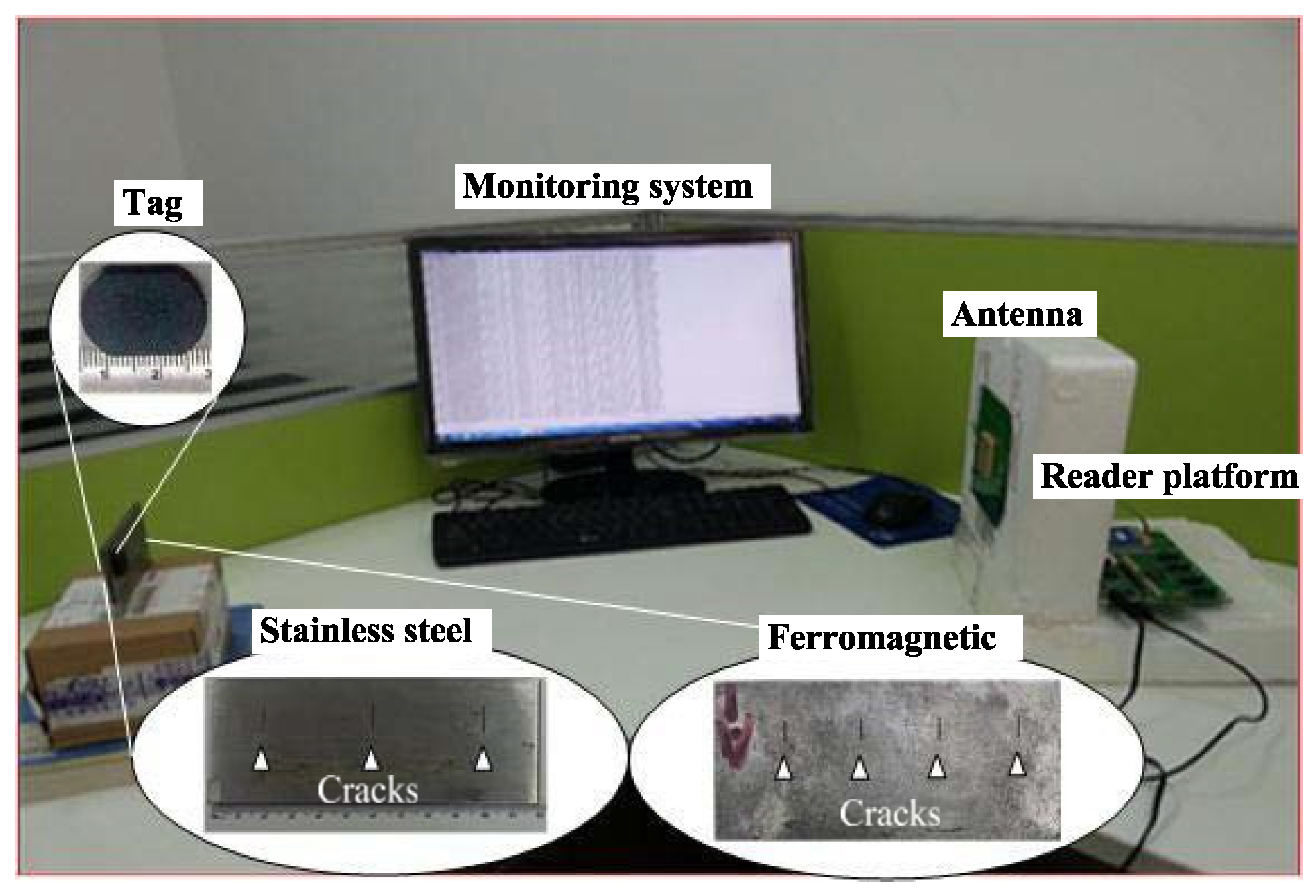
21] developed a new crack depth detection technology based on the ThingMagic M6e platform passive UHF RFID tag (as shown in
Figure 8 and
Figure 9). Wireless power transfer levels and sweep frequencies are used to match tag impedance and metal sensing effects. The distance between the label and the card reader can be adjusted to 30 cm to achieve a high quality factor. As shown in
Figure 8, the existence of peaks within the period is represented by the hit state, and the absence of peaks is represented by the miss state. Thus, all crack states can be encoded as [hit miss hit], while for healthy states, only the miss state occurs, which can be employed to distinguish between healthy and cracked samples. The Power Peak Feature Extraction technique is employed to accurately detect the depth of artificial cracks on the surface of stainless steel and ferromagnetic samples, achieving a maximum error of 0.1 mm. Wen et al. designed a passive RFID tag antenna sensor for crack depth detection. As the metal crack depth increases, the RFID tag resonance frequency moves to a low frequency [
22]. Li et al. designed a new passive RFID patch antenna sensor for strain and crack sensing to improve reliability under temperature fluctuations. Also, in order to obtain a longer interrogation distance, another dual-mode patch antenna sensor was investigated [
23].
In addition, Zhang et al. [
24,
25,
26] have conducted much research on crack monitoring based on passive RFID technology. Zhang et al. [
24] introduced a passive RFID sensor system for crack detection (as shown in
Figure 10). A novel approach utilizing 3D antenna technology was explored and validated through two case studies, i.e., the evaluation of open and closed cracks. In addition, Zhang et al. [
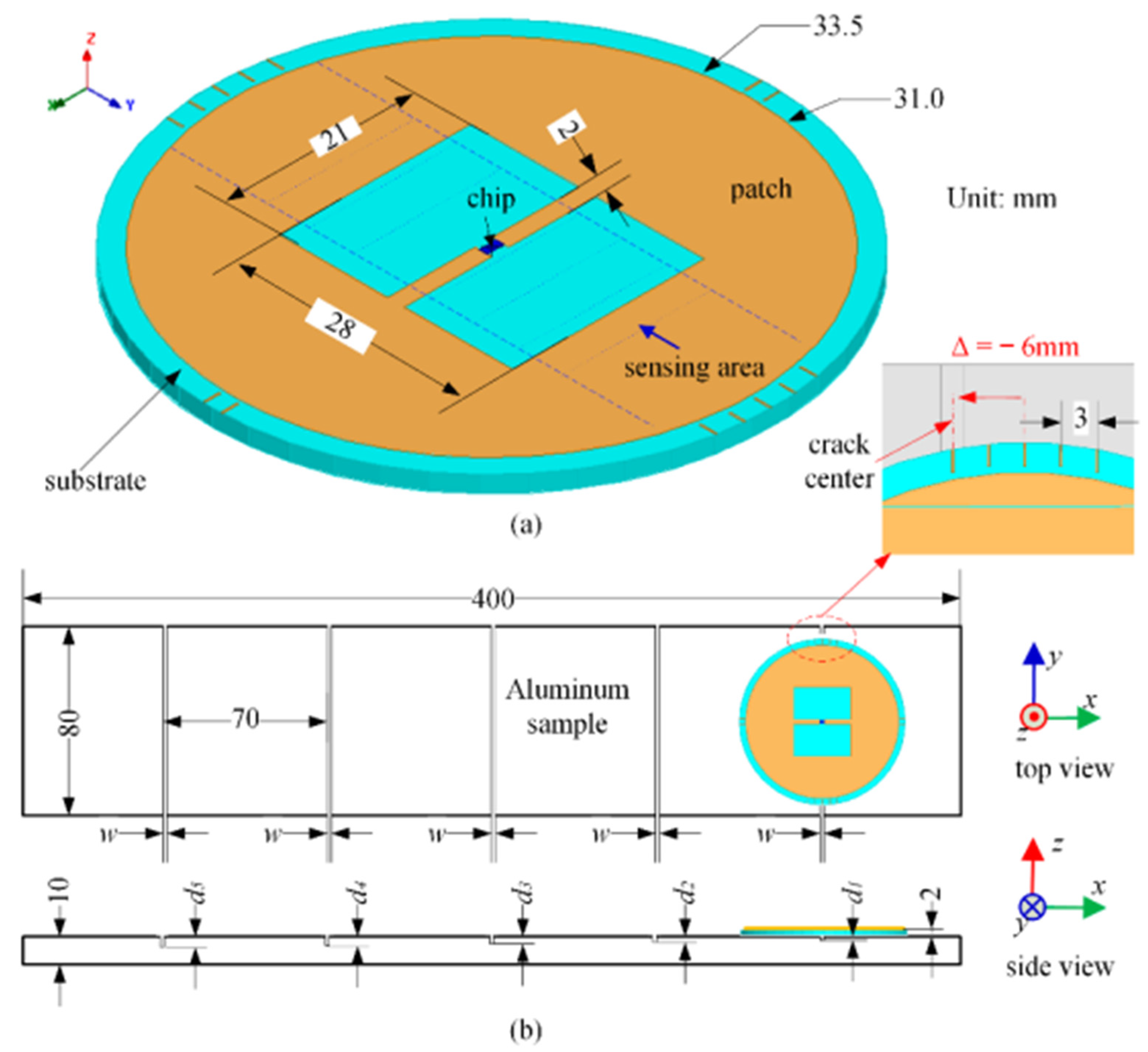
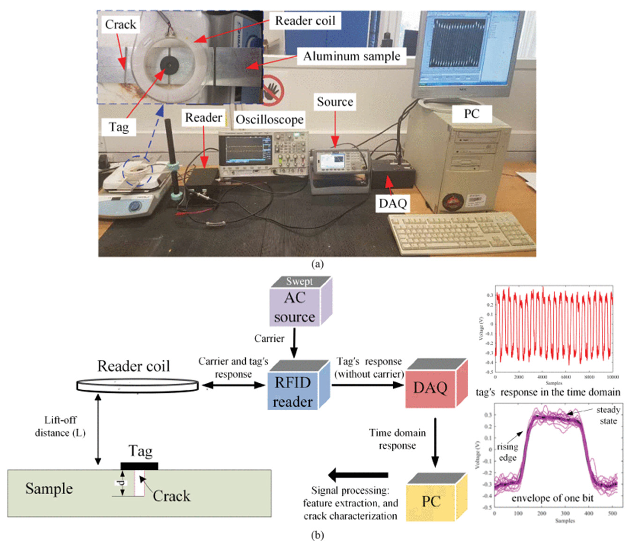
25] used a circular passive RFID patch antenna sensor with an open rectangular window for crack detection (as shown in
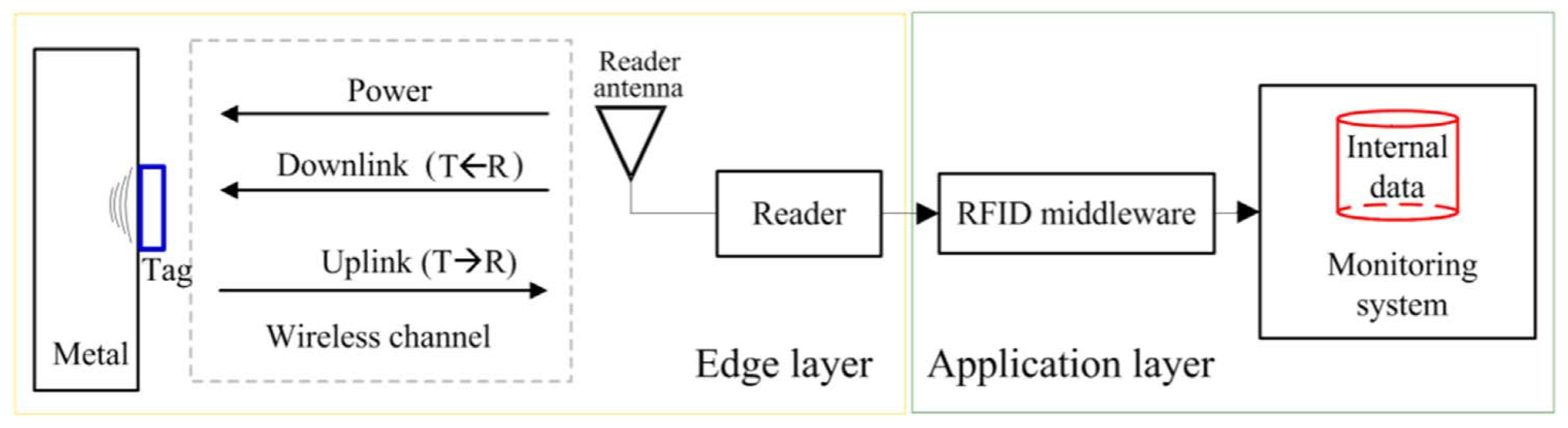
Figure 11). The sensing mechanism was comprehensively studied in tandem with mode analysis, shedding light on the fundamental principle of transforming an antenna into a crack sensor. The robustness was evaluated using varying crack positions on an aluminum sample. In order to improve the robustness of passive wireless RFID antenna sensors, Zhang et al. [
26] reviewed the principle of magnetic resonance coupling communication for passive RFID antenna sensors with low frequency (as shown in
Figure 12). The impact of communication is elucidated and effectively distinguished from perception through two steps: source frequency scanning to capture system behavior and multi-feature extraction, fusion, and selection and the normalization of selected peak-to-peak time-domain features. In this way, the robustness of RFID sensing systems can be improved.
4. Crack Monitoring Based on Ultra-High-Frequency (UHF) RFID Technology
The use of ultra-high-frequency (UHF) RFID tags for defect detection has broad application prospects in structural health monitoring. The transmission rate for UHF RFID technology is fast, the antenna size is small, and it can also read a large number of electronic labels in a short time. However, the penetration of this frequency band is poor, and the environment has a great impact on the use of RFID in ultra-high-frequency bands. Zhang and Tian [
27] proposed the concept of using RFID tag antenna-based sensors (TABS) for crack detection in the UHF band. The primary objective of their study was to simulate and investigate the feasibility, challenges, and underlying principles of crack monitoring using RFID technology. Kalansuriya et al. [
28] described a surface crack antenna reflection sensor: a chipless RFID sensor was developed to enable universal surface crack detection in a wireless manner (as illustrated in
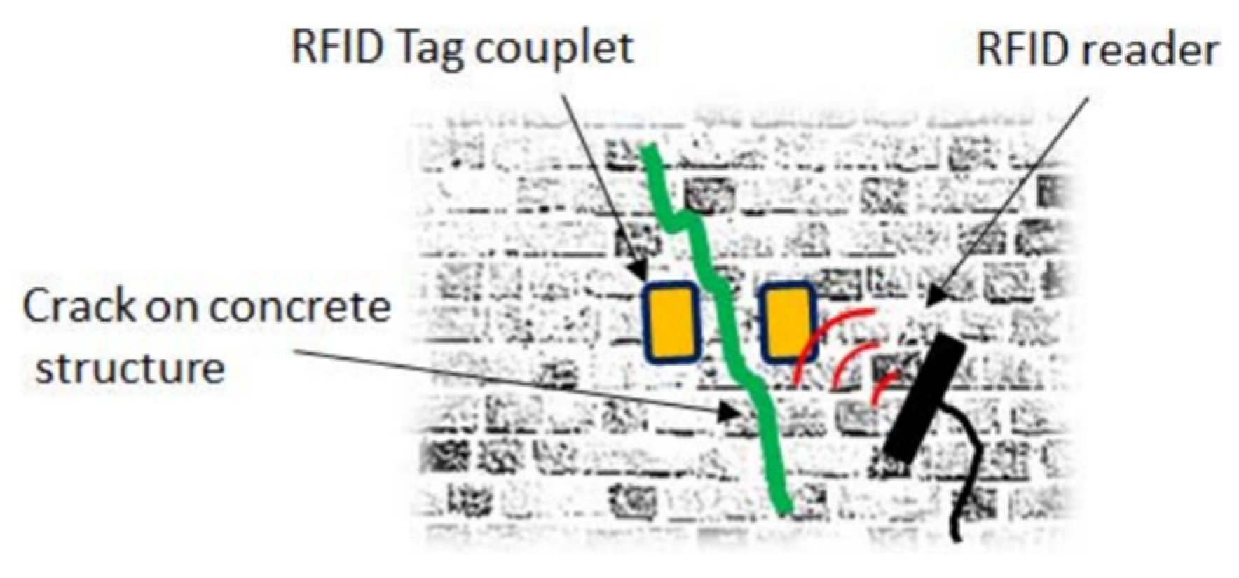
Figure 13). The sensor design was outlined, and it was demonstrated how the crack length and direction are related to the backscattered signal characteristics of the RFID sensor; a design scheme to improve the sensor sensitivity and signal fidelity was proposed. The monitoring system consists of a reader unit and a chipless antenna-based sensor, where the sensor includes a broadband antenna and a meandering transmission line terminated with an open or short circuit. By analyzing the time difference of arrival (TDOA) between two prominent RF echoes, the system can detect the presence of cracks and localize them in a structure. Wang et al. [
29] used a double-label system to monitor cracks in the key structural parts (as shown in
Figure 14). The sensing tag principle and the coupling principle between double tags were investigated. By considering various placements of the two tags, the impact of mutual coupling on the RFID sensing performance of the tags was investigated. Huang et al. introduced an electromagnetically induced transparency-inspired antenna sensor working in the ultra-high-frequency band for surface crack monitoring, with application in structural health monitoring for engineering structures [
30]. The sensor utilizes a split-ring resonator for communication and embeds two back U-shaped strip resonators for sensing in high-dielectric materials, achieving simultaneous communication and sensing within the narrow UHF RFID band. The sensor exhibits enhanced sensitivity, up to five times improvement, attributed to trapped-field dark modes.
In addition, UHF RFID-based crack monitoring has also been successfully applied to the field of mining science. Zohra et al. [
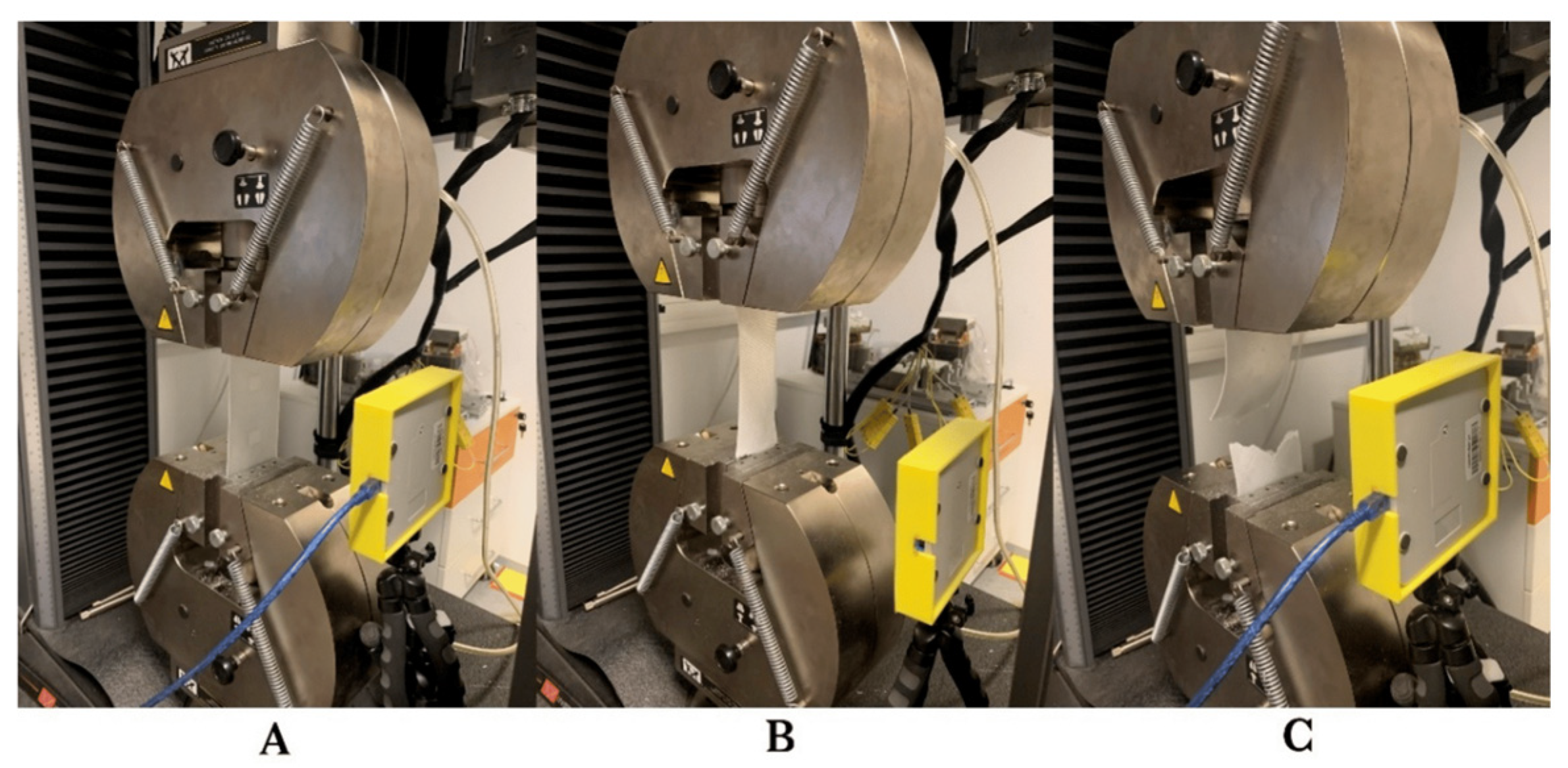
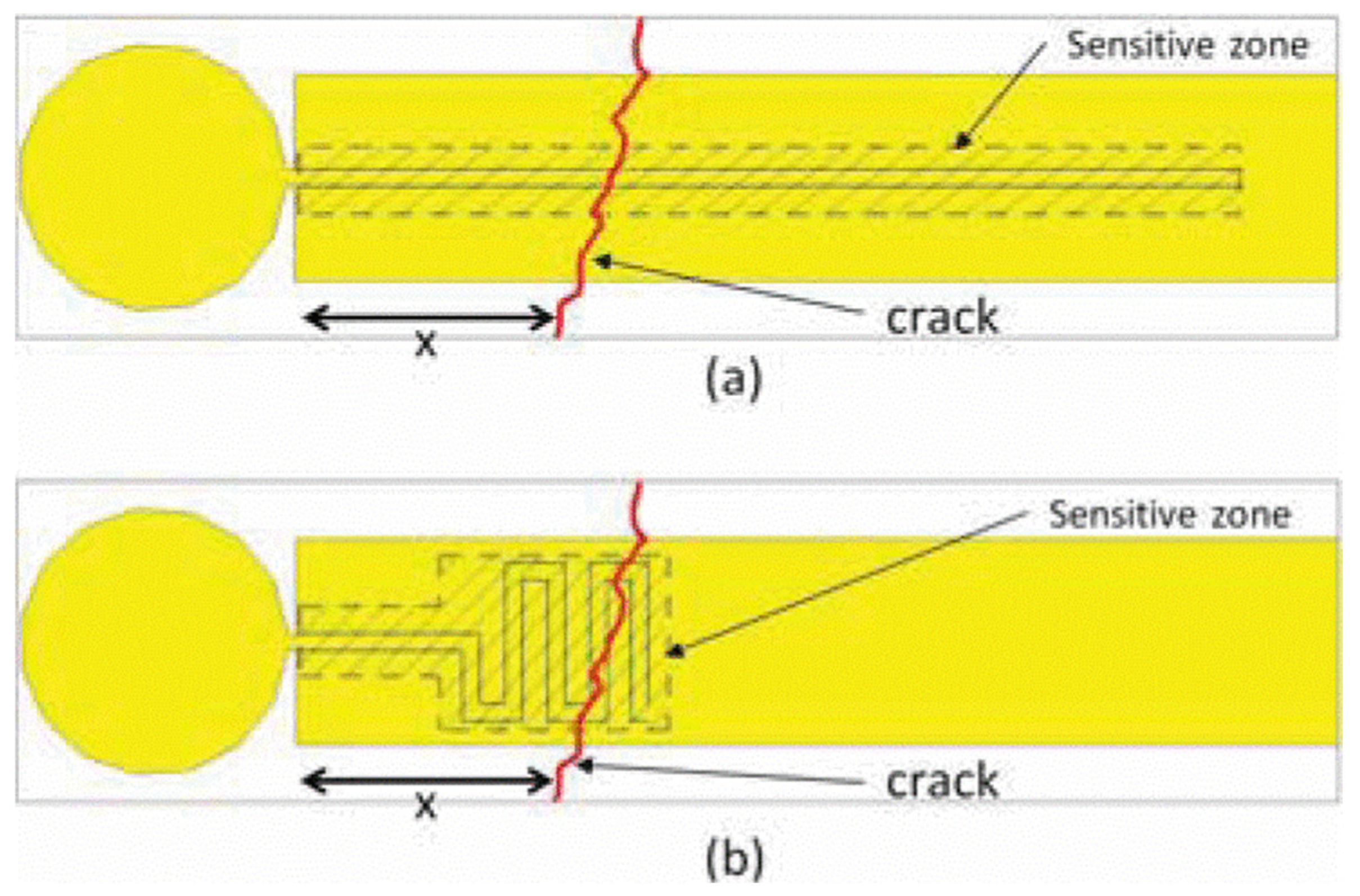
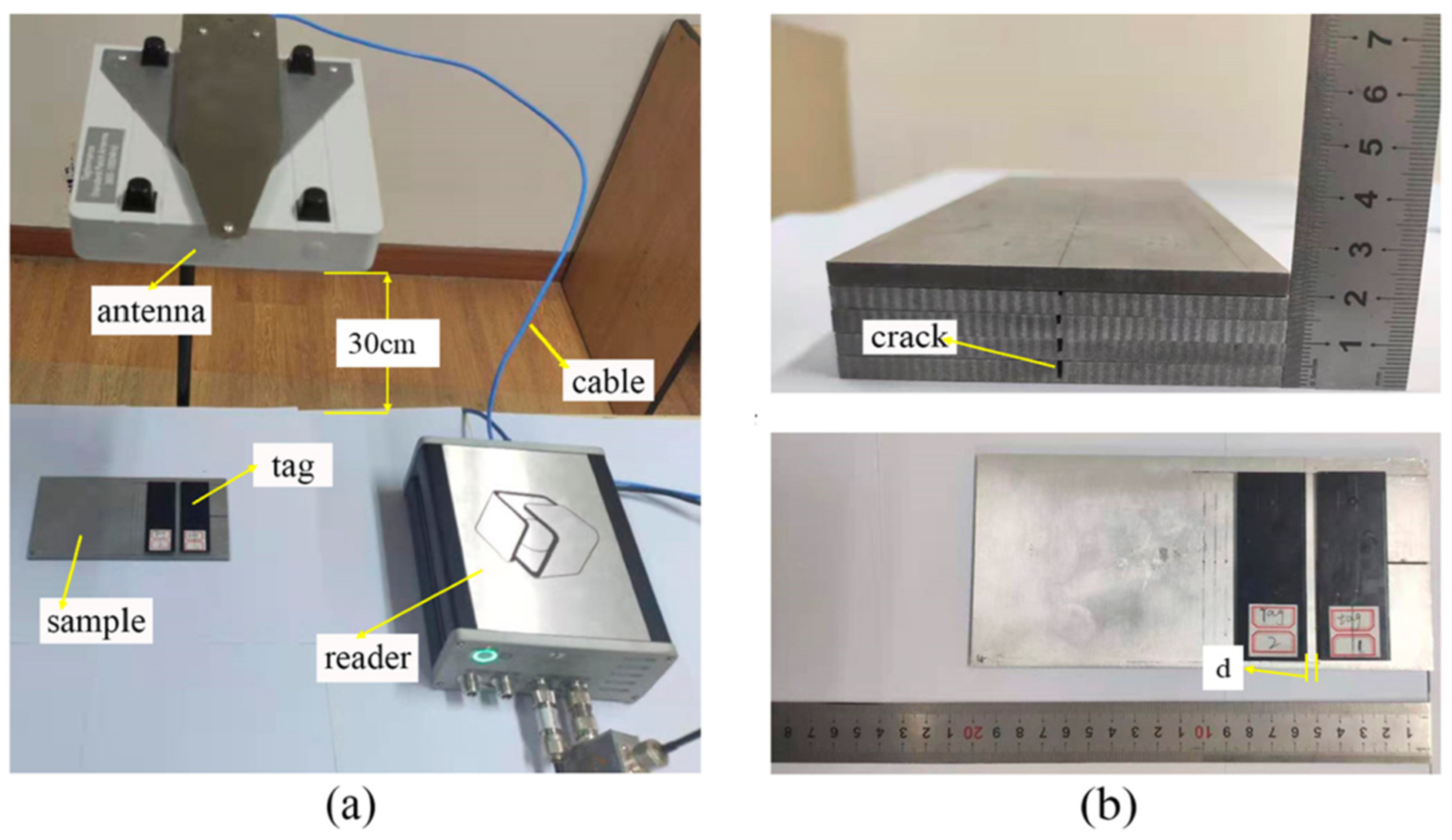
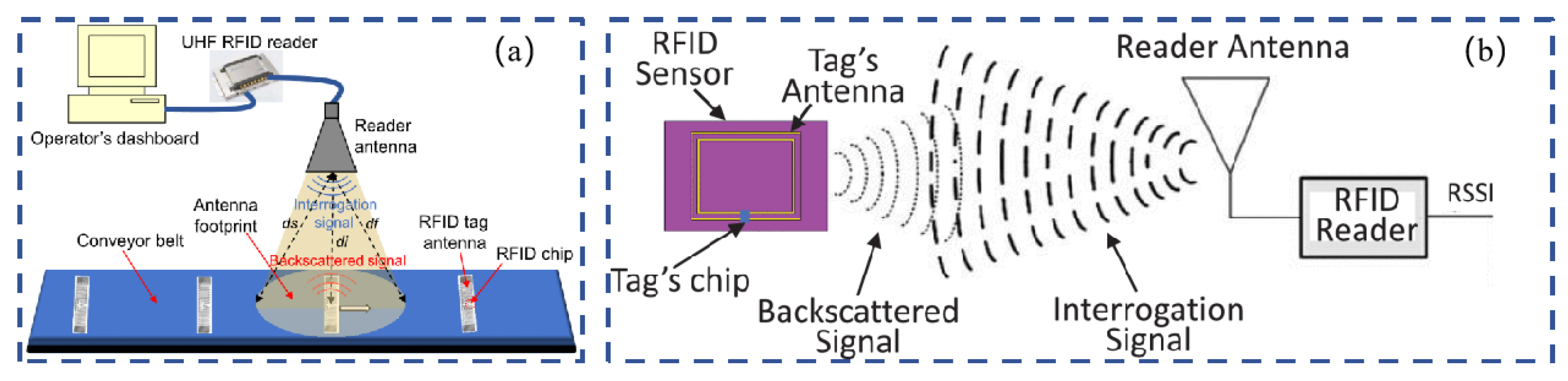
31] proposed a design of a passive UHF RFID tag sensor for monitoring structural cracks in coal mining conveyor belts. Furthermore, a comprehensive comparative analysis was undertaken to assess the influence of different crack orientations and widths. A model integrating RFID-based tags and conveyor belts was designed and simulated to exemplify the practical application of the proposed sensing technique. The results of the simulation demonstrate the feasibility of utilizing the proposed method for the wireless monitoring of cracks in coal mining conveyor belts. Dey et al. [
32] introduced the design and analysis of a new passive UHF RFID crack detection sensor for coal mine conveyor belts (as shown in
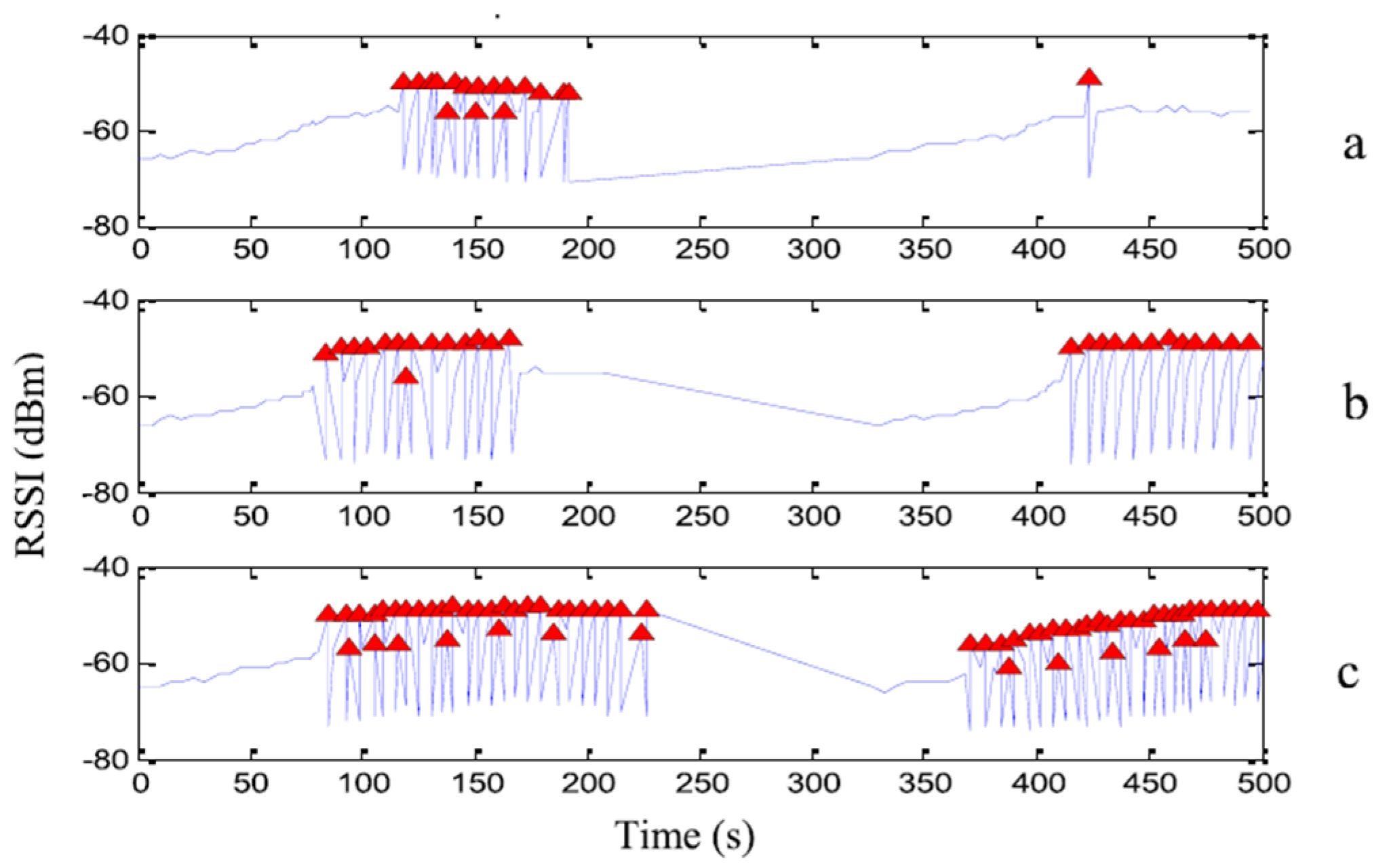
Figure 15), and the proposed sensor was analyzed in detail in simulations and experiments. The experimental results of the prototype sensor finally show the change in the backscattered power of the sensor with the change in the received signal strength index (RSSI). An extensive analysis of the experimental results shows that the proposed sensor can reliably and effectively detect the existence and propagation of cracks as well as variations in the crack width and direction. Salim et al. [
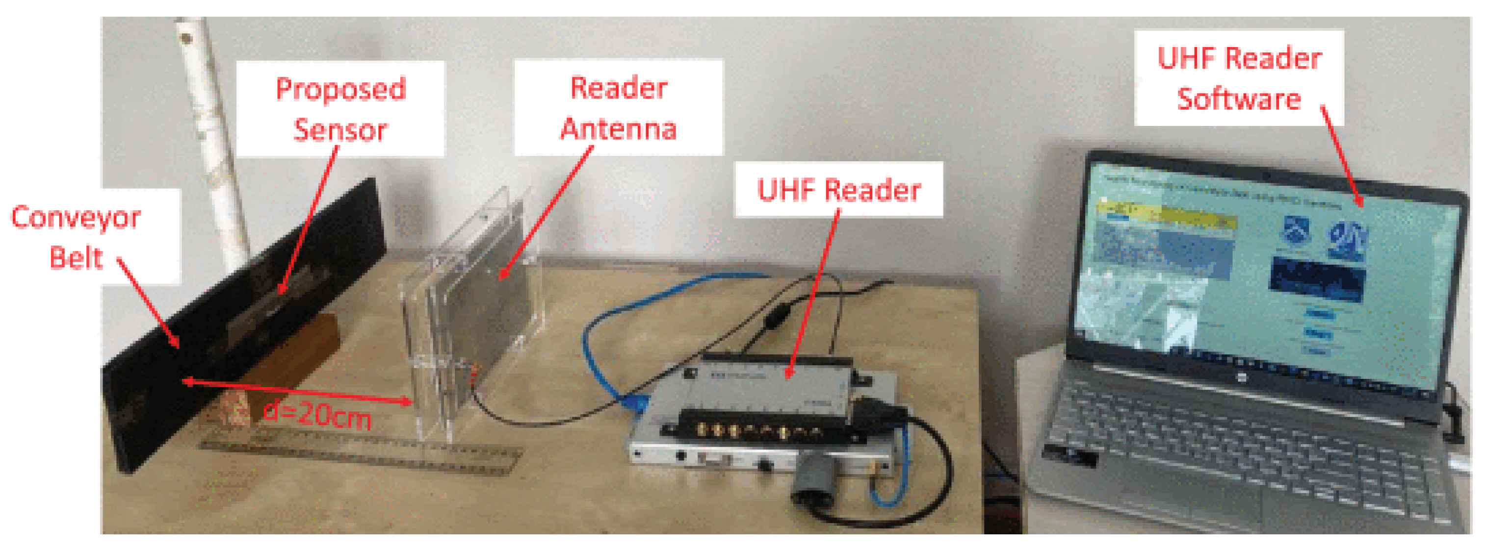
33] proposed a robust and low-cost UHF RFID crack sensing system, which can process and detect cracks in sensor data in real time (as shown in
Figure 16). This study introduced the RSSI theoretical model for when there are cracks in a conveyor belt. RSSI measurement was studied in two cases: when the belt was stationary and moving. The experimental results show that there is a good chance that the proposed system can be used in a real scenario of monitoring the health of a soft rock conveyor belt. The advantages and disadvantages of different RFID crack monitoring technologies are summarized in
Table 1.
5. RFID-Based Crack Monitoring Applications for Concrete Materials
For RFID-based crack monitoring applications, the two most commonly used materials are concrete materials and metal materials. This section mainly introduces how to apply RFID technology to concrete crack monitoring, including monitoring the width and depth of cracks. Pour-Ghaz [
34] employed RFID technology to detect cracks in concrete elements by monitoring changes in the resistance of conductive materials coated on the surface of concrete. When the concrete substrate is subjected to pressure, the conductive material is stretched, and the electrical resistance increases. If the concrete substrate is subjected to enough pressure to crack, the conductive material will also crack, and the resistance will increase significantly. Caizzone [
35] focused on the RIFD-based deformation and crack problems of structures, emphasizing the importance of monitoring them to prevent catastrophic failures and reduce maintenance costs, and discussed the application of sensors in the monitoring of structures, including various physical monitoring principles, sensor types, system designs, signal processing methods, and application areas (as shown in
Figure 17 and
Figure 18). Bruciati et al. [
36] employed RFID-based crack sensing to monitor ultra-high-performance concrete (UHPC) modifications. A crack was simulated on the UHPC sample, and then a commercial low-cost label was obtained (as shown in
Figure 19). The proposed RFID sensors can be used to monitor the small cracks that occur during the creation of UHPC to ensure that the capability of modification is maintained.
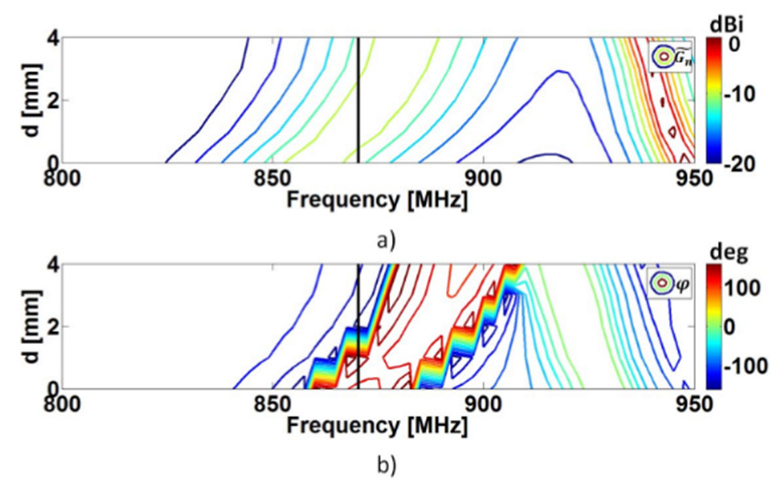
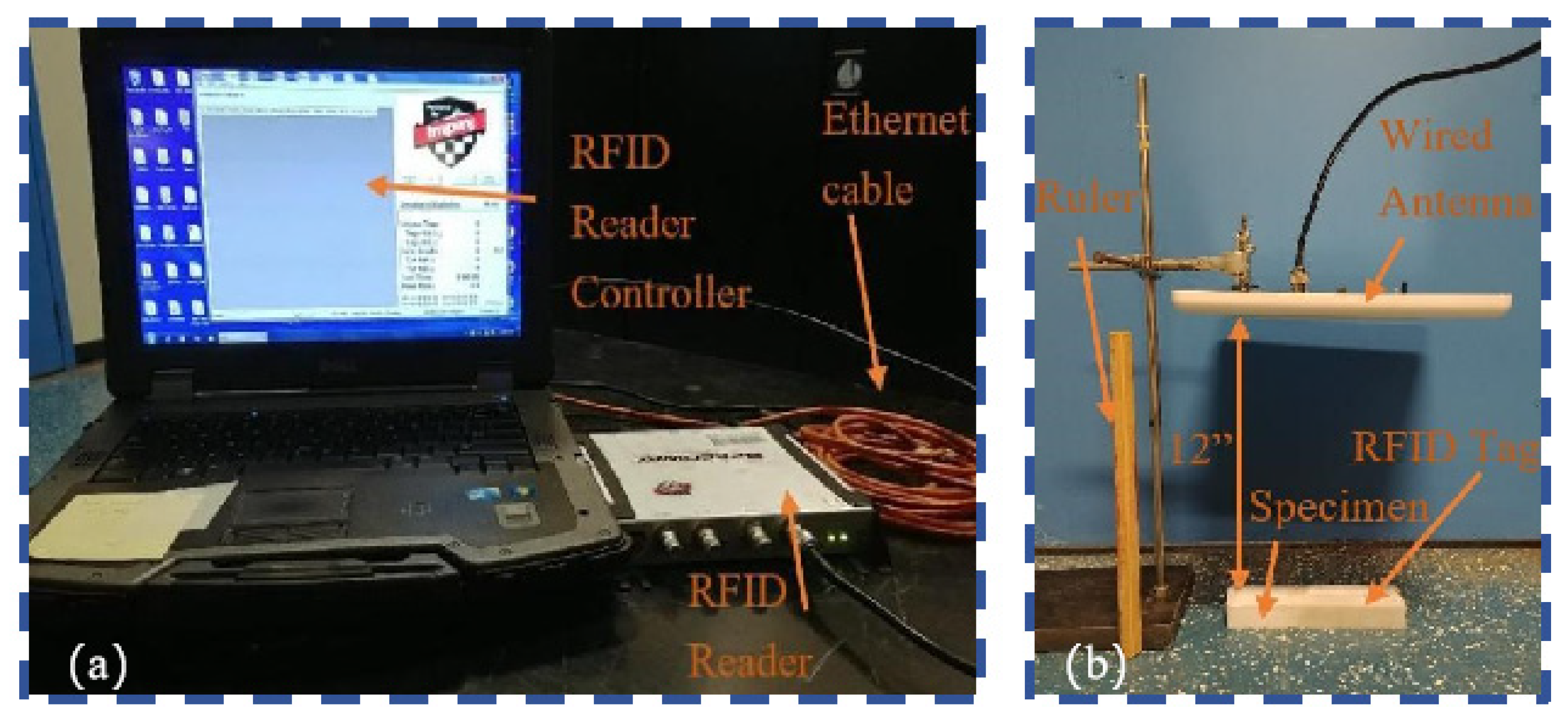
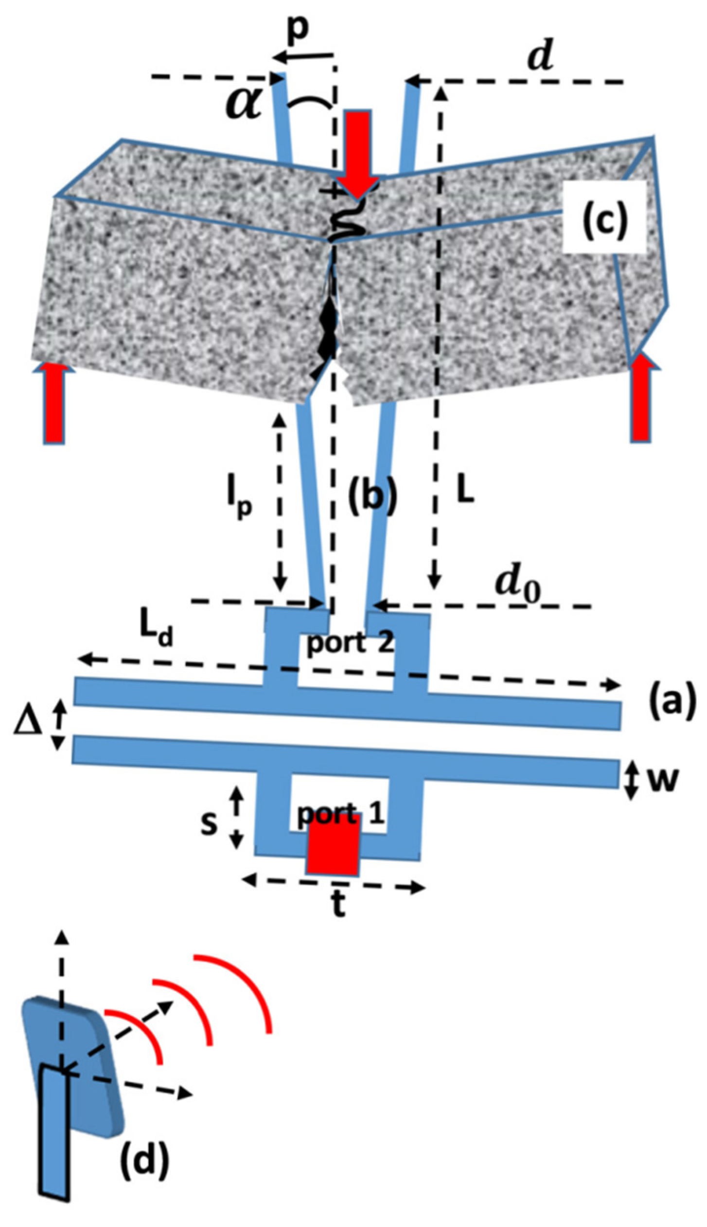
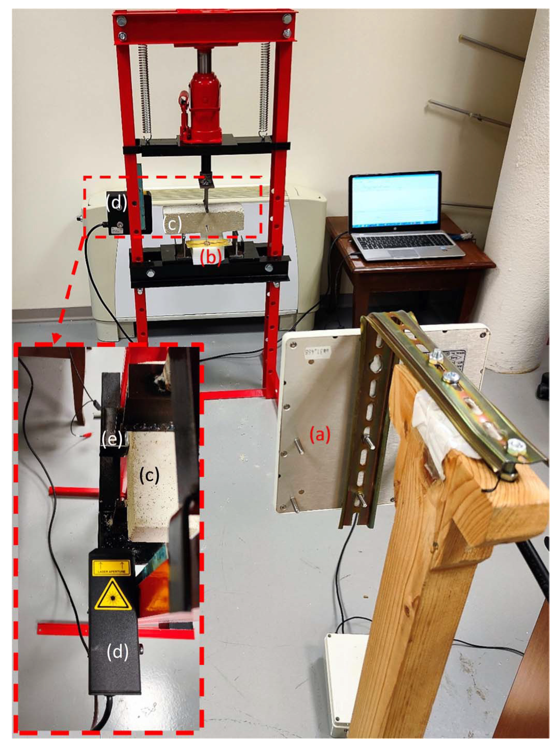
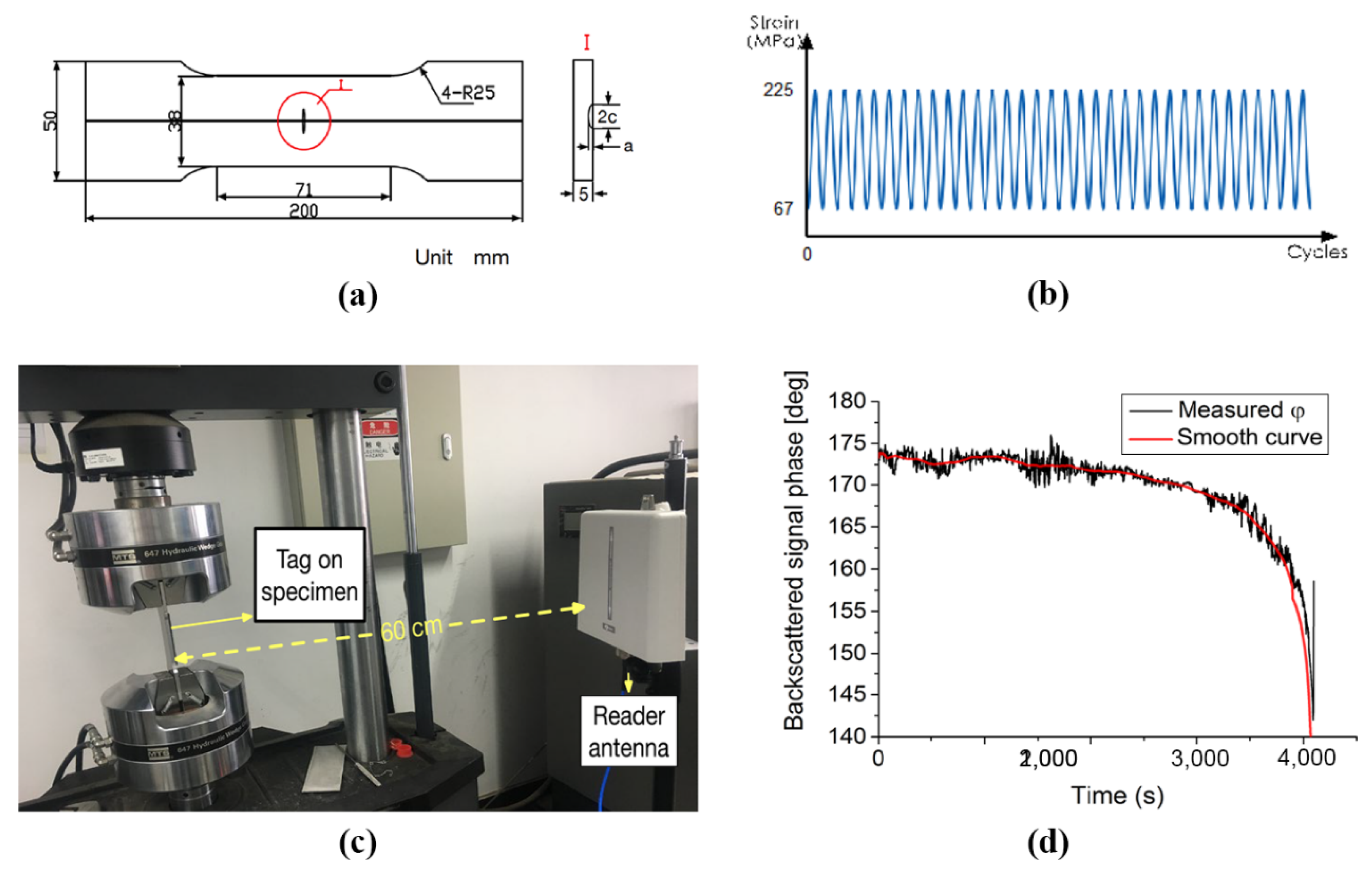
There are also some scholars who carried out research on UHF RFID sensing technology for concrete crack monitoring. DiNatale et al. [
37] introduced a new wireless sensor tag based on passive UHF RFID technology to measure the opening of a crack in concrete materials (as shown in
Figure 20 and
Figure 21) as a phase shift in the signal backscattered from RFID sensor tags. The sensor measures the opening of the crack by detecting the phase variation in the signal backscattered from an RFID tag connected to a load sensitive to changes in crack width. The innovation in the sensor design lies in the use of electromagnetic methods to enhance both the communication stability and sensitivity of the RFID tag. Gunjic et al. [
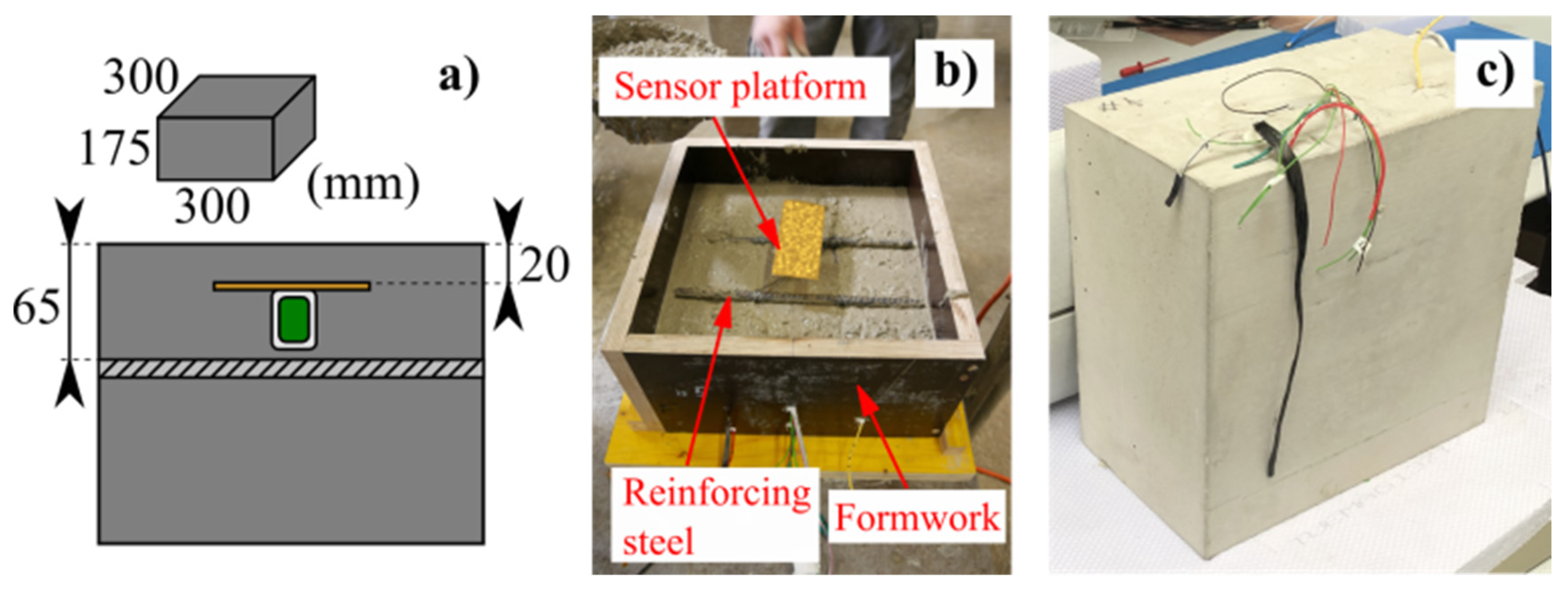
38] discussed the implementation of a passive UHF RFID sensor platform as a measure to prevent cracks in concrete (as shown in
Figure 22). Monitoring data are gathered and transmitted to an RFID reader, where information regarding chlorine concentration is processed. In the proposed RFID sensor platform, enhancements to the RFID sensor tag, including the incorporation of additional circuit components, were also investigated.
6. RFID-Based Crack Monitoring Applications for Metal Materials
In addition to the monitoring of concrete cracks, research on RFID technology for crack monitoring and detection in metal materials has also been extensive [
39,
40,
41,
42,
43]. Li et al. [
44] proposed a structural health monitoring sensor utilizing RFID technology, which incorporated three RFID tags for identification, as well as a circular patch antenna for crack detection. Simulation results indicate that the resonant frequency of the circular RFID patch antenna exhibits sensitivity to both vertical and transverse cracks. Therefore, the resonance frequency offset can be used to detect the location and orientation of the metal crack. Moreover, Li et al. [
45] detected the width and direction of cracks in metal structures, improved the sensitivity and reliability of detection, and designed a dual-polarization chipless RFID sensor based on frequency signals. The results show that the sensor generates two groups of four resonances under the excitation of
x polarization and
y polarization directions. The direction of the metal crack is judged according to the direction of the resonance frequency deviation. The two polarization modes produce eight-bit resonance deviation information for judgment, which can realize the accurate identification of the cracks in various directions. What is more, Mahmud et al. [
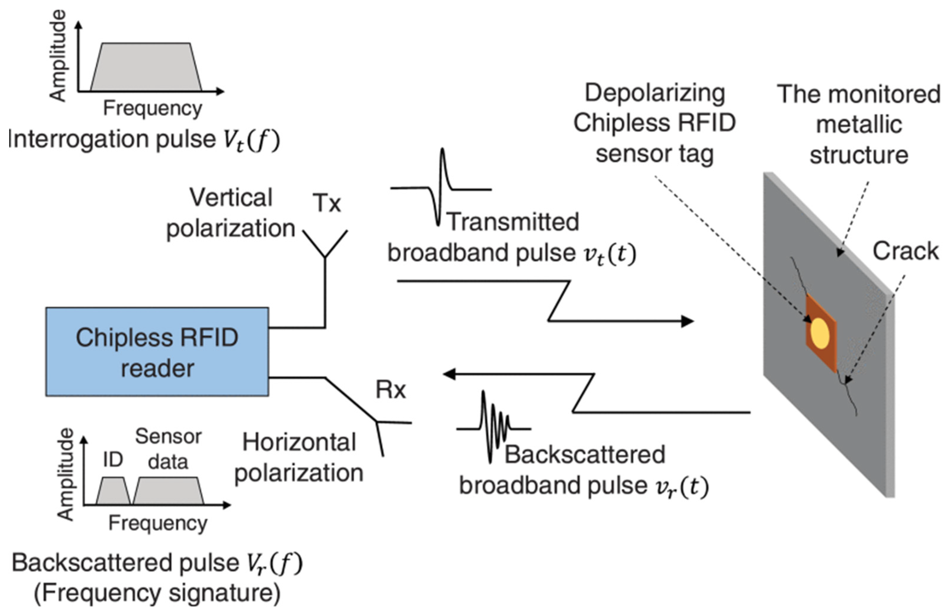
46] introduced a depolarized chipless RFID sensor tag design based on double resonance features for the characterization of metal cracks (as shown in
Figure 23). The proposed sensor integrates a modified circular patch antenna with notched edges for crack detection and diagonal bent dipoles for the RFID tag ID. Experimental results demonstrate that the dual resonance features produced by the depolarizing circular patch can effectively indicate the orientation and monitor the widths of cracks in millimeters. In addition, Mahmud et al. [
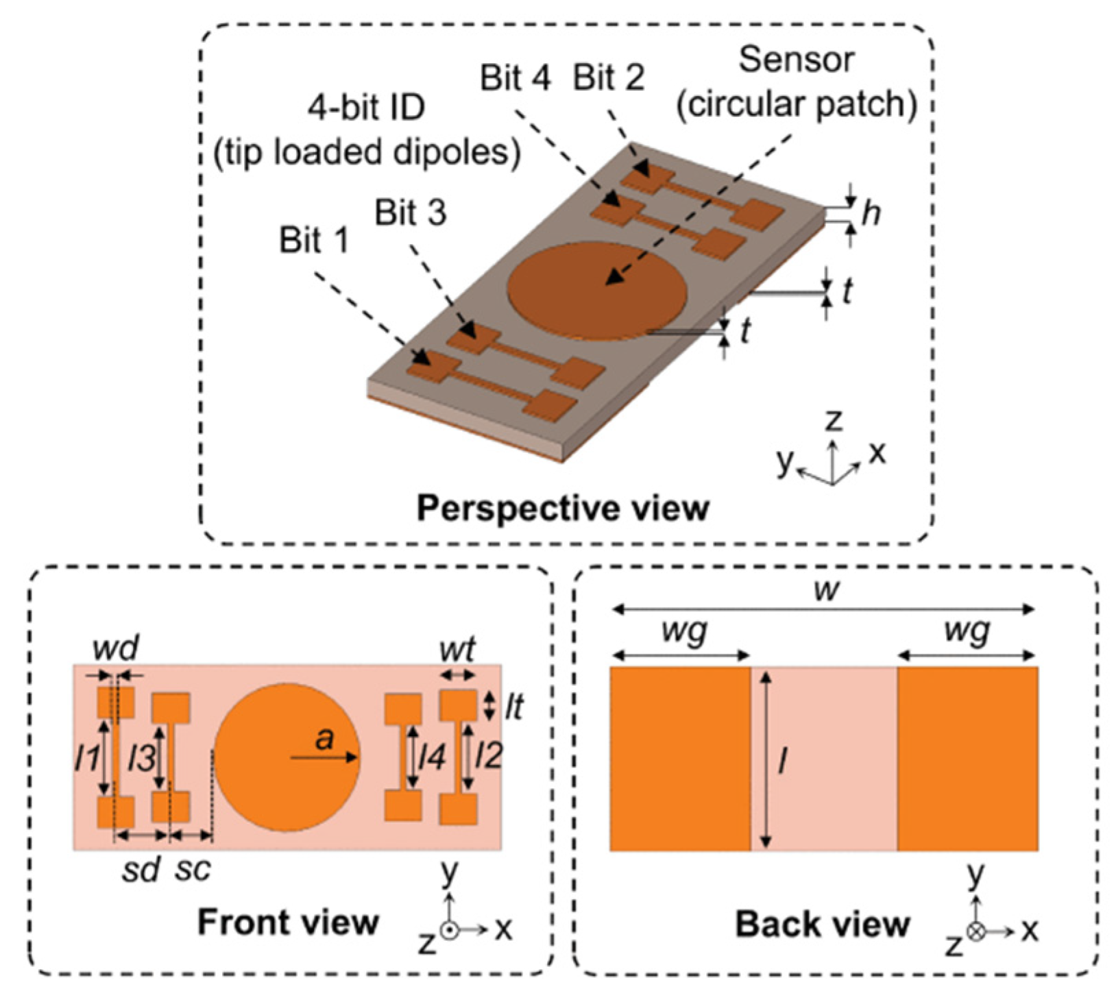
47] proposed a new application of chipless RFID based on frequency characteristics for metal crack detection and characterization at ultra-wideband frequencies (as shown in
Figure 24). The design incorporates four tip-loaded dipole resonators (serving as a 4-bit ID encoder) and a circular RFID patch antenna resonator. Simulation and experimental findings demonstrate that the resonant frequency shift of the proposed sensor is a valuable indicator for determining both the orientation and width of cracks in metallic structures.
In addition, Xu et al. [
48] introduced a surface crack detection and monitoring method based on RFID tags that made the reuse of tags possible (as shown in
Figure 25). Both simulated and experimental outcomes demonstrate that the proposed crack sensing tag can detect surface crack changes with millimeter-level resolution. In addition, the proposed RIFD sensor for crack detection can be reused. Furthermore, Huang et al. [
49] explored the dynamic monitoring capability of surface crack propagation based on an RFID tag sensor, adopted a microstrip tag antenna as the crack sensor, took its backscattered signal as the characterization parameter of crack propagation, and designed a new crack propagation test method. Wang et al. [
50] proposed a novel sensor tag based on a spit ring resonator (SRR) for crack detection on metal surfaces, which is excited by a waveguide to make the tag resonant. Based on the resonant frequency shift caused by the crack, the label can achieve very accurate crack detection. The strong field enhancement effect observed in the spit ring resonator resonance significantly enhances the sensitivity of the label, making it highly effective in metal crack detection. Because the label is flexible, it can be covered with a curved metal surface. On the other hand, Wang et al. [
51] studied the reliability of a passive RFID sensor system with a reference tag in aluminum alloy structural crack detection under conditions of varying reading distance and ambient changes. As the crack depth increases, the sensor tag impedance shifts to the low-frequency direction, and the gain of the proposed sensor exhibits greater sensitivity to variations in crack depth.
7. Conclusions
Cracking is a common hazard in engineering structures, affecting the performance and service life of structures. In order to ensure the safety and reliability of engineering structures, crack monitoring is critical. Crack monitoring based on RFID antennas has the advantages of wireless operation and low cost, which makes them highly competitive in the field of structure health monitoring. This study systematically summarizes the research progress of crack monitoring based on RFID technology in recent years.
Regarding crack monitoring based on chipless RFID technology, a chipless RFID sensor using the circular patch antenna for crack detection is introduced. Also, a new chipless RFID sensor tag array for wireless crack monitoring is presented. SWB technology is employed to obtain a high-resolution chipless RFID crack sensor. In addition, some multi-resonance chipless RFID tags with multi-sensing functions for defect characterization are described.
Passive RFID sensors have the advantages of small size, light weight, low cost, and long service life. This study reviewed a new crack depth detection technology based on a passive RFID tag on the ThingMagic M6e platform. A passive RFID sensor system for crack detection is introduced based on a 3D antenna and kernel principal component analysis. Also, a circular passive RFID patch antenna crack monitoring sensor with an open rectangular window and the principle of magnetic resonance coupling communication for low-frequency passive RFID antenna sensors are illustrated.
For crack monitoring on the basis of UHF RFID technology, this study demonstrated how the crack length and direction are related to the backscattered signal characteristics of the RFID sensor, and a design scheme to improve the sensor sensitivity and signal fidelity is proposed. A double-label UHF RFID system is introduced to monitor cracks in the key structural parts. In addition, UHF RFID-based crack monitoring has also been successfully applied to the field of mining science.
For RFID-based crack monitoring applications, the two most commonly used materials are concrete materials and metal materials. This study introduces RFID-based crack monitoring applications for these two kinds of materials, including monitoring the width and depth of cracks. For concrete crack monitoring based on RFID technology, this study introduces the realization of UHPC beam crack detection based on RFID technology and a new wireless RFID sensor tag to measure the opening of the crack, as well as some UHF RFID sensors for concrete crack monitoring. For metal crack monitoring based on RFID technology, a circular patch antenna that is sensitive to both vertical and transverse cracks is presented, and it can be used to detect the location and orientation of metal cracks. In addition, this article introduced a depolarized chipless RFID sensor tag design based on double resonance features for the characterization of metal cracks, reusable RFID tags for the surface crack detection and monitoring method, and a novel sensor tag based on a spit ring resonator for crack detection on metal surfaces. In general, this study can provide technical support, a reference, and guidance for research on crack monitoring and detection based on RFID technology.
Author Contributions
Conceptualization, S.-C.R. and Q.-A.W.; methodology, S.-C.R. and Q.-A.W.; formal analysis, J.-F.W. and Q.-A.W.; investigation, Z.-X.G. and Y.L.; resources, S.-C.R. and Y.-Q.N.; writing—original draft preparation, S.-C.R., Q.-A.W. and Z.-X.G.; writing—review and editing, S.-C.R., Q.-A.W., J.-F.W. and Y.-Q.N.; supervision, S.-C.R. and Q.-A.W. All authors have read and agreed to the published version of the manuscript.
Funding
This research is funded by the National Natural Science Foundation of China (Grant No. 52008258), the Shenzhen Science and Technology Program (Grant Nos. JSGG20210802093207022 and KQTD20180412181337494), the Shenzhen Key Laboratory of Structure Safety and Health Monitoring of Marine Infrastructures (in preparation, Grant No. ZDSYS20201020162400001), a grant from the Research Grants Council of the Hong Kong Special Administrative Region (SAR), China (Grant No. R5020-18), and a grant from the Innovation and Technology Commission of the Hong Kong SAR Government (Grant No. K-BBY1).
Institutional Review Board Statement
Not applicable.
Informed Consent Statement
Not applicable.
Data Availability Statement
Not Applicable.
Acknowledgments
The authors wish to express their gratitude to the staff and students in the Structural Engineering Laboratory for their extensive assistance.
Conflicts of Interest
The authors declare no conflict of interest.
References
- Wang, Q.A.; Zhang, C.; Ma, Z.G.; Ni, Y.Q. Modelling and forecasting of SHM strain measurement for a large-scale suspension bridge during typhoon events using variational heteroscedasic Gaussian process. Eng. Struct. 2022, 251, 113554. [Google Scholar] [CrossRef]
- Wang, Q.A.; Wang, C.B.; Ma, Z.G.; Chen, W.; Ni, Y.Q.; Wang, C.-F.; Yan, B.-G.; Guan, P.-X. Bayesian dynamic linear model framework for SHM data forecasting and missing data imputation during typhoon events. Struct. Health Monit.—Int. J. 2022, 21, 2933–2950. [Google Scholar] [CrossRef]
- Wang, Q.-A.; Liu, Q.; Ma, Z.-G.; Wang, H.-B.; Wang, J.-F.; Ren, W.-X.; Ni, Y.-Q. Data interpretation and forecasting of SHM heteroscedastic measurements under typhoon conditions enabled by an enhanced Hierarchical sparse Bayesian Learning model with high robustness. Measurement 2024, 230, 114509. [Google Scholar] [CrossRef]
- Liu, Y.F.; Fan, J.S.; Nie, J.G.; Kong, S.Y.; Qi, Y. Review and prospect of digital-image-based crack detection of structure surface. China Civ. Eng. J. 2021, 54, 79–98. [Google Scholar]
- Liu, Y.F.; Nie, X.; Fan, J.S.; Liu, X.G. Image-based crack assessment of bridge piers using unmanned aerial vehicles and three-dimensional scene reconstruction. Comput.-Aided Civ. Infrastruct. Eng. 2020, 35, 511–529. [Google Scholar] [CrossRef]
- Jang, K.; An, Y.K.; Kim, B.; Cho, S. Automated crack evaluation of a high-rise bridge pier using a ring-type climbing robot. Comput.-Aided Civ. Infrastruct. Eng. 2021, 36, 14–29. [Google Scholar] [CrossRef]
- Hang, J.; Wu, Y.; Li, Y.; Lai, T.; Zhang, J.; Li, Y. A deep learning semantic segmentation network with attention mechanism for concrete crack detection. Struct. Health Monit. 2023, 22, 3006–3026. [Google Scholar] [CrossRef]
- Shelhamer, E.; Long, J.; Darrell, T. Fully convolutional networks for semantic segmentation. IEEE Trans. Pattern Anal. Mach. Intell. 2017, 39, 640–651. [Google Scholar] [CrossRef] [PubMed]
- Wang, P.; Dong, L.; Wang, H.; Li, G.; Di, Y.; Xie, X.; Huang, D. Investigation the influence of miniaturized RFID tag sensor on coupling effect. Sens. Rev. 2021, 41, 425–435. [Google Scholar] [CrossRef]
- Zhang, M.; Liu, Z.; Shen, C.; Wu, J.; Zhao, A. A review of radio frequency identification sensing systems for structural health monitoring. Materials 2022, 15, 7851. [Google Scholar] [CrossRef]
- Zhang, B.; Lyu, Y.; Lee, Y.-C. Passive wireless strain and crack sensing using a RFID-based patch antenna. J. Phys. Conf. Ser. 2022, 2198. [Google Scholar] [CrossRef]
- Liu, G.; Wang, Q.A.; Jiao, G.Y.; Dang, P.; Nie, G.; Liu, Z.; Sun, J. Review of Wireless RFID Strain Sensing Technology in Structural Health Monitoring. Sensors 2023, 23, 6925. [Google Scholar] [CrossRef] [PubMed]
- Wang, Q.A.; Zhang, C.; Ma, Z.G.; Jiao, G.Y.; Jiang, X.W.; Ni, Y.Q.; Wang, Y.C.; Du, Y.T.; Qu, G.B.; Huang, J. Towards long-transmission-distance and semi-active wireless strain sensing enabled by dual-interrogation-mode RFID technology. Sructural Control Health Monit. 2022, 29, e3069. [Google Scholar] [CrossRef]
- Chantasen, N.; Shutimarrungson, N.; Boonpoonga, A.; Bannawat, L.; Akkaraekthalin, P. Metal crack detection with chipless RFID sensor using shot-time matrix pencil method. In Proceedings of the 2022 Research, Invention, and Innovation Congress: Innovative Electricals and Electronics (RI2C), Bangkok, Thailand, 4–5 August 2022; pp. 76–79. [Google Scholar]
- Kumar, C.S.; Patre, S.R. Array of chipless RFID sensor tag for wireless detection of crack on large metallic surface. In Proceedings of the 2021 IEEE International Conference on RFID Technology and Applications 2021, Delhi, India, 6–8 October 2021; pp. 142–144. [Google Scholar]
- Chompoosawat, W.; Boonpoonga, A.; Akkaraekthalin, P.; Bannawat, L.; Lertwiriyaprapa, T. Single-layer chipless RFID sensor for metal crack detection. In Proceedings of the International Electrical Engineering Congress 2021, Pattaya, Thailand, 10–12 March 2021; pp. 575–578. [Google Scholar]
- Dey, S.; Kalansuriya, P.; Karmakar, N.C. Novel chipless RFID high resolution crack sensor based on SWB technology. Sensors 2021, 21, 2908–2920. [Google Scholar] [CrossRef]
- Marindra, A.M.J.; Tian, G.Y. Multiresonance chipless RFID sensor tag for metal defect characterization using principal component analysis. Sensors 2019, 19, 8037–8046. [Google Scholar] [CrossRef]
- Javed, N.; Azam, M.A.; Amin, Y. Chipless RFID multisensor for temperature sensing and crack monitoring in an IoT environment. Sens. Lett. 2021, 5, 1–4. [Google Scholar] [CrossRef]
- Pavol, P.; Michal, H.; Andrej, N.; Libor, T. Internal damage detection of composite structures using passive RFID tag antenna deformation method: Basic research. Sensors 2021, 21, 8236. [Google Scholar] [CrossRef] [PubMed]
- Omer, M.; Tian, G.Y.; Gao, B.; Su, D. Passive UHF RFID tag as a sensor for crack depths. IEEE Sens. J. 2018, 23, 9867–9873. [Google Scholar] [CrossRef]
- Wen, H.; Li, Q.; Zhao, L.; Chen, J. Passive RFID tag antenna sensor for metal crack depth detection. Sens. Microsyst. 2022, 41, 81–83. [Google Scholar]
- Li, D.; Wang, Y. Thermally Stable Wireless Patch Antenna Sensor for Strain and Crack Sensing. Sensors 2020, 20, 3835. [Google Scholar] [CrossRef]
- Zhang, J.; Tian, G.Y.; Zhao, A.B. Passive RFID sensor systems for crack detection & characterization. NDTE Int. 2017, 86, 89–99. [Google Scholar]
- Zhang, J.; Huang, B.; Zhang, G.; Tian, G.Y. Wireless passive ultra high frequency RFID antenna sensor for surface crack monitoring and quantitative analysis. Sensors 2018, 18, 2130. [Google Scholar] [CrossRef]
- Zhang, J.; Sunny, A.I.; Zhang, G.; Tian, G.Y. Feature extraction for robust crack monitoring using passive wireless RFID antenna sensors. IEEE Sens. J. 2018, 18, 6273–6280. [Google Scholar] [CrossRef]
- Zhang, J.; Tian, G. An evolution of RFID grids for crack detection. In Proceedings of the 2014 IEEE Far East Forum on Nondestructive Evaluation/Testing (FENDT), Chengdu, China, 20–23 June 2014. [Google Scholar]
- Kalansuriya, P.; Bhattacharyya, R.; Sarma, S.; Karmakar, N. Towards chipless RFID-based sensing for pervasive surface crack detection. In Proceedings of the 2012 IEEE International Conference on RFID-Technologies and Applications (RFID-TA), Nice, France, 5–7 November 2012; pp. 46–53. [Google Scholar]
- Wang, P.; Dong, L.; Wang, H.; Li, G.; Di, Y.; Xie, X.; Huang, D. Passive wireless dual-tag UHF RFID sensor system for surface crack monitoring. Sensors 2021, 21, 882. [Google Scholar] [CrossRef] [PubMed]
- Huang, C.; Huang, B.; Zhang, B.; Li, Y.; Zhang, J.; Wang, K. An electromagnetically induced transparency inspired antenna sensor for crack monitoring. IEEE Sens. J. 2021, 21, 651–658. [Google Scholar] [CrossRef]
- Zohra, F.-T.; Dey, S.; Salim, O.; Masoumi, H.; Karmakar, N. Design and analysis of a UHF RFID crack sensor for health monitoring of mining conveyor belt. In Proceedings of the 2020 27th International Conference on Telecommunications (ICT), Bali, Indonesia, 1–5 October 2020. [Google Scholar]
- Dey, S.; Salim, O.; Masoumi, H.; Karmakar, N.C. A novel UHF RFID sensor based crack detection technique for coal mining conveyor belt. IEEE J. Radio Freq. Identif. 2022, 6, 19–30. [Google Scholar] [CrossRef]
- Salim, O.; Dey, S.; Masoumi, H.; Karmakar, N.C. Crack monitoring system for soft rock mining conveyor belt using UHF RFID sensors. IEEE Trans. Instrum. Meas. 2021, 70, 8003412. [Google Scholar] [CrossRef]
- Pour-Ghaz, M.; Barrett, T.; Ley, T. Wireless crack detection in concrete elements using conductive surface sensors and radio frequency identification technology. J. Mater. Civ. Eng. 2014, 26, 923–929. [Google Scholar] [CrossRef]
- Caizzone, S.; DiGiampaolo, E. Wireless passive RFID crack width sensor for structural health monitoring. IEEE Sens. J. 2015, 15, 6767–6774. [Google Scholar] [CrossRef]
- Bruciati, B.; Jang, S.; Fils, P. RFID-based crack detection of ultra high-performance concrete retrofitted beams. Sensors 2019, 19, 1573. [Google Scholar] [CrossRef] [PubMed]
- DiNatale, A.; DiCarlofelice, A.; DiGiampaolo, E. A crack mouth opening displacement gauge made with passive UHF RFID technology. Sens. J. 2022, 22, 174–181. [Google Scholar] [CrossRef]
- Gunjic, D.; Walk, J.; Fischer, M.; Ussmueller, T. Realization of a passive UHF RFID sensor platform for the detection of damages on a concrete reinforcement. In Proceedings of the 2022 52nd European Microwave Conference (EuMC) 2022, Milan, Italy, 27–29 September 2022; pp. 584–587. [Google Scholar]
- Nappi, S.; Gargale, L.; Naccarata, F.; Valentini, P.P.; Mar-rocco, G. A fractal-RFID based sensing tattoo for the early detection of cracks in implant-ed metal prostheses. IEEE J. Electromagn. RF Microw. Med. Biol. 2022, 6, 29–40. [Google Scholar] [CrossRef]
- Martínez-Castro, R.E.; Jang, S.; Kim, J.; Wentworth, A. Experimental evaluation of a low-cost RFID-based sensor to crack propagation. J. Aerosp. Eng. 2019, 32, 04019003. [Google Scholar] [CrossRef]
- Shiraiwa, T.; Enoki, M. Fatigue crack length measurement of sputtered metal film for rfid-based smart stress memory patch. ISIJ Int. 2011, 51, 1480–1486. [Google Scholar] [CrossRef]
- Wang, L.W.; Ma, Y.B. Design of chip less RFID sensor for detecting crack position on metal surface. J. Test. Technol. 2022, 36. [Google Scholar]
- Wang, C.; Wang, C.; Wan, G.C.; Tong, M.S.; Guan, S.; Xie, L.Y. RFID antenna sensor for quantitatively monitoring surface crack growth. In Proceedings of the 2019 IEEE International Conference on Computational Electromagnetics (ICCEM), Shanghai, China, 20–22 March 2019; pp. 1–3. [Google Scholar]
- Li, M.; Wan, G.; Yang, M.; Tong, M. A chipless RFID sensor for metal crack detection based on notch characteristics. In Proceedings of the 2019 Photonics & Electromagnetics Research Symposium—Fall (PIERS—Fall) 2019, Xiamen, China, 17–20 December 2019; pp. 217–221. [Google Scholar]
- Li, S.; Xue, Y.; Song, Z.; Chen, B. Dual-polarization chipless RFID sensor for metal crack. J. Microw. 2021, 37, 37–43+49. [Google Scholar]
- Marindra, A.M.J.; Sutthaweekul, R.; Tian, G.Y. Depolarizing chipless RFID sensor tag for characterization of metal cracks based on dual resonance features. In Proceedings of the 2018 10th International Conference 2018, Bali, Indonesia, 24–26 July 2018; pp. 73–78. [Google Scholar]
- Marindra, A.M.J.; Tian, G.Y. Chipless RFID sensor tag for metal crack detection and characterization. IEEE Trans. Microw. Theory Tech. 2018, 66, 2452–2462. [Google Scholar] [CrossRef]
- Xu, Y.; Dong, L.; Wang, H.; Xie, X.; Wang, P. Surface crack detection and monitoring in metal structure using RFID tag. Sens. Rev. 2020, 40, 81–88. [Google Scholar] [CrossRef]
- Huang, D.; Dong, L.; Wang, H.; Xu, W.; Zhao, Y.; Wang, H. Research on metal surface crack monitoring based on RFID antenna sensor. Piezoelectric Acoustooptic 2022, 44. [Google Scholar]
- Wang, Z.; Yang, X.; Zhou, X.; Su, P.; Wang, J. A flexible sensor tag for surface crack detection of curved film-coated metals. IEEE Sens. J. 2022, 22, 5662–5668. [Google Scholar] [CrossRef]
- Wang, P.; Dong, L.; Wang, H.; Li, G.; Xie, X. Passive ultra high frequency RFID sensor with reference tag for crack detection of aluminum alloy structure. J. Instrum. 2021, 16, P11018. [Google Scholar] [CrossRef]
| Disclaimer/Publisher’s Note: The statements, opinions and data contained in all publications are solely those of the individual author(s) and contributor(s) and not of MDPI and/or the editor(s). MDPI and/or the editor(s) disclaim responsibility for any injury to people or property resulting from any ideas, methods, instructions or products referred to in the content. |
© 2024 by the authors. Licensee MDPI, Basel, Switzerland. This article is an open access article distributed under the terms and conditions of the Creative Commons Attribution (CC BY) license (https://creativecommons.org/licenses/by/4.0/).


