
Investigation of the Mechanical Features of Steel–Concrete Composite Girder Rigid Frame Bridges with V-Shaped Piers during Construction Stages

Abstract
:1. Introduction
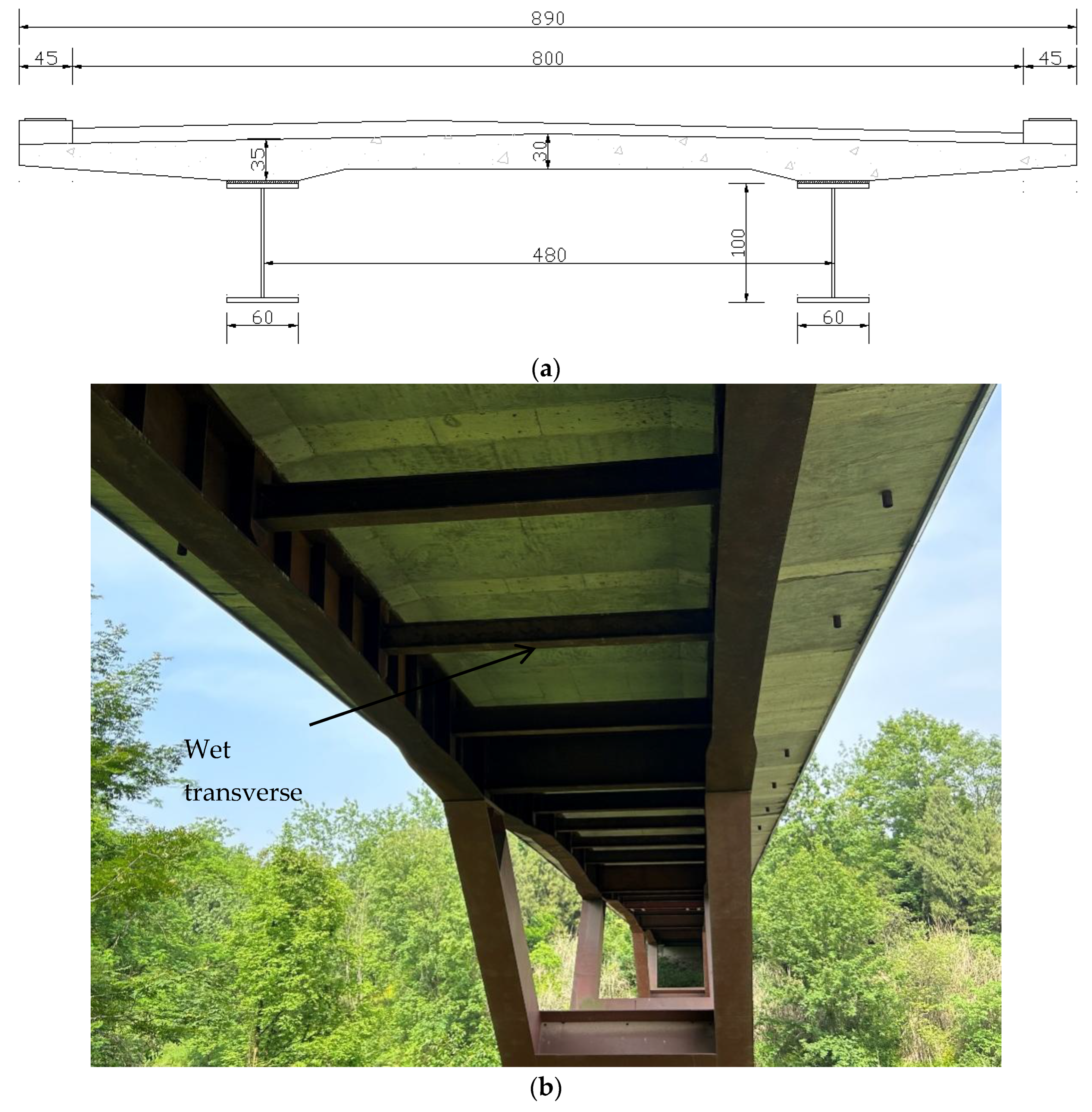
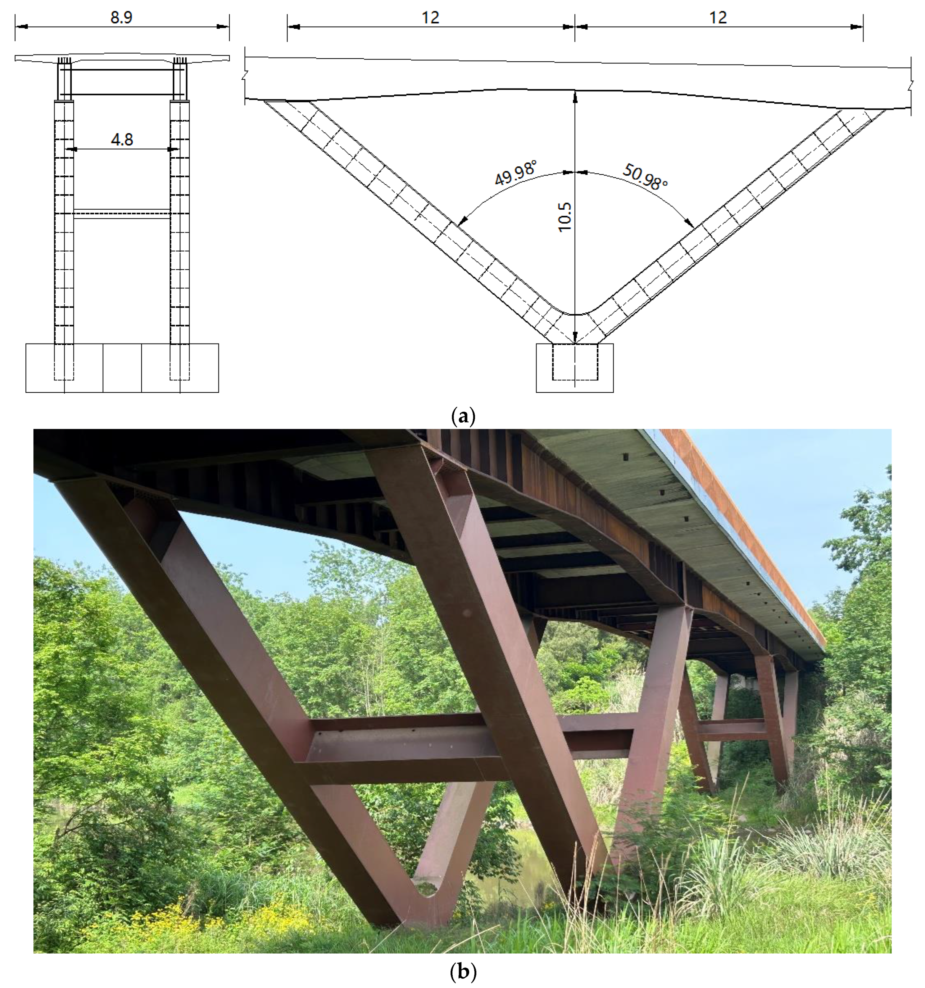
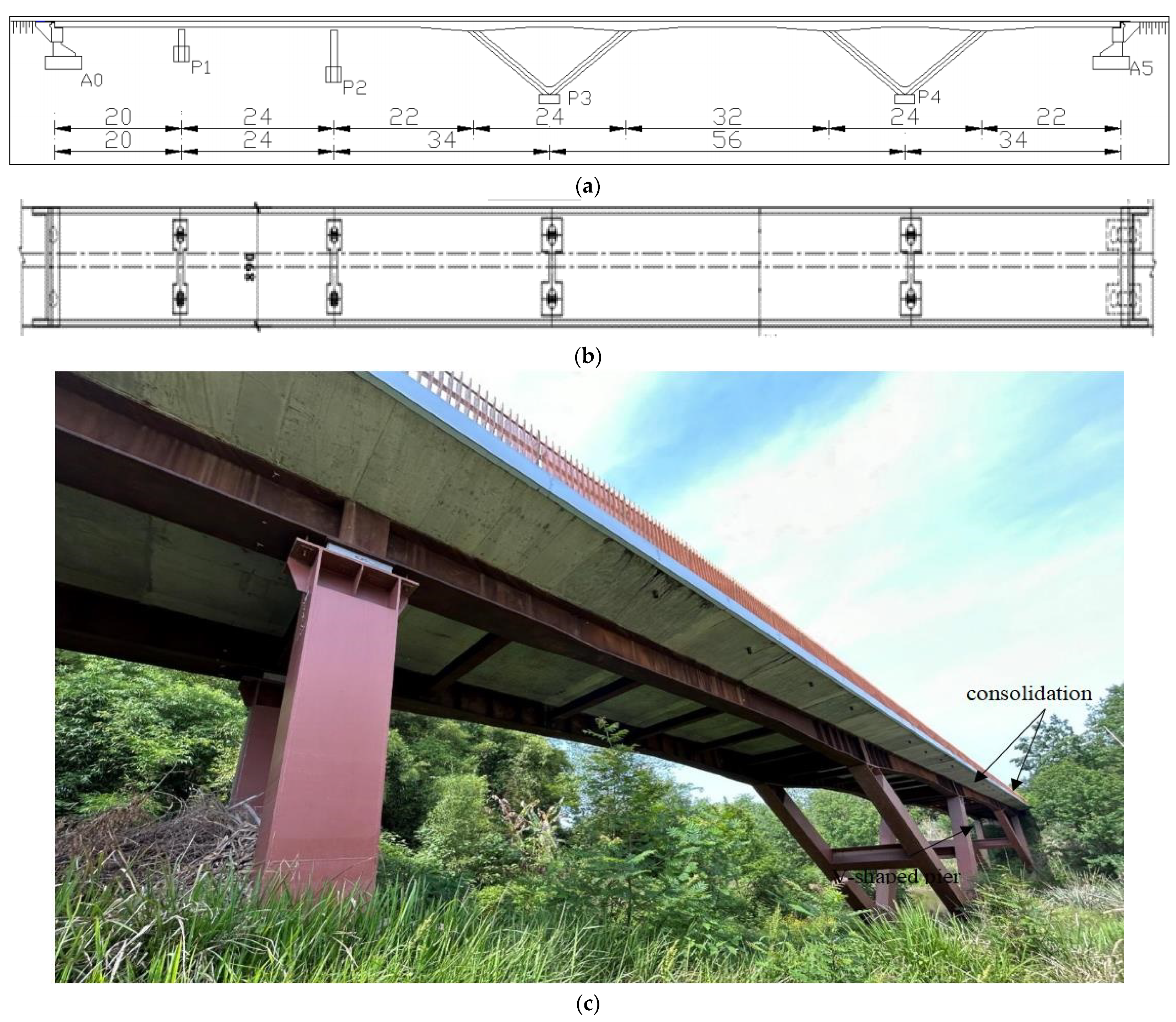
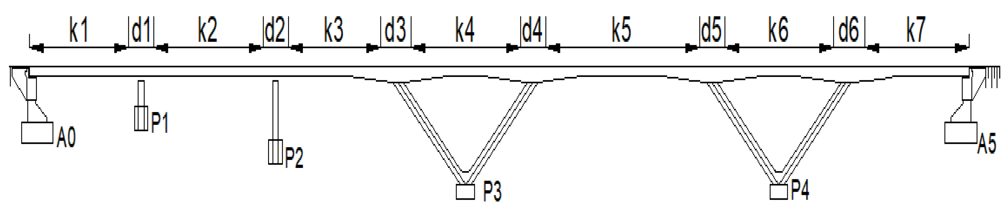
2. Engineering Background
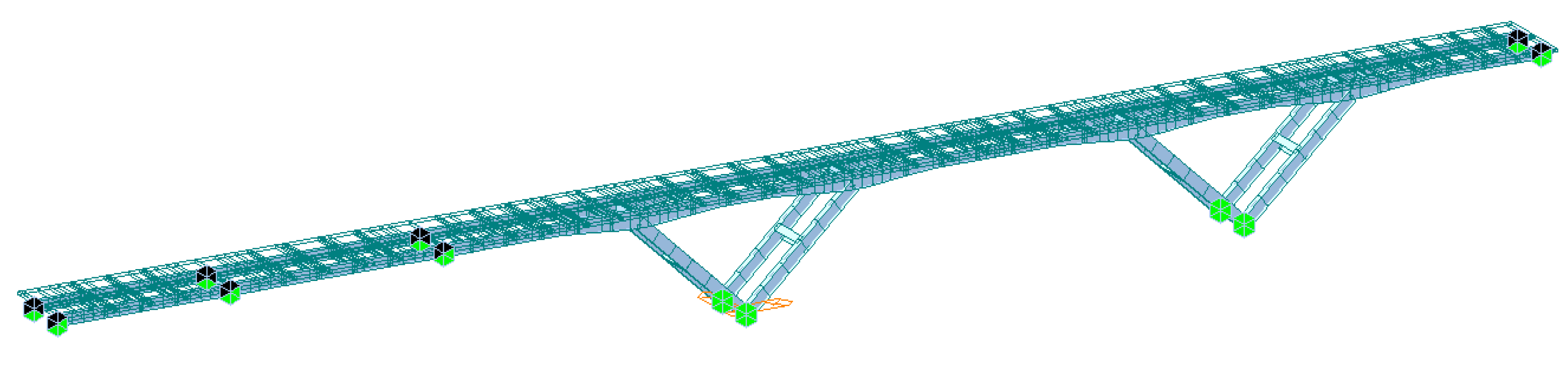
3. Finite Element Model
3.1. Division of Construction Stages
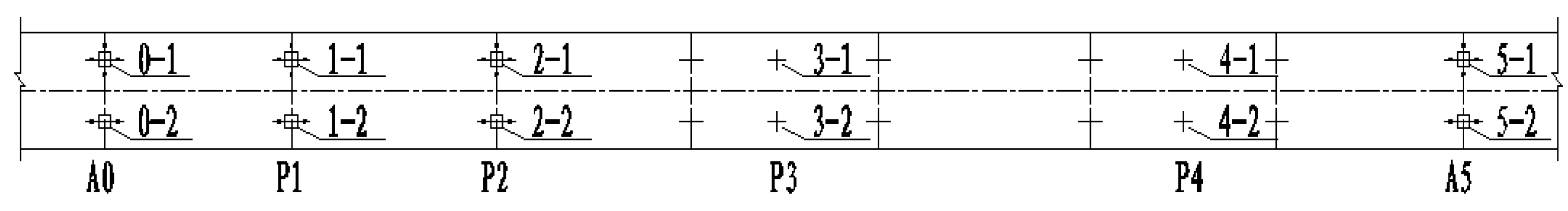
3.2. Parameter Selection
4. Calculation Results of the Phased Construction Process
4.1. Results of the Steel Beam Structure Construction Completion Stage (CS1)
4.2. Analysis of Precast Slab Pavement Completion Stage (CS2)
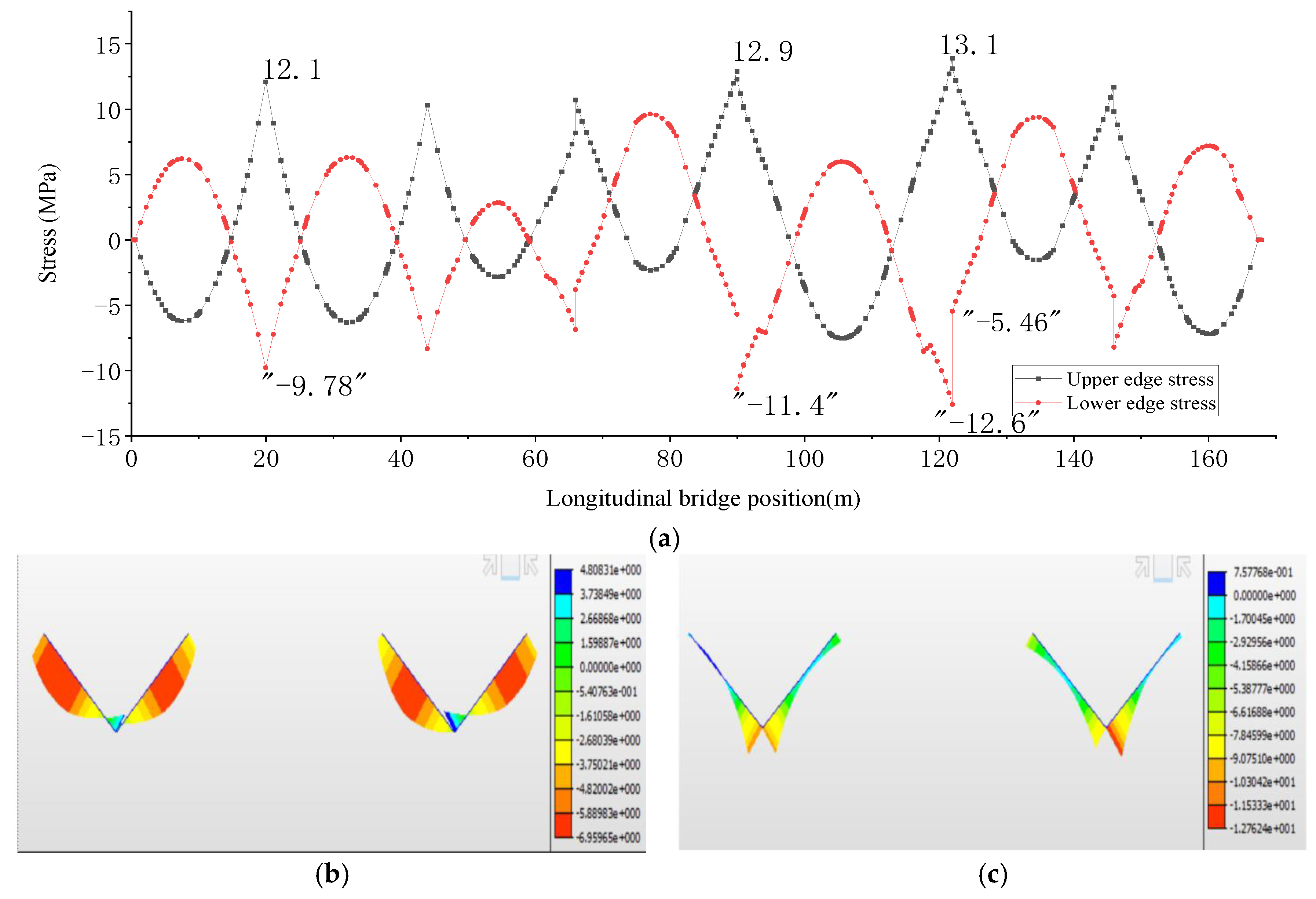
4.3. Analysis of the Bridge Completion Stage
4.4. Comparative Analysis of Each Stage
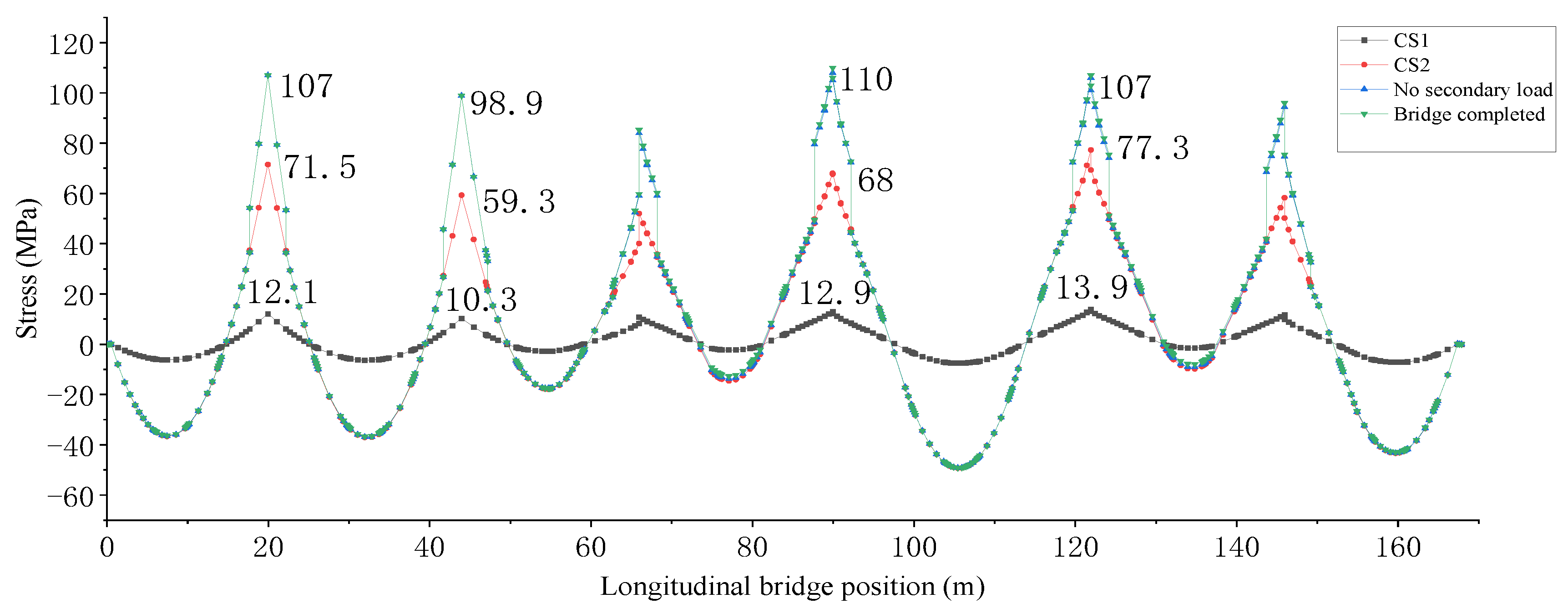
- (1)
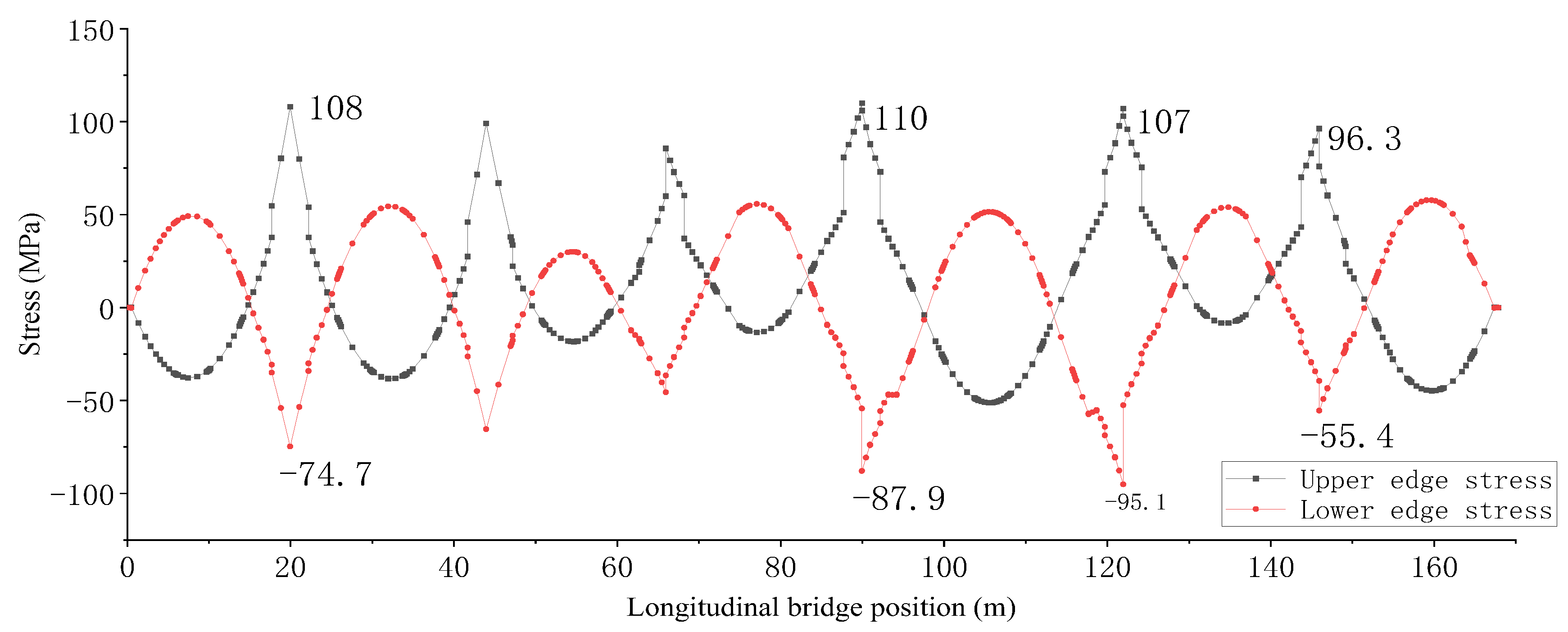
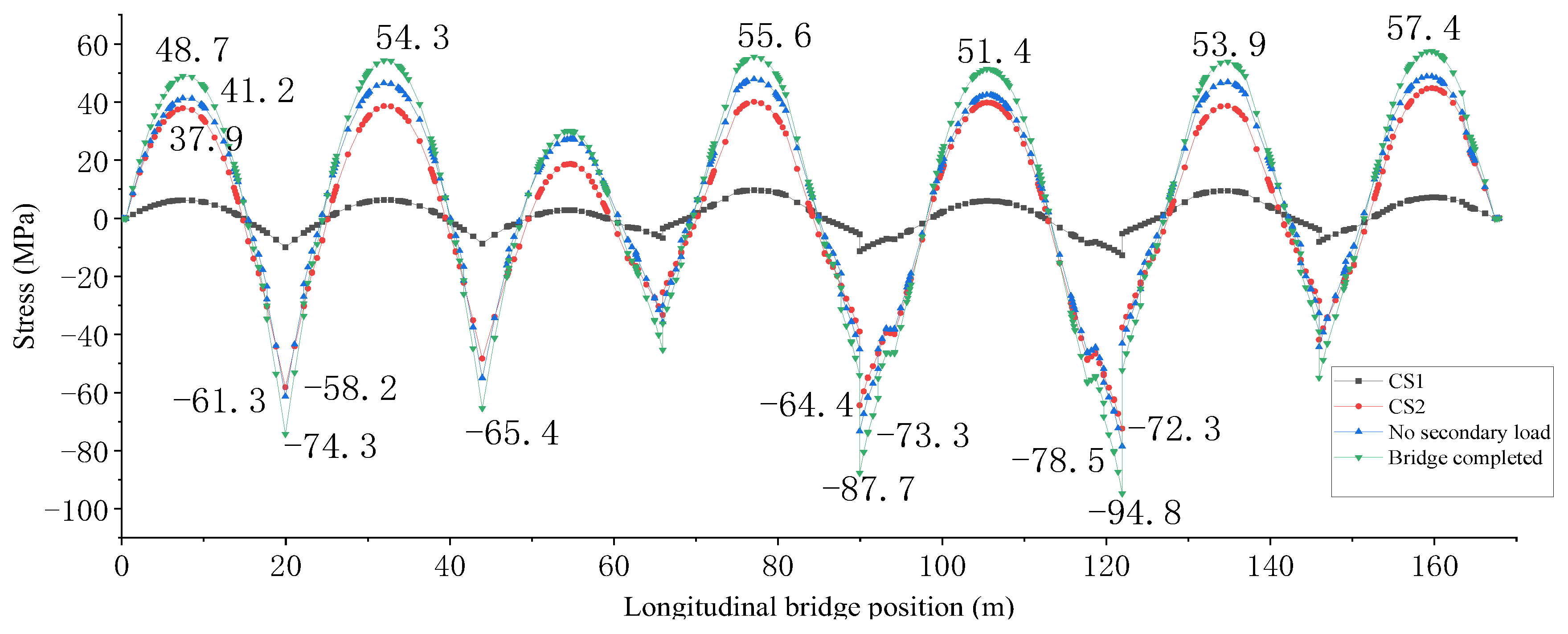
- Flange stress on the steel beam
- (2)
- Stress of lower flange of steel beam
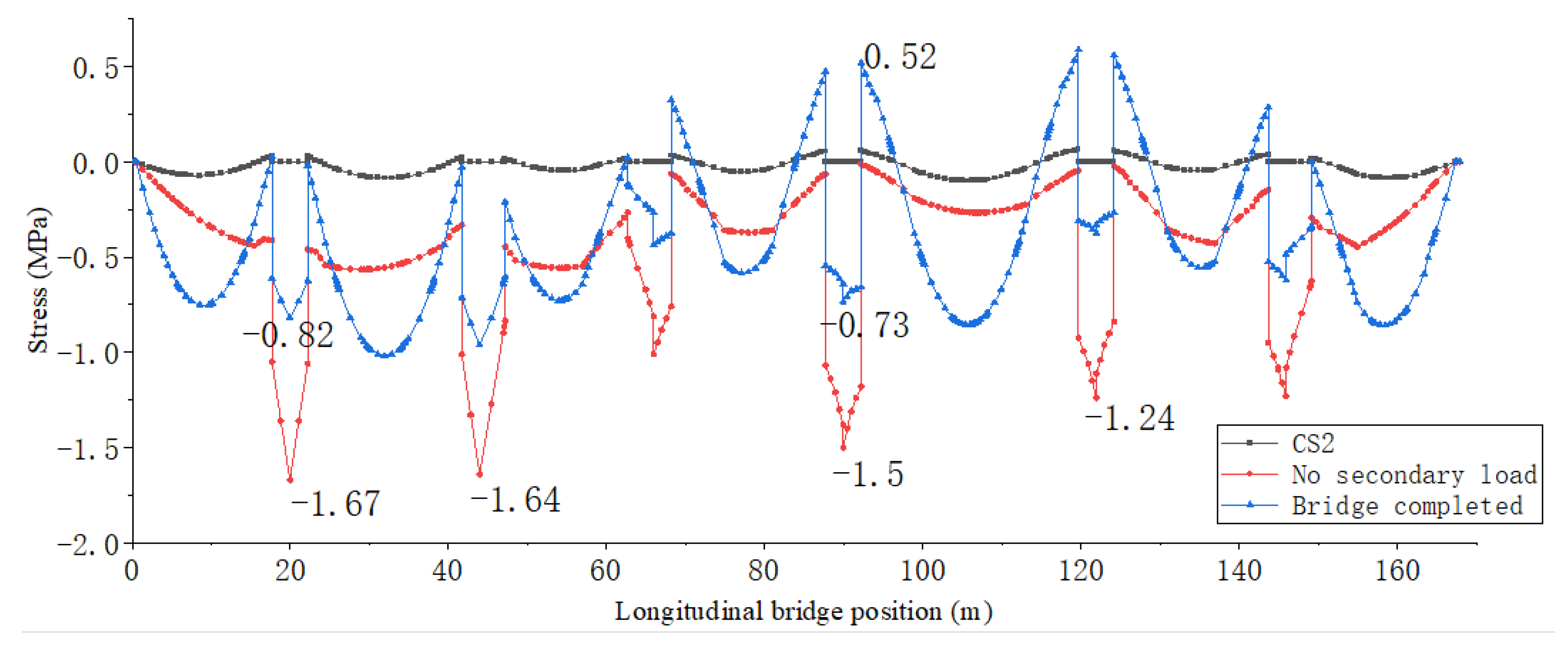
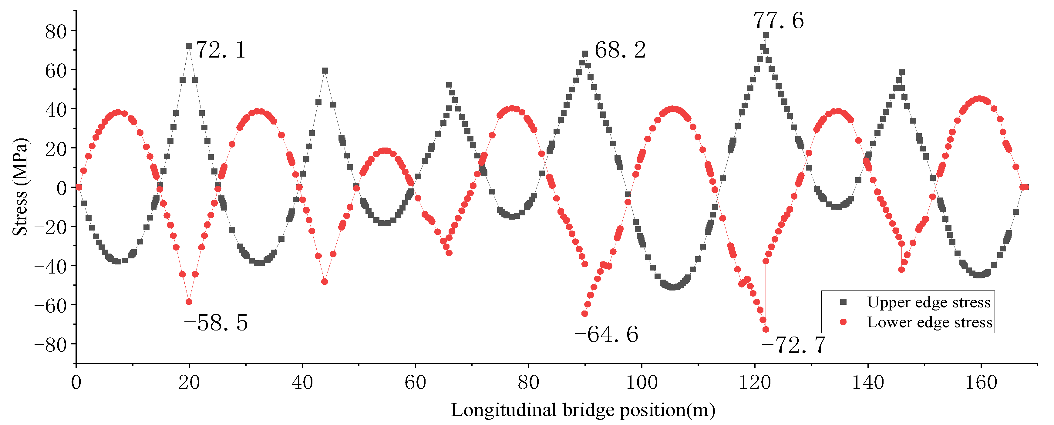
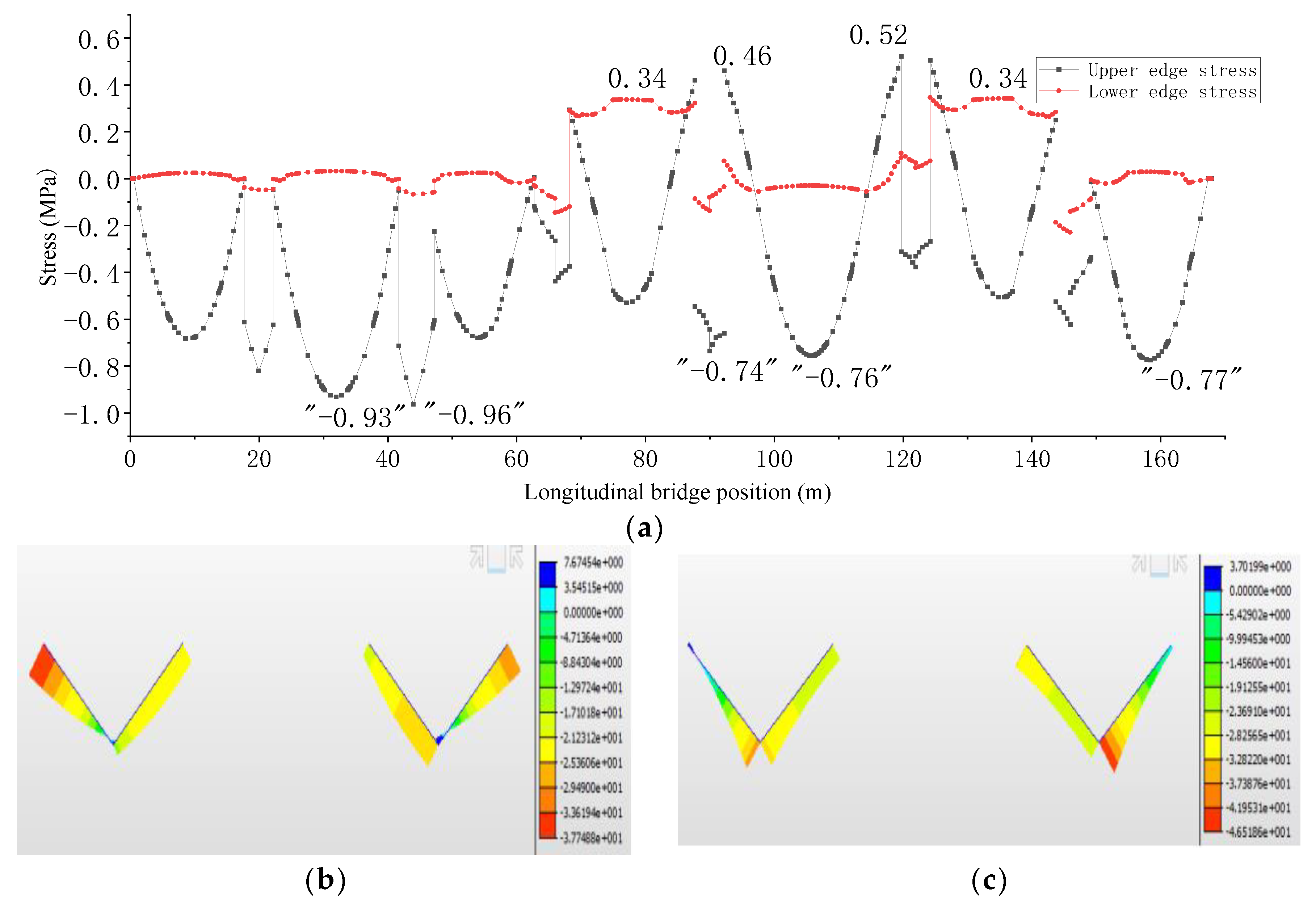
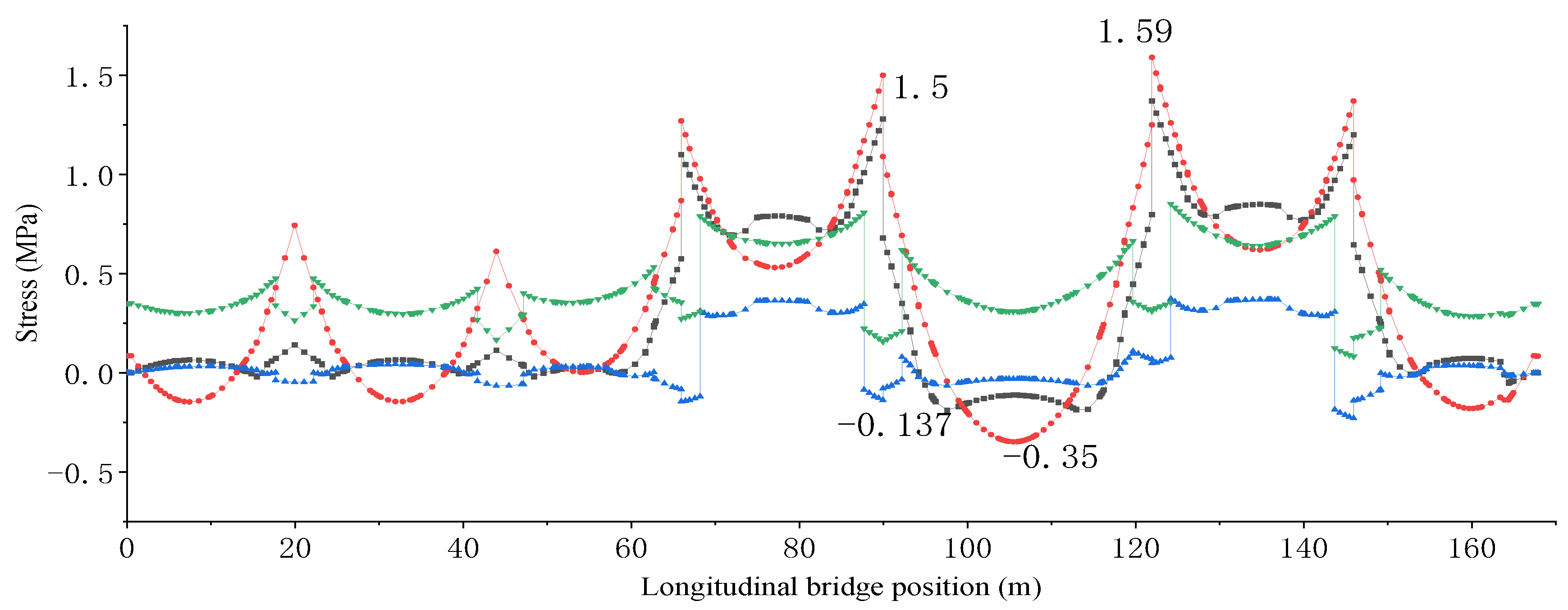
- (3)
- Stress of the upper edge of the concrete slab
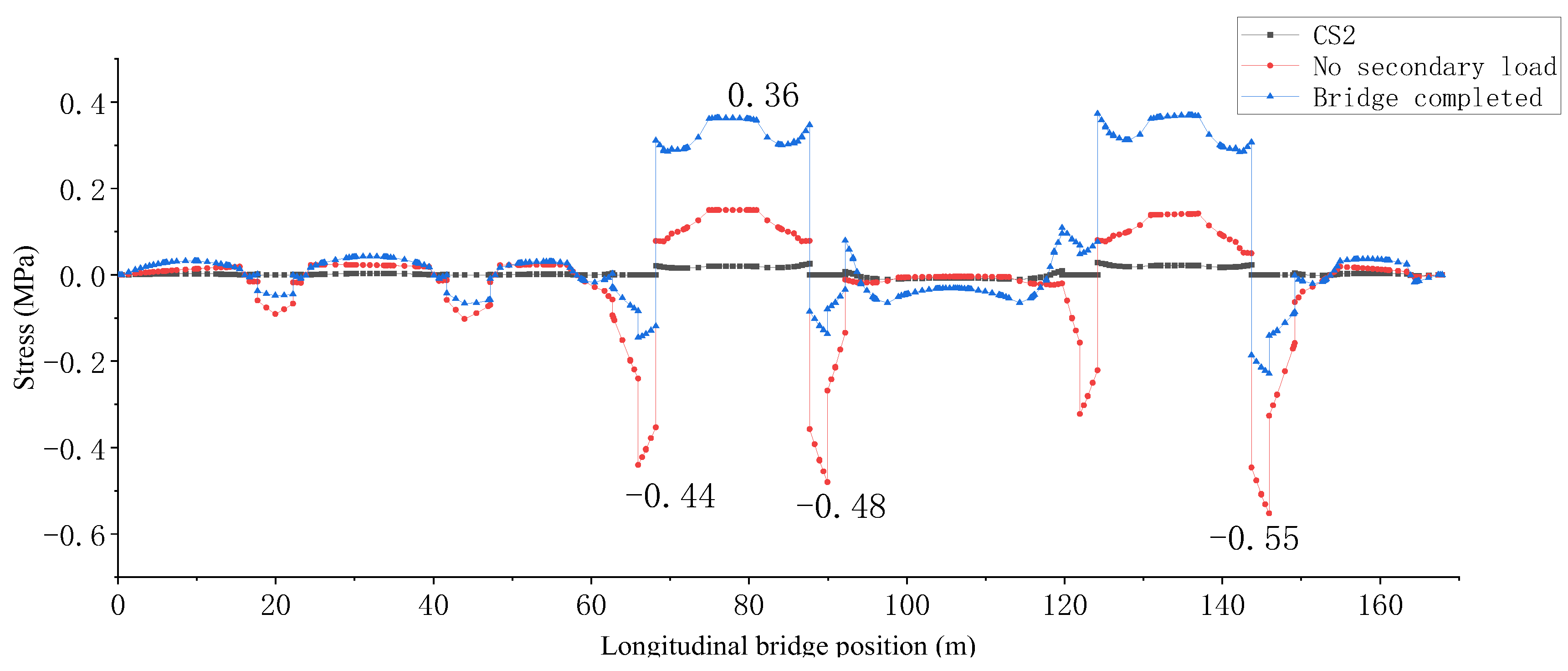
- (4)
- Stress of the lower edge of the concrete slab
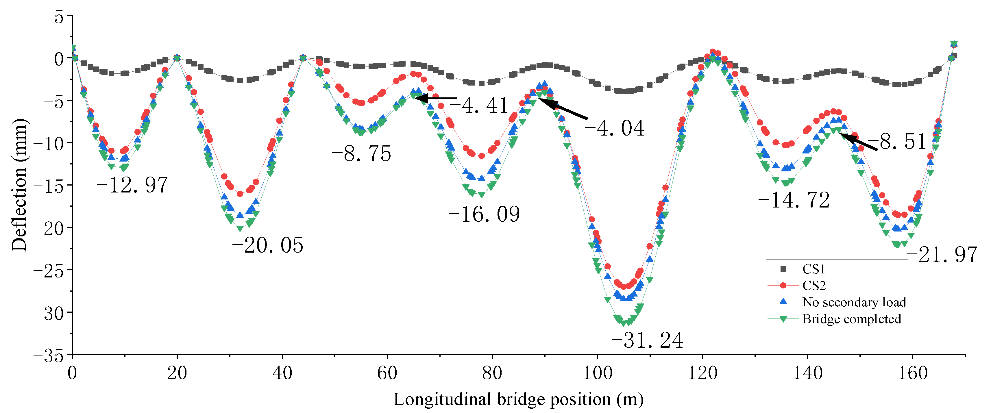
- (5)
- Deflection variation of the whole bridge during construction
5. Comparisons between One-Time and Staged Formation of Combined Sections
5.1. Deflection Difference in the Completed Bridge
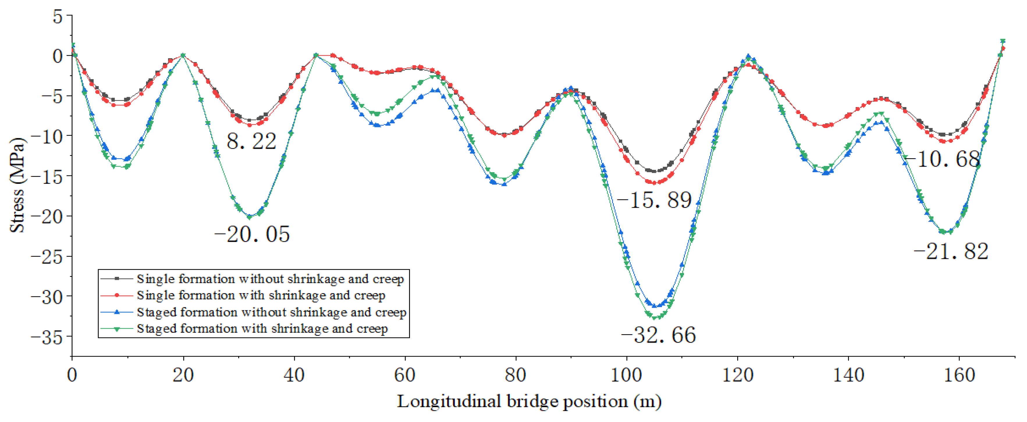
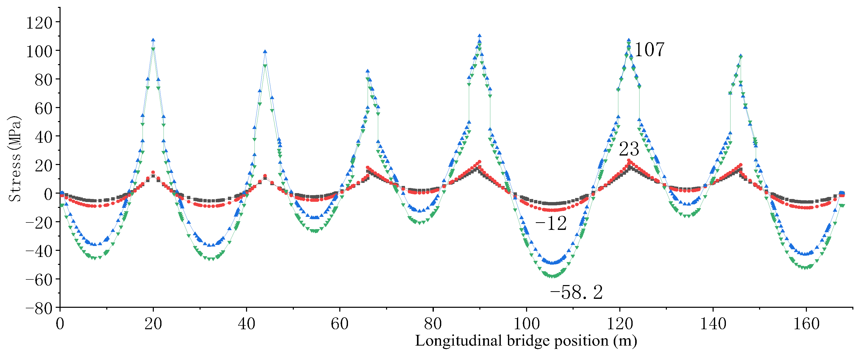
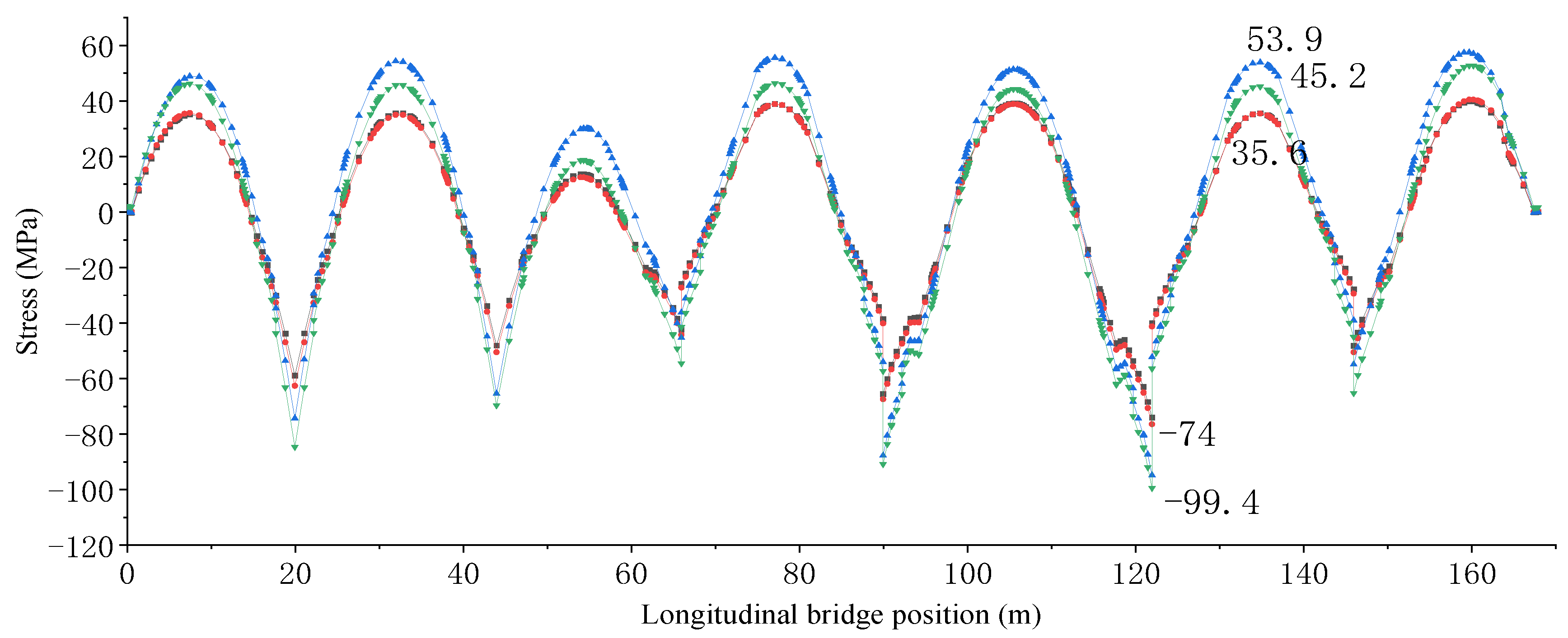
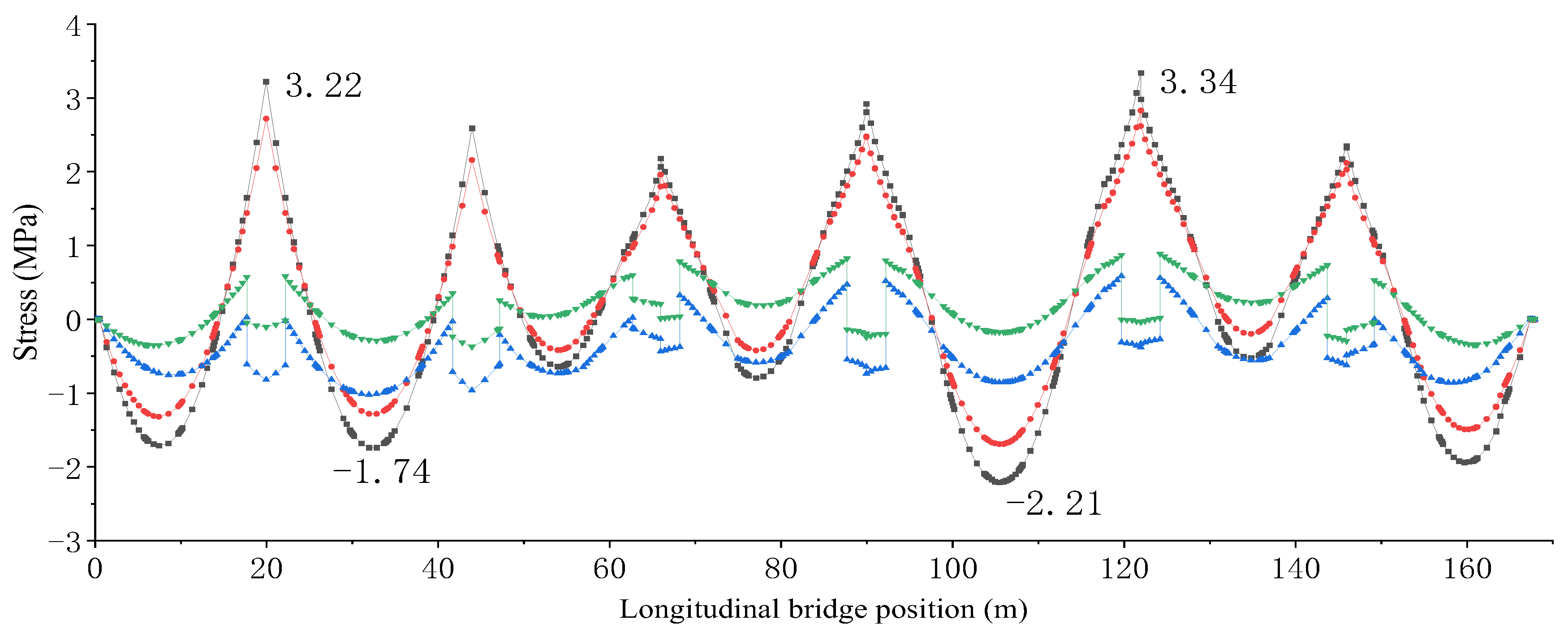
5.2. Stress Difference in the Completed Bridge
6. Conclusions
- (1)
- The stress of the upper flange of the steel beam in a cast-in-place section of the pier top is basically stable after the completion of cast-in-place concrete construction. Thereafter, the secondary load has no obvious effect on the stress of the upper flange of the steel beam. The substructure of the V-shaped pier results in additional tensile stress on the lower flange of the steel girder at the top of the V-shaped pier;
- (2)
- When the tensile stresses in the upper flange of the steel main girders at the top of the vertical and V-shaped piers are equal in magnitude, in the upper and lower edges of bridge slabs, the compressive stress reserve of the vertical pier is higher than that of the top cast-in-place section of V-shaped pier;
- (3)
- The bridge formation model without considering the construction process was compared with the finite element calculation results considering the construction process. The difference in stresses in the concrete slab between the two cases is found to be up to 2.7 MPa, indicating that the stress state in the bridge formation of the continuous beam and V-shaped pier rigid frame bridge with a steel–concrete composite girder is strongly influenced by the construction process;
- (4)
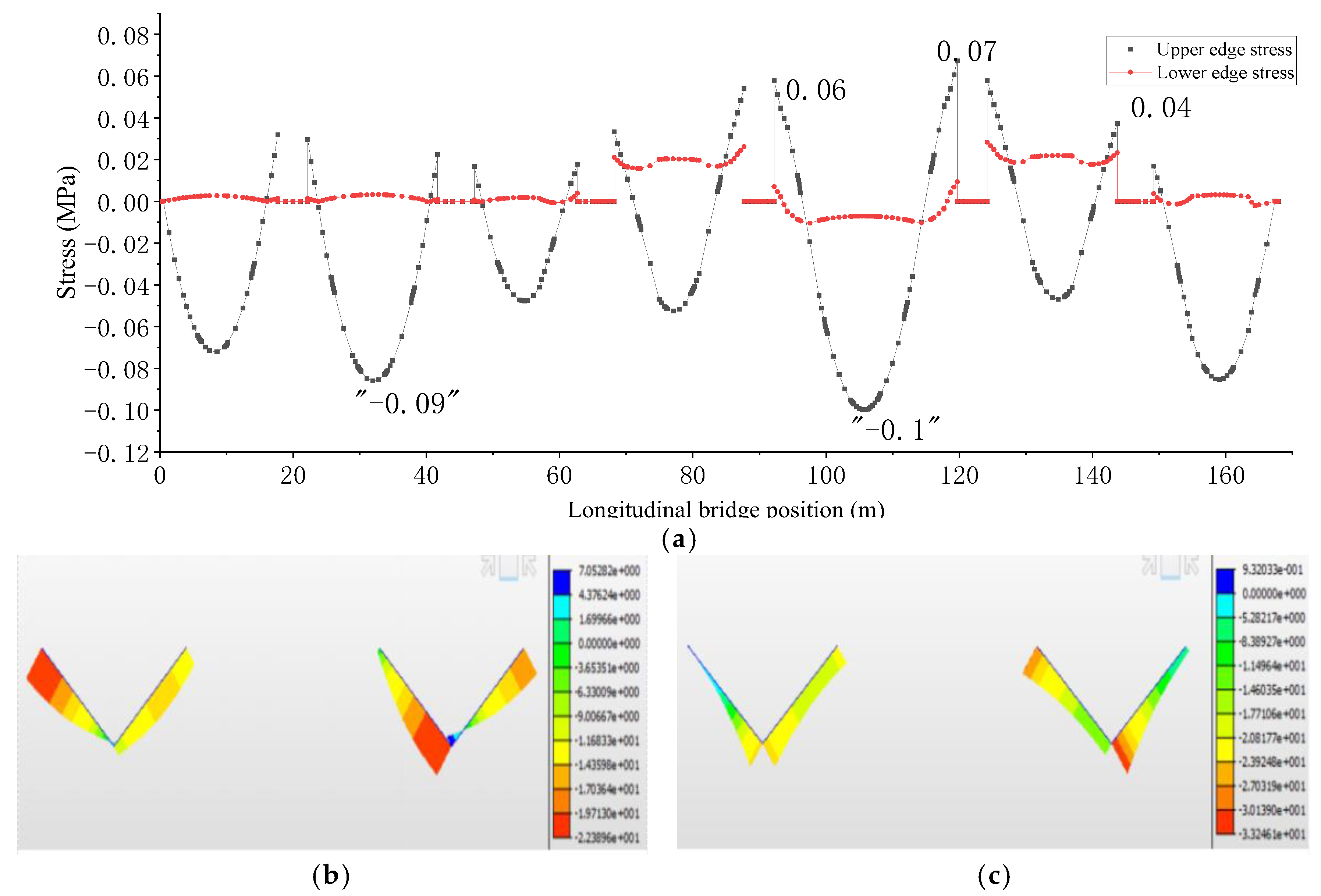
- There is a certain tensile stress on the upper edge of the concrete bridge floor in the negative bending moment area at the top of the V-shaped pier under the condition of bridge formation, up to 0.5 MPa, and the tensile stress may increase under the action of load, temperature difference, shrinkage, creep, etc., which is unfavorable to the stress of the concrete structure. During construction, prestressed steel bundles can be considered to make the fulcrum attachment bridge panel have a certain compressive stress when the bridge is formed.
Author Contributions
Funding
Institutional Review Board Statement
Informed Consent Statement
Data Availability Statement
Conflicts of Interest
References
- Llombart, J.A.; Revoltós, J.; Fernández, J. Teror viaduct in Gran Canaria Island, Spain. Struct. Eng. Int. J. Int. Assoc. Bridge Struct. Eng. (IABSE) 2014, 24, 111–113. [Google Scholar] [CrossRef]
- Manuilov, G.A.; Kositsyn, S.B.; Begichev, M.M. Changes in post critical equilibrium and localization effects of elastic elongated plates. IOP Conf. Ser. Mater. Sci. Eng. 2018, 456, 012078. [Google Scholar] [CrossRef]
- Liu, J.; Huang, S.; Li, J.; Chen, Y.F. Vibration Serviceability of Large-span Steel–Concrete Composite Beam with Precast Hollow Core Slabs under Walking Impact. Engineering 2022, 19, 93–104. [Google Scholar] [CrossRef]
- Hao, Y. Study on Spatial Stress Analysis and Parameter Optimization of Construction Stage of Large Span V Braced Continuous Girder Bridge for High-Speed Railroad. Master’s Thesis, Lanzhou Jiaotong University, Lanzhou, China, 2018. [Google Scholar]
- Zeng, Y.; Li, Y.; Yu, T.; Wei, J. Aalysis of Mechanical Performance of Steel-Concrete Composite Girder Bridge with V-Shaped Piers. Adv. Civ. Eng. 2022, 2022, 6489140. [Google Scholar]
- Liang, L.; Ming, Y.; Jian, W. Nonlinear Finite Element Analysis of Continuous Steel-Concrete Composite Beams. Appl. Mech. Mater. 2014, 3489, 638–640. [Google Scholar]
- Zhang, F.; Wang, Y. Spatial Stress of the Pier-Girder Rigid Region of a Continuous Rigid-Frame Bridge with V-Shaped Piers in Two Directions. J. Highw. Transp. Res. Dev. 2020, 14, 45–54. [Google Scholar] [CrossRef]
- Zheng, Y.; Cao, Z.; Guo, P.; Gao, P.; Zhang, P. Fatigue Performance of Steel-Concrete Composite Continuous Box Girder Bridge Deck. Complexity 2021, 2021, 6610830. [Google Scholar] [CrossRef]
- Shi, Z.; Sun, Z.; Yang, S.; Zhou, K. Fatigue Performance of Butt-Welded Tensile Plate Cable-Girder Anchorages of Long-Span Cable-Stayed Steel Box Girder Railway Bridges. J. Bridge Eng. 2021, 26, 04020108. [Google Scholar] [CrossRef]
- Yin, G.A.; Ding, F.X.; Wang, H.B.; Bai, Y.; Liu, X.M. Connection Performance in Steel–Concrete Composite Truss Bridge Structures. J. Bridge Eng. 2016, 22, 04016126. [Google Scholar] [CrossRef]
- Zhang, Z. Steel-Concrete Combination Structure Strengthening Method On Bridge Maintenance. IOP Conf. Ser. Earth Environ. Sci. 2019, 283, 012032. [Google Scholar] [CrossRef]
- Bilotta, A.; Morassi, A.; Turco, E. Damage identification for steel-concrete composite beams through convolutional neural networks. J. Vib. Control 2024, 30, 876–889. [Google Scholar] [CrossRef]
- Wang, S.; Fang, Z.; Chen, G.; Jiang, H.; Teng, S. Numerical Analysis on Shear Behavior of Grouped Head Stud Shear Connectors between Steel Girders and Precast Concrete Slabs with High-Strength Concrete-Filled Shear Pockets. J. Bridge Eng. 2022, 26, 04021030. [Google Scholar] [CrossRef]
- Wu, C.; Yu, Q.; Zhu, B.; Ling, H.; Zheng, J.; He, S. Test Research on Toughness Evaluation of Long-span Bridge Welded Joint. IOP Conf. Ser. Earth Environ. Sci. 2021, 787, 012192. [Google Scholar] [CrossRef]


| Construction Stage | Construction Contents |
|---|---|
| CS1 | Construction of substructures and steel beams |
| CS2 | Installation of precast bridge decks from k1 to k7 and pouring of wet joints |
| CS3 | Preloading the mid-span of k1 and k2 beam sections and cast-in-place d1 beam section concrete |
| CS4 | Unloading the preload of k1, preloading the mid-span of k2 and k3 then cast the concrete of d2 beam section in situ |
| CS5 | Unloading the preload of k2, preloading the mid-span of k3 and k4 then cast the concrete of d3 beam section in situ |
| CS6 | Unloading the preload of k3, preloading the mid-span of k4 and k5 then cast the concrete of d4 beam section in situ |
| CS7 | Unloading the preload of k4, preloading the mid-span of k5 and k6 then cast the concrete of d5 beam section in situ |
| CS8 | Unloading the preload of k5, preloading the mid-span of k6 and k7 then cast the concrete of d6 beam section in situ |
| CS9 | Unloading the preload of k6 and k7 preloading and applying secondary loads |
Disclaimer/Publisher’s Note: The statements, opinions and data contained in all publications are solely those of the individual author(s) and contributor(s) and not of MDPI and/or the editor(s). MDPI and/or the editor(s) disclaim responsibility for any injury to people or property resulting from any ideas, methods, instructions or products referred to in the content. |
© 2024 by the authors. Licensee MDPI, Basel, Switzerland. This article is an open access article distributed under the terms and conditions of the Creative Commons Attribution (CC BY) license (https://creativecommons.org/licenses/by/4.0/).
Share and Cite
Zeng, Y.; Yu, T.; Xiao, Y.; Li, W. Investigation of the Mechanical Features of Steel–Concrete Composite Girder Rigid Frame Bridges with V-Shaped Piers during Construction Stages. Appl. Sci. 2024, 14, 3343. https://doi.org/10.3390/app14083343
Zeng Y, Yu T, Xiao Y, Li W. Investigation of the Mechanical Features of Steel–Concrete Composite Girder Rigid Frame Bridges with V-Shaped Piers during Construction Stages. Applied Sciences. 2024; 14(8):3343. https://doi.org/10.3390/app14083343
Chicago/Turabian StyleZeng, Yong, Tao Yu, Yunchuan Xiao, and Weilong Li. 2024. "Investigation of the Mechanical Features of Steel–Concrete Composite Girder Rigid Frame Bridges with V-Shaped Piers during Construction Stages" Applied Sciences 14, no. 8: 3343. https://doi.org/10.3390/app14083343