1. Introduction
China is rich in coal resources, and coal, as the main energy source in our country, plays an important role in economic development. With the increasing level of mine intelligence, mechanization, and automation, the potential hazards of gas, coal dust, fire, and other disasters have increased. Especially concerning is the issue of dust pollution in mines, which leads to the deterioration of underground air quality and causes workers to suffer from pneumoconiosis. Additionally, dust accumulation can easily lead to explosion accidents, severely impacting enterprise safety. Furthermore, it poses a significant threat to the occupational health of workers [
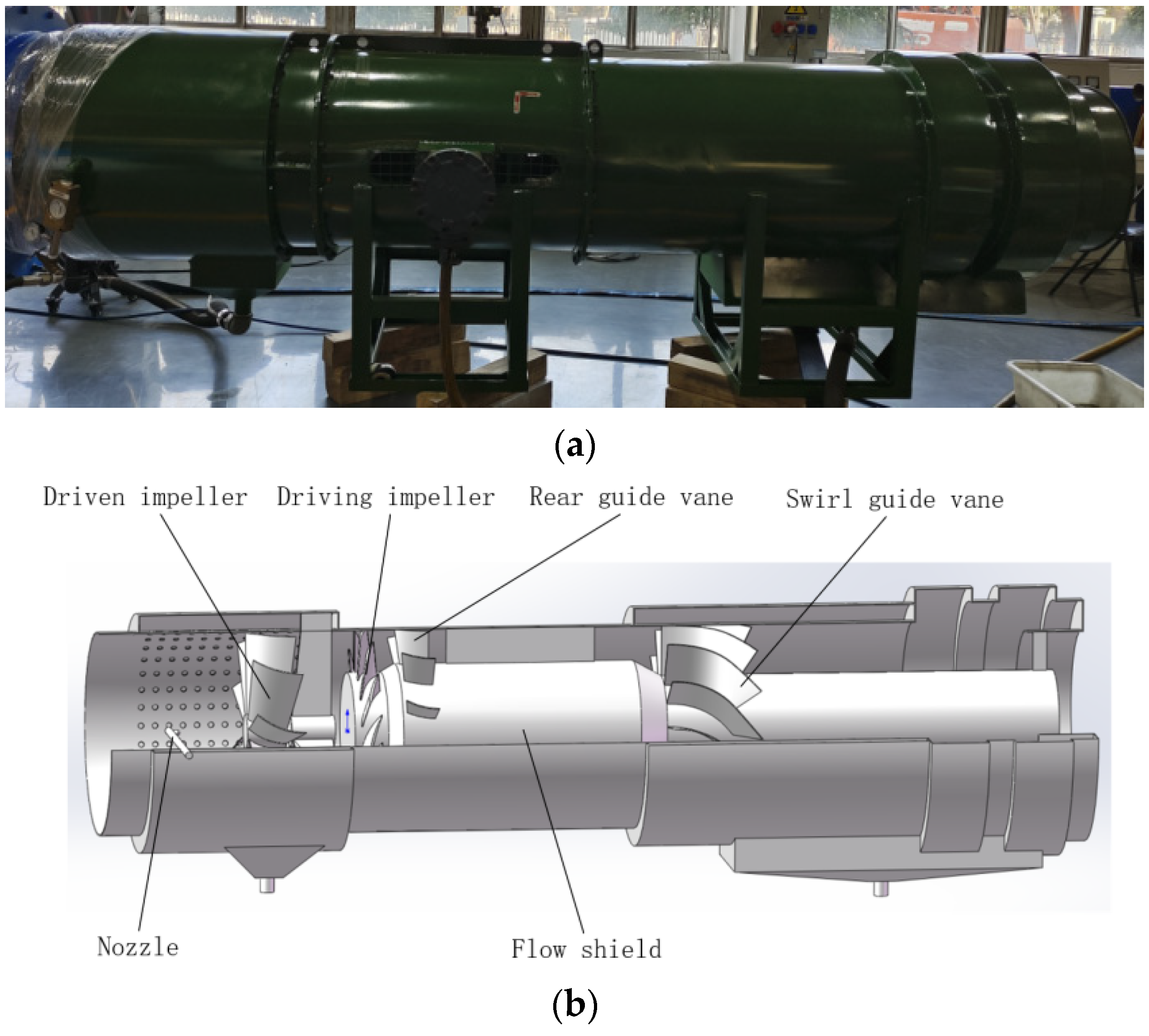
1]. A fan is an essential key component in the underground dust removal system. However, traditional fans only provide power for the airflow in the dust removal system and do not directly participate in dust removal. On the other hand, wet dust removal fans are equipped with spray dust removal devices, enabling them to directly remove dust inside the fan, thus significantly enhancing dust removal efficiency [
2,
3,
4]. The main components of wet dust removal fans include driving impellers, driven impellers, rear guide vanes, swirl guide vanes, etc., whose structural parameters greatly affect dust removal performance [
5].
Many scholars have studied the influence of structural parameters of axial flow fans and dust removal fans on aerodynamic performance through fluid simulation software. Huang Ceng’an [
6] conducted simulation tests using FLUENT software by altering key structural parameters of axial flow in rotary dust removal fans and investigated their impact on working performance. Zhang Lixiang et al. [
7,
8] analyzed the influence of structural parameters such as impeller hub ratio, blade number, blade installation angle, blade chord length, blade twist angle, and impeller radial clearance on the performance of the mining KJS-Y dust removal fan using FLUENT software. Zhao Zhongtai [
9] utilized CFX software to calculate the aerodynamic performance parameters of the rotor blade of the dust removal fan at different installation angles. Ye Xuemin et al. [
10] employed the large eddy simulation method to numerically simulate a two-stage variable pitch axial flow fan with zigzagged flaps and studied the influence of the new blade on the aerodynamic performance, noise characteristics, and internal dynamics characteristics of the fan. Gao Guijun et al. [
11] focused on the FBD No.8.0 mine counterrotating fan and studied the effect of blade angle on fan performance through orthogonal tests and numerical simulations. Tian Chenye et al. [
12] used numerical simulation to investigate the influence of bionic butterfly blades with different depression depths on the aerodynamic performance of air conditioning axial fans. In the aforementioned research, the total pressure, static pressure, and total pressure efficiency of the dust removal fan are considered as evaluation indexes of dust removal performance, but the dust removal efficiency is not numerically simulated.
Concurrently, scholars have explored the factors affecting the performance of the dust removal fan through experimental methods. Hu Fei et al. [
13] analyzed the working principle of the wet cyclone dust extractor and the dust removal process of new impellers, cyclone blades, and other structures. Hu Shengyong et al. [
14,
15,
16] conducted dust removal and dewatering performance tests of a wet scroll dust collector using a dust collector purification performance test platform and studied the dewatering effect of the dust collector under different water consumption rates and the dust removal effect at different concentrations. Jin Zijing et al. [
17] investigated the influence of water intake and impeller speed on the dust removal efficiency of a wet cyclone dust collector through experiments. Zhu Nengtian et al. [
18] established an experimental device to study the influence of factors such as the thickness of porous media, liquid–gas ratio, and water level height on the performance of porous media wet dust collectors in collecting fine particles. The above research examines the dust removal principle of the internal structure of the dust removal fan and analyzes the influence of factors such as impeller speed and water intake on dust removal efficiency through experiments but does not modify the structure of the dust removal fan to investigate dust removal performance under different structural parameters.
Many scholars have utilized the discrete phase model to simulate the dust removal process inside dust removal fans [
19,
20]. Zhao Haiming et al. [
21,
22] employed FLUENT software to simulate the three-phase flow field of wet dust removal fans and analyzed the effects of dust particle size, liquid–gas ratio, fan speed, and other operating parameters on the dust removal efficiency of wet dust removal fans. Li Huijun et al. [
23] used the FLUENT discrete phase model to simulate and study the motion trajectory and deposition characteristics of oily particles in a multi-wing centrifugal fan, exploring the influence of particle diameter on deposition distribution. Wu Zhuang et al. [
24] simulated and analyzed the flow field, pressure, and dust removal efficiency of cyclone dust collectors based on the discrete phase model. Wang Yunlong et al. [
25] employed FLUENT software to conduct gas–liquid–solid three-phase numerical simulations of the internal flow field of downhole wet precipitators and analyzed the distribution of the internal flow field. Tang Puhua et al. [
26] utilized CFD software to simulate particle trajectories in the solid-phase flow field inside radial straight blade wet cyclone dust collectors, obtaining the relationship between particles with different sizes and separation efficiency under different inlet wind speeds. Zhong Yang et al. [
27] used FLUENT 14.0 software to numerically simulate the three-phase coupled flow field under the working state of wet swirl dust removal fans for mining and analyzed the influence of factors such as driven impeller speed and particle size distribution on dust removal efficiency. The aforementioned research numerically simulates the dust removal efficiency of dust removal fans through the discrete phase model; however, the exploration of dust removal efficiency under different structural parameters remains insufficiently deep.
It can be observed from the above references that there are currently two main research methods for dust removal fans: physical testing and numerical simulation. Among these, physical testing is highly reliable, but it is often challenging to study and analyze due to the requirement of setting multiple sets of dust removal fan structural parameters. Numerical simulation of dust removal fans encompasses two approaches: altering the structural parameters to simulate the fan’s aerodynamic performance and using the discrete phase model to simulate dust removal efficiency. Present research tends to concentrate on one of these methods. In this paper, the Computational Fluid Dynamics (CFD) method is employed to numerically simulate and analyze the influence of the driving impeller, driven impeller, rear guide vane, swirl guide vane, and outlet section on the dust removal performance of wet dust removal fans for mining. By modifying the number of driving impeller blades, the airfoil of driving impeller blades, the number of driven impeller blades, presence or absence of rear guide blades and swirl guide blades, and the length of the outlet section, different dust removal fan impeller models were established and numerically simulated. The influence of structural parameters on the dust removal performance of wet dust removal fans for mining was analyzed through indicators such as total pressure efficiency, static pressure efficiency, and dust removal efficiency. This provides a valuable reference for subsequent related research and practical engineering applications.
3. Numerical Simulation Scheme of Dust Removal Fan
3.1. Solve the Settings and Boundary Conditions
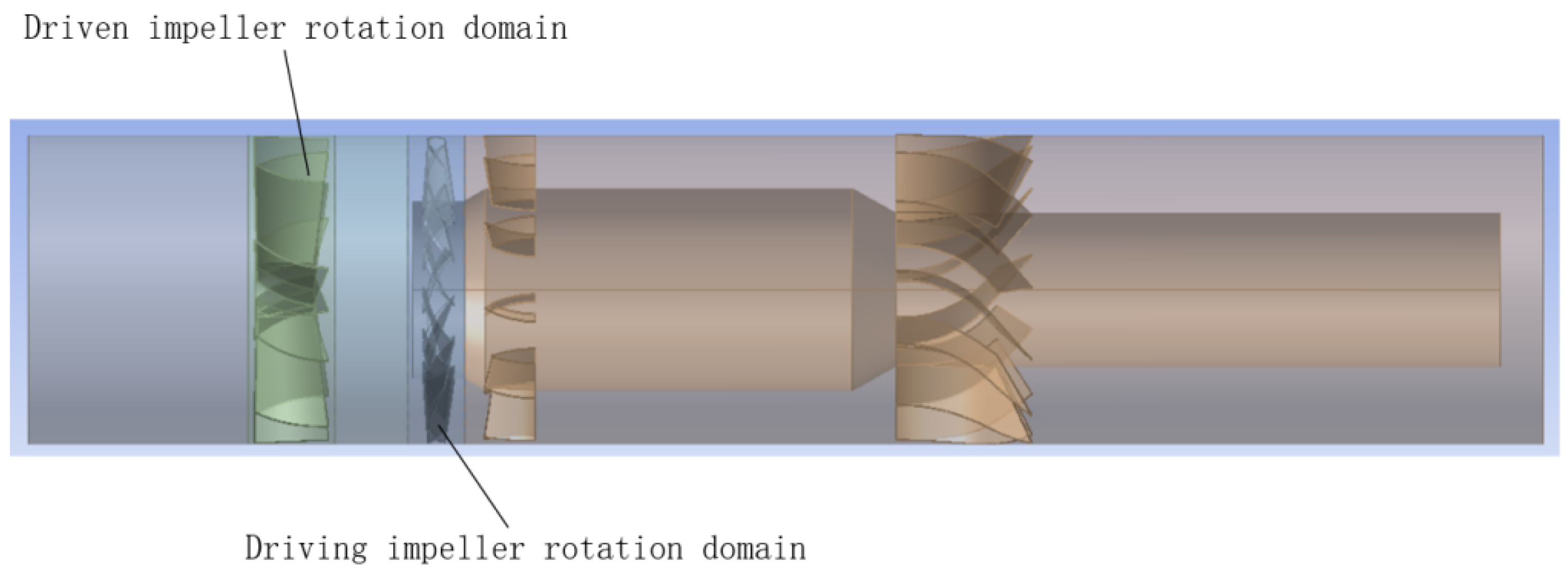
In this paper, the CFD method is used for numerical simulation analysis of the internal flow field of the dust removal fan. The numerical simulation settings are as follows: As the process of rotation of the driven impeller driven by the airflow needs to be simulated, the model adopts transient calculation. The driven impeller rotation domain adopts the dynamic grid model; the mass of the driven impeller, the center of gravity coordinate, and the moment of inertia around the Z axis are set in the options of 6DOF. Due to the use of transient simulation, the sliding grid model was used in the rotation domain of the driving impeller, and the speed was set to 2900 rpm. The continuous phase adopts air with a density of 1.225 kg/m3 and a viscosity of 1.7894 × 10⁻5 N·s/m2. The inlet of the fluid domain is set as the velocity inlet. Because the design air volume of the dust removal fan is 400 m3/min, and the measured value is 396.309 m3/min, the inlet speed is set to 16.405 m/s, converted from the circular inlet diameter of 716 mm. The outlet of the fluid domain adopts the pressure outlet, and the outlet pressure is set to 0 Pa. The interface between the rotation area of the driving impeller and the driven impeller, and other flow areas, is set as interface. The no-slip boundary condition is adopted on the solid wall. In the solution control, the coupling of pressure and velocity adopts the Simple algorithm, and the discrete scheme adopts second-order upwind. Because the Realizable k-ε model has good performance for rotating flow, boundary layer flow with strong inverse pressure gradient, shear flow, free flow, flow separation, and secondary flow, the internal structure and flow field of the wet dust removal fan studied in this paper are relatively complex. Therefore, the Realizable k-ε model is selected to deal with the continuous flow of the gas phase. In the simulation process, the convergence of the calculation is judged by monitoring the mean value of the total pressure of the outlet plane, the mean value of the outlet plane velocity, the mean value of the tangential velocity of the driven impeller, and the torque of the driven impeller.
The discrete phase model (DPM) is only applicable when the particle phase volume fraction is less than 10%. In this paper, the total particle flow rate is set to 0.001 kg/s, the incident velocity is set to 3 m/s, and the incident plane is the circular entrance of the dust removal fan with a radius of 0.358 m. Thus, the theoretical dust concentration at the inlet of the dust removal fan should be 8.279 × 10⁻⁴ kg/m3, while the particle density is 1550 kg/m3. Therefore, the volume fraction of the discrete phase is much lower than 10%, allowing for the utilization of the DPM model. Once the flow field inside the dust removal fan converges, the dust particle parameters are set in the discrete phase model and the dust removal performance of the fan is numerically simulated. Considering the complexity of the dust removal process of the dust removal fan, the simulation is simplified as follows: it is assumed that the droplets from the nozzle have formed a layer of water film on the inner wall of the dust removal fan and the dust particles are captured when they collide with the side wall of the dust removal fan. Furthermore, it is assumed that the particle size of the dust particles is 10 μm. The discrete phase parameters are set as follows: the surface was selected as the incident mode of the discrete phase, the incident location was chosen as the entrance plane of the dust removal fan, and the discrete phase material was designated as anthracite with a density of 1550 kg/m3. The particle size of the discrete phase was set at 10 μm, the incident velocity was set at 3 m/s, and the total flow rate was set at 0.001 kg/s. The side wall surface of the fluid domain is set to trap, the inlet and outlet plane of the dust removal fan are set to escape, and the other wall surfaces are set to reflect. Convergence is judged by monitoring the average discrete phase concentration of the outlet plane of the dust removal fan. Finally, the dust removal efficiency is calculated based on the simulation of the average discrete phase concentration of the outlet plane of the dust removal fan.
3.2. Governing Equation
CFD software requires the solution of the mass conservation equation and the momentum conservation equation for all flow problems. The mass conservation equation, also known as the continuity equation, is expressed as follows:
where
ρ represents density,
t represents time, and
v represents the velocity vector.
The momentum conservation equation in the inertial reference frame, also known as the equation of motion, is expressed as
where
p represents the pressure on the microfluid;
τij represents the component of viscous stress; and
Fx,
Fy, and
Fz represent the volume force component per unit of fluid.
The turbulence model in this paper adopts the Realizable K-ε model, and the model transport equations of turbulent kinetic energy k and dissipation rate ε are as follows:
and
where
Gk represents the turbulent kinetic energy generated by the average velocity gradient.
Gb represents the turbulent kinetic energy caused by buoyancy.
YM represents the effect of pulsating expansion on the total dissipation rate in compressible turbulence.
C1ε,
C3ε, and
C2 are empirical constants. The default values are
C1ε = 1.44,
C2ε = 1.92,
C3ε = 0.09, and
C2 = 1.9.
σk and
σε represent the Prandtl number corresponding to the turbulent kinetic energy and the turbulent dissipation rate respectively, and the default values are
σk = 1.0 and
σε = 1.2.
The discrete phase model predicts the motion trajectory of discrete phase particles by integrating the force balance on the particles in the Lagrange reference frame. Its particle motion equation is expressed as follows:
where
mp represents the mass of the particle,
U represents the velocity of the fluid phase,
Up represents the velocity of the particle,
ρ represents fluid density;
ρp represents particle density,
F stands for additional force, and
τr represents the relaxation time of the droplet or particle.
where
Cd represents the resistance coefficient of the sphere,
μ represents the molecular viscosity of the fluid,
dp represents the particle size, and
Re represents the relative Reynolds number.
3.3. Performance Evaluation Index of Dust Removal Fan
The performance evaluation index of a dust removal fan mainly includes total pressure efficiency, static pressure efficiency, and dust removal efficiency. The calculation methods for total pressure, static pressure, driving impeller shaft power, total pressure efficiency, static pressure efficiency, and dust removal efficiency are as follows:
Total pressure of fan:
where Δ
p represents total pressure of the fan, Pa;
p1 represents fan inlet total pressure, Pa; and
p2 represents fan outlet total pressure, Pa.
Static pressure of fan:
where Δ
pst represents static pressure of the fan, Pa;
pd2 represents fan outlet dynamic pressure, Pa.
Shaft power of the fan:
where
P represents the shaft power of the fan, kW;
T represents impeller torque, N·m; and
n represents impeller speed, r/min.
Total pressure effective power of fan:
where
Pe represents the total pressure effective power of the fan, kW;
qv represents fan flow, m
3/s.
The total pressure efficiency of the fan:
where
η represents the total pressure efficiency of the fan.
Static pressure effective power of the fan:
where
Pest represents the static pressure effective power of the fan, kW.
Static pressure efficiency of fan:
where
ηst represents the static pressure efficiency of the fan.
Dust removal efficiency of fan:
where
ηc represents the dust removal efficiency of the fan,
c1 represents discrete phase content at fan inlet, and
c2 represents discrete phase content at the fan outlet.
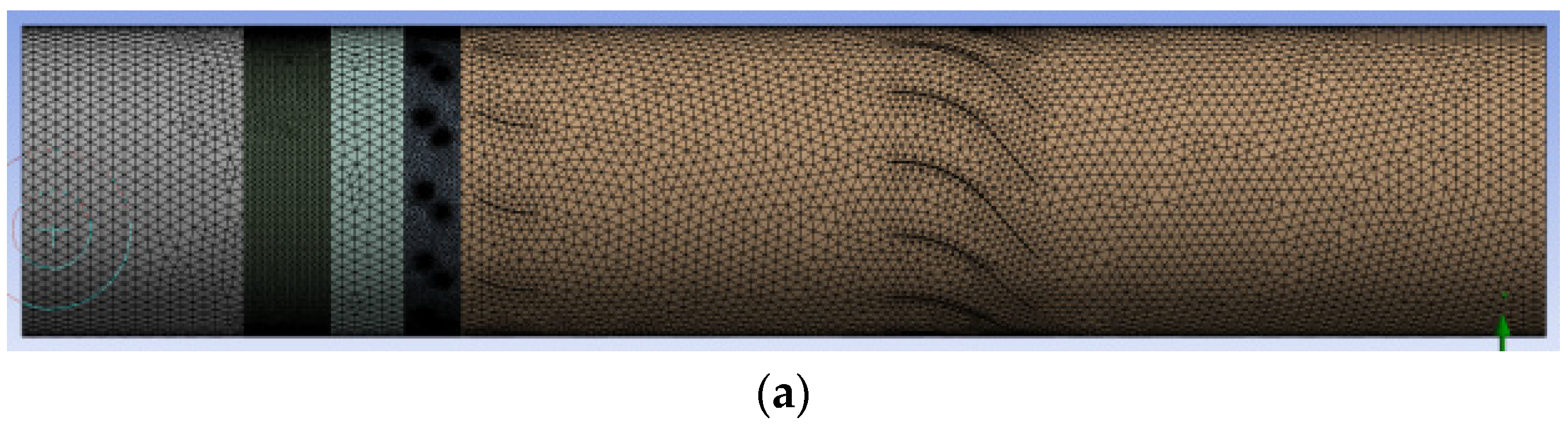
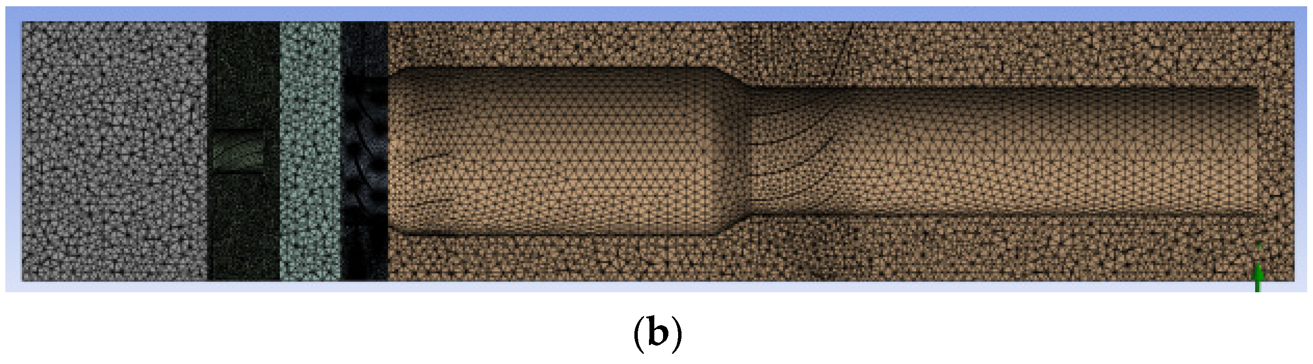
3.4. Grid Division and Independence Verification
The Meshing module of the ANSYS Workbench 2023R1 software was used to conduct unstructured meshing of the fluid domain. To ensure the accuracy of numerical simulation and the convergence of calculations, the grid was refined in the rotation region where the driving impeller and the driven impeller were located. The meshing results are shown in
Figure 4.
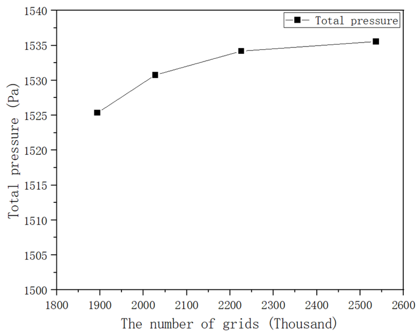
Before the formal numerical simulation, it is necessary to conduct grid independence verification. This involves changing the size of the minimum cell of the grid at the same ratio to obtain four sets of grid models, with grid numbers of 1,894,317; 2,027,718; 2,225,859; and 2,536,249. The quality of the four sets of grids is shown in
Table 2.
The driving impeller speed was set to 2900 r/min, and the inlet speed was set to 16.405 m/s. Subsequently, the four grid models were numerically simulated. The numerical simulation results of the dust removal fan model with four grid numbers are presented in
Table 3.
The total pressure obtained from the numerical simulation of the model with four grid numbers was used as the evaluation index to verify grid independence. The relationship between the total pressure obtained from the numerical simulation of the model with four different grid numbers and the grid number is shown in
Figure 5.
According to the numerical simulation results, when the number of grids reaches 2,225,859, the simulated total pressure value is basically stable. Additionally, it can be observed from
Table 2 that when the number of grids reaches 2,225,859, increasing the number of grids has little impact on improving grid quality. Therefore, the grid division scheme with a grid number of 2,225,859 is selected.
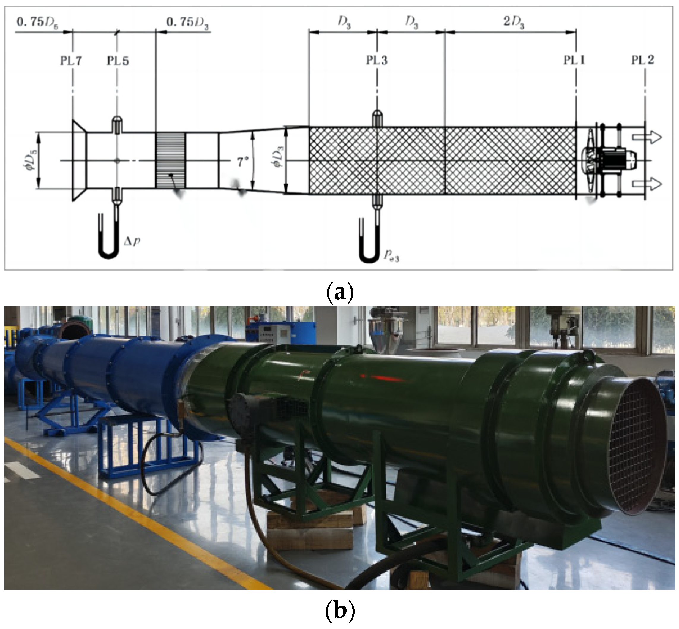
3.5. Comparison of Simulated and Experimental Values
To verify whether the numerical simulation results can reflect the actual working condition of the dust removal fan, we used the test system of the C-shaped conical inlet pipe intake fan to test the dust removal fan. The schematic diagram, test apparatus, and test bench of the C-type pipeline intake test device are illustrated in
Figure 6.
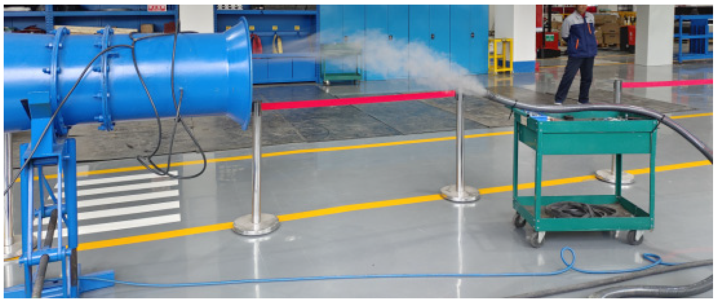
Firstly, the dust removal performance of the dust removal fan was tested. The chosen test material was standard dust with particle sizes ranging from 3 to 20 μm. The dust concentration at the inlet and outlet was measured using a handheld dust concentration tester to calculate the dust removal efficiency. Following the test, the dust removal efficiency of the dust removal fan was found to be 85.44% when the air volume was 396.309 m
3/min. The test process is illustrated in
Figure 7.
Then, parameters of different working conditions were obtained by adjusting the air volume at the cone inlet of the dust removal fan. The test results under four groups of different inlet air volumes were obtained from the data collected during multiple working conditions measured by the test system. The corresponding air volume of each group was converted into the inlet speed of the dust removal fan, and the dust removal fan model was set to the inlet speed for numerical simulation. Four groups of numerical simulation results under different inlet speeds were obtained. These four groups of numerical simulation results are compared with those obtained by the test system, as shown in
Table 4.
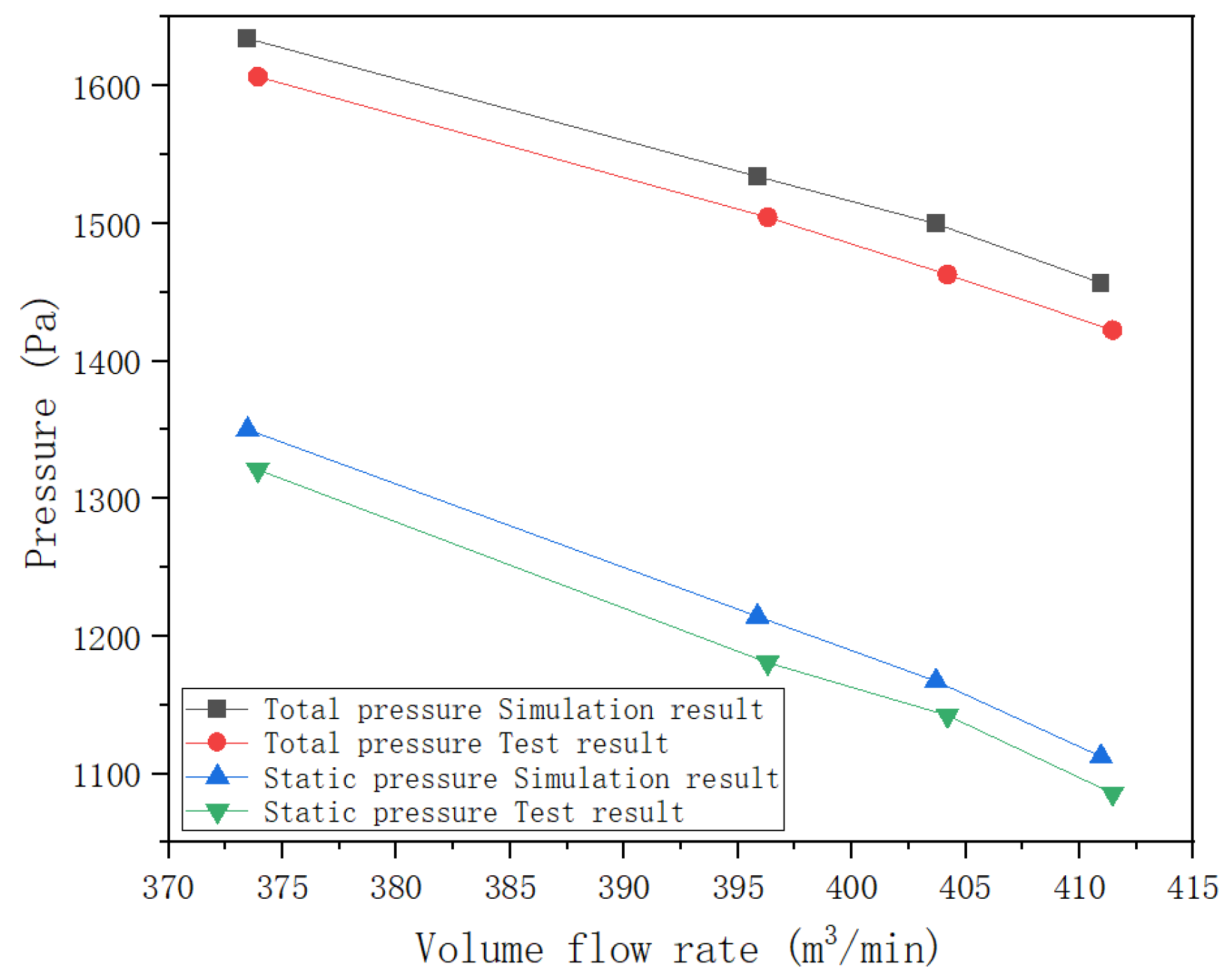
Using the total pressure and static pressure of the dust removal fan as evaluation indicators, we draw a line chart to compare the numerical simulation results and the test results of the total pressure and static pressure of the dust removal fan, as depicted in
Figure 8.
The comparison between the numerical simulation results and the experimental results indicates that the results obtained by the numerical simulation are in good agreement with the experimental results. The change trend of the two is basically the same, and the relative error of the numerical simulation results is less than 5%. Therefore, the numerical simulation method adopted in this paper is accurate and reliable.
4. Numerical Simulation Results and Analysis
4.1. Simulation Cloud Image Analysis
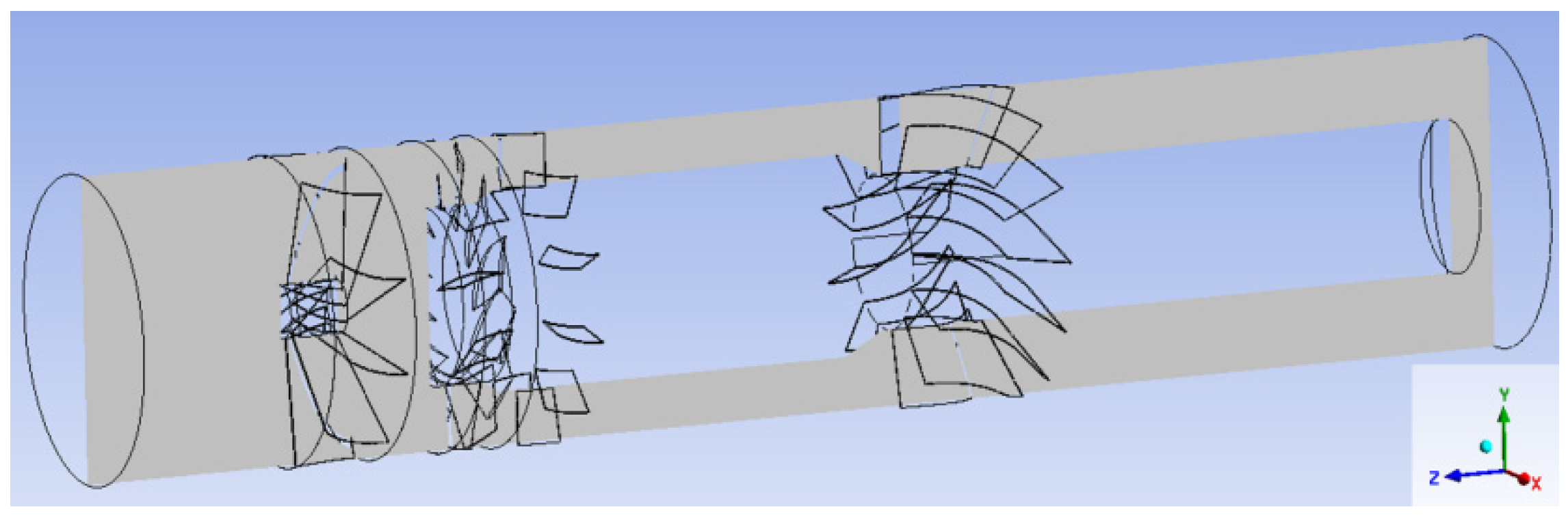
Without altering the structural parameters of the dust removal fan, the numerical simulation cloud image of the original dust removal fan model was analyzed. Initially, an axial section was established in the YZ plane of the model, and the position of the axial section is illustrated in
Figure 9.
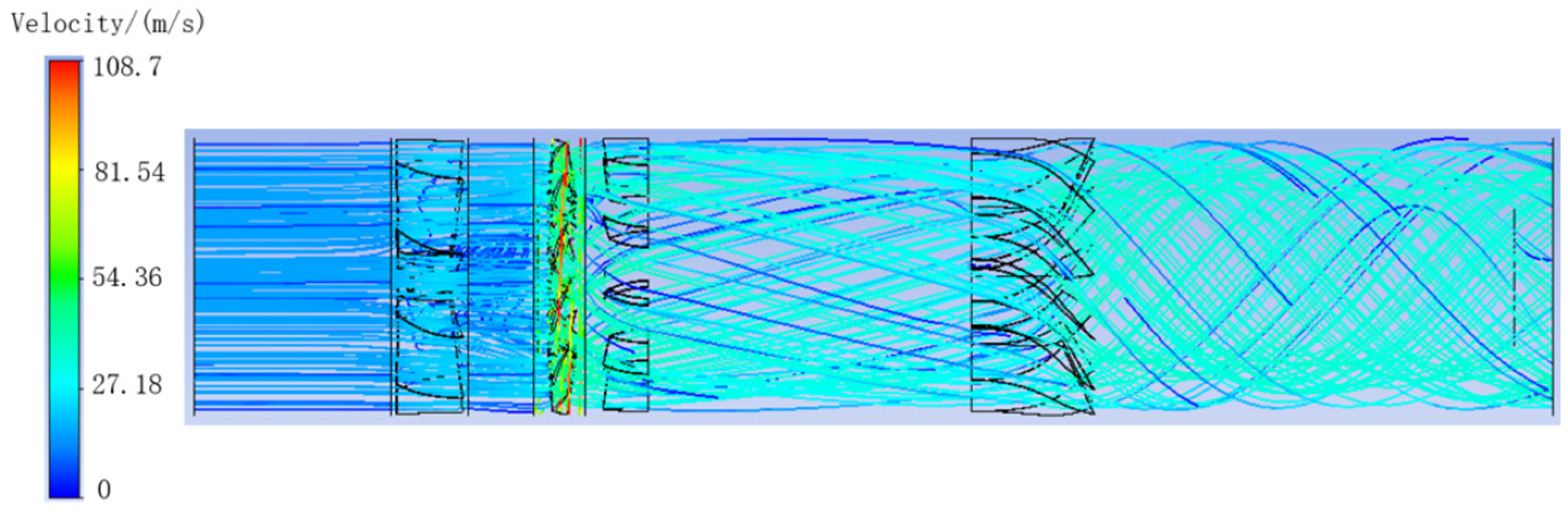
The velocity flow diagram of the dust removal fan model obtained by numerical simulation is shown in
Figure 10.
From the flow diagram of the dust removal fan, it is evident that the air velocity inside the dust removal fan accelerates noticeably after passing through the driving impeller, with the maximum velocity point near the tip of the driving impeller. As the air proceeds through the swirl guide vane, an evident swirling flow is generated in the exit section of the dust removal fan. This swirling flow increases the likelihood of the dust and liquid drop mixture colliding with the side wall of the dust removal fan, thereby aiding in improving the dust removal effect.
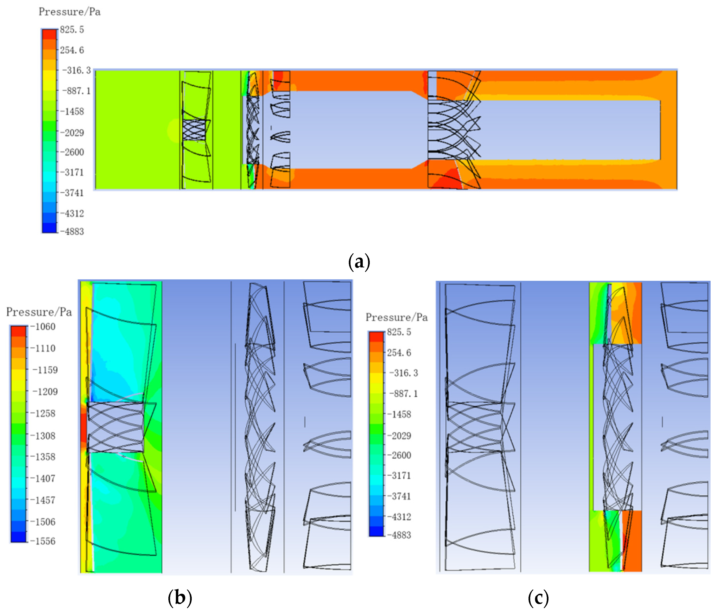
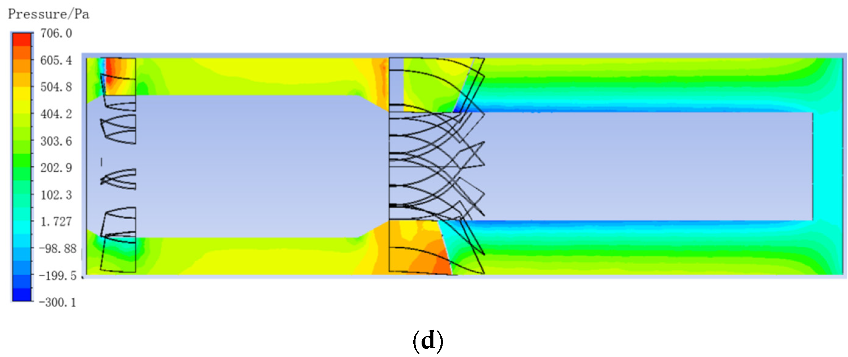
The static pressure cloud image of the entire dust removal fan model and the axial section of each impeller region obtained by numerical simulation are shown in
Figure 11.
From the static pressure cloud image of the axial section of the dust removal fan, it is evident that the static pressure value increases significantly after the airflow passes through the driving impeller blade. The point of maximum static pressure value is located on the lee side of the driving impeller blade, indicating that the blade structure of the driving impeller has the greatest influence on the internal flow field of the dust removal fan. Additionally, when the airflow passes through the rear guide vane and the swirl guide vane, there are also points with large static pressure values on the axial section static pressure cloud image, indicating that the rear guide vane and the swirl guide vane also have a significant influence on the flow field inside the dust removal fan.
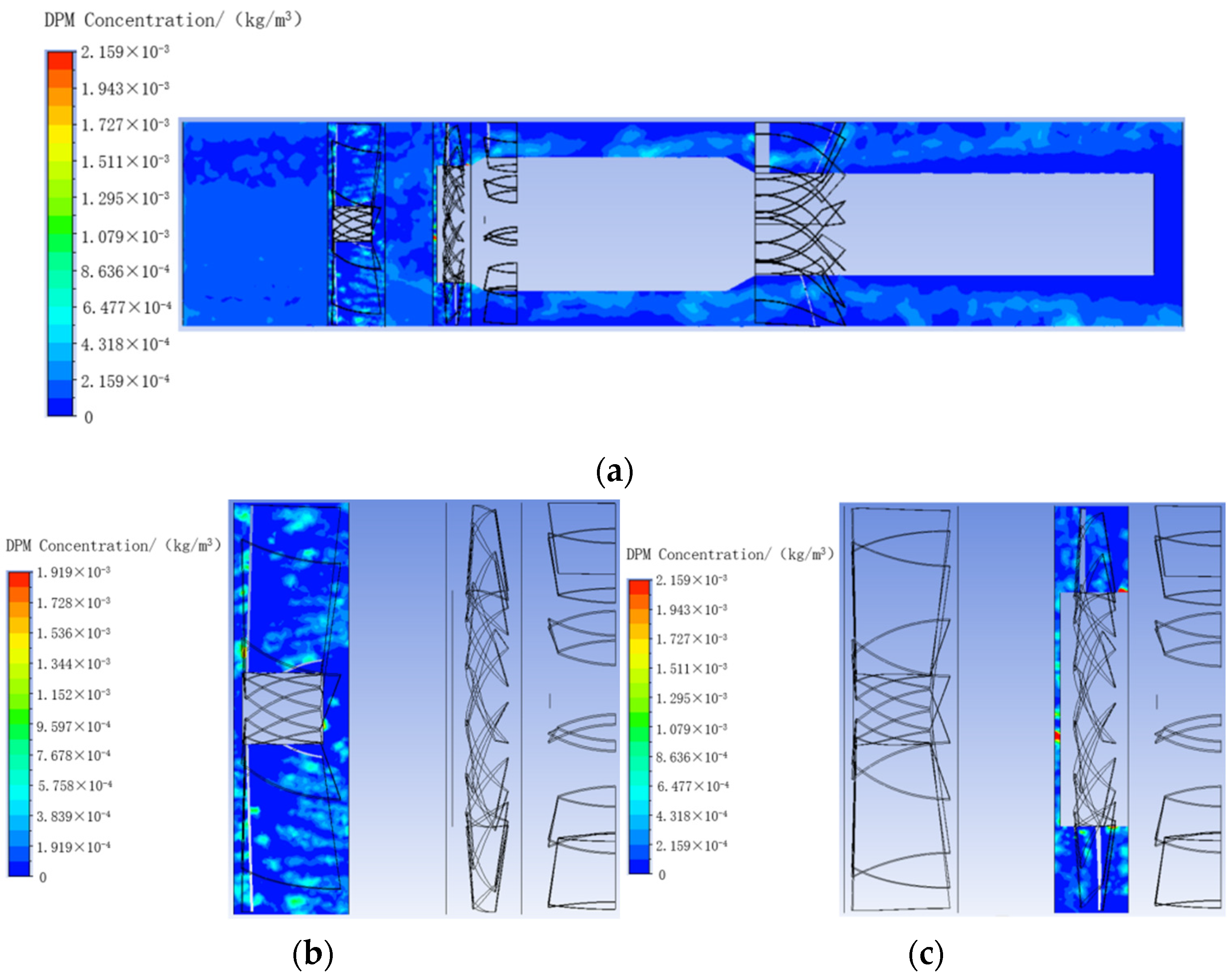
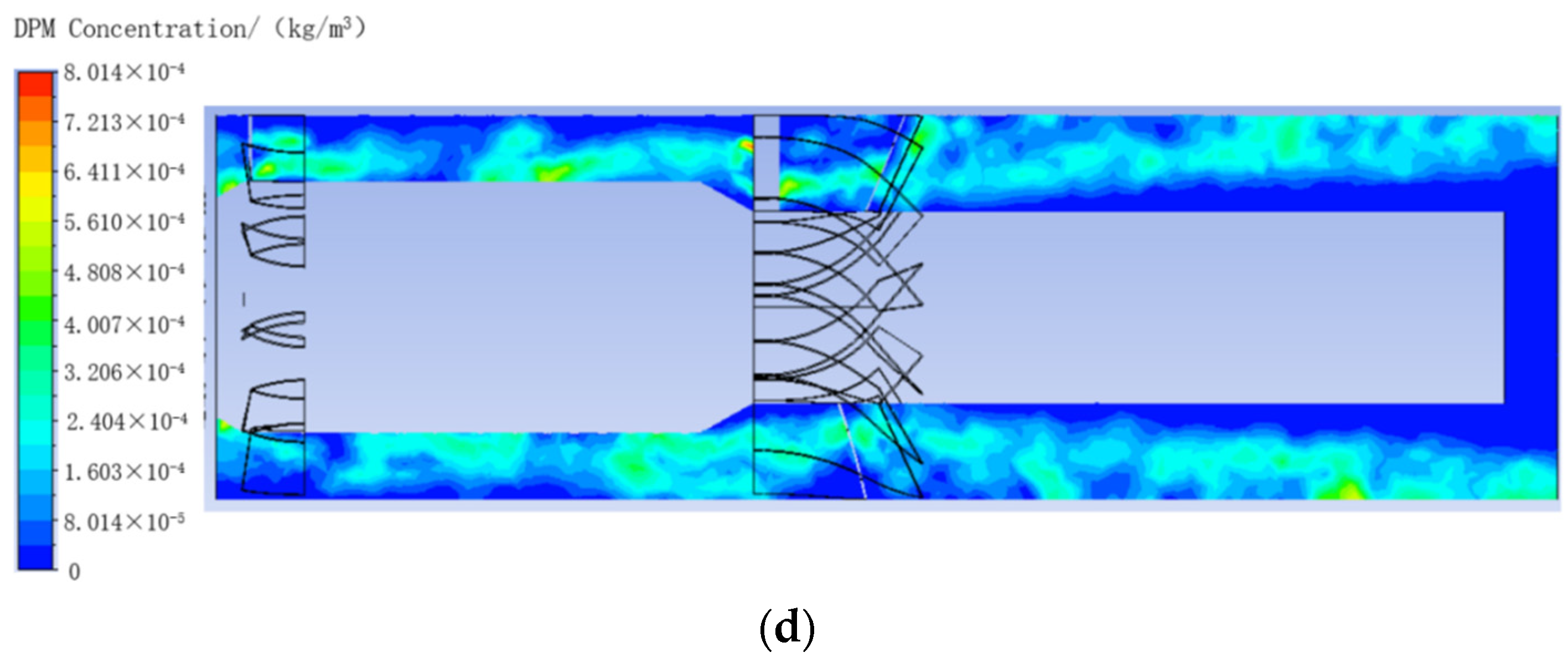
The dust concentration cloud image of the entire dust removal fan model and the axial section of each impeller region obtained by numerical simulation are shown in
Figure 12.
From the dust concentration cloud image of the axial section of the dust removal fan, it can be observed that the point with the highest dust concentration is located near the hub of the driving impeller. Additionally, there is a point with a higher dust concentration near the hub of the driven impeller. This indicates that the dust particles are unevenly distributed before passing through the driving impeller blade, and the distribution begins to become uniform after passing through the driving impeller blade. As the centrifugal force acting on the dust particles increases, their collision with the side wall of the outlet section of the dust removal fan intensifies, leading to a decrease in dust concentration.
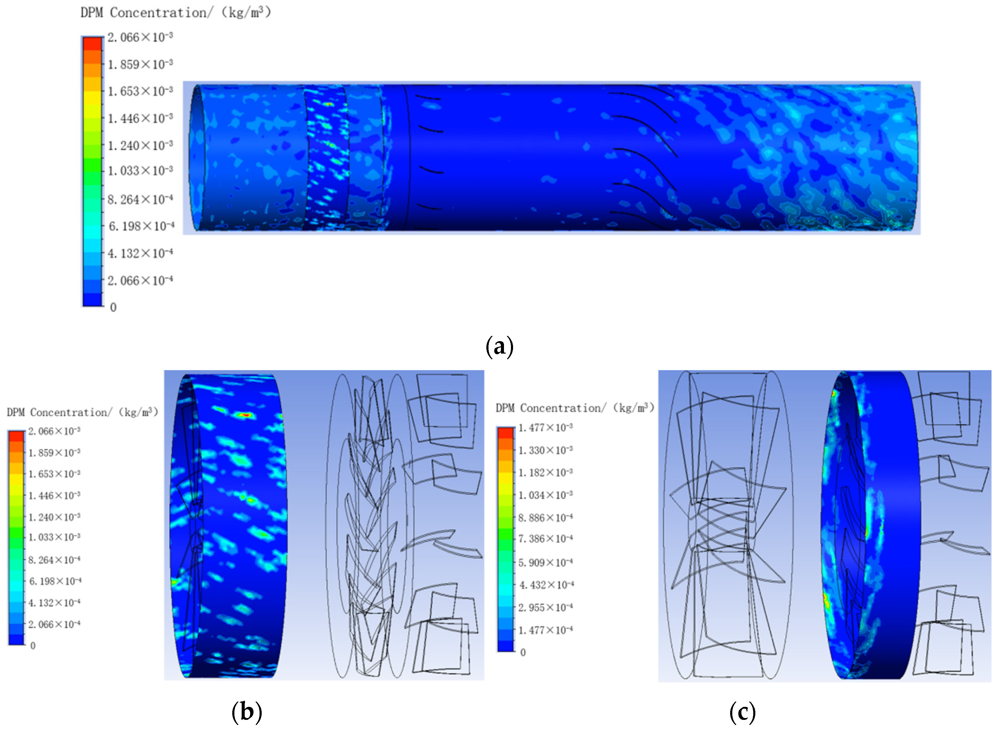
Figure 13 depicts the cloud image of dust concentration on the side wall of the entire dust removal fan model and each impeller region obtained through numerical simulation.
As evident from the cloud image of dust concentration on the side wall of the dust removal fan, the distribution of dust concentration on the side wall of the driven impeller region is highly uneven. The point with the highest dust concentration on the side wall appears at the side wall of the driven impeller region. After passing through the driving impeller blade, the dust concentration at the side wall of the exit section decreases significantly. However, after passing through the swirl guide vane, the dust concentration at the side wall of the outlet section gradually increases. This is because the water film on the side wall of the dust removal fan has a dust trapping effect, leading to a large amount of dust being captured in the outlet section.
4.2. Influence of the Number of Driving Impeller Blades on the Performance of Dust Removal Fan
The number of blades of the driving impeller of the original dust removal fan is 13. Now, keeping the shape of the blades unchanged, six dust removal fan impeller models with different numbers of driving impeller blades are established. The number of blades for each model is shown in
Table 5.
In the numerical simulation of six dust removal fan models with different numbers of driving impeller blades, the inlet speed was set to 16.405 m/s, the speed of the driving impeller was set to 2900 r/min, and the dust particle size was set to 10 μm when the discrete phase was added. The numerical simulation results are summarized in
Table 6.
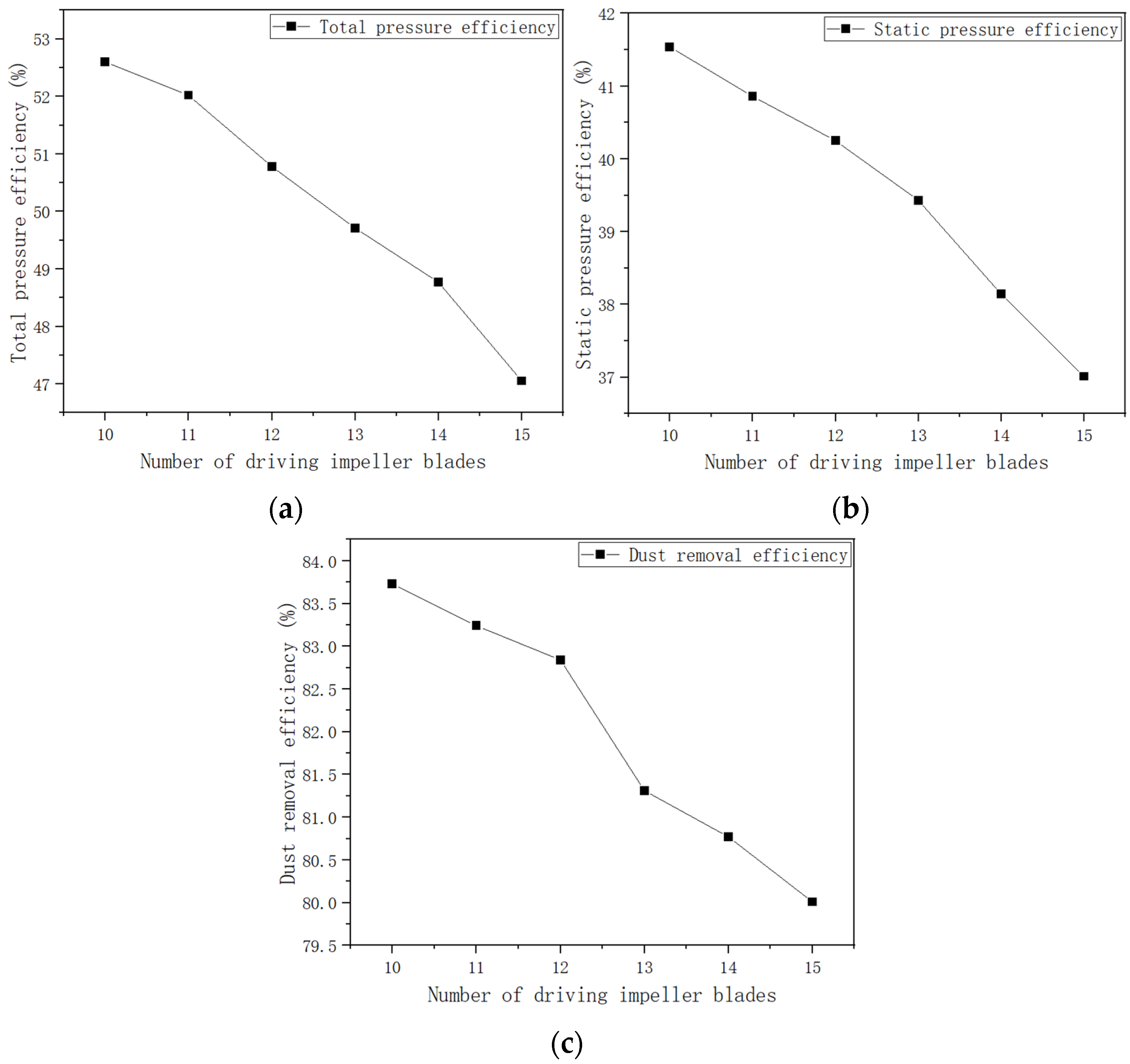
The relationship between the total pressure efficiency, static pressure efficiency, and dust removal efficiency in the table and the number of blades is depicted in a line chart, as shown in
Figure 14.
According to the numerical simulation results, the total pressure efficiency, static pressure efficiency, and dust removal efficiency of the dust removal fan all decrease with an increase in the number of driving impeller blades. This occurs because when the number of dust removal fan blades is too large, the excessive number of blades reduces the flow channel area, obstructing the flow and diminishing the total pressure efficiency and static pressure efficiency of the dust removal fan. Consequently, the decrease in total pressure and static pressure reduces the likelihood of dust particles being captured by the water film on the wall of the dust removal fan, resulting in reduced dust removal efficiency.
4.3. Influence of Driving Impeller Blade Airfoil on the Performance of Dust Removal Fan
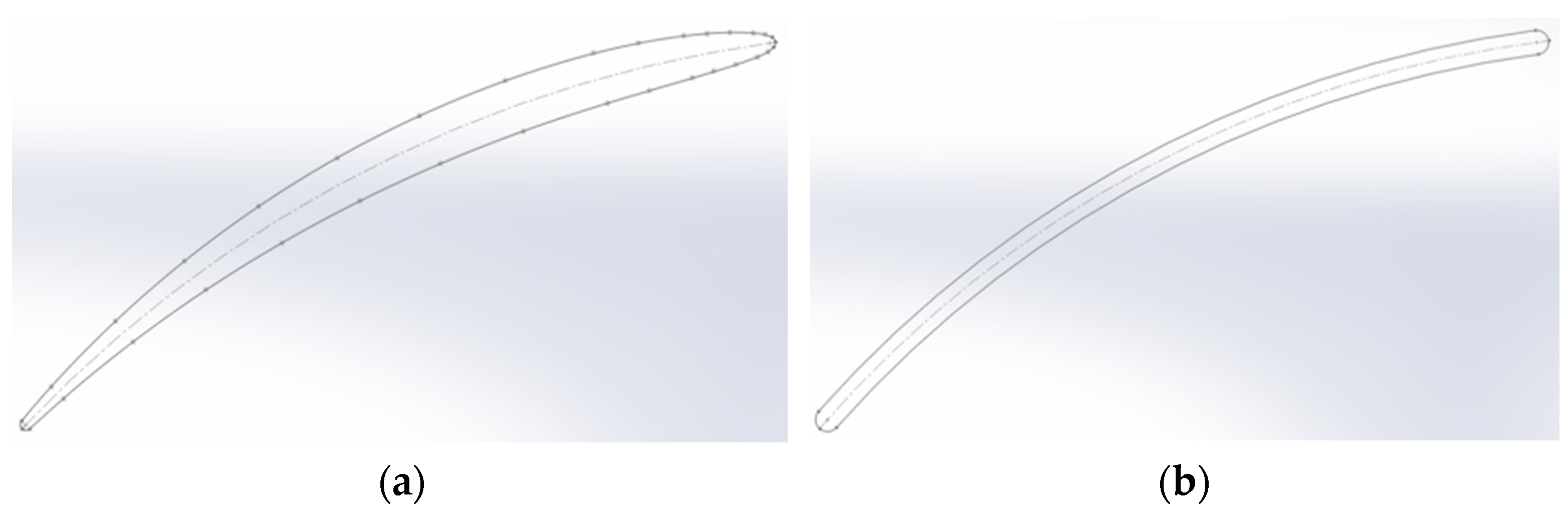
The driving impeller blades of the dust removal fan adopt the C-4 airfoil. To investigate the influence of the driving impeller blade airfoil on the performance of the dust removal fan, impeller models of the dust removal fan using the C-4 airfoil and equal thickness circular arc plate airfoil are established, respectively, without changing other parameters. The blade root cross-sections of the C-4 airfoil and equal thickness circular arc plate airfoil are shown in
Figure 15.
The two driving impeller blades were simulated by dust removal fan models with different airfoil profiles. The inlet speed was set to 16.405 m/s, the driving impeller speed was set to 2900 r/min, and the dust particle size was set to 10 μm during the discrete phase simulation. The numerical simulation results of the dust removal fan model with the C-4 airfoil and equal thickness circular arc plate airfoil are summarized in
Table 7.
According to the numerical simulation results, when the driving impeller blade adopts the C-4 airfoil, the total pressure efficiency and static pressure efficiency of the dust removal fan are higher but the dust removal efficiency is lower compared to the same thickness circular plate airfoil. This occurs because when the driving impeller blade of the dust removal fan adopts the C-4 airfoil, the streamlined structure of the C-4 airfoil effectively reduces the resistance of the driving impeller blade during the rotation process, thus reducing the shaft power of the dust removal fan and improving the total pressure efficiency and static pressure efficiency. Additionally, the C-4 airfoil also reduces the torque exerted by the driving impeller blade on the dust-bearing airflow. This reduction in torque leads to a decrease in the centrifugal force acting on the dust particles, resulting in lower dust removal efficiency. However, despite the reduction in dust removal efficiency, the C-4 airfoil can significantly improve the aerodynamic performance of the dust removal fan. Therefore, the C-4 airfoil is preferred over the equal thickness arc plate airfoil for the driving impeller blade of the dust removal fan.
4.4. Influence of the Number of Driven Impeller Blades on the Performance of Dust Removal Fan
The number of driven impeller blades of the original dust removal fan is 10. Four dust removal fan impeller models with different numbers of driven impeller blades were established. The driven impeller blade numbers of each model are shown in
Table 8.
In the numerical simulation of four dust removal fan models with a different number of driven impeller blades, the inlet speed is set to 16.405 m/s and the speed of the driving impeller is set to 2900 r/min. It is assumed that the mass of the driven impeller remains unchanged at 20 kg for all four models, and the dust particle size is set to 10 μm during the discrete phase simulation. The numerical simulation results are summarized in
Table 9.
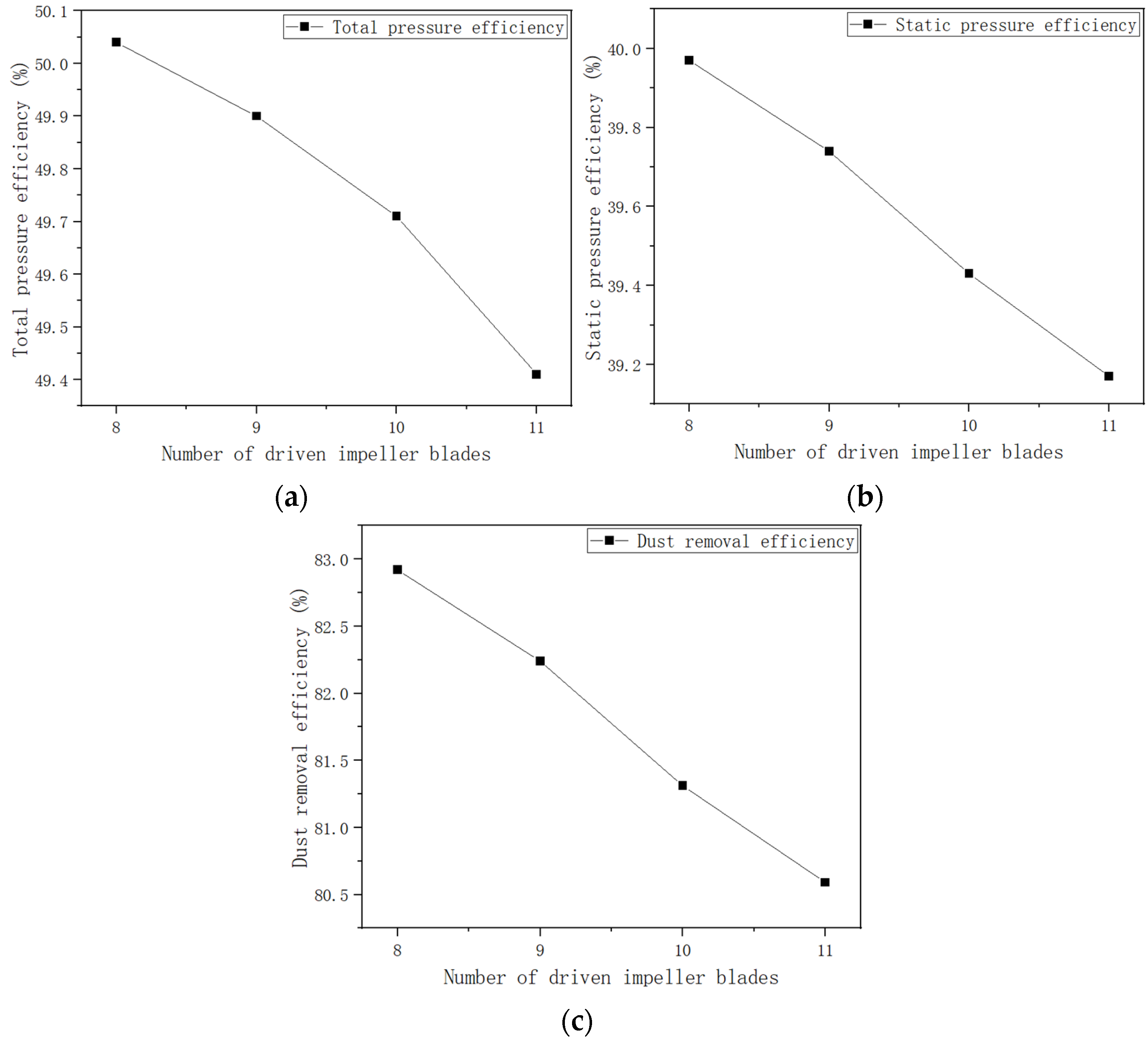
The relationship between the total pressure efficiency, static pressure efficiency, and dust removal efficiency in the table, and the number of driven impeller blades, is drawn into a line chart, as shown in
Figure 16.
According to the numerical simulation results, when the air volume and the mass of the driven impeller remain constant, the shaft power of the driving impeller of the dust removal fan gradually increases with the increase in the number of driven impeller blades, while the speed of the driven impeller gradually decreases. Additionally, the total pressure and static pressure values initially increase and then decrease, and the total pressure efficiency, static pressure efficiency, and dust removal efficiency gradually decrease. This pattern is similar to the change observed in the dust removal fan performance when the number of driving impeller blades decreases. This is because, with the increase in the number of driven impeller blades, the moment of inertia of the driven impeller increases, resulting in a larger shaft power of the driving impeller. However, the change in the number of driven impeller blades has little influence on the total pressure and static pressure values of the dust removal fan, leading to a reduction in both total pressure efficiency and static pressure efficiency. Additionally, increasing the number of blades on the driven impeller reduces the area of the flow channel through which the air flows, hindering the passage of the airflow. This, coupled with the increased moment of inertia of the driven impeller, significantly reduces the speed of the driven impeller. Consequently, the torque exerted by the rotation of the driven impeller decreases the dust particles in the dusty airflow, leading to a reduction in the centrifugal force of the dust particles and a decrease in dust removal efficiency.
4.5. Influence of Rear Guide Vane and Swirl Guide Vane on Performance of Dust Removal Fan
The dust removal fan impeller model with both a rear guide vane and a swirl guide vane, the model with only a swirl guide vane and no rear guide vane, and the model with only a rear guide vane and no swirl guide vane were established for numerical simulation. The inlet speed was set to 16.405 m/s, the rotational speed of the driving impeller was set to 2900 r/min, and the dust particle size was set to 10 μm when the discrete phase was added. The numerical simulation results of the three dust removal fan models are summarized in
Table 10.
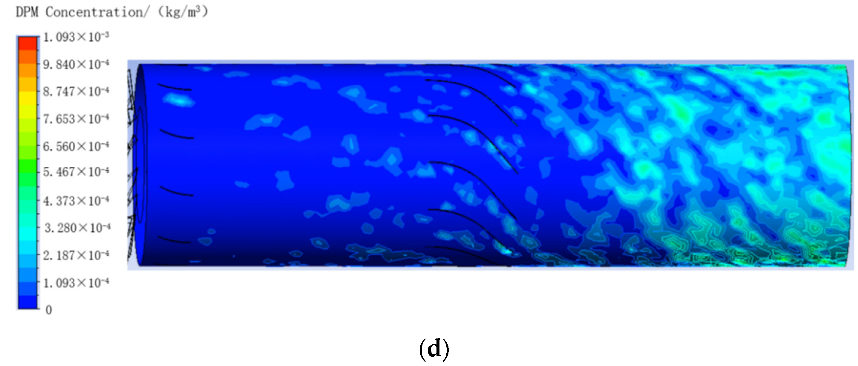
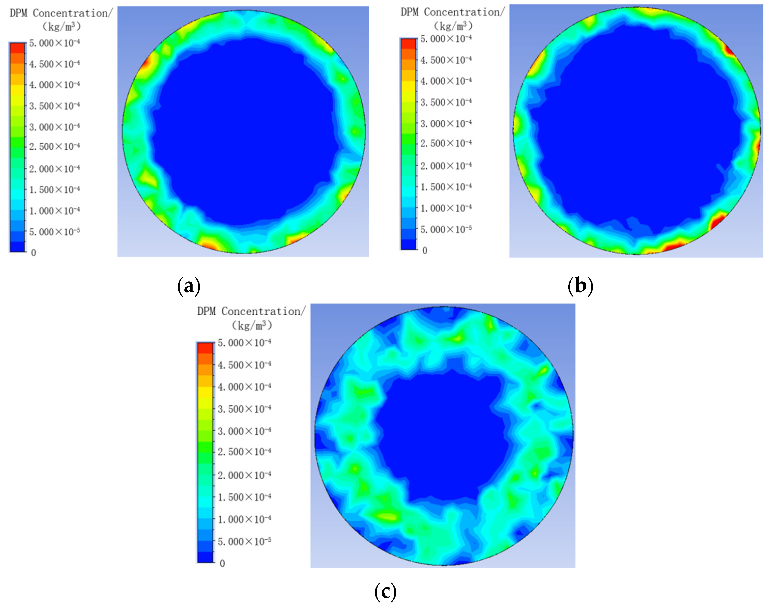
The cloud image of dust concentration at the outlet plane of the dust removal fan model with and without rear guide vane and swirl guide vane obtained by numerical simulation is shown in
Figure 17. For the convenience of comparison, the value range of the three cloud images is set to 0~0.0005 kg/m
3.
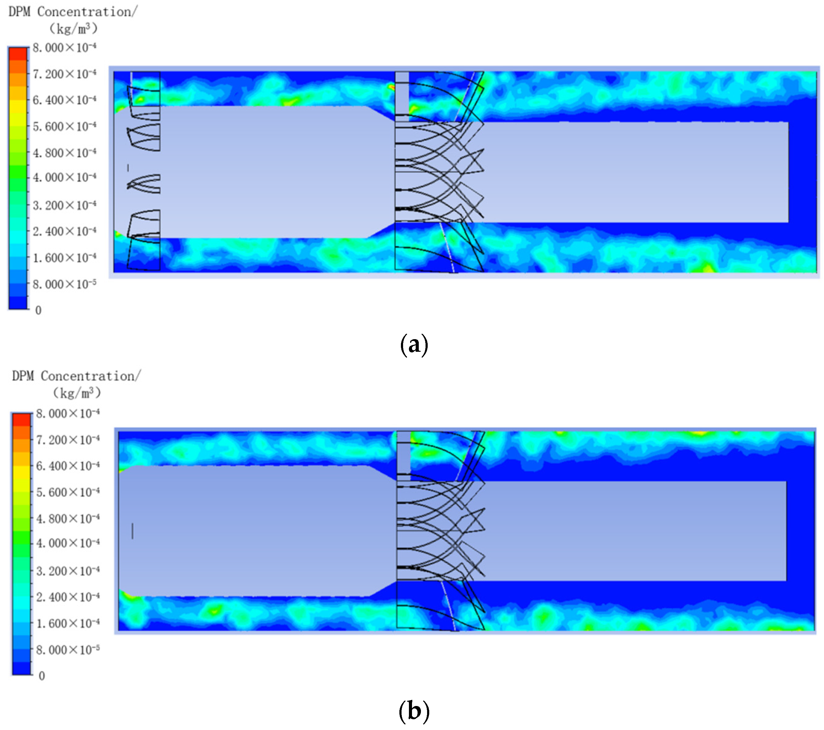
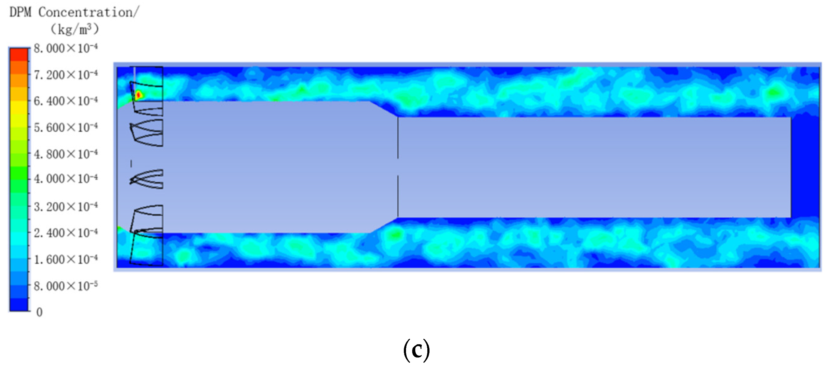
The cloud image of dust concentration in axial section of the outlet section of the dust removal fan model with and without rear guide vane and swirl guide vane obtained by numerical simulation is shown in
Figure 18. For the convenience of comparison, the value range of the three cloud images is set at 0~0.0008 kg/m
3.
According to the numerical simulation results, adding the rear guide vane structure can improve the total pressure efficiency and static pressure efficiency of the dust removal fan but will reduce the dust removal efficiency of the dust removal fan. Based on the dust concentration cloud image of the outlet plane and the axial section of the outlet section of the dust removal fan, when there is no rear guide vane, the dust distribution area at the outlet of the dust removal fan is narrower and the dust distribution in the outlet section is closer to the side wall surface. This occurs because, in the traditional axial fan, the rear guide vane weakens the swirl and improves the total pressure efficiency and static pressure efficiency. However, weakening the swirl also reduces the centrifugal force on the dust particles inside the dust removal fan, decreasing the probability of collision between the dust particles and the water film on the side wall of the dust removal fan, resulting in decreased dust removal efficiency. Therefore, from the perspective of improving the overall performance of the dust removal fan, consideration can be given to canceling the rear guide vane structure.
At the same time, from the numerical simulation results, adding the swirl guide vane structure will reduce the total pressure efficiency and static pressure efficiency of the dust removal fan, but the dust removal efficiency will be significantly improved. According to the dust concentration cloud image of the exit plane and axial section of the dust removal fan, when there is no swirl guide vane, the dust in the exit section of the dust removal fan is distributed throughout the entire flow channel and it is far from the side wall of the dust removal fan. This is because the swirl guide vane of the dust removal fan causes the gas in the outlet section to swirl, increasing the centrifugal force on the dust particles and bringing their movement trajectory closer to the side wall of the dust removal fan. This makes it easier for the dust particles to be captured by the water film on the side wall of the dust removal fan, thereby improving the dust removal efficiency. Therefore, the swirl guide vane is highly beneficial for enhancing the dust removal performance of the dust removal fan.
4.6. Influence of Outlet Length of Dust Removal Fan on Performance of Dust Removal Fan
The total length of the original dust removal fan model from inlet to outlet is 3470 mm. To investigate the influence of the length of the dust removal fan outlet section on the dust removal efficiency, four groups of dust removal fan models with different outlet section lengths are established for simulation. The extension of the outlet section of the four sets of dust removal fan models is shown in
Table 11.
Four sets of dust removal fan models with different outlet lengths were simulated. The inlet speed was set to 16.405 m/s, the driving impeller speed was set to 2900 r/min, and the dust particle size was set to 10 μm when the discrete phase simulation was added. The numerical simulation results of the four groups of dust removal fan models with different outlet lengths are summarized in
Table 12.
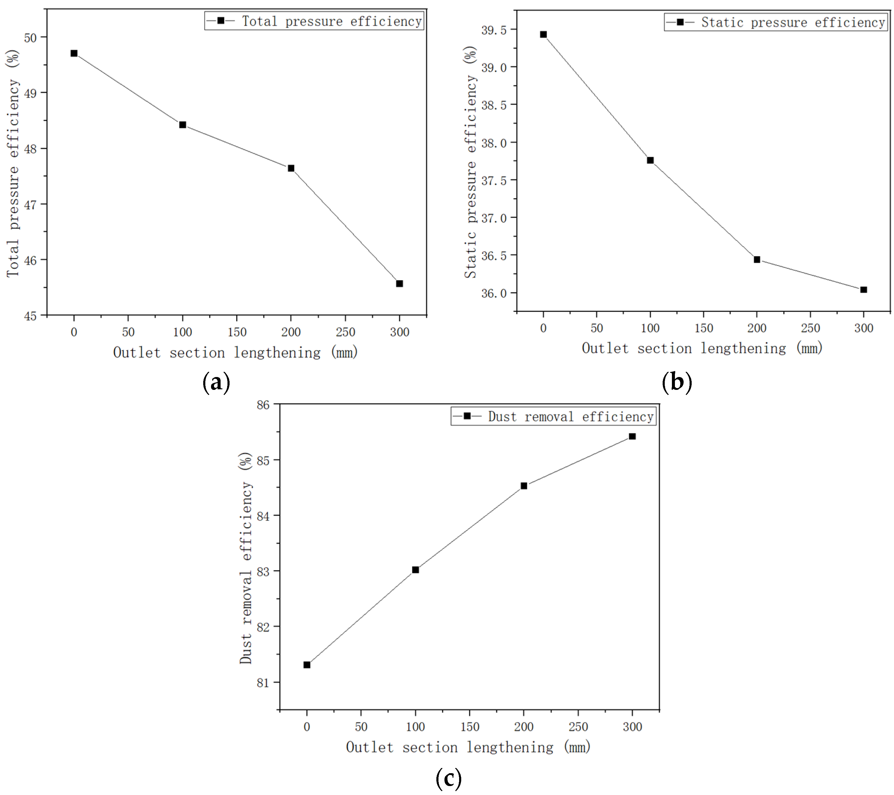
The relationship between the total pressure efficiency, static pressure efficiency, and dust removal efficiency in the table, and the extension of the outlet section of the dust removal fan, is drawn into a line chart, as shown in
Figure 19.
From the numerical simulation results, lengthening the outlet section of the dust removal fan will reduce the total pressure efficiency and static pressure efficiency of the dust removal fan, but the dust removal efficiency will increase. This is because lengthening the outlet section of the dust removal fan increases the resistance of the airflow inside the fan, leading to reduced total pressure and static pressure, thereby decreasing the total pressure efficiency and static pressure efficiency. Additionally, extending the outlet section of the dust removal fan allows for more effective capture of dust in the airflow by the water film on the side wall of the dust removal fan, thereby improving dust removal efficiency. However, extending the outlet section of the dust removal fan increases the overall length of the fan and its footprint. Considering both the extension of the outlet section and the efficiency trends shown in
Figure 19, extending the outlet section of the dust removal fan by 200 mm appears reasonable.


