Article

Numerical Investigation of Droplet Impact on Stationary and Horizontal Moving Surfaces with Superhydrophobic Micro-Pillar Structures

School of Nuclear Science, Energy and Power Engineering, Shandong University, Jinan 250061, China
*
Author to whom correspondence should be addressed.
Appl. Sci. 2025, 15(6), 3188; https://doi.org/10.3390/app15063188
Submission received: 20 February 2025 / Revised: 12 March 2025 / Accepted: 13 March 2025 / Published: 14 March 2025

Abstract

:
Superhydrophobic surfaces with arrayed pillar structures have huge application prospects in various industrial fields, such as self-cleaning, waterproofing, anti-corrosion, and anti-icing. The knowledge gap regarding the liquid–solid interaction between impacting droplets and microstructured surfaces must be addressed to guide the practical engineering applications more effectively. In this study, the effects of the stationary and horizontally moving superhydrophobic micro-pillar surfaces on the droplet impact dynamic behavioral characteristics are investigated numerically, focusing on the droplet morphology, spreading diameter, contact time, and energy conversion. Based on the numerical simulation results, new prediction correlations of the dimensionless maximum spreading diameter for droplets impacting stationary and horizontally moving micro-pillar surfaces are proposed. Moreover, significant rolling phenomena occur when droplets impact horizontally moving micro-pillar surfaces, which leads to an increase in viscous dissipation and forms a competitive mechanism with the asymmetric spreading–retraction process of the droplets. Two different stages are recognized according to the analysis of the contact time and velocity restitution coefficient. This study may provide new insights into understanding the dynamic behavior of droplets on microstructured surfaces.

1. Introduction

In recent years, superhydrophobic surfaces have attracted considerable attention due to their unique surface wetting properties, which have been widely applied in various fields, including self-cleaning surfaces, waterproof and anti-corrosion coatings, anti-icing surfaces, inkjet printing, and energy harvesting [1,2,3,4,5]. Due to the development of high precision manufacturing technology, many artificial superhydrophobic surfaces have been developed by chemical or mechanical processes, such as etching, anodic oxidation, galvanic deposition, electro-spinning, and so on [6,7,8,9,10]. One of them is regular structured surfaces with an array of micro- or nanoscale pillars [11,12,13]. By increasing the roughness, the pillar-arrayed surfaces may reduce the contact angle hysteresis of droplets to make them move easily [14]. These configurations enable droplets to remain in a Cassie–Baxter state, wherein the droplets are suspended on a layer of air and make contact only with the tips of the structures [15]. The spaces between pillars create air pockets that offer a shear-free interface to decrease the viscous dissipation of droplets, enhancing the surface’s water-repellent properties [16,17].
Generally, the impact of a droplet on the micro- or nanoscale pillar-arrayed superhydrophobic surfaces shows a process of spreading, partial or complete rebound, and then shattering probably. Besides the factors that determine the Weber number of droplet, such as the impact velocity and liquid properties, the geometric parameters of the micro- or nanoscale pillars also play vital roles in the droplet impact dynamics. Kwon et al. [18] experimentally investigated the effects of microscale pillars with various patterns on the dynamic behaviors of microdroplet impact. They mentioned that a short inter-pillar spacing results in a larger maximum spreading factor, which means that the surface wettability can be controlled by adjusting the arrangement of the pillars. A similar conclusion has also been reported by Wang and Chen [19] and Zhang et al. [20] that the fraction of the pillars affects the impact processes. Quan and Zhang [12] studied the impact of droplets on different microstructured superhydrophobic surfaces by Computational Fluid Dynamics (CFD). Six kinds of pillars were tested, namely, triangle, square, pentagon, cylinder, cross and sphere. They found that the surface with crisscross pillars has the best bouncing ability. Moreover, a reduced size of the pillars can shorten the contact time when the geometric shape is determined. Liu et al. [21] reported an experiment of droplet impact on the surface with millimeter-scale tapered post arrays. Comparing to straight post arrays, the truncated pyramidal post arrays can reduce the contact time significantly and make the pancake bounce. They also confirmed that the apex angle is a critical parameter to control the drop bouncing behavior. In the study by Lv et al. [22], the regular micro-pillar surfaces were coated further with nanoparticles and organic reagents to produce two-tier roughness. These modified surfaces have good performance in droplet detachment with a high Weber number. Zhang et al. [23] systematically studied the effects of the spacing and height of micro-pillars on the splitting patterns of droplet impact process, and a flow pattern map was proposed. According to their experimental results, the dense, tall pillars suppress the droplet breakup because the gas exhausts from below. To understand the mechanism of droplet impact, molecular dynamics simulation was employed by Gao et al. [24] to investigate the effects of nano-pillar surfaces. Different from the macroscale pillars, they found an exponential relationship between the maximum spreading factor and the Reynold number of the nanoscale pillars. The material of pillars is also a variable factor that leads to different contact angles. For example, Wang et al. [25] reported an experiment of a drop impact on pillar-arrayed surfaces fabricated by polydimethylsiloxane (PDMS). They found that low solid fractions can expand the range of impact velocity for complete bouncing. Other researchers pay attention to the effects of ridges on droplet impact [26,27,28]. The ridge is, in a sense, many pillars that are tightly packed together. The ridge causes the non-axisymmetric spreading and retraction of the droplet, which can reduce the contact time significantly [29,30].
For simplicity, the majority of investigations in the literature have centered on the droplet impact dynamics on the stationary surfaces. In practical applications, however, the surfaces are moving when the droplet impact happens, such as aircraft wings, car windscreens, and turbine blades [31,32,33]. In the study by Almohammadi and Amirfazli [34], the dynamics of drop impact onto moving hydrophilic and hydrophobic surfaces was compared systematically. They reported that the moving surfaces mainly affect the lamellar extension and retraction stages due to spreading and stretching asymmetrically. Furthermore, Buksh et al. [35] observed that the stretching of lamella in the moving direction of solid surface is more obvious for low-surface-tension liquids, such as silicone oil and ethanol. Raman [36] studied the impact of microdroplets on a moving solid surface by the lattice Boltzmann method (LBM). The droplet obtains the momentum imparted by the moving surface, resulting in a breakup of symmetry in the processes of the spreading and recoiling stages. This phenomenon is more pronounced when the droplet impacts the moving surface obliquely. Theoretically speaking, the asymmetric elongation of the drop impacting on a horizontally moving superhydrophobic surface can be attributed to the increased viscous force induced by the entrainment of the air layer [37]. Besides horizontal motion without reciprocating, the solid surface may also vibrate vertically or horizontally when the droplet impacts [38,39]. Under this mode of motion, many other factors should be discussed further, such as vibration frequencies, amplitudes, and phase angles [40,41,42,43,44]. Based on the study by Moradi et al. [45], the phase angle of surface vibration plays a vital role in influencing the droplet impact dynamics, and the rebound velocity is significantly correlated with the vibration frequency and phase angle.
To sum up, previous research often idealizes the conditions of the droplet impact process to simplify the discussion. The combined influences of multiple factors should be proposed and analyzed further. As mentioned above, the regular structured surfaces with an array of micro- or nanoscale pillars are kinds of commonly used superhydrophobic materials. In a real work scenario, the pillar-arrayed surfaces may move, resulting in the destruction of the air layer between the droplet and the pillars. In this study, the effects of the stationary and horizontally moving superhydrophobic micro-pillar surfaces on the droplet impact dynamic behavioral characteristics are investigated numerically, focusing on the droplet morphology, spreading diameter, contact time, and energy conversion. This study aims to deepen the understanding of the interactions between the droplets and solid surfaces, which is beneficial for the optimization of multifunctional surface designs for actual applications.

2. Numerical Method

2.1. Physical Model

Figure 1 shows a 3D physical model of a water droplet impacting on a surface with micro-pillars. The whole calculation domain is rectangular with a size of 130 μm × 110 μm × 65 μm. The bottom of the microstructure and the surface of the microstructure are considered as smooth-wall surfaces and they are set as wall boundary conditions. Wall adhesion is realized by the values of the surface tension and contact angle. The perimeter and top of the computational domain are pressure outlets. An array of micro-pillars is arranged above the bottom wall in 7 rows and 14 columns. The diameter dp of each column is 3.2 μm and the height H is relatively high at 30 μm to capture the behavior of the droplets in the microcolumn. The spacing between two pillars is fixed at 9 μm, which is denoted as dx. To save the computational time, a droplet is located tangentially on the top of the micro-pillar arrays at the initial state with a diameter D0 of 43.7 μm. Furthermore, according to Kwon et al. [46], the surface tension γ and contact angle are set to 0.0683 N m−1 and 110°, respectively, with a droplet viscosity of 1.003 × 10⁻³ Pa s and a density of 998 kg m−3. At the microscopic level, the droplet interacts with the surface and makes it exhibit superhydrophobicity due to the presence of microstructures.
Figure 2 illustrates the definitions of the parameters discussed in this study. For convenient comparison, a series of dimensionless quantities is introduced. The Weber number (We) is usually used to describe the relative importance of inertial forces to surface tension in fluid dynamics. In this study, the characteristic velocity in Weber number is replaced by the initial falling velocity vn and denoted as Wen to describe the droplet, i.e., Wen = ρvn2D0/σ, varying from 0.04 to 9, where ρ is the fluid density, D0 is the initial diameter of droplet, and σ is the droplet surface tension. Furthermore, another transverse Weber number Wet is defined for moving surface, i.e., Wet = ρvt2D0/σ, varying from 0 to 6.4. Here, vt is the horizontal velocity of the micro-pillar surface. Moreover, Hd represents the penetration depth of the droplet. Additionally, the droplet is divided into upstream and downstream sections for subsequent analysis, according to the movement direction of surfaces.

2.2. Numerical Solution

This study uses the commercial CFD software ANSYS Fluent 2022R1 for numerical simulations of the model. The numerical model employs the explicit volume of fluid (VOF) method coupled with a level set function (CLSVOF) to describe the two-phase interface between liquid and air [47]. Considering the low-speed characteristics and incompressibility of the droplets, a pressure-based solver is used to simulate the transient process of droplet impact on the surface. Pressure–velocity coupling is achieved using the PISO scheme, and pressure discretization employs the PRESTO! method. The volume fraction function is discretized using the Geo-Reconstruct scheme, while the momentum equation, energy conservation equation, and level set function are discretized using a second-order upwind scheme. To better approximate real conditions, the simulation includes gravity in the negative y-direction, with a magnitude of g = 9.81 m s−2.

2.3. Governing Equations

The VOF method, first proposed by Hirt and Nichols [48], introduces the volume fraction αi to define the ratio of the ith fluid’s volume to the total volume in each grid cell, i.e.,
α i = V i V c e l l ,
where Vi is the volume of the ith fluid phase in the grid cell and Vcell is the total volume of the grid cell. Moreover,
α i = 1 0 ~ 1 0 ,
where αi = 1 indicates that the grid cell is fully occupied by the ith fluid phase, αi = 0~1 indicates that the interface passes through the cell, and αi = 0 indicates that the grid cell is completely without the ith fluid phase. The evolution equation for the volume fraction α in the VOF method is
α t + ( α u )   = 0 .
The Level Set method was proposed by Osher and Sethian [49] and captures the interface by defining a symbolic distance function ϕ(x,t):
ϕ ( x , t ) = d , in   the   gas   region , 0 , at   the   interface , d , in   the   liquid   region ,
where d is the shortest distance from the interface to the point x. The evolution equation is given by
ϕ t + u ϕ = 0 ,
where u is the fluid velocity vector and ∇ϕ is the gradient of the level set function, indicating the direction of the interface’s normal vector.
The VOF method ensures good conservation of physical quantities, but the volume fraction function α is a discrete quantity, making it difficult to solve accurately, and it requires explicit construction of the moving interface. The Level Set method can implicitly capture interfaces, and the Level Set function remains smooth regardless of changes in the flow field. However, this method is not conservative, leading to a loss of physical quantities during computation, resulting in the smearing of sharp interfaces. To overcome the limitations of both methods, this study uses a coupled Level Set and VOF method, known as the CLSVOF method.
For liquids, the flow governing equation is
u = 0 ,
ρ u t + ρ u u = P + μ [ u + ( u ) T ] σ κ δ ( ϕ ) ϕ + ρ g ,
In this equation, ρ, p, σ, and g represent density, pressure, surface tension coefficient, and gravitational acceleration, respectively. κ is the interface curvature, which can be calculated by the following equation:
κ = ϕ ϕ ,
δ(ϕ) is defined as
δ ( ϕ ) = 1 + cos ( π ϕ / a ) 2 a ϕ < 1.5 ω 0 ϕ 1.5 ω ,
where a = 1.5ω and ω is the minimum grid size.

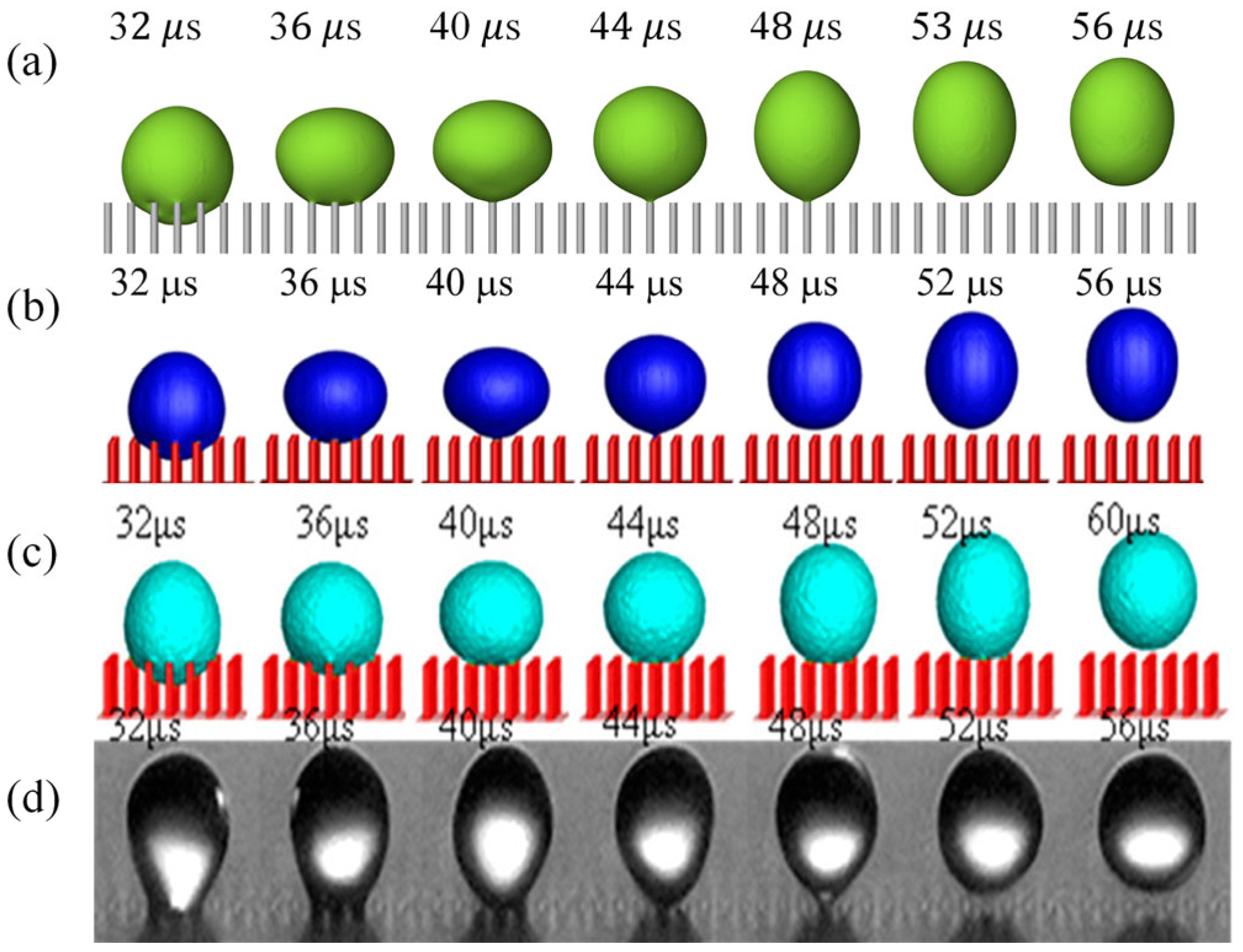
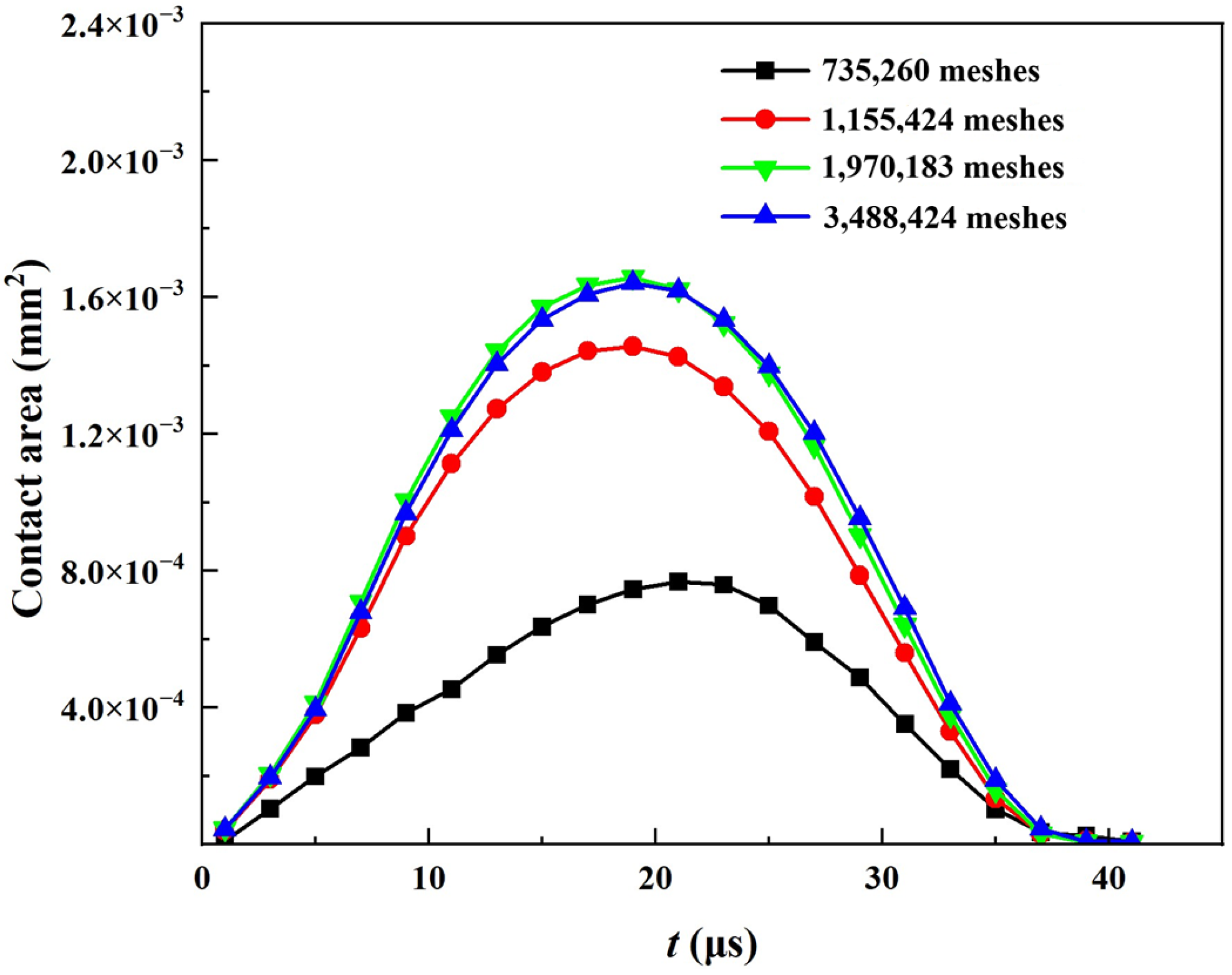
2.4. Model Validation

To verify the accuracy of the method used in this study, a verification model is built with same operational conditions and then compared with the numerical cases [12,50] and experimental results [46] reported in the literature, as shown in Figure 3. Specifically, the domain size is 0.065 mm × 0.065 mm × 0.072 mm. Each cylindrical pillar has a diameter of 3.2 μm and a height of 20 μm. The pitch between two pillars is 9 μm. Moreover, the diameter of the droplet is 43.7 μm, with an initial velocity of 1.68 m s−1. The surface tension and contact angle are set as 0.0683 N m−1 and 110° [46], respectively. The environment is ambient temperature and pressure, no heat transfer is involved in the impact process, and the wall remains stationary. The results indicate that the current model aligns well with the experimental data, especially after 48 μs, where the adhesion behavior at the bottom of the droplet more closely matches the experimental outcomes. During the mesh independence validation, four kinds of grid density are compared, with total grids of 735,260, 1,155,424, 1,970,183, and 3,488,424, respectively. Figure 4 shows the variation in the contact area during the impact process with different numbers of meshes. Considering the balance between computational accuracy and resource consumption, the model with 1,970,183 meshes is selected for this study.

3. Results and Discussion

3.1. Droplet Impact on a Stationary Micropillar Surface

When the Weber number of the droplet impact Wen is relatively low, the droplet cannot penetrate the interior of the micro-pillars. In this scenario, the droplet remains in the Cassie state. As the Weber number increases further, the droplet penetrates the micro-pillar array and infiltrates into the inter-pillar gaps, transitioning into a partial penetration state. The transition between these two states is governed by the balance between the wetting pressure (Pwet) and the anti-wetting pressure (Pantiwet) [46,51]. The wetting pressure comprises two components: the water hammer pressure (PWH) and the dynamic pressure (PD). The water hammer pressure can be calculated using the formula P W H = k ρ C v n , where k is an empirical constant typically set to 0.003, ρ represents the droplet density, and C denotes the speed of sound within the droplet (taken as 1480 m s−1 under standard temperature and pressure conditions). The dynamic pressure is determined by the formula of P D = 1 2 ρ v n 2 . On the other hand, the anti-wetting pressure Pantiwet corresponds to the capillary pressure (PC) of the micro-pillar surface, which can be calculated as follows:
P a n t i w e t = P C = 4 π d p σ sin θ π d p 2 4 d x + d p 2 .
Based on the micro-pillar parameters in this study, the anti-wetting pressure Pantiwet is 1667.93 Pa. When Pwet is less than Pantiwet, the droplet remains in the Cassie state, as illustrated in Figure 5a. Conversely, when Pwet is greater than or equal to Pantiwet, the droplet penetrates the micro-pillar surface and infiltrates downward. Under the operational conditions in this study, the critical velocity for penetration is 0.352 m s−1, corresponding to a critical Weber number of 0.079. When the droplet penetrates the micro-pillar array but does not reach the bottom surface, it is in a partial penetration state, as shown in Figure 5b. With a further increase in the Weber number, the droplet transitions from partial penetration to the Wenzel state [11] upon contacting the bottom surface, as depicted in Figure 5c. Consequently, the maximum penetration depth (Hmax) during the whole impact process serves as a crucial parameter for characterizing the droplet state. We define the dimensionless maximum penetration depth as H* = Hmax/H. As shown in Figure 6a, the dimensionless maximum penetration depth gradually increases with increasing impact velocity. Below the critical penetration velocity, the maximum penetration depth is primarily influenced by droplet surface oscillations and curvature [52]. A plateau region is observed within the velocity range of 2 to 3 m s−1 (corresponding to Wen between 3 and 5.4), where the maximum penetration depth no longer increases. This phenomenon arises because the droplet volume remains constant while the spreading diameter increases, causing the kinetic energy to be converted into the droplet’s lateral spreading capability.
Richard et al. [53] found that the contact time of a droplet impacting on smooth planar surface is determined solely by its diameter and the properties of the liquid, independent of the impact velocity, i.e., τ c ( ρ D 0 3 / 8 σ ) 1 / 2 . Based on this relationship, the dimensionless contact time is defined as t * = t c / τ c as a comparison between the smooth and micro-pillar surfaces, where tc represents the actual contact time of the droplet impact in this study. As shown in Figure 6b, the contact time exhibits various trends under different droplet states, which differs from the trends when droplets impact millimeter-scale microstructured surfaces [54]. In the Cassie state, due to the low kinetic energy of the droplet, the kinetic energy is insufficient to overcome the surface adhesion, although the micro-pillar surface is hydrophobic, preventing the droplet from bouncing off the surface. In the partial penetration state, as the impact velocity increases, the contact time first decreases and then increases. This trend is also observed in the study by Quan and Zhang [12], where the contact time varies parabolically with velocity. This is primarily because, at lower velocities, the retraction behavior is slower, leading to longer contact times. As the velocity increases, the retraction accelerates, and the contact time reaches a minimum. As the velocity continues to increase, considering the relatively high micro-pillar height in this study, when the droplet penetration depth becomes too large, viscous dissipation increases, and the distance the droplet needs to travel to retract from the surface becomes longer, resulting in an increase in contact time again. In the Wenzel state, within the Weber number range of this study, the high micro-pillar height leads to excessive energy dissipation, causing the droplet to eventually become trapped within the micro-pillar array (as shown in Figure 5c). In this state, the contact time tends to infinity, similar to the Cassie state.
The dimensionless maximum spreading diameter during droplet impact on a stationary wall is defined as D 0 * = D m a x / D 0 , where Dmax represents the maximum diameter of the droplet during impact. The dimensionless maximum spreading diameter for droplet impact on a stationary microstructured wall satisfies the universal formula proposed by Aboud and Kietzig [55], that is,
D 0 * = ( a W e n ) b ,
where the parameters a and b take different values depending on the surface conditions. As shown in Figure 7, referring to this form, a dimensionless maximum spreading diameter formula for droplet impact on a stationary micro-pillar surface is fitted based on the data obtained in this study, which is given as follows: D 0 * = ( 0 . 47 W e n ) 0 . 15 . The R2 value of this fitting formula is 0.97, indicating that the formula provides a good description of the trend of D 0 * with respect to Wen.

3.2. Droplet Impact on Horizontally Moving Micro-Pillar Surfaces

3.2.1. Droplet Impact Behavior

Figure 8 shows the velocity distribution during a droplet impacting on a moving surface with different horizontal velocities. When a droplet impacts a moving surface with the partial penetration state, its dynamic behavior can be divided into the following stages, as shown in Figure 8a. Firstly, during the spreading stage, the kinetic energy of the droplet is gradually converted into surface energy, causing the spreading diameter of the droplet to continuously increase. Simultaneously, the droplet penetrates into the gaps between the micro-pillars, compressing the air within these gaps (t* = 1.14). When the kinetic energy of the droplet in the vertical direction drops to zero (t* = 1.70), the penetration stage of the droplet ends. Subsequently, the surface energy is reconverted into kinetic energy, and the droplet begins to rapidly retract and gradually detach from the micro-pillar surface. If the droplet’s kinetic energy is sufficiently large, it will eventually completely bounce off the surface (t* = 3.49). As Wet increases, the horizontal momentum of the droplet increases, causing the droplet to exhibit horizontal displacement relative to its initial impact position upon detachment, as shown in Figure 8b. Additionally, it can be observed that in the upstream region within the micro-pillar gaps, there are upward-tilting velocity vectors, while in the downstream region, there are downward-tilting velocity vectors. This phenomenon reveals the velocity changes during the droplet’s rolling process (as shown in Figure 8b, t* = 1.70).
Droplets undergo contact, spreading, retraction, and rebound processes when impacting both moving and stationary surfaces [31]. However, when a droplet impacts a horizontally moving micro-pillar surface, a unique rolling phenomenon occurs, where the upstream portion of the droplet detaches from the micro-pillar surface while the downstream portion continues to penetrate into the micro-pillar gaps, as shown in Figure 9. This phenomenon arises because the droplet possesses both upward and horizontal momentum during the rebound stage. Due to the presence of air at the bottom, the downstream portion of the droplet can continue to penetrate downward, while the upstream portion is subjected to surface tension and capillary forces, causing it to contract upward. This results in the droplet rolling along the horizontal direction. The magnitude of Wet influences the degree of rolling within the micro-pillar gaps, with greater rolling leading to more significant energy dissipation. Therefore, an increase in Wet not only exacerbates the asymmetry of the droplet [56], making it more likely to bounce off the surface, but the presence of the rolling phenomenon also suppresses the droplet’s bouncing behavior. The final effect of Wet is a compromise of the above two influences.
The pressure peak is closely related to the droplet’s motion behavior [57]. The first pressure peak generated at the moment of droplet impact causes the droplet to rapidly change its motion state, initiating spreading or penetration. The second pressure peak is associated with the droplet’s recoil and jetting phenomena, influencing the rebound direction and speed of the droplet. As shown in Figure 10, in the model of this study, the pressure peaks during droplet impact on both stationary and moving micro-pillar surfaces occur at the top of the micro-pillars. This is because the top region of the micro-pillars transitions abruptly from a wide open space to a narrow micro-pillar space, causing a sharp change in the fluid direction and generating vortices, which in turn create pressure peaks at this location. Furthermore, it can be observed that the pressure peak is smaller when the droplet impacts a surface with horizontal motion compared to a stationary surface. This is because the impact energy of the droplet is more concentrated in a localized area when the surface is static, whereas on a horizontally moving surface, part of the energy is dispersed due to the motion of the surface, thereby reducing the magnitude of the pressure peak.

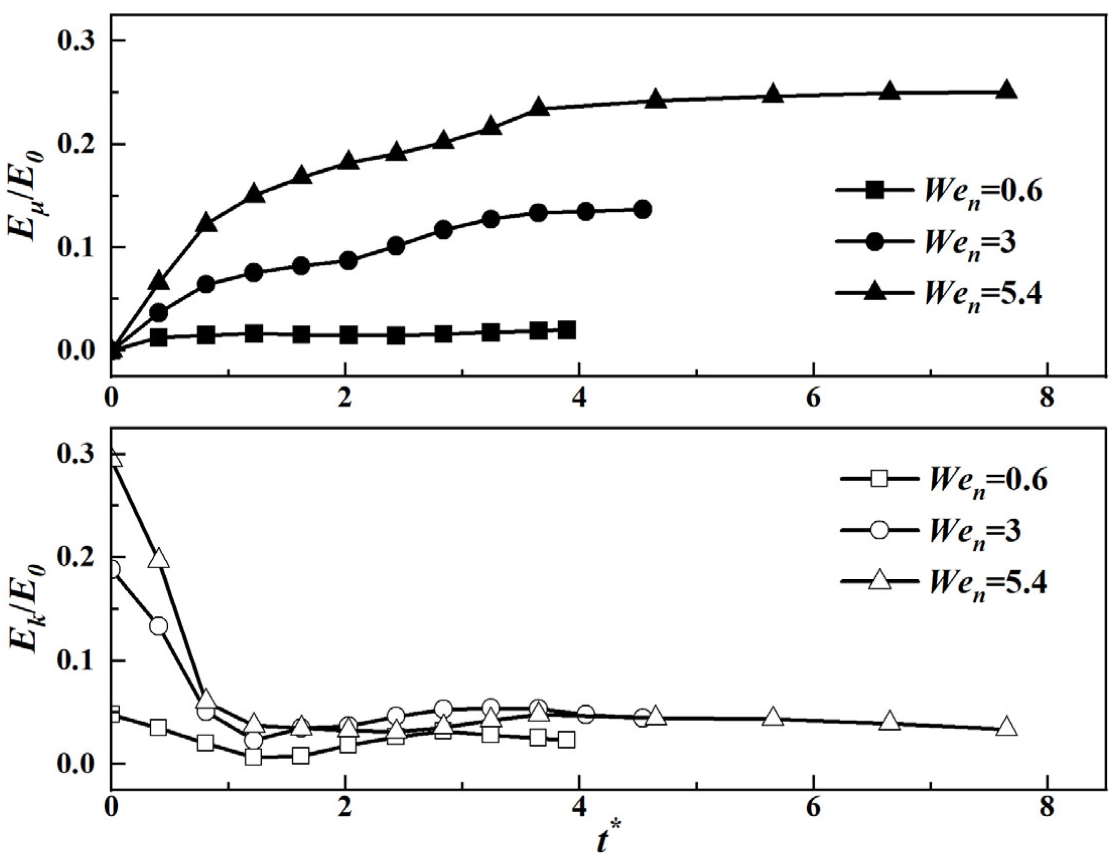
3.2.2. Velocity Restitution Coefficient and Energy Dissipation

When the droplet bounces off from the surface, the speed of takeoff v is a key parameter and the restitution coefficient εn is introduced as v / v n to illustrate the droplet dynamic characteristics. Biance et al. [58] studied the velocity restitution coefficient εn of droplet impact on heated silicon surfaces and derived it by establishing the spring model ε n = a W e n 0.5 . Aria and Gharib [59] established a similar correlation for droplet impact on stationary smooth superhydrophobic surfaces as ε n = a W e n 0.25 . Subsequently, Aboud and Kietzig [60] studied the droplet impact on inclined surfaces and proposed that ε n = 1.2 W e n 0.12 . Additionally, Qian et al. [54] summarized a correlation for the longitudinal restitution coefficient of droplet impact on horizontally moving grooved surfaces as ε n = 1.45 W e n 0.5 . However, due to the difference in the microstructure on the surface, the variation in the velocity restitution coefficient during droplet impact in this study exhibits a different trend, as shown in Figure 11. Specifically, when micrometer-sized droplets impact micro-pillar surfaces, the velocity restitution coefficient does not follow the form of ε n = a W e n b . The velocity restitution coefficient is mainly divided into two stages. First, as Wen increases, the velocity restitution coefficient εn rapidly decreases (as indicated by the pink region), dropping from approximately 0.5 to around 0.25. As Wen further increases further, the restitution coefficient εn fluctuates between 0.2 and 0.3 (as indicated by the light blue region). This trend differs from the impact behavior of millimeter-sized droplets in which the velocity restitution coefficient of millimeter-sized droplets typically continues to decrease with increasing Wen. The occurrence of this phenomenon is attributed to the fact that, within this range of impact Weber numbers (Wen = 3–5.4), the penetration depth of the droplet remains almost constant, as shown in Figure 6a. Therefore, the differences in viscous dissipation caused by variations in micro-pillar height can be neglected, and the velocity restitution coefficient remains within a relatively stable range. The fluctuations in the velocity restitution coefficient are primarily due to changes in the spreading diameter and the varying degrees of droplet rolling.
The previously mentioned contact time and velocity restitution coefficient are related to the competition between kinetic energy and dissipated energy, prompting us to conduct an energy analysis of the model in this study. The total energy during droplet impact mainly includes kinetic energy Ek, surface energy Es, gravitational potential energy Eg, and dissipated energy Eμ. According to energy conservation, the following relationship should be satisfied:
E 0 = E k + E s + E g + E μ ,
where E0 is the total energy of the droplet in its initial state. Ek can be calculated by an integral of each mass element’s kinetic energy. The surface energy Es of the droplet is given by
E s = A lv σ lv + A ls ( σ ls σ sv ) .
According to Young’s equation that σ s v σ l s = σ l v cos θ , we have E s = σ lv ( A l v A l s cos θ ) , where A represents the contact area and the subscripts l, v and s are liquid, gas and solid, respectively. Since the change in gravitational potential energy in this study is two orders of magnitude smaller than that in kinetic energy and surface energy, the gravitational potential energy Eg is neglected. The dissipated energy Eμ is obtained with the total energy in the initial state minus the sum of kinetic energy and surface energy. By normalizing these energy terms with respect to the total energy in the initial state, dimensionless quantities are obtained. As shown in Figure 12, along with Wen increasing, the proportion of energy dissipation also gradually increases. This is because the increases in droplet penetration depth and spreading diameter lead to greater viscous dissipation during the spreading and retraction processes. Meanwhile, the dimensionless kinetic energy decreases rapidly with increasing Wen, which explains the variation in the velocity restitution coefficient. The greater the initial kinetic energy of the droplet, the deeper the penetration depth, resulting in increased dissipated energy and ultimately causing the dimensionless kinetic energy of the droplet to remain almost unchanged upon leaving the surface.

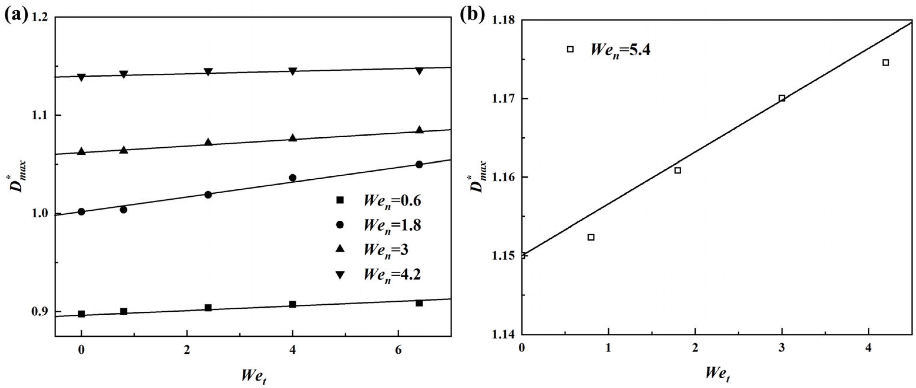
3.2.3. Maximum Spreading Diameter
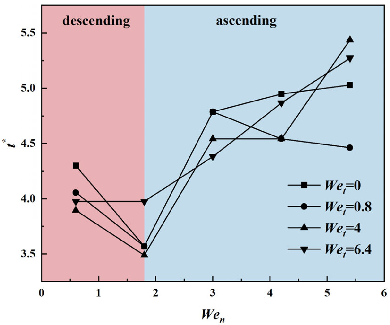
Aboud and Kietzig [55] reported that when a droplet slides on an inclined superhydrophobic surface, the adhesion caused by solid–liquid contact leads to droplet stretching, thereby increasing its maximum spreading diameter. Additionally, they emphasized the dynamic pressure ( P d = ρ v n 2 ) during impact, and based on these considerations, they derived the formula for the maximum spreading diameter of a droplet impacting an inclined superhydrophobic surface, that is,
D max * = D 0 * + c t a n ( A O I ) W e n 1 / 2 ( ρ v n 2 ) ,
where c is the adhesion coefficient, AOI is the angle of incidence, and D max * is the dimensionless maximum diameter during droplet impact on a moving surface, which is defined as D max * = D max / D 0 . Similarly, Qian et al. [54] combined extensive experimental data to summarize a model for droplet impact on horizontally moving grooved surfaces, that is,
D max * = D 0 * + c v t 2 / v n W e n 1 / 2 ( ρ v n 2 ) ,
where the term c v t 2 / v n W e n 1 / 2 ( ρ v n 2 ) represents the additional contribution from the moving wall. However, since the scale of the droplet and surface in this study is on the micron order, which is much smaller than millimeter-sized droplets, the proportional relationship of the internal forces differs significantly. The Laplace stress at the micrometer level cannot be neglected because the smaller the droplet diameter, the greater this force [61]. Moreover, the micro-pillar structure is distinguished from the grooved surfaces in that the array of pillars allows the fluid to pass through the spaces between pillars. According to the data obtained in this study, it can be concluded that when micrometer-sized droplets impact horizontally moving micro-pillar structured surfaces, the dimensionless maximum spreading diameter is proportional to Wet, as shown in Figure 13a. Based on this relationship, a new model is proposed for the maximum spreading diameter of micrometer-sized droplets impacting horizontally moving micro-pillar surfaces, that is,
D max * = D 0 * + a W e t W e n b .
This formula incorporates the dynamic pressure and Laplace stress during droplet impact and is expressed using dimensionless parameters. Fitting the model based on the summary of a large number of simulation, the factors can be determined as D max * = D 0 * + 0.014 W e t W e n 0.45 . To validate the rationality of this formula, more cases with Wen = 5.4 are simulated and the results are shown in Figure 13b, which exhibits a good robustness of the proposed predictive correlation.

3.2.4. Contact Time

When droplets impact moving surfaces or surfaces with directional anisotropy, the droplets experience asymmetric spreading and retraction in two directions, forming a short axis and a long axis [56,62]. Typically, the short axis of the droplet retracts earlier than the long axis; so, when the short axis retracts to its minimum, the droplet detaches from the surface. For example, when a droplet impacts a moving surface, the long axis of the droplet extends along the direction of motion, while the short axis is perpendicular to the direction of motion. The model in this study not only considers the horizontal motion velocity of the droplet, but also accounts for the droplet penetrating into the micro-pillar space and undergoing a rolling phenomenon. This rolling phenomenon leads to additional viscous dissipation, making the contact time model in this study more complex. Figure 14 shows the variation in the droplet contact time with Wen, which is mainly divided into two stages.
First, in the range of 0.6 < Wen < 1.8, the contact time decreases as the Wen increases. At this stage, the penetration depth of the droplet is relatively small, and the viscous dissipation effect caused by droplet rolling is not significant, leading to a reduction in the contact time. Second, in the range of 1.8 < Wen < 5.4, the contact time increases with the Wen. Here, the penetration depth of the droplet increases, resulting in greater viscous dissipation. Although the droplet exhibits asymmetry during spreading and retraction, the contact time still increases with the Weber number. Therefore, the contact time model in this study is essentially the result of competition between viscous dissipation caused by the rolling phenomenon and asymmetric spreading. The rolling phenomenon increases energy dissipation during droplet contact, while asymmetric spreading promotes droplet retraction and detachment from the surface. The interaction between these two factors determines the contact time of the droplet.

4. Conclusions

This study investigates numerically the dynamic process of micrometer-sized droplets impacting horizontally moving micro-pillar surfaces. The dynamic behavior and key parameters are discussed based on the cases with different Wen and Wet values. This study enriches the understanding of the dynamic behavior of droplets impacting horizontally moving superhydrophobic surfaces. This will help to improve the control of wettability on horizontally moving microstructured surfaces. Future development of this research could focus on extending numerical models to investigate dynamic surface topology, coupled multiphysics field effects, and droplet dynamic behavior in extreme environments. The main conclusions are as follows:
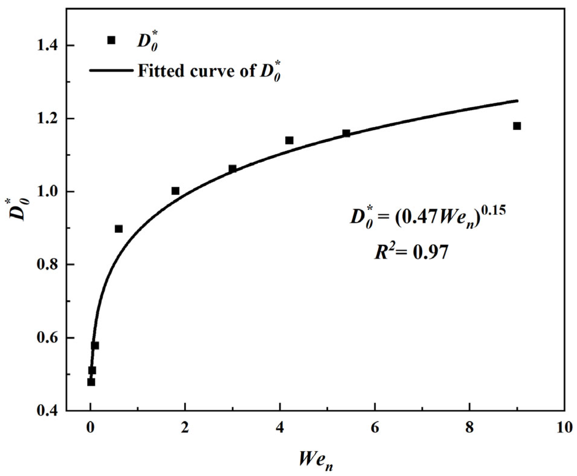
  • Under the operational conditions of this study on a stationary surface, unlike millimeter-sized droplets, micrometer-sized droplets cannot detach from the micro-pillar surface in either the Cassie or Wenzel states, achieving surface detachment only in the partial penetration state. Based on numerical simulation results, a dimensionless maximum spreading diameter formula for droplets impacting stationary micro-pillar surfaces is obtained, which can be expressed as
    D 0 * = ( 0 . 47 W e n ) 0 . 15 .
  • In the process of droplets impacting horizontally moving micro-pillar structured surfaces, significant rolling phenomena occur when droplets are in the Cassie state, which leads to an increase in viscous dissipation and forms a competitive mechanism with the asymmetric spreading–retraction process of the droplets. This compromise effect influences the contact time and velocity restitution coefficient of the droplets. Moreover, the changes in contact time and velocity restitution coefficient exhibit distinct two-stage characteristics, providing new insights into understanding the dynamic behavior of droplets on microstructured surfaces.
  • Through systematic parameter studies, it can be concluded that when micrometer-sized droplets impact horizontally moving micro-pillar structured surfaces, the dimensionless maximum spreading diameter is linearly proportional to Wet. Based on extensive numerical simulation data, a new correlation is fitted as
    D max * = D 0 * + 0.014 W e t W e n 0.45 .
    This model provides a theoretical basis for predicting the dynamic behavior of micrometer-sized droplets on microstructured surfaces.

Author Contributions

Conceptualization, H.Z. and M.W.; methodology, H.Z. and F.J.; software, H.Z.; validation, H.Z., F.J., and M.W.; formal analysis, F.J.; investigation, M.W.; resources, M.W.; data curation, F.J.; writing—original draft preparation, H.Z.; writing—review and editing, M.W.; visualization, H.Z. and F.J.; supervision, M.W.; project administration, M.W.; funding acquisition, M.W. All authors have read and agreed to the published version of the manuscript.

Funding

This research was funded by the National Natural Science Foundation of China (Grant No. 52176080) and Natural Science Foundation of Shandong Province, China (Grant Nos. ZR2019BEE012, ZR2022ME003, and ZR2023ME187).

Institutional Review Board Statement

Not applicable.

Informed Consent Statement

Not applicable.

Data Availability Statement

The data will be made available upon request.

Conflicts of Interest

The authors declare no conflicts of interest.

References

  1. Wang, X.; Xu, B.; Guo, S.; Zhao, Y.; Chen, Z. Droplet impacting dynamics: Recent progress and future aspects. Adv. Colloid Interface Sci. 2023, 317, 102919. [Google Scholar] [CrossRef] [PubMed]
  2. Wang, D.; Sun, Q.; Hokkanen, M.J.; Zhang, C.; Lin, F.; Liu, Q.; Zhu, S.; Zhou, T.; Chang, Q.; He, B.; et al. Design of robust superhydrophobic surfaces. Nature 2020, 582, 55–59. [Google Scholar] [CrossRef] [PubMed]
  3. Breitenbach, J.; Roisman, I.V.; Tropea, C. From drop impact physics to spray cooling models: A critical review. Exp. Fluids 2018, 59, 55. [Google Scholar] [CrossRef]
  4. Cao, L.; Jones, A.K.; Sikka, V.K.; Wu, J.; Gao, D. Anti-Icing Superhydrophobic Coatings. Langmuir 2009, 25, 12444–12448. [Google Scholar] [CrossRef]
  5. Sirringhaus, H.; Kawase, T.; Friend, R.H.; Shimoda, T.; Inbasekaran, M.; Wu, W.; Woo, E.P. High-resolution inkjet printing of all-polymer transistor circuits. Science 2000, 290, 2123–2126. [Google Scholar] [CrossRef]
  6. Yang, C.; Yuan, Y.J. Investigation on the mechanism of nitrogen plasma modified PDMS bonding with SU-8. Appl. Surf. Sci. 2016, 364, 815–821. [Google Scholar] [CrossRef]
  7. Mateo, J.N.; Kulkarni, S.S.; Das, L.; Bandyopadhyay, S.; Tepper, G.C.; Wynne, K.J.; Bandyopadhyay, S. Wetting behavior of polymer coated nanoporous anodic alumina films: Transition from super-hydrophilicity to super-hydrophobicity. Nanotechnology 2011, 22, 35703. [Google Scholar] [CrossRef]
  8. Sun, M.; Li, X.; Ding, B.; Yu, J.; Sun, G. Mechanical and wettable behavior of polyacrylonitrile reinforced fibrous polystyrene mats. J. Colloid Interface Sci. 2010, 347, 147–152. [Google Scholar] [CrossRef]
  9. Ong, Q.K.; Sokolov, I. Attachment of nanoparticles to the AFM tips for direct measurements of interaction between a single nanoparticle and surfaces. J. Colloid Interface Sci. 2007, 310, 385–390. [Google Scholar] [CrossRef]
  10. Chou, S.Y.; Keimel, C.; Gu, J. Ultrafast and direct imprint of nanostructures in silicon. Nature 2002, 417, 835–837. [Google Scholar] [CrossRef]
  11. Song, J.; Gao, M.; Zhao, C.; Lu, Y.; Huang, L.; Liu, X.; Carmalt, C.J.; Deng, X.; Parkin, I.P. Large-Area Fabrication of Droplet Pancake Bouncing Surface and Control of Bouncing State. ACS Nano 2017, 11, 9259–9267. [Google Scholar] [CrossRef] [PubMed]
  12. Quan, Y.; Zhang, L. Numerical and Analytical Study of The Impinging and Bouncing Phenomena of Droplets on Superhydrophobic Surfaces with Microtextured Structures. Langmuir 2014, 30, 11640–11649. [Google Scholar] [CrossRef] [PubMed]
  13. Liu, Y.; Moevius, L.; Xu, X.; Qian, T.; Yeomans, J.M.; Wang, Z. Pancake bouncing on superhydrophobic surfaces. Nat. Phys. 2014, 10, 515–519. [Google Scholar] [CrossRef] [PubMed]
  14. Rothstein, J.P. Slip on Superhydrophobic Surfaces. Annu. Rev. Fluid Mech. 2010, 42, 89–109. [Google Scholar] [CrossRef]
  15. Ukiwe, C.; Kwok, D.Y. On the Maximum Spreading Diameter of Impacting Droplets on Well-Prepared Solid Surfaces. Langmuir 2005, 21, 666–673. [Google Scholar] [CrossRef]
  16. Rioboo, R.; Voué, M.; Vaillant, A.; De Coninck, J. Drop impact on porous superhydrophobic polymer surfaces. Langmuir ACS J. Surf. Colloids 2008, 24, 14074–14077. [Google Scholar] [CrossRef]
  17. Wang, Z.; Lopez, C.; Hirsa, A.; Koratkar, N. Impact dynamics and rebound of water droplets on superhydrophobic carbon nanotube arrays. Appl. Phys. Lett. 2007, 91, 23105. [Google Scholar] [CrossRef]
  18. Kwon, D.H.; Huh, H.K.; Lee, S.J. Wetting state and maximum spreading factor of microdroplets impacting on superhydrophobic textured surfaces with anisotropic arrays of pillars. Exp. Fluids 2013, 54, 1576. [Google Scholar] [CrossRef]
  19. Wang, Y.; Chen, S. Droplets impact on textured surfaces: Mesoscopic simulation of spreading dynamics. Appl. Surf. Sci. 2015, 327, 159–167. [Google Scholar] [CrossRef]
  20. Zhang, R.; Hao, P.; He, F. Drop Impact on Oblique Superhydrophobic Surfaces with Two-Tier Roughness. Langmuir 2017, 33, 3556–3567. [Google Scholar] [CrossRef]
  21. Liu, Y.; Whyman, G.; Bormashenko, E.; Hao, C.; Wang, Z. Controlling drop bouncing using surfaces with gradient features. Appl. Phys. Lett. 2015, 107, 51604. [Google Scholar] [CrossRef]
  22. Lv, C.; Hao, P.; Zhang, X.; He, F. Drop impact upon superhydrophobic surfaces with regular and hierarchical roughness. Appl. Phys. Lett. 2016, 108, 141602. [Google Scholar] [CrossRef]
  23. Zhang, R.; Hao, P.; Zhang, X.; Niu, F.; He, F. Tunable Droplet Breakup Dynamics on Micropillared Superhydrophobic Surfaces. Langmuir 2018, 34, 7942–7950. [Google Scholar] [CrossRef] [PubMed]
  24. Gao, S.; Liao, Q.; Liu, W.; Liu, Z. Nanodroplets Impact on Rough Surfaces: A Simulation and Theoretical Study. Langmuir ACS J. Surf. Colloids 2018, 34, 5910–5917. [Google Scholar] [CrossRef]
  25. Wang, L.; Zhou, A.; Zhou, J.; Chen, L.; Yu, Y. Droplet impact on pillar-arrayed non-wetting surfaces. Soft Matter 2021, 17, 5932–5940. [Google Scholar] [CrossRef]
  26. Andrew, M.; Liu, Y.; Yeomans, J.M. Variation of the Contact Time of Droplets Bouncing on Cylindrical Ridges with Ridge Size. Langmuir ACS J. Surf. Colloids 2017, 33, 7583–7587. [Google Scholar] [CrossRef]
  27. Gauthier, A.; Symon, S.; Clanet, C.; Quéré, D. Water impacting on superhydrophobic macrotextures. Nat. Commun. 2015, 6, 8001. [Google Scholar] [CrossRef]
  28. Bird, J.C.; Dhiman, R.; Kwon, H.; Varanasi, K.K. Reducing the contact time of a bouncing drop. Nature 2013, 503, 385–388. [Google Scholar] [CrossRef]
  29. Liu, C.; Liu, Q.; Lin, Z. Dynamical behavior of droplets transiently impacting on superhydrophobic microstructures. Phys. Fluids 2020, 32, 103304. [Google Scholar] [CrossRef]
  30. Lin, D.; Wang, L.; Wang, X.; Yan, W. Reduction in the contact time of impacting droplets by decorating a rectangular ridge on superhydrophobic surfaces. Int. J. Heat Mass Transf. 2019, 132, 1105–1115. [Google Scholar] [CrossRef]
  31. Zhang, X.; Zhu, Z.; Zhang, C.; Yang, C. Reduced contact time of a droplet impacting on a moving superhydrophobic surface. Appl. Phys. Lett. 2020, 117, 151602. [Google Scholar] [CrossRef]
  32. Hao, J.; Green, S.I. Splash threshold of a droplet impacting a moving substrate. Phys. Fluids 2017, 29, 12103. [Google Scholar] [CrossRef]
  33. Chen, R.H.; Wang, H.W. Effects of tangential speed on low-normal-speed liquid drop impact on a non-wettable solid surface. Exp. Fluids 2005, 39, 754–760. [Google Scholar] [CrossRef]
  34. Almohammadi, H.; Amirfazli, A. Understanding the drop impact on moving hydrophilic and hydrophobic surfaces. Soft Matter 2017, 13, 2040–2053. [Google Scholar] [CrossRef]
  35. Buksh, S.; Almohammadi, H.; Marengo, M.; Amirfazli, A. Spreading of low-viscous liquids on a stationary and a moving surface. Exp. Fluids 2019, 60, 76. [Google Scholar] [CrossRef]
  36. Raman, K.A. Normal and oblique droplet impingement dynamics on moving dry walls. Phys. Rev. E 2019, 99, 53108. [Google Scholar] [CrossRef]
  37. Zhan, H.; Lu, C.; Liu, C.; Wang, Z.; Lv, C.; Liu, Y. Horizontal Motion of a Superhydrophobic Substrate Affects the Drop Bouncing Dynamics. Phys. Rev. Lett. 2021, 126, 234503. [Google Scholar] [CrossRef]
  38. Cheng, Y.; Lu, S.; Xu, W.; Wen, H.; Wang, J. Fabrication of superhydrophobic Au–Zn alloy surface on a zinc substrate for roll-down, self-cleaning and anti-corrosion properties. J. Mater. Chem. A 2015, 3, 16774–16784. [Google Scholar] [CrossRef]
  39. Boreyko, J.B.; Chen, C. Restoring Superhydrophobicity of Lotus Leaves with Vibration-Induced Dewetting. Phys. Rev. Lett. 2009, 103, 174502. [Google Scholar] [CrossRef]
  40. Wei, W.; Ji, C.; Fangye, L.; Zou, J.; Dorbolo, S. Water drops bouncing off vertically vibrating textured surfaces. J. Fluid Mech. 2019, 876, 1041–1051. [Google Scholar]
  41. Huber, R.A.; Campbell, M.; Doughramaji, N.; Derby, M.M. Vibration-enhanced droplet motion modes: Simulations of rocking, ratcheting with breakup, and ejection. J. Fluids Eng. 2019, 141, 071105. [Google Scholar]
  42. Pillai, R.; Borg, M.K.; Reese, J.M. Dynamics of Nanodroplets on Vibrating Surfaces. Langmuir ACS J. Surf. Colloids 2018, 34, 11898–11904. [Google Scholar] [CrossRef]
  43. Raman, K.A.; Jaiman, R.K.; Sui, Y.; Lee, T.; Low, H. Rebound suppression of a droplet impacting on an oscillating horizontal surface. Phys. Rev. E 2016, 94, 23108. [Google Scholar] [CrossRef]
  44. Mettu, S.; Chaudhury, M.K. Motion of Drops on a Surface Induced by Thermal Gradient and Vibration. Langmuir 2008, 24, 10833–10837. [Google Scholar] [CrossRef] [PubMed]
  45. Moradi, M.; Rahimian, M.H.; Chini, S.F. Numerical simulation of droplet impact on vibrating low-adhesion surfaces. Phys. Fluids 2020, 32, 62110. [Google Scholar] [CrossRef]
  46. Hee Kwon, D.; Joon Lee, S. Impact and wetting behaviors of impinging microdroplets on superhydrophobic textured surfaces. Appl. Phys. Lett. 2012, 100, 171601. [Google Scholar] [CrossRef]
  47. Sussman, M.; Puckett, E.G. A Coupled Level Set and Volume-of-Fluid Method for Computing 3D and Axisymmetric Incompressible Two-Phase Flows. J. Comput. Phys. 2000, 162, 301–337. [Google Scholar] [CrossRef]
  48. Hirt, C.W.; Nichols, B.D. Volume of fluid (VOF) method for the dynamics of free boundaries. J. Comput. Phys. 1981, 39, 201–225. [Google Scholar] [CrossRef]
  49. Osher, S.; Sethian, J.A. Fronts propagating with curvature-dependent speed: Algorithms based on Hamilton-Jacobi formulations. J. Comput. Phys. 1988, 79, 12–49. [Google Scholar] [CrossRef]
  50. Dai, X.; Zhang, W.; Zhang, J.; Xin, G.; Wang, X. Numerical study of droplet impact on superhydrophobic vibrating surfaces with microstructures. Case Stud. Therm. Eng. 2022, 30, 101732. [Google Scholar] [CrossRef]
  51. Field, J.E. ELSI conference: Invited lecture: Liquid impact: Theory, experiment, applications. Wear 1999, 233–235, 1–12. [Google Scholar] [CrossRef]
  52. Deng, T.; Varanasi, K.K.; Hsu, M.; Bhate, N.; Keimel, C.; Stein, J.; Blohm, M. Nonwetting of impinging droplets on textured surfaces. Appl. Phys. Lett. 2009, 94, 133109. [Google Scholar] [CrossRef]
  53. Richard, D. Contact time of a bouncing drop. Nature 2002, 417, 811. [Google Scholar]
  54. Qian, L.; Huo, B.; Chen, Z.; Li, E.; Ding, H. Droplet bouncing on moving superhydrophobic groove surfaces. Int. J. Multiph. Flow 2023, 165, 104454. [Google Scholar] [CrossRef]
  55. Aboud, D.G.K.; Kietzig, A. Influence of Microstructure Topography on the Oblique Impact Dynamics of Drops on Superhydrophobic Surfaces. Langmuir 2021, 37, 4678–4689. [Google Scholar] [CrossRef]
  56. Shu, Y.; Hu, Z.; Feng, Y.; Wu, X.; Dong, Z.; Chu, F. Prince Rupert’s Drop bouncing on high-speed moving superhydrophobic surfaces. Int. Commun. Heat Mass Transf. 2023, 148, 107049. [Google Scholar] [CrossRef]
  57. Xia, L.; Yang, Z.; Chen, F.; Liu, T.; Tian, Y.; Zhang, D. Droplet impacting on pillared hydrophobic surfaces with different solid fractions. J. Colloid Interface Sci. 2024, 658, 61–73. [Google Scholar] [CrossRef]
  58. Biance, A.; Chevy, F.; Clanet, C.; Lagubeau, G.; Quéré, D. On the elasticity of an inertial liquid shock. J. Fluid Mech. 2006, 554, 47–66. [Google Scholar]
  59. Aria, A.I.; Gharib, M. Physicochemical Characteristics and Droplet Impact Dynamics of Superhydrophobic Carbon Nanotube Arrays. Langmuir 2014, 30, 6780–6790. [Google Scholar] [CrossRef]
  60. Aboud, D.; Kietzig, A. On the Oblique Impact Dynamics of Drops on Superhydrophobic Surfaces. Part II: Restitution Coefficient and Contact Time. Langmuir 2018, 34, 9889–9896. [Google Scholar] [CrossRef]
  61. Hu, A.; Liu, D. 3D simulation of micro droplet impact on the structured superhydrophobic surface. Int. J. Multiph. Flow 2022, 147, 103887. [Google Scholar] [CrossRef]
  62. Liu, Y.; Andrew, M.; Li, J.; Yeomans, J.M.; Wang, Z. Symmetry breaking in drop bouncing on curved surfaces. Nat. Commun. 2015, 6, 10034. [Google Scholar] [CrossRef]
Figure 1. Physical model and geometric parameters used in this study.
Applsci 15 03188 g001
Figure 2. Schematic of parameter definitions for droplet impact on a micro-pillar surface.
Applsci 15 03188 g002
Figure 3. Validation of droplet shape evolution during the spreading and recoiling phases on micro-pillar surfaces compared to the results in the literature. (a) The 3D simulation results from this study; (b) results of Dai et al. [50]; (c) results of Quan and Zhang [12]; and (d) results of Kwon and Lee [46].
Applsci 15 03188 g003
Figure 4. Mesh independence verification with the contact area during the droplet impact process.
Applsci 15 03188 g004
Figure 5. Dynamic behavior of a droplet impacting on a stationary surface with a micro-pillar structure. (a) Cassie state, Wen = 0.04; (b) partial penetration state, Wen = 3; (c) Wenzel state, Wen = 9.
Applsci 15 03188 g005
Figure 6. Variations in different parameters with the impact velocity on a stationary micro-pillar surface. (a) Dimensionless penetration depth; (b) dimensionless contact time; (c) dimensionless maximum spreading diameter; (d) velocity restitution coefficient. The blue area is the Cassie state, the green area is the partial penetration state, and the red area is the Wenzel state.
Applsci 15 03188 g006
Figure 7. Variation in the maximum spreading diameter of a droplet impacting on a stationary wall with respect to Wen and the fitted correlation.
Applsci 15 03188 g007
Figure 8. Velocity distribution on the x-y cross-section during droplet impact on a moving surface (Wen = 1.8). (a) Wet = 0.8; (b) Wet = 6.4.
Applsci 15 03188 g008
Figure 9. Droplet contour lines at different times in the cases of Wen = 1.8 and Wet = 6.4.
Applsci 15 03188 g009
Figure 10. Pressure distribution on the x-y cross-section inside the droplet (t* = 1.62, z = 0, Wen = 1.8). (a) Wet = 0; (b) Wet = 6.4.
Applsci 15 03188 g010
Figure 11. Velocity restitution coefficients for different cases. The pink region indicates a rapid decrease in εn and the light blue region indicates fluctuating εn.
Applsci 15 03188 g011
Figure 12. Variations in dissipated energy and kinetic energy during droplet impact on a moving surface with Wet = 4.
Applsci 15 03188 g012
Figure 13. Variation in the dimensionless maximum spreading diameter of droplets with Wet and Wen. (a) Cases with Wen = 0.6–4.2; (b) prediction case with Wen = 5.4.
Applsci 15 03188 g013
Figure 14. Variation in the droplet contact time with Wen on horizontal moving micro-pillar structured surfaces with different Wets.
Applsci 15 03188 g014
Disclaimer/Publisher’s Note: The statements, opinions and data contained in all publications are solely those of the individual author(s) and contributor(s) and not of MDPI and/or the editor(s). MDPI and/or the editor(s) disclaim responsibility for any injury to people or property resulting from any ideas, methods, instructions or products referred to in the content.

