Abstract
Surface nanopatterning induced by ion beam irradiation allows for the creation of patterns on large areas of a wide variety of materials. However, surface composition plays a crucial role in the process. In this study, we investigate the bombardment of a metallic alloy, specifically an Au-Cu system with different compositions, discussing differences in the formation of patterns compared to pure materials. Mixtures with compositions ranging from 35 to 65 at.% Cu exhibit a dampening effect on ripple height and depth. At intermediate angles of incidence, horizontal displacement is minimized and sputtering maximized; conversely, at grazing angles, sputtering is minimized and horizontal displacement becomes dependent on material mobility. It is, therefore, evident that sputtering determines the patterning for intermediate angles. However, an analysis of the redistribution factor as a function of the angle of incidence shows that the weight of the redistribution is much lower than that of sputtering in alloys of similar composition at grazing angles due to the amorphization process. This point is confirmed by the data on displaced atoms obtained from the relocation cross-sections.
1. Introduction
Ion beam irradiation enables pattern formation to be induced in a wide range of materials, such as metals [1], semiconductors, oxides, ionic crystals, and polymers. The applications of nanopatterning induced by ion beam irradiation are varied and affect several areas of knowledge, such as photovoltaics, magnetism, nanoelectronics, plasmonics, sensing, and biomaterials [2]. This article addresses the differences found in the appearance of patterns when composition effects are present. Nanoscale patterns on surfaces caused by ion beam irradiation are broadly driven by the competition between erosion processes and diffusion processes [3]. Bradley and Harper [4] used a linear model of Sigmund’s sputtering theory and Mullins’ diffusion theory to develop an initial model of the phenomenon. Cuerno and Barabasi [5] used a nonlinear model based on previous sputtering theory to refine the model. These theories are all for amorphous materials; however, experiments with metals show that surface crystallography plays an important role in pattern formation [6]. Using ideas similar to Carter et al. [7], molecular dynamics (MD) has shown that the atomic displacement induced by the ion can also be the cause of the phenomenon [8,9] in low-energy bombardment. Based on this new effect, new formalisms have been developed that explain the formation of patterns [10]. However, despite these additional physical mechanisms that have been taken into account and some others that have not been mentioned in this work (surface viscous flow, stress effects, ion implantation, etc.) [11,12,13], a complete understanding of the surface patterning induced by ion beam irradiation has not been achieved.
The main conclusion from the experimental findings is that patterning is not a universal process but depends on the ion/target combination [2]. In fact, we have not found in the recent literature any experimental work addressing this issue on the materials analyzed in this work. The first attempt to model a binary compound was made by Shenoy et al. [14]. These authors obtained surface compositional variations. Later, Bradley and Shipman [15] developed a two-field model to explain pattern formation in compound materials, patterns such as those obtained experimentally by Fakso et al. [16] on GaSb. In their lastest study on the subject [17], they introduced into the previous model an ion-induced diffusion current term similar to that introduced by Carter et al. [7].
Recently, it has become possible to directly observe the formation of patterns using MD on amorphous silicon surfaces under very low incident energies of 30 eV [18,19]. In previous works [20,21], we studied pattern formation in pure metallic systems and concluded that, at intermediate angles, the process is primarily governed by redistribution, while at grazing angles, it is dominated by sputtering. When the surface consists of different atomic species, local differences emerge in processes such as sputtering and surface displacement due to the distinct components, which, in turn, influence pattern formation. These effects could even induce phase separations within surface patterns [2]. Furthermore, the surface morphology could be altered depending on the composition. Not all particles in the solid have the same mobility or the same erosion tendency. In summary, this work addresses two objectives. On the one hand, the current literature does not clarify what processes lead to the formation of surface patterns in alloys; on the other, the structural and morphological differences between alloy patterns and patterns in pure metals are unclear.
In the case of metals, the crystalline structure remains intact during the process. The diffusive regime, which depends on crystal symmetry, plays a secondary role compared to the erosive regime under conditions of high ion fluence and/or low surface temperature [22]. In this way, the results are determined by the erosive phase.
In this work, we investigate the influence of both processes, namely sputtering and redistribution, on the formation of surface patterns during cluster bombardment of Au-Cu alloys. The molecular dynamics code used in this work has been previously used in other works [20,21] and is of our own development. We focus only on clusters of very few atoms: Ar6 clusters, each with an energy of 250 eV/atom. To analyze the effects of the components, we will bombard a face-centered cubic (fcc) Au-Cu surface with the following composition (at.% Cu): 0, 20, 35, 50, 65, 80, and 100. Each surface will be bombarded under different angles of incidence (between 30–70°) to analyze the angular dependence of the quantities considered.
Initially, we will analyze the resulting atomic surface morphology after bombardment. We will relate this configuration to the sputtering yield curves and collision-induced displacements. Next, we discuss the angular dependence of these quantities for an alloy compared to a pure system. Finally, we draw conclusions using the relocation cross-sections.
2. Model
In this study, an Au-Cu alloy surface has been bombarded in the form of an fcc lattice oriented in the <110> direction. The crystallographic axis <001> aligns with the y-axis, while the two <110> directions coincide with the remaining coordinate axes. The number of unit cells of the Au-Cu substrate along the x, y, and z-axes was 56 × 28 × 14. The cell length depended on the composition and was taken from the reference [23]. The x and y-directions extended the crystal using periodic conditions. The initial system before the bombardment can be visualized in other works [20,21]. For the most part, the details of the model are the same as those found in these works.
The substrate was fixed, keeping the three lower layers fixed perpendicular to the z-direction. On top of these, there were five layers that thermally controlled the system using a generalized Langevin equation [24]. These layers absorbed heat to maintain the temperature at 300 K as in other works [20]. The second-moment tight-binding potential in the framework of the Finnis–Sinclair model described the interactions between Au-Cu atoms [25]. At short distances, approximately between 1.7 and 2.0 Å depending on the material, this potential is smoothly coupled to the ZBL potential via a bond function. Ar-Cu and Ar-Au interactions are described by the ZBL potential for any distance.
The bombarded surface is free from all stress. First, a periodic fcc network at 5 K with the desired composition is randomly generated. Subsequently, the system is heated to 300 K by scaling the temperature in six steps and stabilizing the system for 50 ps. In this process, the canonical ensemble is used with an inertia factor associated with temperature (adjustable parameter) equal to Q = 10−36 g cm2. The system is then relaxed at zero pressure for 300 ps in the canonical isobaric ensemble with the associated inertia factor (also adjustable) W = 1019 g [26]. Finally, we remove periodic conditions along the z-axis, fixing the bottom and relaxing the system in the microcanonical ensemble coupled to a thermal bath.
Each substrate–cluster collision lasted 25 ps. This time interval is similar to that used in other works [20,21]. The time step was 0.5 fs for the first 15 ps. The step was then doubled since the collisional processes were less energetic. The system was scaled to 300 K at 20 ps and subsequently relaxed for 5 ps before the next cluster was launched. This ensured similar temperature conditions for each launch. In any case, the system evolves in the microcanonical ensemble coupled to a thermal bath. In each launch, the impact always occurred in the center of the solid in the y-direction, for which the frame of reference was moved. Statistically, the results should be independent of this coordinate.
The launched clusters of six atoms had an octahedral shape (without an atom in the center). This is a fairly common shape, although the results do not depend on this fact, since the impacts always occurred randomly. Clusters were selected instead of atoms to accelerate the surface response and shorten the simulation time. Obviously, it is always possible to choose larger clusters; however, this could interfere with the boundary conditions. However, their influence has been studied in a previous article [20]. The potential that models the interaction in the clusters is the Lennard–Jones [27], taking the interatomic separation that minimizes its energy. The angle of incidence of the clusters varied between 30° and 70° to study their influence on specific parameters.
A total of 336 clusters were launched on the target; that is, the surface was bombarded with approximately 2000 Ar atoms in total, each with 250 eV. Therefore, the influence of the number of implanted Ar atoms is very small. The bombardment simulated a linearly focused ion beam by randomly impacting the x-coordinate of the geometric center of the cluster within a range between −10 and 0 Å. The goal is to significantly reduce the surface response time by exciting a surface ripple. Realistic MD simulations at this energy remain unfeasible. This model has been previously used in other works to draw conclusions about this phenomenon [9,28]. The fluence or number of atoms thrown per unit area will be 2 × 10¹⁶ atoms·cm−2.
The surface morphology can be modified due to two processes. On the one hand, the atoms of the solid can be eroded. The magnitude that characterizes this process is the sputtering yield Y or atoms leaving the solid per incident Ar atom. On the other hand, the atoms of the solid are redistributed on its surface due to the atomic collisions induced by the cluster. To quantify the redistribution, the horizontal displacement of the atoms is calculated [9]:
where Nd is the number of displaced atoms and (xi0, yi0, zi0) and (xi, yi, zi) are the initial and generic positions of atom i of the substrate, respectively. Vertical displacement could also be defined by analogy by changing the x-coordinate to the z-coordinate.
3. Results and Discussion
3.1. Atomic Description
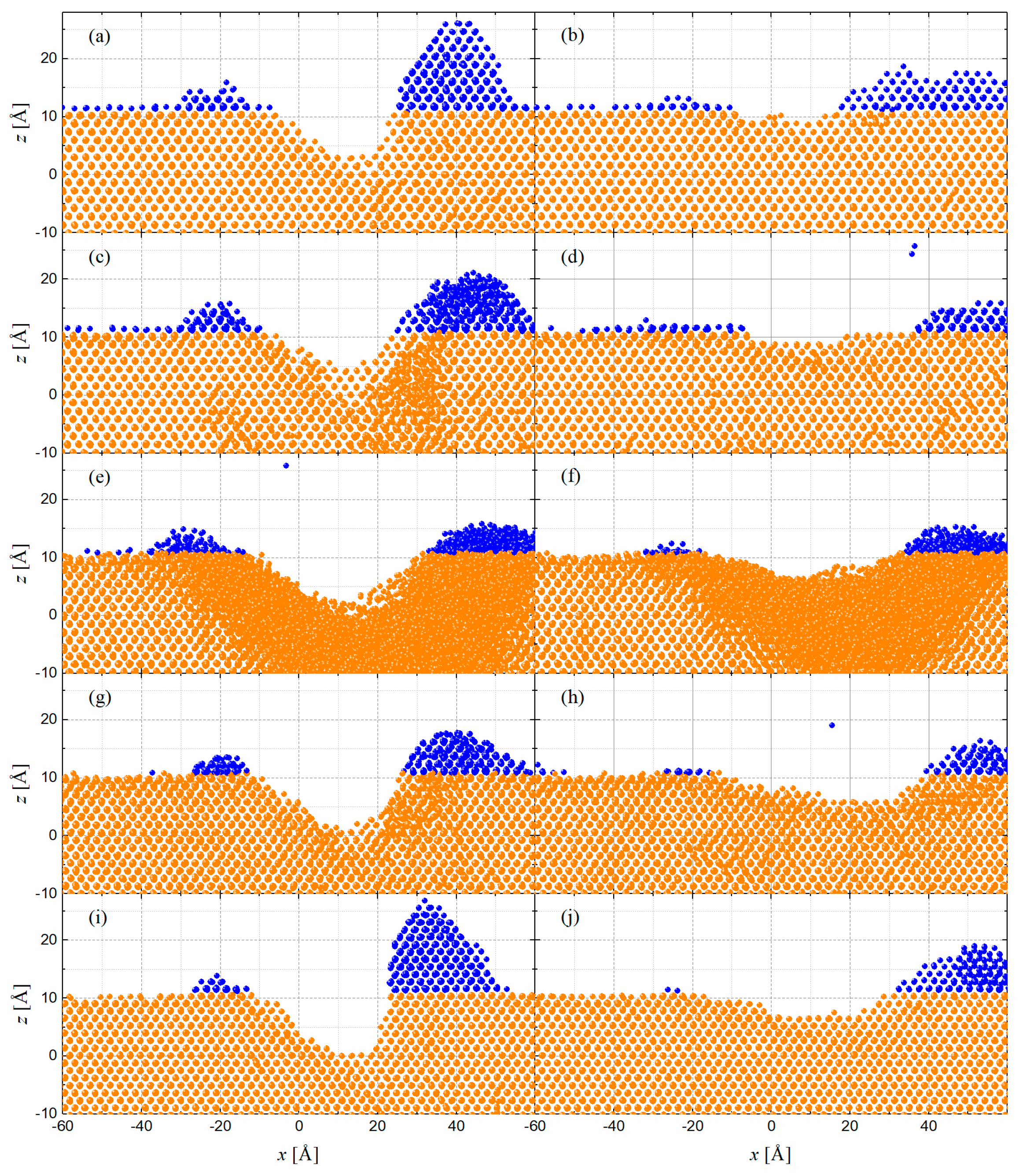
First, we compare the two pure substances, Cu and Au. Cu is a lighter element; therefore, it exhibits greater mobility than Au. In Figure 1 we have shown the results after the bombardments for two angles of incidence: 50° and 70°. Figure 1a,b,i,j show how the mobility of Cu fundamentally affects the horizontal displacement, forming a more extensive wave pulse. The height of the pulse appears similar; however, differences in the vertical displacement are observed, indicating that the number of displaced atoms in the case of Cu is greater.

Figure 1.
xz projections of the system after bombardment with clusters for two angles of incidence: 50° (a,c,e,g,i) and 70° (b,d,f,h,j) and a fluence of 1016 atoms·cm−2. The figures correspond to different surface concentrations (at.% Cu): 0 (a,b), 20 (c,d), 50 (e,f), 80 (g,h), 100 (i,j). The crystallographic viewing direction is <100>. The two surface ridges resulting from the bombardment are shown in blue.
Unlike previous cases, the shape of the ripple is noticeably softened when it comes to an alloy. That is, the wave pulse becomes wider and less tall and deep. The most significant case is the one that corresponds to the surface with the same proportion of atoms (Figure 1e,f). In this case, it is observed how the solid has lost its structure near the impact zone of the clusters; that is, it has undergone an amorphization process. Disorder is introduced by energetic collisions that disrupt the ordered lattice due to local rapid cooling processes and the loss of compositional homogeneity. Instabilities closer to equilibrium, such as localized phase separation, may occur; however, these will be second-order effects [29]. Taking into account this property and the results obtained in other research [28], it seems that the redistribution process is decisive in determining the formation of surface ripples. However, we will soon see that the different quantities involved in the process contradict this statement. If the radial distribution function is analyzed, the maxima are smoothed out, and atoms begin to appear at intermediate distances. The underlying local order is the same, but the structure is lost on a large scale by alteration of local distances. In Figure 1, the structures for concentrations of 35 and 65 at.% Cu have not been represented. The reason is that the wave pulse is very similar in appearance to the case of equal concentration (Figure 1e,f). The only difference is that the amorphization zone is much smaller, especially in the case of 35 at.% Cu, since it does not appear on the side of the groove where the cluster does not hit. This suggests that the greater mobility of Cu induces this phenomenon. In short, although simulation times prevent a detailed statistical study of the results, Figure 1 shows a gradual morphology variation due to concentration changes, confirming the influence of this magnitude.
To obtain information on short-range changes in atomic order after the bombardment, we performed a common neighbor analysis (CNA) [30]. Each pair of bonded atoms (separated less than the first minimum of the radial distribution function) can be assigned three indices (klm). The first index k is the number of neighbors common to both atoms. The second index l is the number of bonds between these common neighbors. The third index m is the number of bonds in the longest continuous chain formed by the l bonds between common neighbors. We took an area surrounding the groove belonging to an Oxz layer and analyzed it by this procedure in the case of the Au substrate bombarded at 50°. We found that 83.3% were bonds (421) characteristic of an fcc lattice and the remaining 12% were bonds (311) characteristic of the contours of an fcc lattice. We repeated the same process for the 50% Au-Cu substrate bombarded at 50° and found considerable differences. The perfect bonds (421) dropped to 17%, which is indicative that the lattice partially destroys its fcc symmetry, and the bonds (311) rise to 18%. We could observe the appearance of other bonds, such as (433) pairs with a frequency of 18% and (544) pairs with 6.5%. These structures are characteristic of supercooled liquids and can be seen as fragments of local icosahedrons [31]. The local icosahedral structure (555) also appeared with a frequency of 6.5%. The (211) pairs that can also be seen as defects of the icosahedral structure were also found at 6.3% [32]. We should also note that the hcp order, which is characteristic of twining planes and represented by the (422) bond, was present with a frequency of 7.2%. Finally, (200) pairs appeared at 5.7% and (322) pairs at 10% and reflect the obvious fact that the coordination of the atoms varies strongly in the amorphous cascade. These bonds are characteristic of short-range atomic arrangements that enable a high packing density of atoms without forming well-ordered, periodic structures.
3.2. Sputter Yield and Displacement
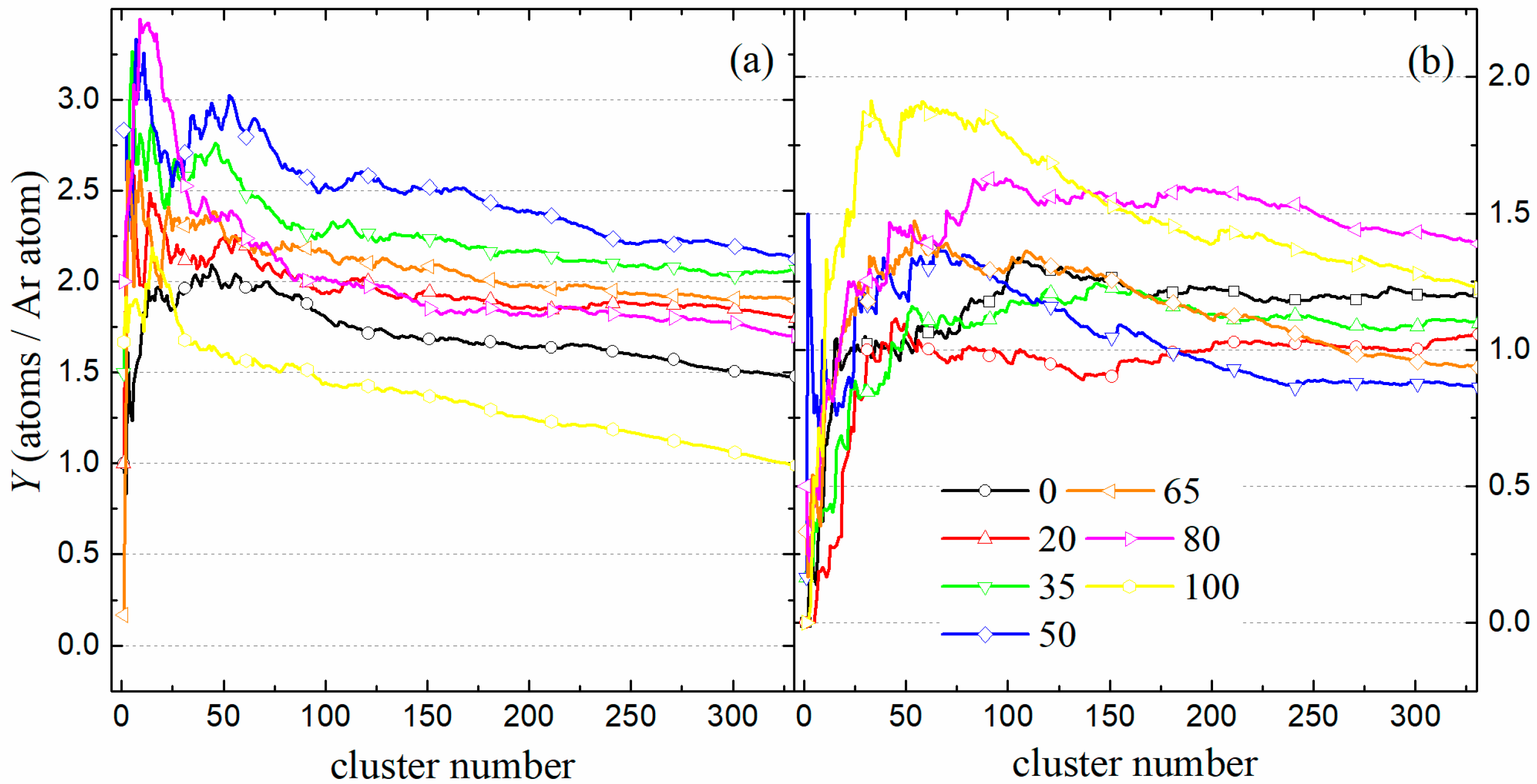
First, we will analyze the magnitudes most closely related to the formation of surface ripples. Figure 2 shows the sputtering yield obtained for the different systems for the two angles of incidence. For intermediate angles (Figure 2a), the sputtering is lower for pure substances and higher for alloys of similar concentration. However, this trend reverses when the angle is grazing (Figure 2b), then the sputtering is lower for alloys of similar concentration. This result highlights a distinction in the mechanisms at play between pure metals and alloys.

Figure 2.
Sputter yields for bombardment with Ar6 clusters and different angles of incidence: (a) 50° and (b) 70° as a function of cluster number. In both cases, 2000 Ar atoms are launched onto the solid at the end of the process.
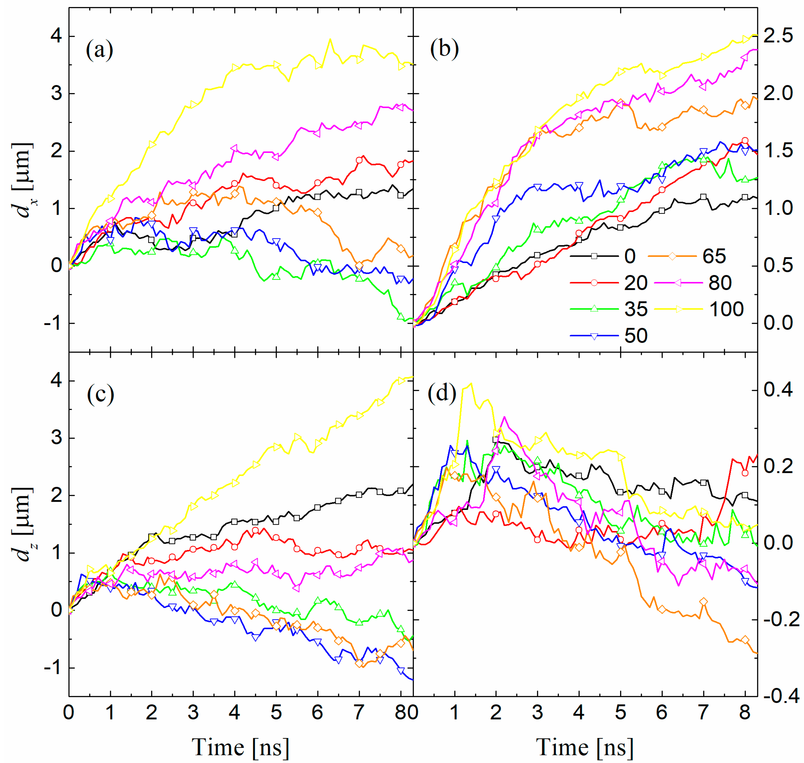
Figure 3 represents the horizontal and vertical displacements for angles of incidence of 50° and 70°. Horizontal and vertical displacements have the opposite behavior to sputtering for intermediate angles. That is, for alloys of similar concentration, the displacement is lower, while for pure substances, it is greater (Figure 3a,c). This result is more visible in the case of Cu, the lightest species. This sputtering and displacement behavior points to the former as the fundamental mechanism in alloys for intermediate angles. For grazing angles, the issue is more complicated, since the horizontal displacement curves are ordered according to the Cu concentration (Figure 3b); therefore, the mobility of Cu is what determines this displacement. The vertical displacement curves are also minimal for alloys of equal concentration (Figure 3d). Finally, we must remember that the sputtering curves are minimal for alloys of this type. This fact leads us to believe that there is no clear dominant factor in pattern formation since no maximum occurs in alloys, either in sputtering or in redistribution. Recall that in pure metals, the predominant process for intermediate angles was redistribution, while for grazing angles, the predominant process was sputtering [20,21].
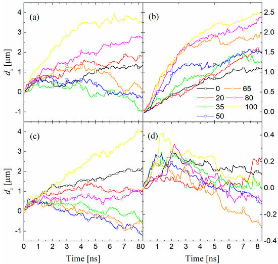
Figure 3.
Horizontal dx (a,b) and vertical dz (c,d) displacements for bombardment of a surface with different concentrations (at.% Cu): 0, 20, 35, 50, 65, 80, and 100 and different angles of incidence: (a,c) 50° and (b,d) 70° as a function of time.
3.3. Volume Exchange
In the following, we analyze the process of volume exchange during atomic bombardment. In principle, we disregard the volume of the Ar atoms we implant as being small compared to the rest. In general, any atom that occupies a volume in the groove can end up sputtered, redistributed, or placed on the surface. Therefore, we can affirm that: , where Vad is the volume occupied by the atoms in the ridges, Vsp is the volume of the eroded atoms, and Vrd is the redistributed volume of negative value because the atoms of the solid generally fill the groove.
The redistribution of atoms is associated with the formation of ridges and the internal rearrangement of atoms, that is, . This causes the groove volume to be created from redistributed and unredistributed atoms [28].
We could define a redistribution factor as shown in the following expression:
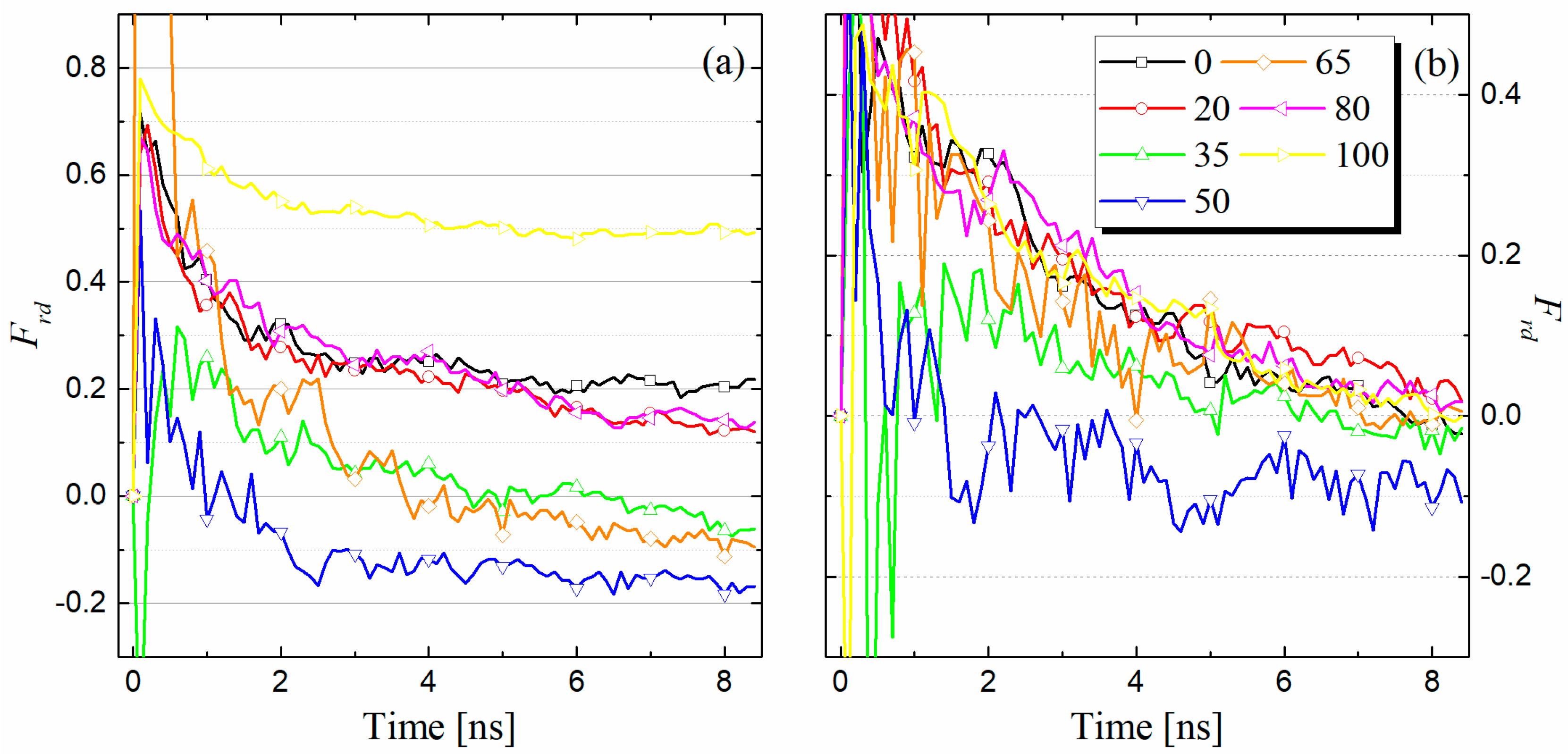
At this point, we must remember that a redistribution factor greater than 0.2 indicates a higher redistribution weight [21]. In Figure 4, we represent this factor for surfaces of different concentrations bombarded at two angles of incidence as a function of time. Figure 4a corresponding to intermediate angles (50°) is more interesting. This figure shows a prominent redistribution factor for pure substances. According to the value indicated previously, the effect of redistribution predominates in these materials. However, for alloys of similar concentration, this factor becomes small and even negative, which means that sputtering prevails. A negative volume means that the volume located above the surface at the ridges becomes smaller than the volume that recedes to fill the groove. This fact confirms the maximum found in the sputtering yield and the minimum in the displacements. It should also be noted that the redistribution factor of light-species metals is much greater than that of heavy-species metals. This links the effect to the greater mobility of Cu.

Figure 4.
Redistribution factor Frd for different angles of incidence: (a) 50° and (b) 70° and surfaces of varying compositions (at.% Cu): 0, 20, 35, 50, 65, 80, and 100 as a function of time.
For their part, the curves for grazing angles are all very similar (Figure 4b), except for the equal concentration curve, which shows significantly negative values. According to this model, sputtering is clearly the predominant factor in all cases. This result corrects previous findings that attributed the predominance of redistribution effects to amorphous solids [28]; those findings are likely specific to the material studied, amorphous silicon.
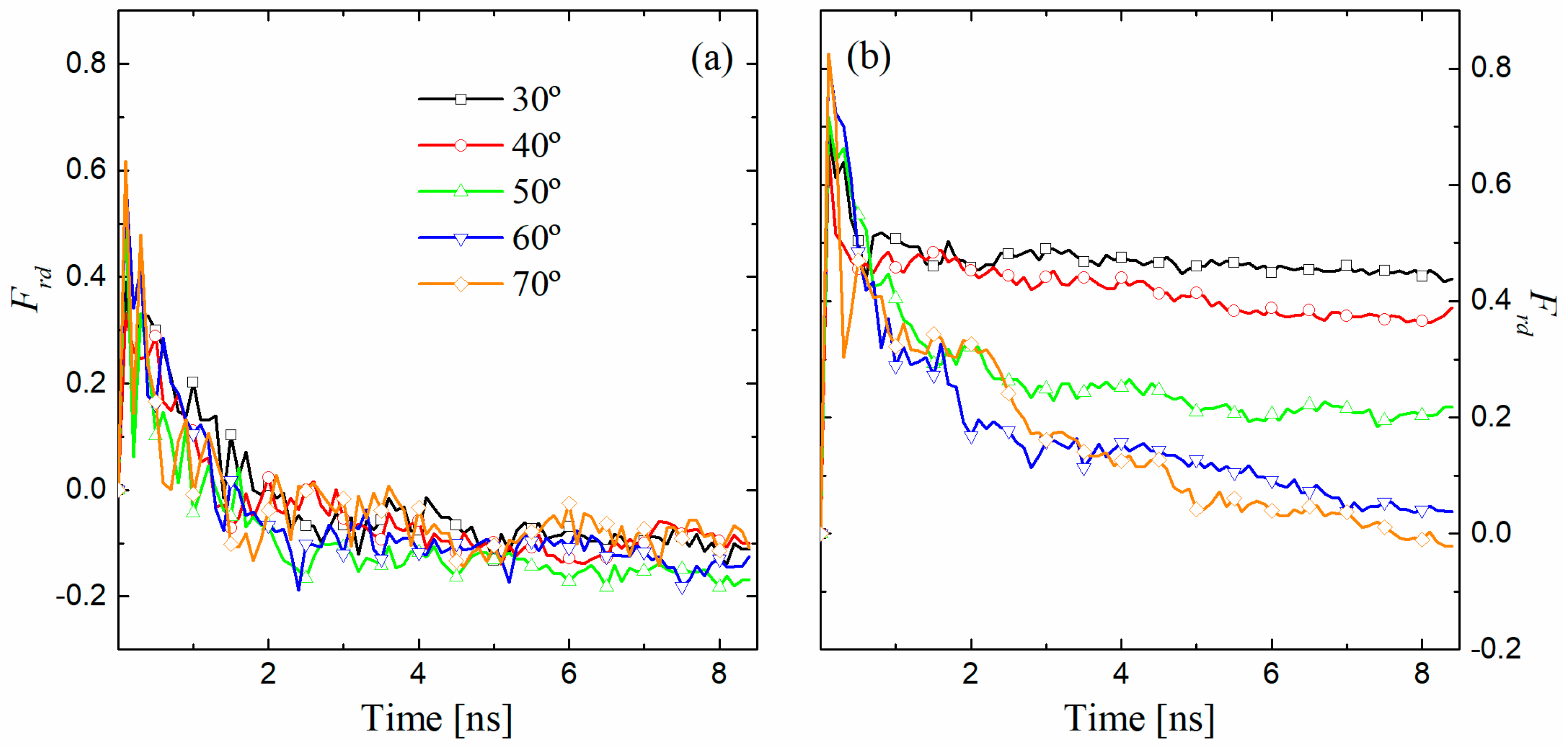
We should study the angular differences in the redistribution factor with the concentration of alloys. To do this, in Figure 5, we compare this factor in the bombardment of two surfaces: one of pure Au and the other of Au-Cu at the same concentration. In the latter case (Figure 5a), the curves indicate that sputtering is the dominant effect at all studied angles, as the factor remains below 0.2. In fact, the volumes of the ridges are very similar for all angles, with the volume of the groove differing somewhat more. In any case, the redistributed volume gives negative volumes because of the small size of the ridges. These dimensions of the ridges are probably induced by the limited vertical travel of the atoms due to the lack of crystallinity of the solid. This is evident when comparing the average displacements in the z-direction: 2.5 Å for Au and −1 Å for 50% Au-Cu, both bombarded at 50°; 0.24 Å for Au and −0.15 Å for 50% Au-Cu, both bombarded at 70°. The case of the pure Au substrate (Figure 5b) confirms previous findings: at intermediate angles, redistribution predominates, while at grazing angles, sputtering is the dominant effect [20,21]. Undoubtedly, the defects generated by irradiation enhance the local mobility of atoms. In this sense, local displacements would be larger in amorphous solids. However, the effect we are concerned with is not local, but long-range.
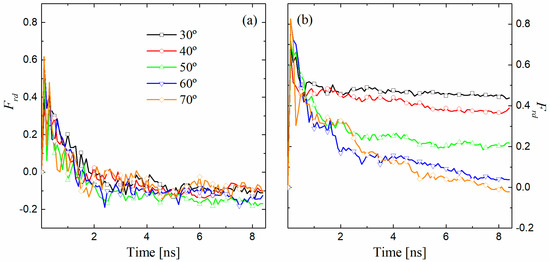
Figure 5.
Redistribution factor Frd for two surfaces of two compositions (at.% Cu): (a) 50 and (b) 0 and different angles of incidence: 30°, 40°, 50°, 60°, and 70° as a function of time.
It is important to highlight some differences between the sputtering curves of previous systems. In the case of Au, the sputtering is minimal for an incidence close to normal (30–40°). This leads to a higher redistribution factor for intermediate angles. The horizontal displacement curves indicate that, for 50% Au-Cu, the maximum displacement occurs at an angle of 70°. In fact, the redistribution factor, without reaching values that make it significant against sputtering, is the highest for this angle (Figure 5a).
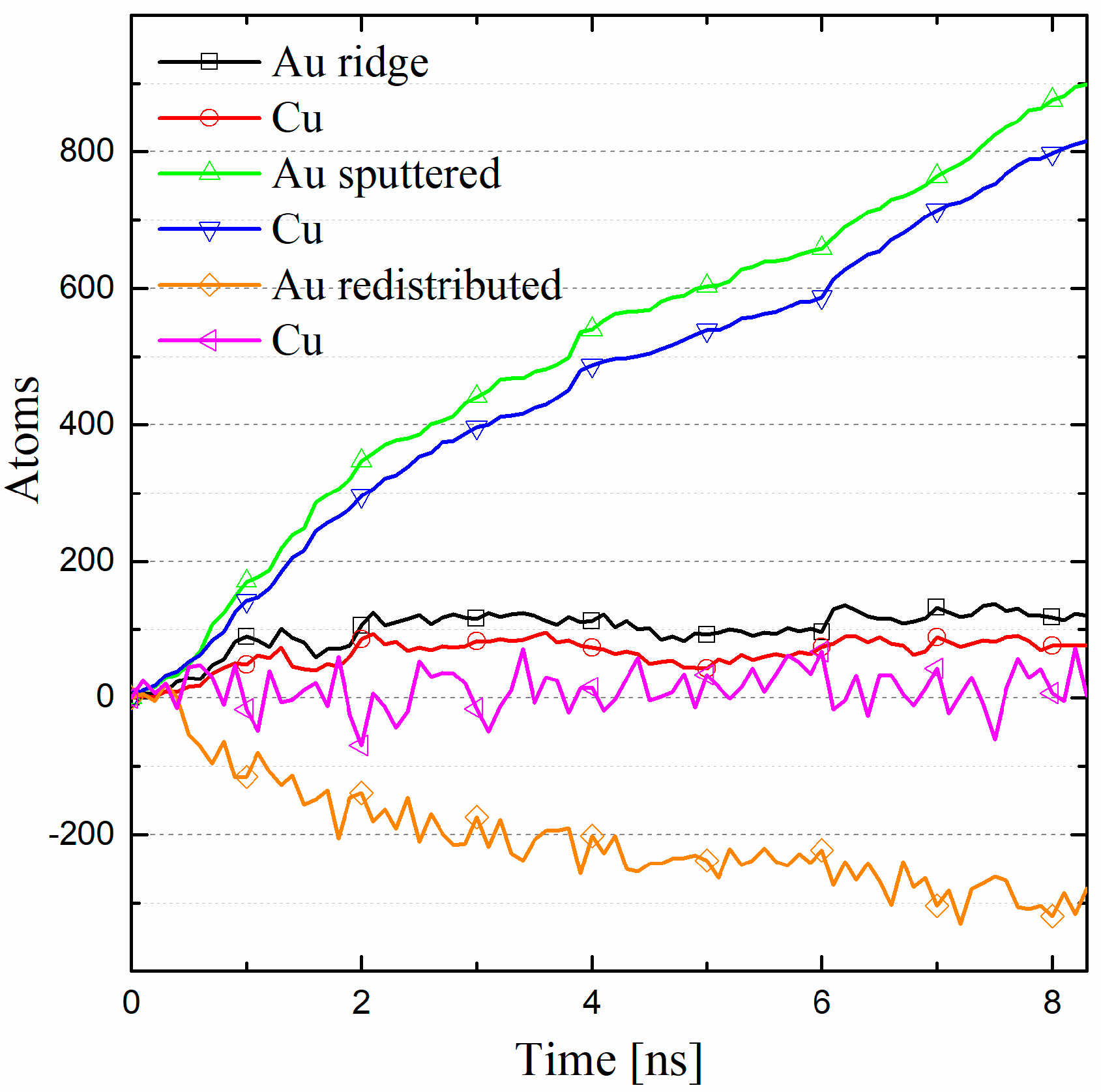
We must also analyze whether there are differences in the relocation of species with different mobility in the wave pulse. Figure 6 analyzes the atoms displaced to different positions in a 50% alloy. This allows us to analyze the tendency of species to move in a certain direction. However, these curves may vary slightly depending on the angle of incidence. Regarding sputtering, it can be observed that Au has preferential sputtering compared to Cu, at least for the grazing angles, but not for the intermediate angles, where the difference is very small. This fact leads to an enrichment of Au on the surface and specifically on the ridges [3]. The Au also has a tendency to return to the groove; in this way, the boundary atoms are fundamentally Cu atoms responsible for the amorphization of the lattice. These in-depth phase separation processes lead to the formation of patterns [33]. In short, it appears that Au bounces off the amorphous Cu lattice and either deposits on the ridge or disperses and returns to the groove.

Figure 6.
Number of displaced particles of each species for a 50% Au-Cu alloy bombarded at 70°. The figure illustrates the distribution of atoms in ridges, sputtered atoms, and those redistributed within the material.
3.4. Relocation Cross-Sections
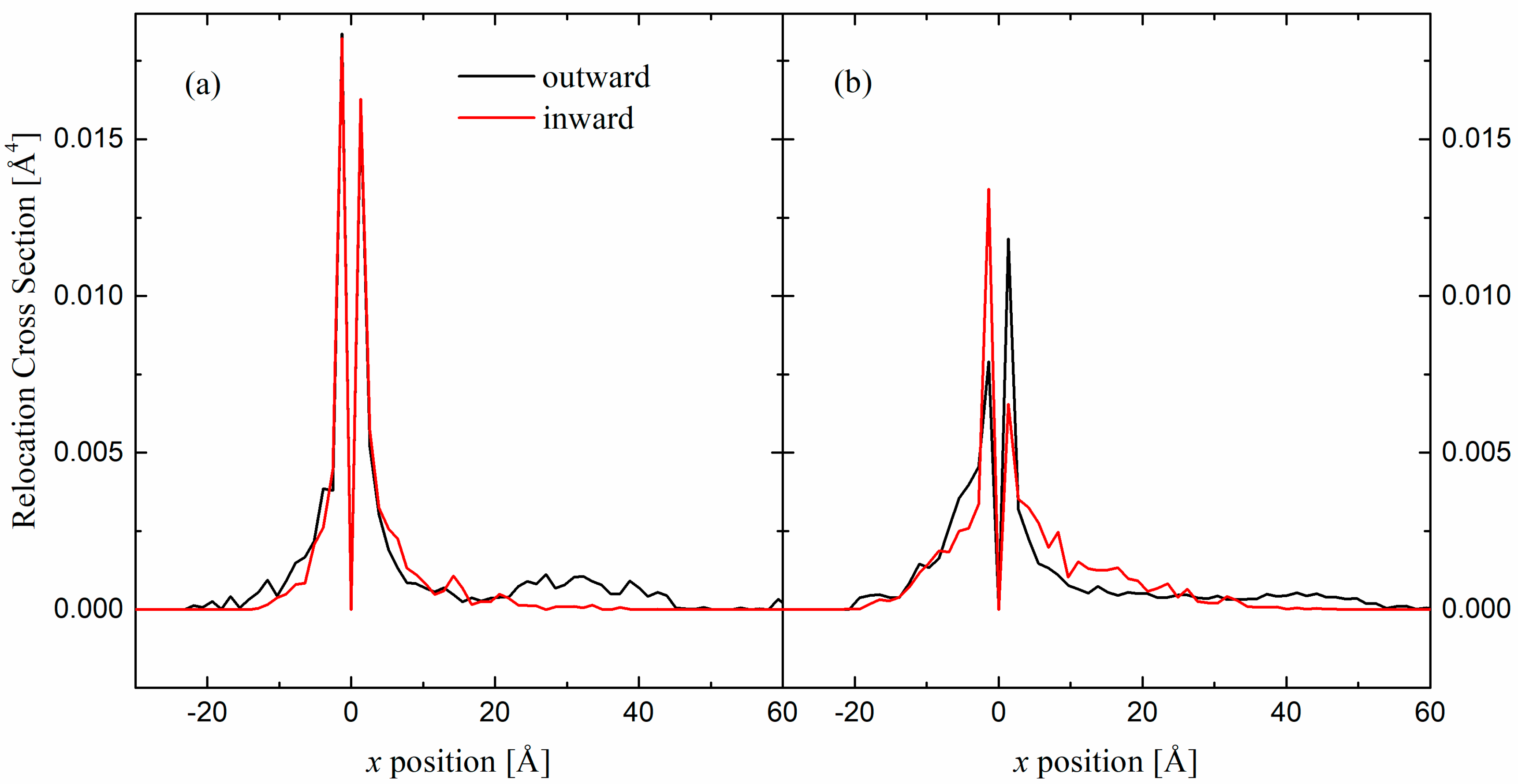
We analyze the phenomenon of ripple formation from the point of view of the relocation cross-sections [34]. In our case, we have calculated the relocation cross-section (outward), defined as the probability that an atom initially located at position (x, dx) is relocated to position (x + z, dz) after a fluence δϕ. From this section, the probability can be directly obtained that an atom initially at position (x − z, dz) is relocated to (x, dx) after fluence δϕ (inward section). In summary, sections are obtained by counting the atoms that change position and dividing them by the layer width, density, and fluence. Figure 7 shows the inward and outward sections for the pure Cu substrate and the alloy of equal concentration. The cross-sections are symmetric at short distances for the crystalline material (Figure 7a). In the case of amorphous material, short-range material filling imbalances occur (Figure 7b). In contrast, while the crystalline material facilitates structure formation via outward displacement from the output layer, the amorphous material leads to short-range void and interstitial formation by atoms entering and leaving the layer. In short, the greater number of defects generated in amorphous solids increases the local mobility of atoms. However, this mobility is short-range and does not affect the process in question.

Figure 7.
Horizontal relocation cross-sections for position x = 0 Å and an angle of incidence of 50° and two surfaces of different composition (at.% Cu): (a) 100 and (b) 50 as a function of the final position (outward section) or the initial position (inward section).
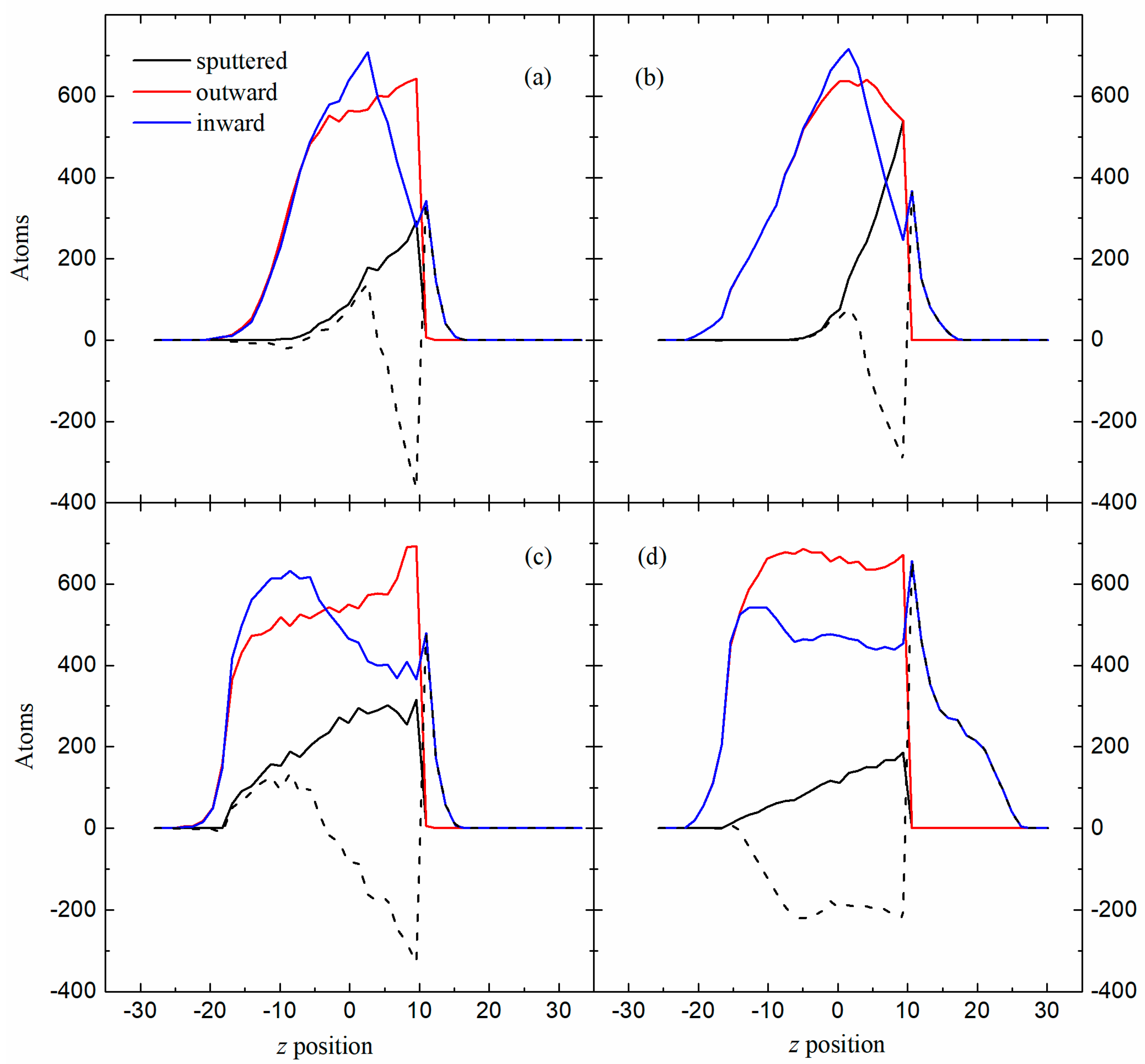
From the cross-sections, all the atoms that arrive or leave a given layer can be calculated. Figure 8 shows sputtered atoms and outward and inward relocated atoms for the Cu substrate and for the alloy of equal concentration bombarded at 50° and 70°. In this case, we will be interested in analyzing it in vertical layers. In the 70° curves, the greatest weight of sputtering is observed in the case of Cu (Figure 8b). In fact, in both cases, sputtering is the dominant factor. In the curves, for example, of 50% Au-Cu (Figure 8a), it can be observed how the difference between the relocated atoms (those that leave minus those that arrive) may even turn out to be locally greater than that of sputtered atoms. However, the net balance of relocated atoms along the entire z-axis does not exceed the total number of sputtered atoms. This fact occurs in both cases for the alloy (70°, Figure 8a, and 50°, Figure 8c) and in the case of pure Cu bombarded with a grazing angle, that is, in the cases in which sputtering predominates (Figure 8b). We must understand that the difference in the number of atoms that arrive and leave a layer is a measure of the redistribution effect. Furthermore, this effect is especially important in the case of pure Cu bombarded at intermediate angles (Figure 8d), where the total number of sputtered atoms does not exceed the total number of redistributed atoms [20]. Redistribution also induces differences in amorphous materials. Thus, in Figure 8c,d, it is observed that, although the bottom of the groove is emptied, this same bottom is filled again with atoms from other layers. However, this effect does not occur in crystalline materials, where that material rises vertically to form the ridges.
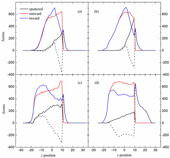
Figure 8.
Sputtered atoms, outward and inward relocated atoms as a function of the z position for two surfaces of different composition (at.% Cu): (a,c) 50 and (b,d) 100 and two angles of incidence: (a,b) 70° and (c,d) 50°. The dashed line shows the difference between the atoms that arrive and the atoms that leave that layer.
4. Conclusions
In this study, we use MD simulations to investigate the mechanisms of nanoscale pattern formation on Au-Cu alloy surfaces irradiated by Ar cluster ion beams, focusing on the effects of alloy composition and incident angles. The fluence deposited on the material is the same in all cases. Two more details characterize the simulations: they have been performed at low temperatures so that ballistic effects predominate over diffusive effects, and to accelerate the ripple formation effect on the surface, a very simple model has been used, characterized by bombardment on a delimited surface in the form of a strip.
Key findings show that intermediate-composition alloys exhibit significant suppression of ripple height and depth due to irradiation-induced amorphization. When bombarded with alloys of mixtures of similar concentration, an amorphization process occurs in the crystalline lattice. This effect causes the wave pulse to expand horizontally and drastically decrease its height.
Sputtering and redistribution are the physical processes that can explain this phenomenon. The observation of maximum sputtering and minimal horizontal and vertical displacements at intermediate incidences suggests that sputtering is the predominant effect within this angular interval. In contrast, the explanation for grazing incidence proves more difficult and does not lean toward either of the two processes since the sputtering becomes minimal, the horizontal displacement depends on the mobility of the material, and the vertical displacement becomes quite small. However, the redistribution factor becomes negative for the entire angular range in alloys, indicating sputtering outweighs atomic redistribution, a behavior that contrasts with pure metals. Therefore, sputtering is once again the predominant effect at grazing angles.
In short, it appears that alloys are more susceptible to amorphization in processes far from equilibrium, such as bombardment. An amorphous solid hampers surface redistribution processes to the point that sputtering predominates throughout the entire angular range of incidence.
Finally, we analyze the differences in repositioning between a pure material and an alloy with a similar concentration. In the latter material, the horizontal cross-sections are asymmetric on a short scale, which means that an alteration of the structure occurs at a local level. Furthermore, the formation of a large ridge by direct outward transfer of atoms is visualized only in the case of a pure material. The accounting of atoms per layer sputtered, ejected outward or returned inward along the z-axis allows us to visualize the importance of sputtering in the process. If along the z-axis the net balance of atoms expelled by redistribution is greater than that expelled by sputtering, it means that the first process will predominate.
The simulation time limitations of MD are undeniable. However, future lines of work related to this article would include experimental verification of the results presented herein. From a numerical perspective, other bimetallic combinations should be used, and it should be demonstrated that the same effects occur.
Author Contributions
Methodology, J.C.J.-S.; Software, J.C.J.-S.; Investigation, S.M. and P.P.; Writing—original draft, J.C.J.-S.; Writing – review & editing, S.M. and P.P.; Funding acquisition, S.M. All authors have read and agreed to the published version of the manuscript.
Funding
This work was supported by the Universidad Complutense of Madrid under the Project for Research Groups (Bioelectromagnetism Research Group 910305).
Institutional Review Board Statement
Not applicable.
Informed Consent Statement
Not applicable.
Data Availability Statement
The volume of data handled is such that it will only be available upon request to the authors.
Conflicts of Interest
The authors declare no conflicts of interest.
References
- Kim, J.; Ha, N.; Kim, J.; Joe, M.; Lee, K.; Cuerno, R. One-dimensional pattern of Au nanodots by ion-beam sputtering: Formation and mechanism. Nanotechnology 2011, 22, 285301. [Google Scholar] [CrossRef] [PubMed]
- Vázquez, L.; Redondo-Cubero, A.; Lorenz, K.; Palomares, F.J.; Cuerno, R. Surface nanopatterning by ion beam irradiation: Compositional effects. J. Phys. Condens. Matter 2022, 34, 333002. [Google Scholar] [CrossRef]
- Bharathi, M.S.; Ramanarayan, H.; Zhang, Y.W. Pattern formation and nonlinear evolution in alloy surfaces by ion-beam sputtering. Appl. Phys. Lett. 2011, 99, 083103. [Google Scholar] [CrossRef]
- Bradley, R.M.; Harper, J.M.E. Theory of ripple topography induced by ion bombardment. J. Vac. Sci. Technol. A 1988, 6, 2390. [Google Scholar] [CrossRef]
- Cuerno, R.; Barabasi, A.L. Dynamic scaling of ion-sputtered surfaces. Phys. Rev. Lett. 1995, 74, 4746. [Google Scholar] [CrossRef]
- Chason, E.; Aziz, M.J. Spontaneous formation of patterns on sputtered surfaces. Scr. Mater. 2003, 49, 953–959. [Google Scholar] [CrossRef]
- Carter, G.; Vishnyakov, V. Roughening and ripple instabilities on ion-bombarded Si. Phys. Rev. B 1996, 54, 17647. [Google Scholar] [CrossRef] [PubMed]
- Norris, S.A.; Samela, J.; Bukonte, L.; Backman, M.; Djurabekova, F.; Nordlund, K.; Madi, C.S.; Brenner, M.P.; Aziz, M.J. Molecular dynamics of single-particle impacts predicts phase diagrams for large scale pattern formation. Nat. Commun. 2011, 2, 276. [Google Scholar] [CrossRef]
- Lopez-Cazalilla, A.; Ilinov, A.; Nordlund, K.; Chowdhury, D.; Bhattacharyya, S.R.; Ghose, D.; Mondal, S.; Barman, P.; Djurabekova, F.; Norris, S. Pattern formation on ion-irradiated Si surface at energies where sputtering is negligible. J. Appl. Phys. 2018, 123, 235108S. [Google Scholar] [CrossRef]
- Norris, S.A.; Brenner, M.P.; Aziz, M.J. From crater functions to partial differential equations: A new approach to ion bombardment induced nonequilibrium pattern formation. J. Phys. Condens. Matter 2009, 21, 224017. [Google Scholar] [CrossRef]
- Umbach, C.C.; Headrick, R.; Chang, K.C. Spontaneous nanoscale corrugation of ion-eroded SiO2: The role of ion-irradiation-enhanced viscous flow. Phys. Rev. Lett. 2001, 87, 246104. [Google Scholar] [CrossRef] [PubMed]
- Norris, S.A. Stress-induced patterns in ion-irradiated silicon: Model based on anisotropic plastic flow. Phys. Rev. B 2012, 86, 235405. [Google Scholar] [CrossRef]
- Bradley, R.M.; Hofsäss, H. Nanoscale patterns produced by self-sputtering of solid surfaces: The effect of ion implantation. J. Appl. Phys. 2016, 120, 074302. [Google Scholar] [CrossRef]
- Shenoy, V.; Chan, W.; Chason, E. Compositionally modulated ripples induced by sputtering of alloy surfaces. Phys. Rev. Lett. 2007, 98, 256101. [Google Scholar] [CrossRef]
- Bradley, R.M.; Shipman, P.D. Spontaneous pattern formation induced by ion bombardment of binary compounds. Phys. Rev. Lett. 2010, 105, 145501. [Google Scholar] [CrossRef] [PubMed]
- Facsko, S.; Dekorsy, T.; Koerdt, C.; Trappe, C.; Kurz, H.; Vogt, A.; Hartnagel, H.L. Formation of ordered nanoscale semiconductor dots by ion sputtering. Science 1999, 285, 1551–1553. [Google Scholar] [CrossRef]
- Bradley, R.M.; Shipman, P. A surface layer of altered composition can play a key role in nanoscale pattern formation induced by ion bombardment. Appl. Surf. Sci. 2012, 258, 4161–4170. [Google Scholar] [CrossRef]
- Zhou, Z.; Cui, J.; Hou, Q. Role of mass redistribution on nanoripple formation and propagation: A molecular dynamics simulation study. Appl. Surf. Sci. 2022, 585, 152630. [Google Scholar] [CrossRef]
- Lopez-Cazalilla, A.; Nordlund, K.; Djurabekova, F. Formation of parallel and perpendicular ripples on solid amorphous surfaces by ion beam-driven atomic flow on and under the surface. Phys. Rev. Mater. 2023, 7, 036002. [Google Scholar] [CrossRef]
- Jiménez-Sáez, J.C.; Muñoz, S.; Palacios, P. Nanoscale pattern formation on surfaces by cluster ion beam irradiation. Phys. Scr. 2024, 99, 085984. [Google Scholar] [CrossRef]
- Jiménez-Sáez, J.C.; Muñoz, S.; Palacios, P. Cluster ion beam irradiation at low energy and surface pattern formation. Nucl. Instrum. Methods Phys. Res. B 2025, 563, 165707. [Google Scholar] [CrossRef]
- Cuerno, R.; Kim, J.-S. A perspective on nanoscale pattern formation at surfaces by ion-beam irradiation. J. Appl. Phys. 2020, 128, 180902. [Google Scholar] [CrossRef]
- Okamoto, H.; Chakrabarti, D.J.; Laughlin, D.E.; Massalski, T.B. The Au-Cu (gold-copper) system. Bull. Alloy Phase Diagr. 1987, 8, 454–473. [Google Scholar] [CrossRef]
- Adelman, S.A.; Doll, J.D. Generalized Langevin equation approach for atom/solid-surface scattering: General formulation for classical scattering off harmonic solids. J. Chem. Phys. 1976, 64, 2375–2388. [Google Scholar] [CrossRef]
- Ackland, G.J.; Vitek, V. Many-body potentials and atomic-scale relaxations in noble-metal alloys. Phys. Rev. B 1990, 41, 10324–10333. [Google Scholar] [CrossRef] [PubMed]
- Nosé, S. A molecular dynamics method for simulations in the canonical ensemble. Mol. Phys. 1984, 52, 255–268. [Google Scholar] [CrossRef]
- Bernardes, N. Theory of solid Ne, A, Kr, and Xe at 0 K. Phys. Rev. 1958, 112, 1534–1539. [Google Scholar] [CrossRef]
- Lopez-Cazalilla, A.; Ilinov, A.; Nordlund, K.; Djurabekova, F. Modeling of high-fluence irradiation of amorphous Si and crystalline Al by linearly focused Ar ions. J. Phys. Condens. Matter 2019, 31, 075302. [Google Scholar] [CrossRef]
- Brink, T.; Sopu, D.; Albe, K. Solid-state amorphization of Cu nanolayers embedded in a Cu64Zr36 glass. Phys. Rev. B 2015, 91, 184103. [Google Scholar] [CrossRef]
- Cleveland, C.L.; Luedtke, W.D.; Landman, U. Melting of gold clusters. Phys. Rev. B 1999, 60, 5065–5077. [Google Scholar] [CrossRef]
- Kreth, M.; Entel, P.; Kadau, K.; Meyer, R. Molecular-dynamics study of the local symmetry changes in metallic liquids. Phase Transit. 2004, 77, 89–100. [Google Scholar] [CrossRef]
- Bailey, N.P.; Schiotz, J.; Jacobsen, K.W. Simulation of Cu-Mg metallic glass: Thermodynamics and structure. Phys. Rev. B 2004, 69, 144205. [Google Scholar] [CrossRef]
- Lively, M.A.; Holybee, B.; Toriyama, M.; Facsko, S.; Allain, J.P. Nonlinear compositional and morphological evolution of ion irradiated GaSb prior to nanostructure formation. Sci. Rep. 2020, 10, 8253. [Google Scholar] [CrossRef]
- Jiménez-Rodríguez, J.J.; Pérez-Martín, A.M.C.; Peinador, J.A. Calculation of the ballistic relocation cross-sections. Nucl. Instrum. Methods B 1992, 67, 504–508. [Google Scholar] [CrossRef]
Disclaimer/Publisher’s Note: The statements, opinions and data contained in all publications are solely those of the individual author(s) and contributor(s) and not of MDPI and/or the editor(s). MDPI and/or the editor(s) disclaim responsibility for any injury to people or property resulting from any ideas, methods, instructions or products referred to in the content. |
© 2025 by the authors. Licensee MDPI, Basel, Switzerland. This article is an open access article distributed under the terms and conditions of the Creative Commons Attribution (CC BY) license (https://creativecommons.org/licenses/by/4.0/).