Article

Recovery Motion Analysis for False Ceiling Inspection Robot

by
Matthew S. K. Yeo
*,†,
Zhenyuan Yang
,
S. M. Bhagya P. Samarakoon
and
R. E. Mohan
Engineering Product Development, Singapore University of Technology and Design, 8 Somapah Road, Singapore 487372, Singapore
*
Author to whom correspondence should be addressed.
These authors contributed equally to this work.
Appl. Sci. 2025, 15(9), 4616; https://doi.org/10.3390/app15094616
Submission received: 4 March 2025 / Revised: 4 April 2025 / Accepted: 11 April 2025 / Published: 22 April 2025

Abstract

:
The false ceiling plenum is a common and essential part of building infrastructure. However, false ceiling infrastructure requires constant maintenance, which is cumbersome and dangerous for humans since they have to work at high heights and conduct repetitive actions for false ceiling panel replacement. As a solution, robots have been developed to inspect false ceilings. However, these robots can fall during navigation in false ceilings, such as in rugged areas. Therefore, this paper discusses the self-righting capabilities implemented on a false ceiling inspection robot known as FalconX. Mechanisms that aid in self-righting the robot back to a moving position after being toppled due to obstacles within the false ceiling environment were explored, along with their force analysis. Simulations were conducted in Gazebo environments and real hardware experiments were conducted to validate the robot’s self-righting capabilities. The experimental results confirm the self-righting capability of the robot.

1. Introduction

False ceilings are often used in buildings to store and hide disorderly but essential building infrastructure [1,2] such as heating, ventilation ducts and air-conditioning (HVAC), electrical wiring, and plumbing systems [3]. The false ceiling space, also known as the plenum, acts as an infrastructural measure to limit fire damage [4] and regulate the thermal conditions [5] and acoustical capabilities [6,7] of the main space below. Maintenance works on false ceilings have to be conducted on a regular basis. Otherwise, there would be potential health and safety compromises to building occupants because of pest infestations and other forms of degradation in false ceilings [8]. Infrastructural elements could be tampered with by pests inhabiting false ceilings if maintenance is neglected. Pollutants or airborne pathogens can enter damaged HVAC vents and circulate in the building, spreading diseases through the air if maintenance is not regularly carried out. Thus, sporadic checks of false ceilings can lead to the failure of amenities such as HVAC or lighting fixtures, causing problems for the occupants using the rooms below.
The need for frequent inspection and maintenance puts a heavy strain on the skilled workforce. These people have to work at height and continually with the risk of falls. Falls from high heights can cause severe contusions, bone fractures, and other injuries. These injuries can prevent human workers from working for extended periods of time while they recover. Maintenance companies can also face financial losses and manpower shortages when injured personnel are unable to work.
The existing false ceiling maintenance process is greatly dependent on human labour. With the myriad of obstructions that exist within false ceilings and the poorly lit conditions, there are many risks faced by human workers during the inspection phase of false ceiling maintenance. The components in the plenum are often laid for convenience during construction instead of ease of access and maintenance. Disorganised wiring, piping and the haphazard arrangement of other elements can cause higher occurrences of injuries to human workers. This does not exclude unexpected encounters with pest infestations [9] or the dislodging of heavy items while performing maintenance in the plenum. Each false ceiling site is different across every building and sometimes varies among individual floors due to differing requirements in fixtures and amenities. Design guidelines are often neglected for ease of installation and meeting tight deadlines. Wiring and the compacted arrangement of fixtures close together can pose as navigational and visual obstructions for inspection tasks, even for robotic aids.
There are studies that look into automated inspection solutions to alleviate the burden on skilled human labour for false ceiling inspection works. Many research interests in robotic solutions have been taken up in recent years to aid human workers in the field of maintenance for the built environment [10,11]. These mobile robotic solutions are often made small and lightweight to navigate tight and hard-to-reach spaces and are often installed with cameras to conduct visual inspection [12,13,14,15].
However, using robotic means for such tasks still carries the risk of having the robot encounter obstacles within the false ceiling plenum and being stopped prematurely before completing its visual sweep of the area. With the haphazard layout of amenities in the false ceiling plenum, robots can get stuck due to its form or locomotion methods, getting caught by stray cables and pipes or the crowded layout of infrastructure within false ceilings. This is counterproductive for inspection works as manpower would still then be required for the manual retrieval of the robot.
Self-righting robotic mechanisms have been explored in works such as [16] for toppled robots on inclined planes [17,18], regarding usage of added tail mechanisms for self-righting, and even self-righting mechanisms used for jumping robots [19,20]. However, little research regarding self-righting robots has been conducted for robots working within complex and haphazard environments such as a false ceiling plenum.
This study contributes to this field by conducting an analysis of the self-righting motion of a novel false ceiling inspection robot called FalconX. FalconX builds upon the existing class of Falcon false ceiling inspection robots for improved surveys of false ceilings. The research goal of this study was to determine and analyse a mathematical model for the self-righting mechanism of FalconX and validate the model using the robot in real life.
Section 2 of this paper discusses the typical fixtures found in false ceilings, the need for their regular maintenance and how robotic aid can alleviate issues faced by human workers during inspection. Section 3 details the Falcon class of inspection robots and their capabilities and limitations. Section 4 introduces the mechanisms added to the FalconX robot for re-balancing after being toppled by fixtures in the false ceiling setting. Section 5 discusses the force analysis for the re-balancing mechanism. Section 6 then concludes this paper with future directions to refine the FalconX robot for enhanced false ceiling inspections.

2. Background

The most common type of false ceiling is the concealed panel grid suspended ceiling used in many office buildings [21]. It is often accessed by means of specific access panels or hatches to reach the plenum. However, using the access panels carries work risks as it requires the human worker to be familiar with the scope of their tasks. Mishandling of the access panels prevents proper sealing of the false ceiling space when the maintenance work is completed and allows entry to pests that can reside in the dark conditions, which are ideal for them to hide from their predators in the urban environment. The lack of standardisation in the design aspect for false ceiling panel dimensions makes it difficult for regulated safety measures in using access panels and how to design them for repeated use and incident prevention.

2.1. Problems Encountered During Indoor False Ceiling Maintenance

Concealed false ceilings have the issue of being neglected as the components are hidden from view. Problems when false ceilings are left unattended over long periods of time include, but are not limited to, (a) the presence of pests and rodents that enter false ceilings through crevices or gaps, (b) ventilation and plumbing system leakage that leads to hazardous chemicals and vapours circulating through the building, (c) mould or stains on false ceiling panels, and (d) the eventual damage or breakdown of infrastructure due to neglect and deterioration. These problems can escalate in severity and incur large repair costs over time or even cause health ailments for occupants. To counter such issues, Facility Management (FM) inspection works and examinations of the structural integrity of buildings themselves are often conducted regularly for the inspection of support structures that reside above false ceilings.
Moreover, removing a single false ceiling panel is unlikely to enable a human worker to view the entire false ceiling plenum since, without the aid of additional equipment such as expensive and bulky endoscopic cameras, the worker’s field of view would likely be obstructed by the complex and non-systematic arrangement of infrastructure within the false ceiling plenum. Hence, the removal of multiple panels at different points of the false ceiling is necessary to comprehensively inspect a false ceiling interior. This process of removing and replacing panels requires the constant and cumbersome shifting of equipment to allow a human worker to reach a false ceiling at a height; this also adds to the wear and tear of false ceiling access panels. These issues could be mitigated if robot-inclusive principles were implemented for false ceiling plenums [22].
These robot-inclusive principles would be cumbersome to implement retroactively for existing buildings. Mobile robots could enable automated robotic inspections within false ceilings for buildings. The dimensions of the robot would need to account for a site’s layout in terms of robot-inclusive Accessibility and Observability principles. Thus, these robots need to be designed as small and lightweight to nimbly navigate within constrained spaces, while still accounting for the robotic components for inspection tasks. For other sites, spatial information of false ceilings would be needed to design a customised robot suited for the site that could move efficiently through the zone for comprehensive scans of the false ceiling.

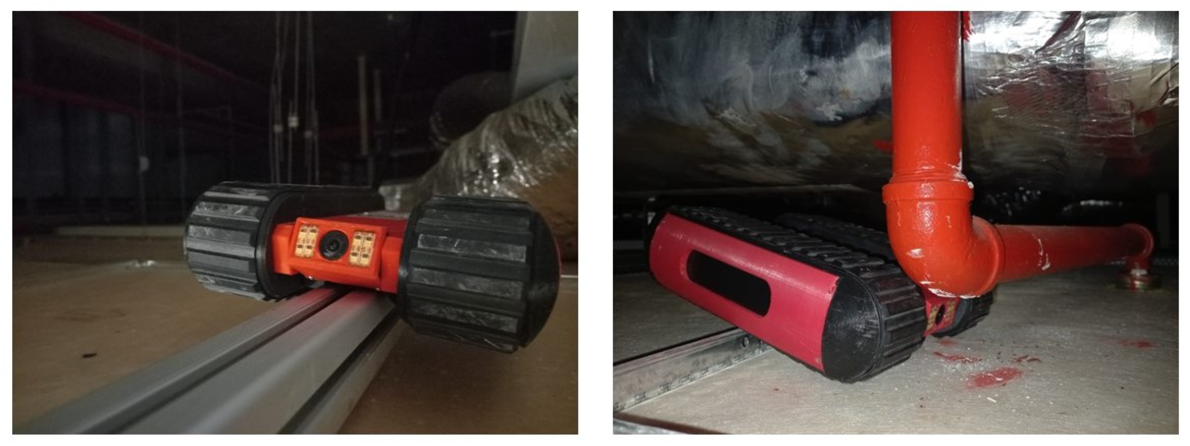
2.2. Using Mobile Robotic Solutions for False Ceiling Inspection

Using mobile robots for false ceiling inspection is a promising solution for the multiple problems encountered regarding successful false ceiling maintenance [23,24]. Robots with various designs in terms of locomotion and form factors are capable of performing tasks in the plenum that are difficult or dangerous to reach for humans. Locomotion modes by such robots can be in the form of wheels, tracks or jointed legs. These mobile robots can perform regular inspections within false ceiling plenums when equipped with visual cameras and thus minimise human intervention in the maintenance process. This would directly reduce incidents of human occupational accidents when working at high heights and injuries involving false ceiling elements or human fatigue. Prior to implementation, case studies would be examined of robots made for navigating constrained spaces and in-pipe inspections [25].
Halder et al. [26] reviewed the various types of robots used in the inspection and monitoring of built infrastructure, mostly having unmanned aerial vehicles (UAVs) and drones to conduct the tasks. The drones usually required an open space to navigate and relay information, instead of working in constrained spaces, as in our case. Lattanzi and Miller [27] also noted in their review of inspection robots that there is a trade-off between sensor technologies and locomotion capabilities for this kind of inspection robot. Thus, little work has been conducted on this specific topic of robotic aid for false ceiling inspection. Research papers found on false ceiling inspection robots are mainly centred around other versions of Falcon robots. Other inspection robots gathered in the literature review were not designed for obstacle crossing [28,29] or had cumbersome equipment such as tethers and excessive points in the design that could cause the robot to become trapped or entangled [30,31].
Commercial designs for inspection robots in tight spaces such as SuperDroid [32] utilised tracks for robot locomotion. These designs would face the issue of being trapped by the low-height false ceiling support frame when the frame is between the locomotion system, preventing the main body from extracting itself. Moreover, crawler robots made by Uplink Robotics and Techmatics use large wheels to avoid this issue but face a problem where they are unable to access short crawlspaces. These robots were not designed for self-righting capabilities. The limitations of these robots and the operation environment, ability of equipment working within the isolated false ceiling, or inspection range would not match the requirements of the task. This shows that using robotic aid for false ceiling inspection is still a potential research area worth exploring.
Koh et al. [33] described a duct-cleaning mobile robot using cameras and tethered means to navigate in ducts and a laser system to track the cross-section within the duct. This design had the basic requirements an inspection robot would need for its tasks. However, its large size is not suitable for our use case of an entire false ceiling zone.
Filipek and Kaminski [34] detailed a robot built for inspection with a mounted arm end-effector, with a camera separately mounted on the robot’s vertical support wheel, built from aluminium profiles. It was controlled remotely with attached cables. This provided a basis on what components and items would be expected of an inspection robot. However, this robot had multiple protrusions and positions whereby it could be caught by the disordered environment within a false ceiling interior, which would be counterproductive for maintenance and inspection work.
Ab Rashia et al. [35] reviewed the various robots built for in-pipe inspection and other constrained spaces. The review paper investigated findings regarding various locomotion modes, providing insights into their kinematics and behaviour within constrained environments. For our case, we focus on wheeled mobile bases as the means of locomotion. A wheeled base provides the benefits of ease of operation and replacement if needed, along with a well-researched locomotion mode to work upon.
The Mantis robot is a wall-climbing robot that detects surface defects and can work at heights due to its use of vertical adherence as a means of travel and mounting [36]. Its three-module design enables it to circumvent vertical support mullions along walls and can implement visual capabilities to inspect ceilings. However, it is limited to inspecting areas near walls due to its need for vertical mounting points for locomotion.
Self-righting robots typically involve legged or bipedal robots, using the limbs as end-effectors to push themselves off a surface and flip themselves back to their neutral position to operate their intended movements and tasks again. This function is critical for robots working in complex environments [16,37] to allow them to recover without external help in constrained areas.
Some studies regarding self-righting involve multi-legged robots [38,39]. Other research works take inspiration from nature [37], utilising an additional tail effector [17,18] or wing effectors [16,40] to achieve similar results to let robots recover their operational state after falling [41].
These robots were mainly tested under ideal conditions or used in the domain of duct inspection rather than a full false ceiling plenum. These robots were not designed to adapt to dark and disordered conditions for inspecting false ceiling interiors. The navigation requirements within disorderly structural arrangements and MEP components were not thoroughly explored in the case studies. A common type of inspection robot possesses wheel or tracked mechanisms. These mechanisms allow for easy deployment and adaptation in diverse settings, as well as having fewer components compared to legged or crawling modes of locomotion. As such, to maximise the efficacy of false ceiling robots in their inspection tasks, they should operate with minimal assistance from human operators until retrieval. This would involve determining the form factors and mechanisms to enable the robot to extract itself from scenarios whereby it gets stuck in a complex false ceiling environment by self-righting after being toppled over.
The previous versions of Falcon robots were small inspection robots that utilised tracks for locomotion [42,43,44]. They were designed for false ceiling inspections within buildings that comply with the AS/NZS 2785 and BS EN 13964 false ceiling design standards [45]. They are installed with cameras for vision, enabling human workers to control the robot and view the plenum remotely for false ceiling inspection.
The previous tracked version of the Falcon robot had issues with getting stuck due to protrusions in the false ceiling that trapped the robot in the middle, with the tracks being unable to pivot the robot away from the obstacle, or getting trapped due to the layout and positioning of the robot, as seen in Figure 1. This study thus sought to mitigate cases where such false ceiling inspection robots would become stuck in disordered false ceiling infrastructure by adding recovery mechanisms and determining the motions required for recovery.
More research is needed to develop a refined mobile robot that is lightweight and that has visual capabilities to scope out false ceiling interiors and the ability to self-right.

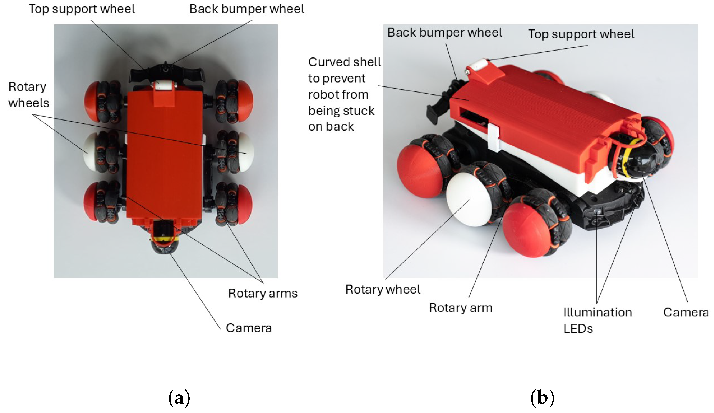
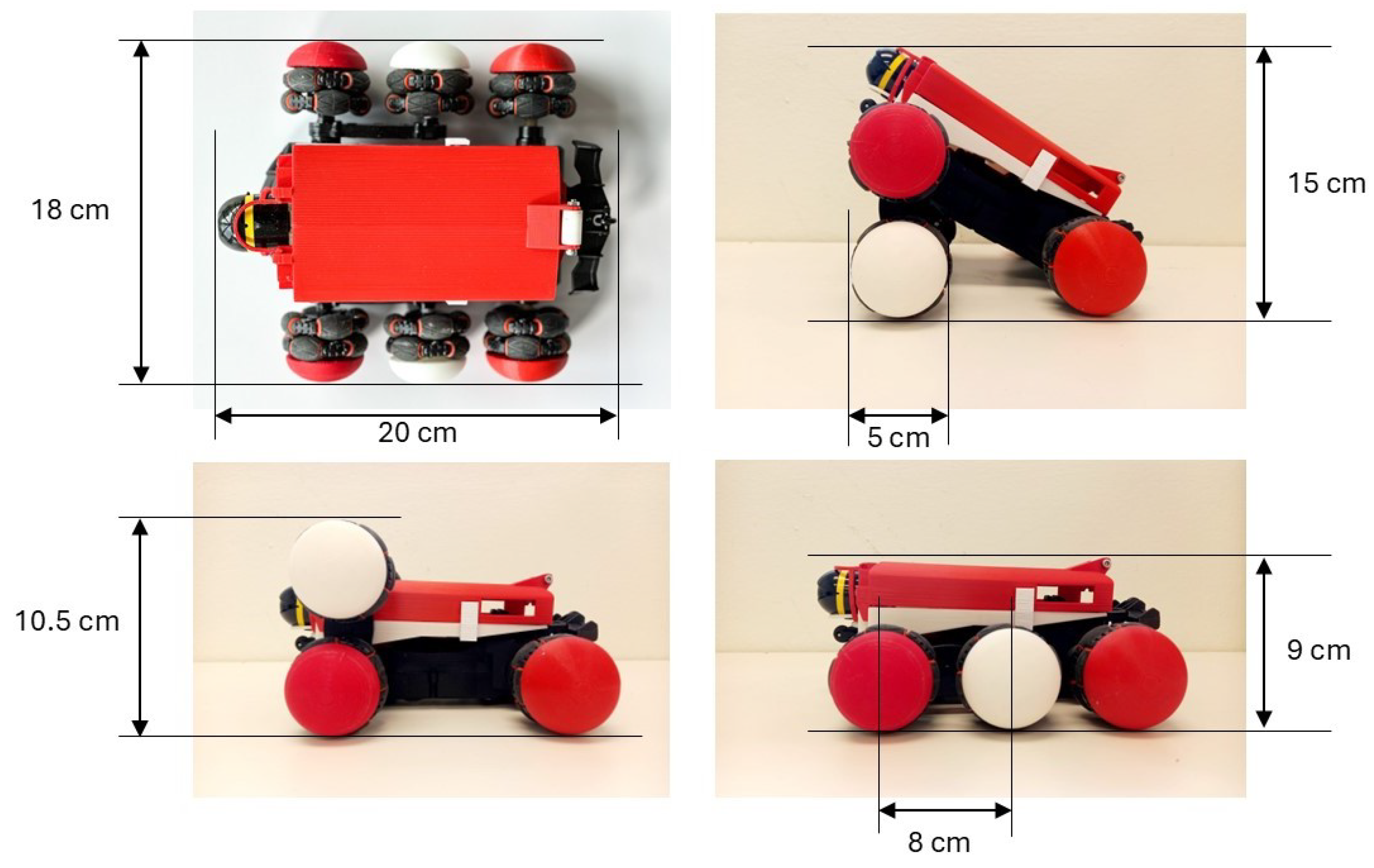
3. Materials and Methods

FalconX is a new design of false ceiling inspection robot with a recovery mechanism. The robot design built in real life is shown in Figure 2. The FalconX robot was designed by the authors and is not commercially available. The robot has a forward-facing visual camera and illumination LEDs in front of the robot for lighting up dark, false ceiling spaces during operation. The main changes involve using a reconfigurable base for the robot to actively climb over false ceiling support runners and other low-height obstacles. The robot has a mounted storage shell on top to enable it to roll over and continue moving even when flipped and provision for a compact wireless WiFi visual camera for easier maintenance and replacement. Rounded wheel caps are used to mitigate scenarios where the robot would be stuck when flipped on its side. The mass of the robot is 576 g. The dimensions of the robot’s bounding box are 20 cm in length, 18 cm in width and 9 cm in height. The wheel diameter is 5 cm, while the length of the rotary arm is 8 cm, also seen in Figure 3.
Thus, the FalconX robot utilises a new wheeled base with rotary arms, with wheels on the ends to enable the robot to circumvent false ceiling support runner grid structures. This enables the robot to avoid scenarios where it becomes stuck due to the spatial constraints within the false ceiling. The robot has zero turning radius, beneficial for navigating within the constrained space in false ceilings.
The design of the FalconX wheel base rotary wheels allows the robot to climb low-height obstacles (less than or equal to the wheel diameter of 5 cm) by rotating the rotary wheels over the obstacle and using them as a pivot to bring the robot over the obstacle, as seen in Figure 4.
Upon encountering a low-height obstacle, the robot’s rotary arms are lifted over the obstacle (Figure 4(1–5)). The rotary arms are then used to pull the main body of the robot over the low-height obstacle (Figure 4(6–9)). Once the robot passes over the obstacle, the rotary arms are returned to the original position (Figure 4(10–12)) and the FalconX robot can continue its inspection tasks.
The new model is wider at its base to reduce the probability of toppling when travelling on a flat plane, as seen in Figure 2. Figure 5 shows the first contact points of the robot with the ground plane if toppled from front and back directions.
A front bumper wheel on the front edge of the robot enables the robot to roll when it is tilted forwards. The camera holder design also keeps the robot from resting along its front edge but also lets the offset robot’s centre of gravity to self-right the robot back to its neutral position.
The robot has two support wheels at its back edge, as seen in Figure 2. The top support wheel enables continued movement even after flipping over when the rotary wheels are in the correct position. The other bumper wheel at the back edge is the first contact point when the robot is tilted backwards.
However, the efficacy of robotised false ceiling inspection is also dependent on the robot’s ability to recover and continue moving. The robot currently uses a rechargeable LiPo battery for driving and a power bank of 10,000 mAh for the camera and light modules. Current tests indicate a battery life of about 6 h for the inspection equipment and about 1 day of continuous movement of the wheels from full battery levels. The robot can then explore more of the false ceiling plenum or return to its retrieval point. The following experiments and results indicate the means of recovery for FalconX after being toppled in various directions due to potential stopping conditions within the false ceiling plenum space during operation.

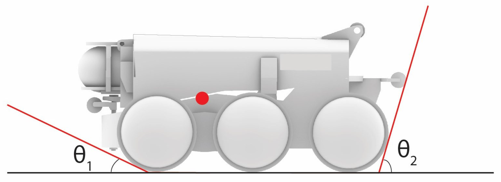
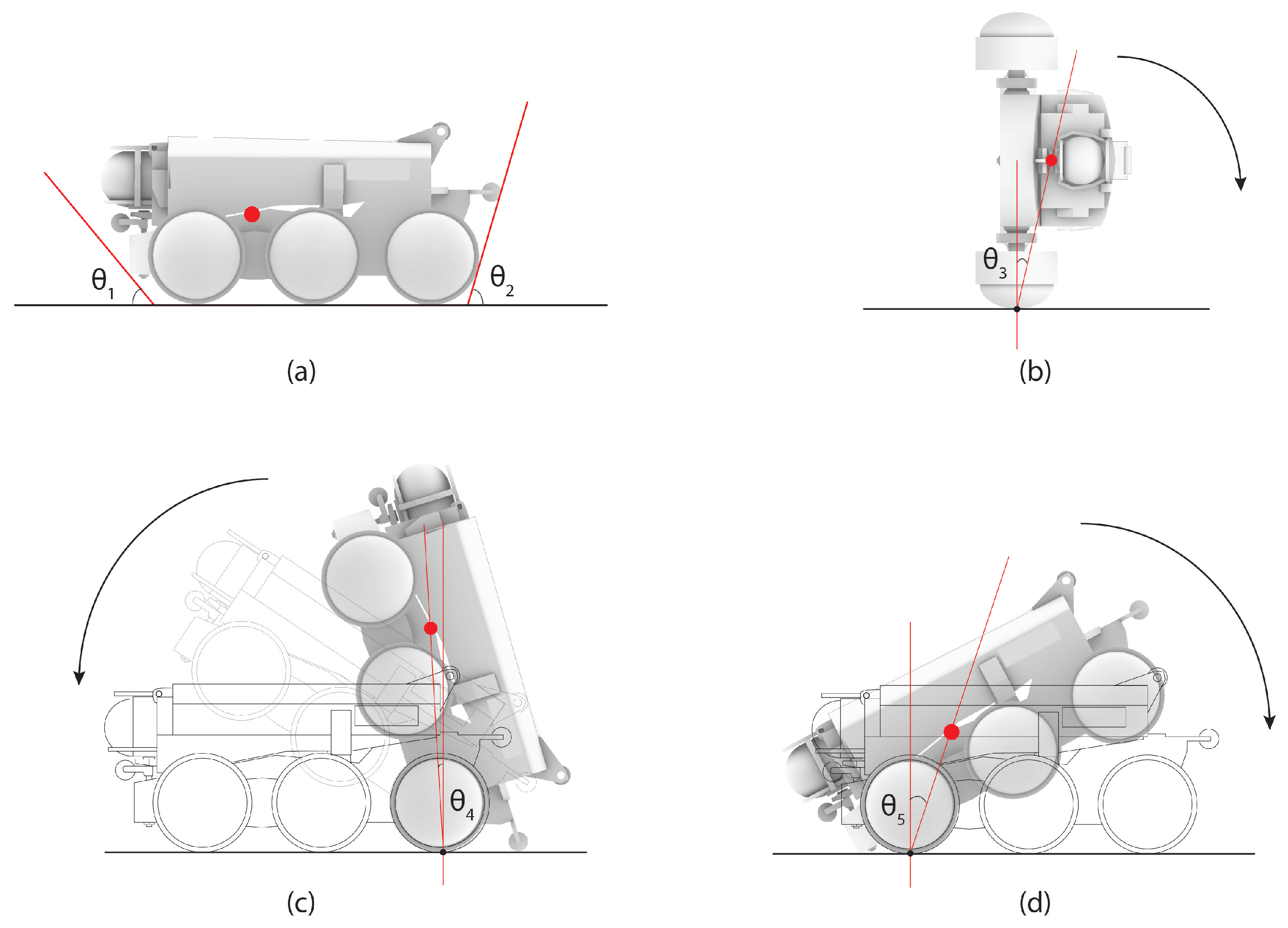
3.1. Mathematical Formulation: Jump-Start Motion

For FalconX, the main method of recovery is to position the rotary wheels perpendicular to the robot’s length and ground surface, thereby letting the robot move using a 3-point wheeled contact with the ground surface. When moving off from a stationary position, the robot experiences a jump-start that jerks the back edge of the robot with the support wheels upwards. The pose the FalconX robot has to take before self-righting is seen in Figure 6a. This is achieved by having the rotary wheels contact the ground after the robot has been flipped over.
The motion for jump-starting the robot is crucial in getting the FalconX robot into the proper position for self-righting using a vertical surface. This can be modelled using a force diagram of the flipped robot, as seen in Figure 7. The main forces to be modelled would be those acting on the support wheel and those from the rotary wheels. The torque from the rotary wheels has to overcome the robot’s inertia to provide the upwards jerk for the robot to assume the required position for self-righting.
T + m g w f h 2 = 0
w = w 2 cos P
h = w 2 2 + h 2 2 sin ( arctan h 2 w 2 + P )
T l i m = f r
Assume that after the robot reaches its flipped position, it keeps moving without further self-rotation. The torque balance equation on the robot is shown in Equation (1). Equations (2) and (3) are to calculate the horizontal and vertical distances between the contact point on the ground and the centre of gravity. Equation (4) is to calculate the torque limit to make the robot flip. These equations are based on static equilibrium and constant friction assumptions.
Solving the equations for f (the friction from the ground surface) and T (torque required to jump-start the robot to encounter the vertical surface for self-righting) with values m = 0.576 kg, g = 9.81 , h 2 = 4.5 cm, w 2 = 6.5 cm, and angle P = 25 ° (i.e., the angle required for the support wheel to rotate from its existing ground contact position to that required for contacting the wall for self-righting) results in the following.
From the calculations based on the mathematical model, the amount of torque needed by the rotary wheel was calculated to be 0.2435 Nm for this FalconX iteration as seen in Table 1. The robot’s motors would have to provide this amount of torque to the rotary wheel for the robot of this design and mass to achieve the intended self-righting pose. The robot could then self-right after achieving the required position. This is described in the next section and subsequently validated in the Results section.

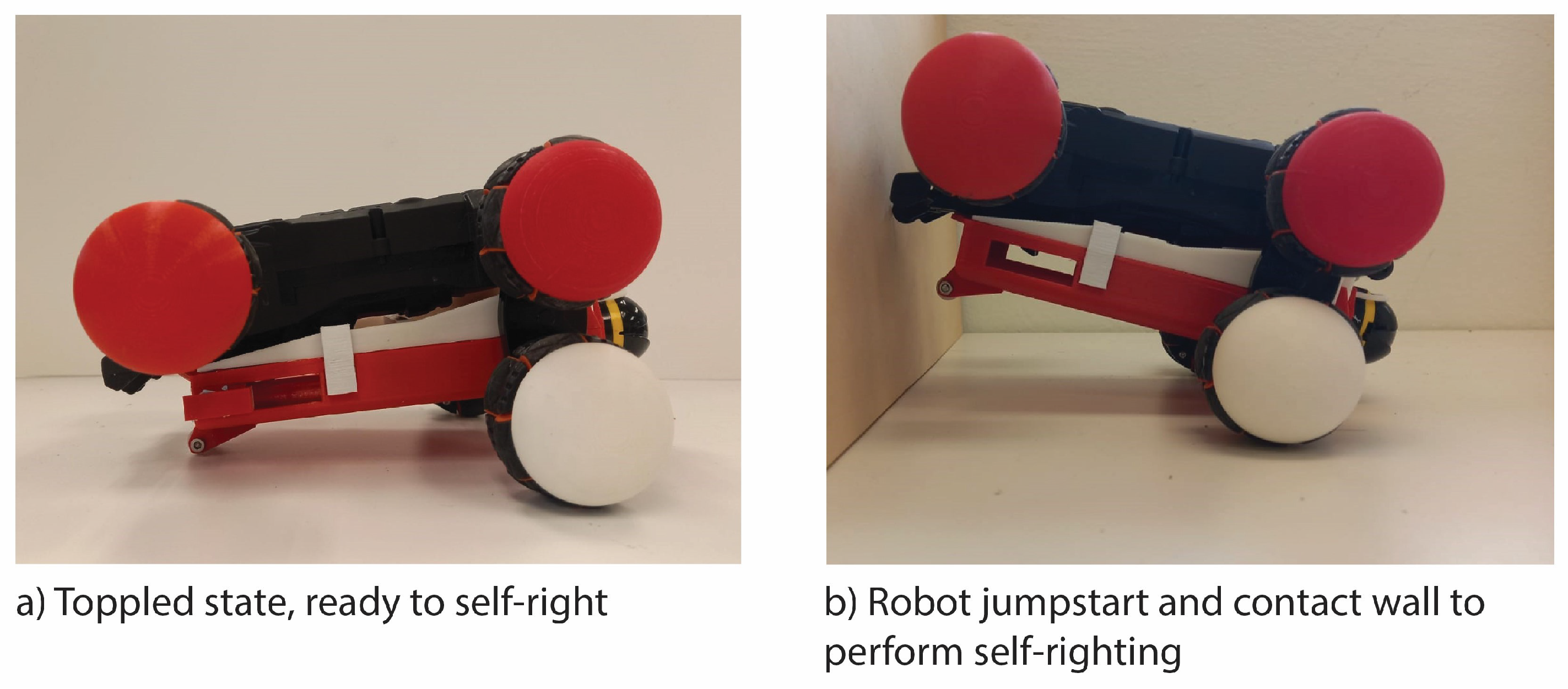
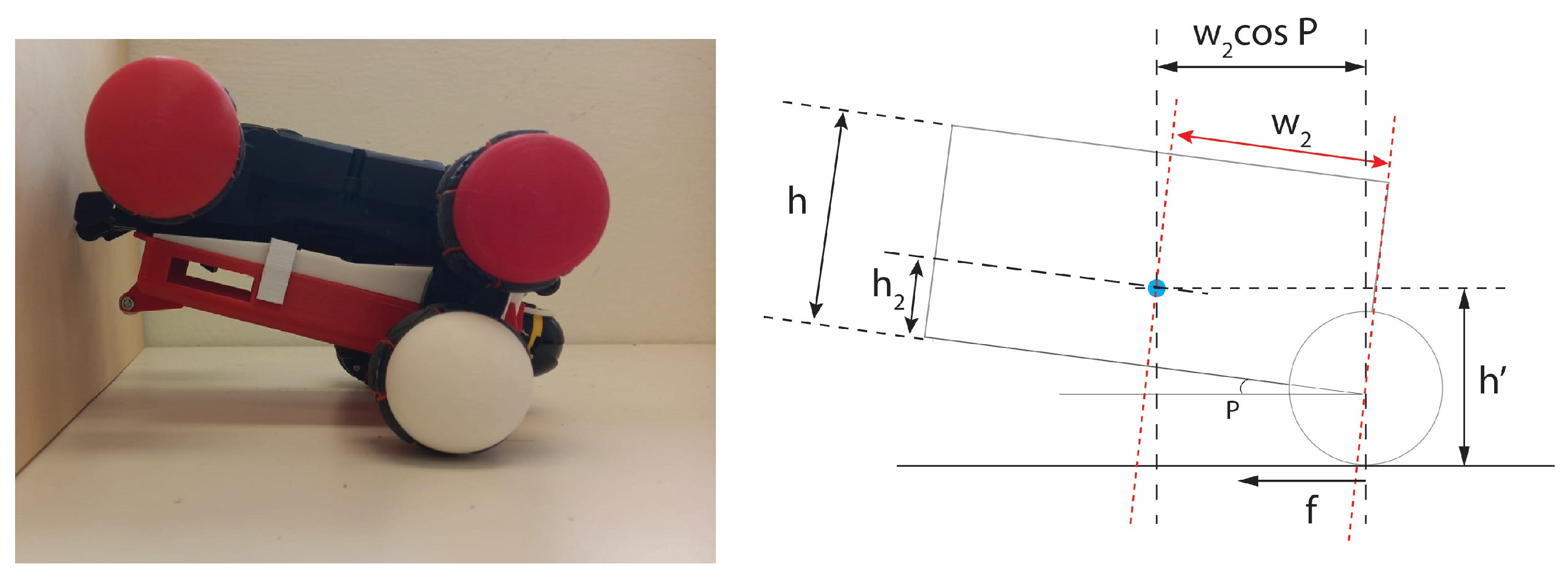
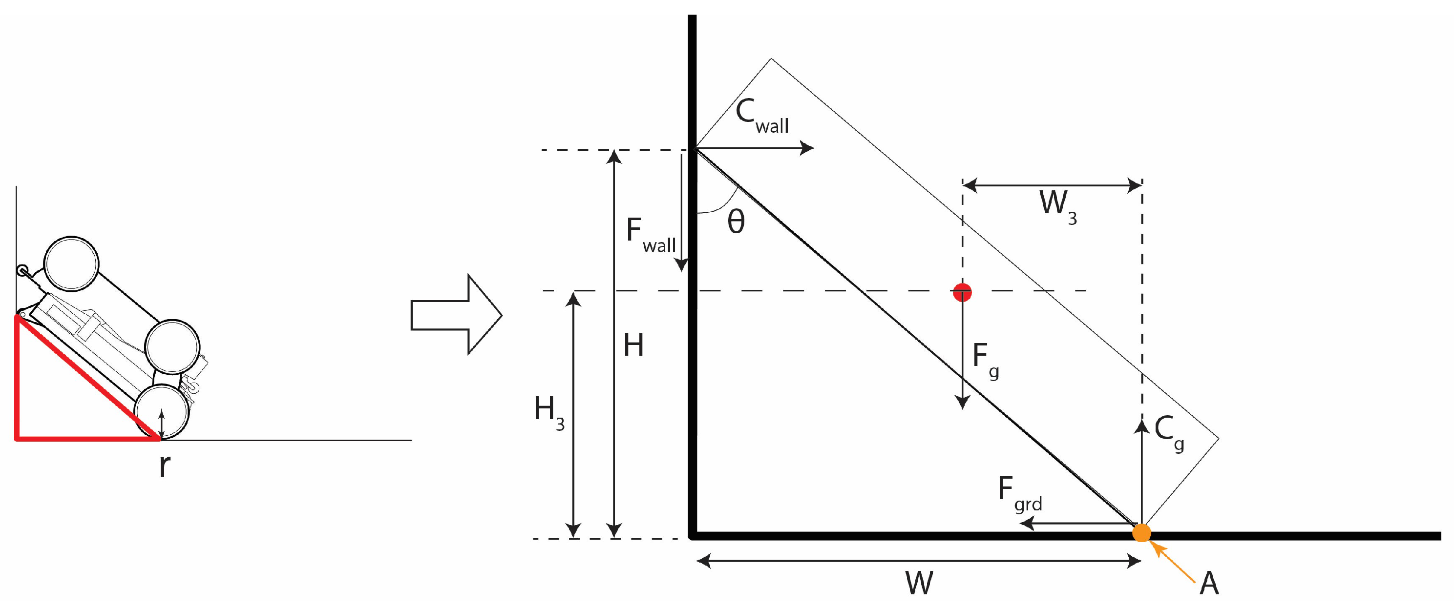
3.2. Mathematical Formulation: Self-Righting

The toppled robot (in its upside down position) contacts the wall first, with its back and top support wheels at an angle above the horizontal plane (about 10° from horizontal) to achieve the configuration for self-righting. The calculation for the torque for the self-righting process is modelled in Figure 8 with the subsequent equations.
The values for the minimum torque ( T l i m i t ) needed for flipping the robot upon contacting the vertical wall were derived using Equation (5), an analogue of the power formula. Equation (5) was derived by balancing the torque required for self-righting with the forces from the wall, ground and the robot’s own gravity; hence, the overall moment is considered to be 0 at the robot’s wheel contact point with the ground plane, labelled as A in Figure 8. The parameters are then adjusted in the context of the robot flipping over, shown in Equations (6)–(9). f g r d is the frictional contact force the robot has with the ground surface. It is also the same force for C w a l l to overcome in order to let FalconX move itself up against the wall and self-right afterwards.
M A = C w a l l H + f w a l l w + m g W 3 = 0
The equation of static equilibrium on the x-axis leads to C w a l l = f g r d and F w a l l = μ C w a l l . Thus, contextualising the terms to our case study gives
C w a l l H + μ C w a l l W = m g W 3
f g r d H μ f g r d W = m g W 3
Simplifying Equation (9) gives the formula in Equation (3) for the force required for f g r d .
f g r d = m g W 3 H μ W = m g W 3 H μ W = m g W 3 H ( 1 μ W H ) = m g W 3 H ( 1 μ tan θ )
It is assumed that the force f g r d comes from the moment that will be on the wheel of radius r, thus giving the formula for T l i m i t to be determined as
T l i m i t f g r d r = m g W 3 r H ( 1 μ tan θ )
where m is the robot’s mass, g is the gravitational constant, r is the robot’s wheel radius, h is the vertical height from the top support wheel contact point with the wall to the ground plane, h 3 is the current vertical height of the centre of mass from the ground plane, μ is the frictional coefficient between the wall and the support wheel, w is the horizontal distance between the centre of the rotary wheel and the vertical wall, and W 3 is the horizontal distance between the centre of the rotary wheel and the robot’s centre of gravity. Constants are m, g, r and μ , while the other parameters change during the process of self-righting. θ is the angle made by the top support wheel contact point with the wall. The virtual hypotenuse is made by connecting the top support wheel contact point with the wall and the rotary wheel contact point with the ground plane, labelled A denoted in Figure 8. These parameters are diagrammed in Figure 8.
This implies that as θ decreases when the robot pushes up during the process of flipping, tan θ decreases and the denominator value gets larger, which leads to lesser T l i m i t required for flipping over as the robot leans closer to the wall when flipping back to its neutral position.
Solving Equation (8) with parameter values of m = 0.576 kg, g = 9.81, wheel radius of 2.5 cm, W 3 = 5 cm, H = 16 cm, frictional coefficient of 0.2 and θ of 70°, the T l i m i t at the initial contact of the robot and wall was calculated to be about 9.80 Nm. Assumptions needed for the equation to work would be for μ tan θ to be less than 1 (implying that the frictional coefficient μ has to be less than 1 or that θ has to be 45 ° for tan θ to be smaller or equal to 1).

4. Results

The robot was modelled using Rhinoceros3D, while simulations were carried out in Gazebo for determining the required forces needed for the robot to self-right when flipped over onto its side or upside down. Diagrams of the forces required for the robot to self-right itself from a toppled state were analysed for their respective scenarios. The neutral position of the robot is as seen in Figure 2, fit for operation. The four main scenarios of the robot’s toppled states are as follows:
1.
Flipped onto side
2.
Flipped onto back edge
3.
Flipped onto front edge
4.
Flipped upside down
The robot’s mass was modelled to be concentrated as a point represented by the red dots in Figure 9, where its centre of gravity (CG) is closer to its base and towards the front of the robot, where the bulk of the robot’s weight is found. The main strategy of recovery is to let the robot roll onto its back if able to continue moving by using the rotary wheels and the top support wheel to move along the ground plane.

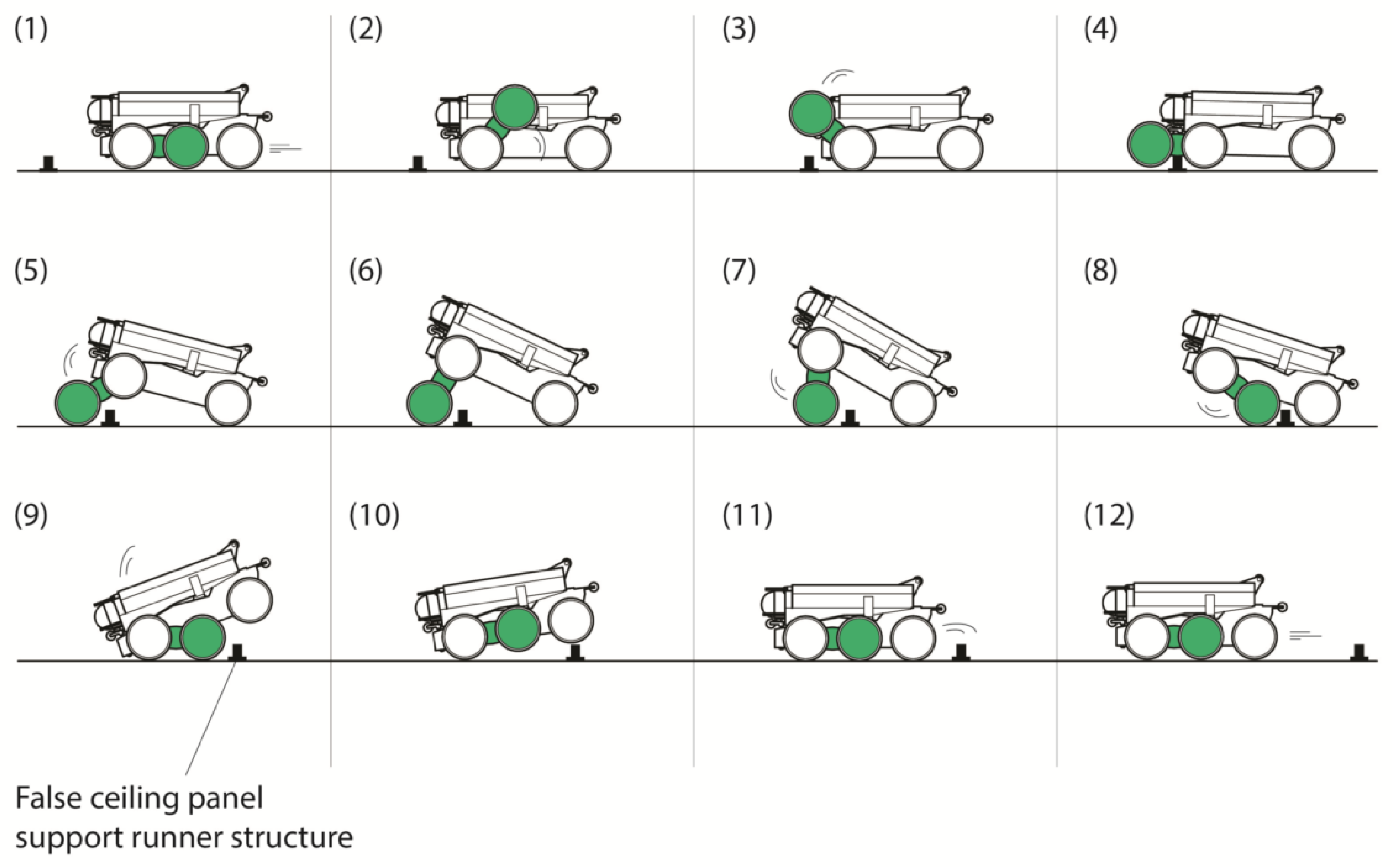
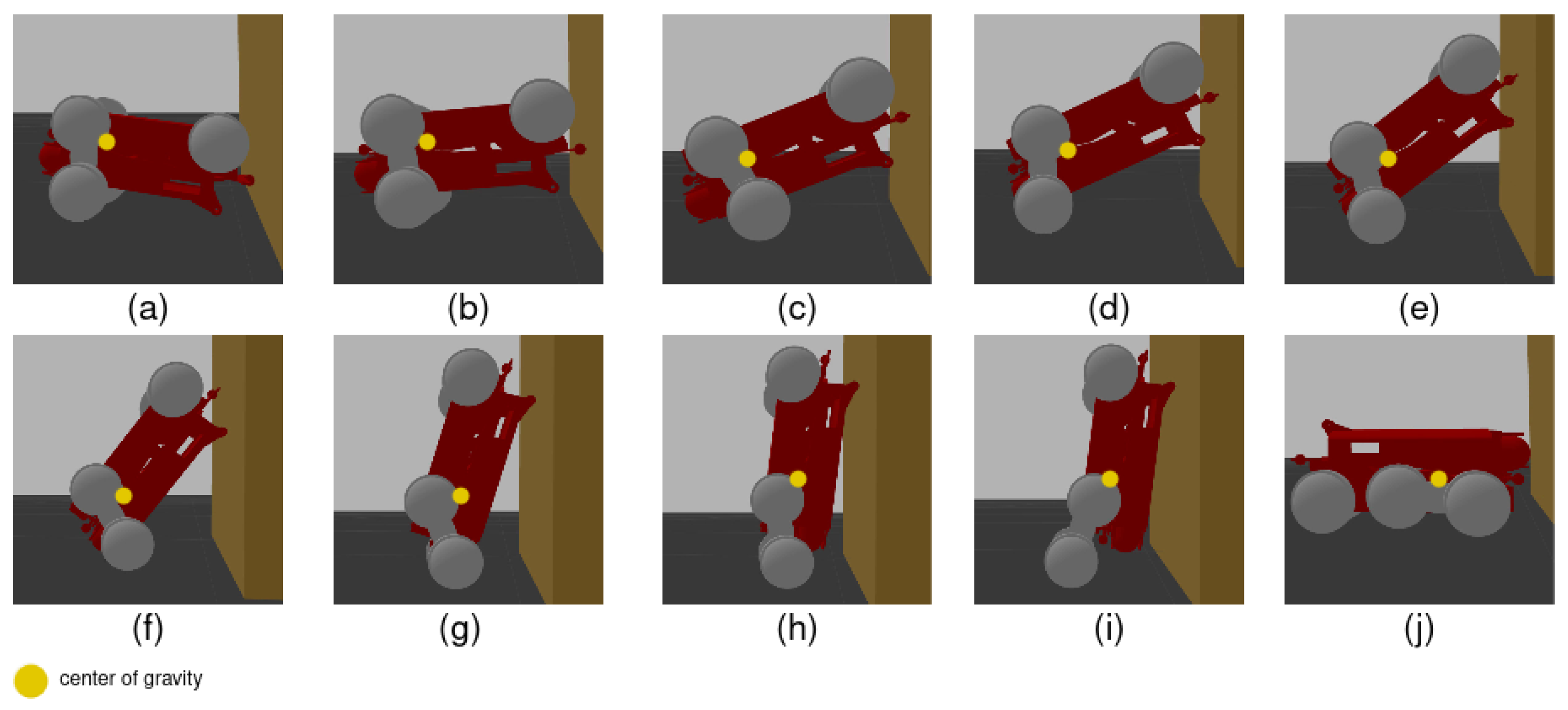
4.1. Scenarios Where Robot Falls onto Its Side

Rounded wheel caps mitigated scenarios where the robot would be stuck on its side. These rounded wheel caps enabled the robot to roll on its side compared to the conditions where they were kept flat. This modification enabled the robot to recover even when toppled onto its side, as seen in Figure 9b, when the rotary wheels were used to prop the robot onto its back and continue moving with the rotary wheels and top support wheel. θ 3 is 12°. The offsetting from the robot’s CG caused rotation along the rounded wheel cap as the pivot point, leading to the robot rolling over onto its back, where it could utilise the recovery process whereby the robot self-rights upon toppling onto its back.
Further toppling was addressed by getting the robot to roll onto its back using the customised shell design. The rotary wheels were then used to form a three-point contact with the top support wheel and move upside down with the two rotary wheels and the top support wheel. Afterwards, the rotary wheels were then able to move the robot towards a vertical plane (such as the walls or dividers within the false ceiling) for it to pivot and flip over back to its neutral position, as described in the previous subsection whereby the robot can flip onto its back.

4.2. Scenarios Where Robot Falls onto Its Back Edge

In cases where the robot is tilted backwards, the robot uses the back bumper wheels and falls back to its neutral position due to the offset centre of gravity, as seen in Figure 9c. Angle θ 4 is 3°, with the offset CG causing the robot to fall back to its neutral position. The rotary wheels helped in pushing the robot up from other obstacles and enable the robot to move if needed.

4.3. Scenarios Where Robot Falls onto Its Front Edge

For cases where the robot is tilted forwards (such as driving into a gutter or depression) within a false ceiling plenum, the front bumper wheel arrests further movement and the robot can recover by reversing and using the rotary wheels as leverage, as seen in Figure 9d, where angle θ 5 is 72°.

4.4. Scenarios Where Robot Is Flipped Upside Down
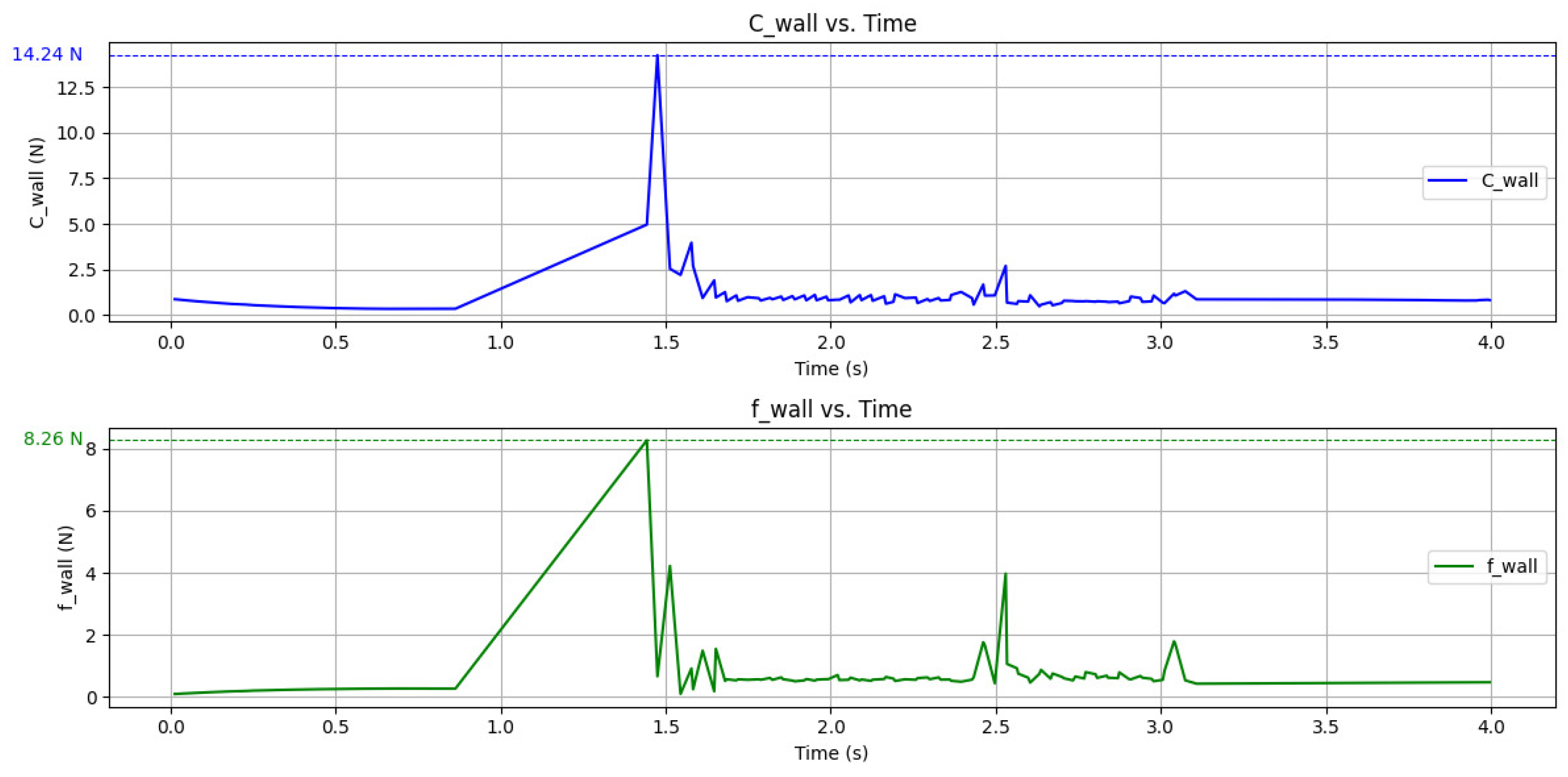
For self-righting scenarios, the modifications enable the robot to self-right after being flipped upside down, with the curvature of the top shell preventing the robot from being stuck on its back. The low height of the storage shell enables the robot’s rotary wheels to contact the ground when raised perpendicularly from the robot body. The robot is thus able to move upside down to a vertical surface to pivot and flip itself over.
The robot model was simulated in Gazebo to use a vertical surface as leverage to self-right from a flipped-over position, as seen in Figure 10. The environment setup in Gazebo is shown in Table 2. The robot formed a three-point contact with the ground with the rotary wheels and top support wheel. The initial jump-start from a stationary position jerked the back edge of the robot upwards to contact the vertical surface with the support wheels. After contacting the vertical surface as seen in Figure 10a, the robot needed T l i m i t to push itself up and leverage the vertical surface to flip it the right side up. The force values of simulated C w a l l and f w a l l are shown in Figure 11, showing the contact force changes as the robot first contacted the wall surface.
This process was validated by having the actual robot pivot itself over using a wall and flip back to its neutral position with the proposed method, as seen in Figure 12. This enabled the FalconX robot to flip itself back to its neutral position after being toppled for retrieval.
A further validation test was conducted at a false ceiling site above the SUTD lab. Figure 13 shows the self-righting process performed in actual site conditions.
Figure 13a,b show FalconX in position for self-righting, Figure 13c–e show the self-righting process, while Figure 13f–h show the robot returning to its neutral state for further inspection. This hence validates the self-righting method put forth in this paper.
The mechanical modifications and recovery methods thus help the robot in prolonging its ability to move and explore false ceiling areas. This is pertinent for cases where a robot has toppled in a false ceiling. The ability to self-right reduces the need for manual retrieval and re-deployment and lets the robot continue inspection tasks with minimal human intervention. Thus, FalconX can navigate and inspect false ceilings with the ability to self-right if toppled due to the new design compared to the previous Falcon model. The real-life results in Figure 12 validate the simulated results in Figure 10 and show that the findings, both simulated and actual, agree with each other.

4.5. Summary

A summary of the results is listed in Table 3.

5. Discussion

The recovery process would only fail in the fringe scenarios where the robot gets trapped in small niches or caught in spatial layouts that prevent the robot wheels from moving. This is also mitigated with the updated FalconX by preventing the robot from slipping through smaller gaps due to its size or going into spaces that it cannot reverse or move out of. In cases where the robot is unable to self-right after extensive motion of the rotary wheels, it will still require manual retrieval by a human operator. However, this form of robotic aid will still minimise the number of times a human operator is required to climb to access the false ceiling and be susceptible to fall risks and potential pathogen exposure.
As the experiments were conducted in the Gazebo program, a bottleneck was found in the model that was limited to rigid-body objects, which limited the modelling of the actual (albeit minute) flexibility of the different materials of the real-life robot. This issue could be solved if there are improvements to the modelling program in this aspect. The current mathematical model also adopted simplified assumptions, which may not fully represent the dynamic and complex interactions experienced during real-world recovery manoeuvrers. These assumptions were used to provide an analytical formulation for this problem. In real-world scenarios, the robot may benefit from momentum or inertial effects, making the required torque less than the theoretical amount. The static equilibrium can thus provide an upper-bound estimate for the required recovery torque.
Previous versions of Falcon robots were unable to perform self-righting, and that was the main reason for designing this robot: to mitigate cases where the previous robots would get trapped in a false ceiling when flipped over. Other robots with self-righting functions would be impractical to fit and operate within the typically tight and constrained false ceiling spaces.

6. Conclusions

This paper discussed and evaluated the key contributions of both creating and validating a virtual and actual self-righting mechanism implemented in the FalconX robot used in false ceiling inspection for deployment in actual false ceiling sites. These self-righting mechanisms and its force analysis diagram were presented, along with insights into its limitations due to simulation software constraints in terms of material flexibility for the virtual model and niche obstacle layouts in real-life false ceiling conditions. Upon toppling, the robot utilises its rotary-wheeled arms to land itself on its back. It then uses self-righting methods to flip itself over to be right side up using a vertical surface. The derived equations for determining the torque required for self-righting were expressed and analysed, along with the simulated and validated results in real life.
Future works would entail the addition of other sensors and end-effectors on the robot to detect other maintenance parameters such as humidity or polarised light. The detection add-ons would be needed for checking other parameters (such as using humidity sensors for plumbing leakage or polarised light for checking excessive stress or tension on support structures that cannot be viewed with just a visual camera) within the false ceiling plenum to further automate the inspection process. This information would help greatly in false ceiling rectification works. Considerations can be made in designing specialised sensor mounts for these sensors. The design would determine how FalconX could still self-right with the customised sensor mounts for expanded detection capabilities. A dynamic model can be further developed to make it more accurate for real-world deployments.

Author Contributions

Conceptualisation, M.S.K.Y., Z.Y. and R.E.M.; methodology, M.S.K.Y. and Z.Y.; software, Z.Y.; validation, M.S.K.Y. and Z.Y.; formal analysis, S.M.B.P.S.; investigation, M.S.K.Y. and Z.Y.; resources, R.E.M.; data curation, S.M.B.P.S.; writing—original draft preparation, M.S.K.Y. and Z.Y.; writing—review and editing, S.M.B.P.S.; visualisation, M.S.K.Y. and Z.Y.; project administration, R.E.M.; funding acquisition, R.E.M. All authors have read and agreed to the published version of the manuscript.

Funding

This research was supported by the National Robotics Programme under its National Robotics Programme (NRP) BAU, Ermine III: Deployable Reconfigurable Robots, Award No. M22NBK0054, and by A*STAR under its “RIE2025 IAF-PP Advanced ROS2-native Platform Technologies for Cross sectorial Robotics Adoption (M21K1a0104)” programme.

Institutional Review Board Statement

Not applicable.

Informed Consent Statement

Not applicable.

Data Availability Statement

No new data were created or analysed in this study. Data sharing is not applicable to this article.

Conflicts of Interest

The authors declare no conflicts of interest.

References

  1. Sullivan, C.; Horwitz-Bennett, B. Ceiling Designs. 2021. Available online: https://www.bdcuniversity.com/sites/sgc-university/files/AIA_BDC0213.pdf (accessed on 20 January 2025).
  2. Cha, S.H.; Koo, C.; Kim, T.W.; Hong, T. Spatial perception of ceiling height and type variation in immersive virtual environments. Build. Environ. 2019, 163, 106285. [Google Scholar] [CrossRef]
  3. Hu, Z.Z.; Zhang, J.P.; Yu, F.Q.; Tian, P.L.; Xiang, X.S. Construction and facility management of large MEP projects using a multi-Scale building information model. Adv. Eng. Softw. 2016, 100, 215–230. [Google Scholar] [CrossRef]
  4. Beddu, S.; Zainoodin, M.M.; Muda, Z.C.; Kamal, N.L.M.; Mohamad, D.; Nazri, F.M.; Naganathan, S.; Husain, N.M.; Sadon, S.N. Investigation of Natural Fibers as Ceiling Material. In Proceedings of the AWAM International Conference on Civil Engineering, Penang, Malaysia, 21–22 August 2019; pp. 1239–1244. [Google Scholar]
  5. Michael, M.; Sankar, V.; Paul, A.; Joy, A.; Fainusa, V.; Raju, C.I. Comparative study on the effect of false ceiling materials on the room temperature. In Green Buildings and Sustainable Engineering; Springer: Berlin/Heidelberg, Germany, 2019; pp. 179–187. [Google Scholar]
  6. Kruger, K. The Effect of Various Parameters on the Sound Isolation between Offices with Suspended Ceilings. Can. Acoust. 1988, 16, 9. [Google Scholar]
  7. Manglani, P.; Dee, R.; McHugh, J.; Heschong, L. Best Practices for Designing Modular Skylight Systems with Suspended Ceilings. PIER Integrated Ceilings Project. 2003. Available online: https://www.aceee.org/files/proceedings/2004/data/papers/SS04_Panel3_Paper18.pdf (accessed on 20 January 2025).
  8. Tan, C.Y. Advisory on Good Practices for the Inspection and Maintenance of Suspended Ceilings. 2021. Available online: https://www1.bca.gov.sg/docs/default-source/docs-corp-news-and-publications/circulars/good-practices-for-the-inspection-and-maintenance-of-suspended-ceilings.pdf (accessed on 22 January 2025).
  9. Min, J.; Kim, Y.; Lee, S.; Jang, T.W.; Kim, I.; Song, J. The fourth industrial revolution and its impact on occupational health and safety, worker’s compensation and labor conditions. Saf. Health Work 2019, 10, 400–408. [Google Scholar] [CrossRef]
  10. Koh, K.H.; Farhan, M.; Yeung, K.P.C.; Tang, D.C.H.; Lau, M.P.Y.; Cheung, P.K.; Lai, K.W.C. Teleoperated service robotic system for on-site surface rust removal and protection of high-rise exterior gas pipes. Autom. Constr. 2021, 125, 103609. [Google Scholar] [CrossRef]
  11. Agnisarman, S.; Lopes, S.; Madathil, K.C.; Piratla, K.; Gramopadhye, A. A survey of automation-enabled human-in-the-loop systems for infrastructure visual inspection. Autom. Constr. 2019, 97, 52–76. [Google Scholar] [CrossRef]
  12. Nitta, Y.; Inai, S.; Matsumura, K.; Ishida, M.; Onai, T.; Nishitani, A. The visual inspection methodology for ceiling utilizing the blimp. Procedia Eng. 2017, 188, 256–262. [Google Scholar] [CrossRef]
  13. Ko, H.; Yi, H.; Jeong, H.E. Wall and ceiling climbing quadruped robot with superior water repellency manufactured using 3D printing (UNIclimb). Int. J. Precis. Eng. Manuf.-Green Technol. 2017, 4, 273–280. [Google Scholar] [CrossRef]
  14. Zhang, Y.; Dodd, T.; Atallah, K.; Lyne, I. Design and optimization of magnetic wheel for wall and ceiling climbing robot. In Proceedings of the 2010 IEEE International Conference on Mechatronics and Automation, Singapore, 28–30 June 2010; pp. 1393–1398. [Google Scholar]
  15. Selvakumaran, S.; Hayat, A.; Elangovan, K.; Manivannan, K.; Elara, M. Design of a Self-reconfigurable Robot with Roll, Crawl, and Climb Features for False Ceiling Inspection Task. In Robotics, Control and Computer Vision: Select Proceedings of ICRCCV 2022; Springer: Berlin/Heidelberg, Germany, 2023; pp. 467–477. [Google Scholar]
  16. Kessens, C.C.; Smith, D.C.; Osteen, P.R. A framework for autonomous self-righting of a generic robot on sloped planar surfaces. In Proceedings of the 2012 IEEE International Conference on Robotics and Automation, St Paul, MN, USA, 14–18 May 2012; pp. 4724–4729. [Google Scholar]
  17. Johnson, A.M.; Libby, T.; Chang-Siu, E.; Tomizuka, M.; Full, R.J.; Koditschek, D.E. Tail assisted dynamic self righting. In Adaptive Mobile Robotics; World Scientific: Singapore, 2012; pp. 611–620. [Google Scholar]
  18. Casarez, C.S.; Fearing, R.S. Dynamic terrestrial self-righting with a minimal tail. In Proceedings of the 2017 IEEE/RSJ International Conference on Intelligent Robots and Systems (IROS), Vancouver, BC, Canada, 24–28 September 2017; pp. 314–321. [Google Scholar]
  19. Chen, K.; Chen, D.; Zhang, Z.; Wang, M. Jumping robot with initial body posture adjustment and a self-righting mechanism. Int. J. Adv. Robot. Syst. 2016, 13, 127. [Google Scholar] [CrossRef]
  20. Zhang, J.; Song, G.; Li, Z.; Qiao, G.; Sun, H.; Song, A. Self-righting, steering and takeoff angle adjusting for a jumping robot. In Proceedings of the 2012 IEEE/RSJ International Conference on Intelligent Robots and Systems, Vilamoura-Algarve, Portugal, 7–12 October 2012; pp. 2089–2094. [Google Scholar]
  21. Jani, N.K. Study of False Ceiling Design and Execution Process; Research and Publications Department, National Institute of Construction Management and Research: Pune, India, 2019; p. 296. [Google Scholar]
  22. Yeo, M.S.K.; Samarakoon, S.M.B.P.; Ng, Q.B.; Ng, Y.J.; Muthugala, M.A.V.J.; Elara, M.R.; Yeong, R.W.W. Robot-Inclusive False Ceiling Design Guidelines. Buildings 2021, 11, 600. [Google Scholar] [CrossRef]
  23. Horodinca, M.; Doroftei, I.; Mignon, E.; Preumont, A. A simple architecture for in-pipe inspection robots. Proc. Int. Colloq. Mobile Auton. Syst. 2002, 61, 64. [Google Scholar]
  24. Kroll, A. A survey on mobile robots for industrial inspection. In Proceedings of the International Conference on Intelligent Autonomous Systems IAS10, Baden-Baden, Germany, 15 July 2008; pp. 406–414. [Google Scholar]
  25. Verma, A.; Kaiwart, A.; Dubey, N.D.; Naseer, F.; Pradhan, S. A review on various types of in-pipe inspection robot. Mater. Today Proc. 2022, 50, 1425–1434. [Google Scholar] [CrossRef]
  26. Halder, S.; Afsari, K. Robots in inspection and monitoring of buildings and infrastructure: A systematic review. Appl. Sci. 2023, 13, 2304. [Google Scholar] [CrossRef]
  27. Lattanzi, D.; Miller, G. Review of Robotic Infrastructure Inspection Systems. J. Infrastruct. Syst. 2017, 23, 04017004. [Google Scholar] [CrossRef]
  28. Ma, W.; Li, B.; Jiang, L.; Wu, Y.; Bai, R.; Chen, G. A Soft, Centimeter-Scaled, Thin-Cable-Crawling Robot for Narrow Space Inspection. Adv. Intell. Syst. 2024, 6, 2300828. [Google Scholar] [CrossRef]
  29. Cheah, W.; Groves, K.; Martin, H.; Peel, H.; Watson, S.; Marjanovic, O.; Lennox, B. MIRRAX: A reconfigurable robot for limited access environments. IEEE Trans. Robot. 2022, 39, 1341–1352. [Google Scholar] [CrossRef]
  30. Khan, M.B.; Chuthong, T.; Danh Do, C.; Thor, M.; Billeschou, P.; Larsen, J.C.; Manoonpong, P. iCrawl: An Inchworm-Inspired Crawling Robot. IEEE Access 2020, 8, 200655–200668. [Google Scholar] [CrossRef]
  31. Leggieri, S.; Canali, C.; Caldwell, D.G. Design, modeling, and experimental analysis of the Crawler Unit for inspection in constrained space. Annu. Rev. Control 2024, 57, 100950. [Google Scholar] [CrossRef]
  32. Ciszewski, M.; Giergiel, M.; Buratowski, T.; Małka, P. Modeling and Control of a Tracked Mobile Robot for Pipeline Inspection; Springer: Berlin/Heidelberg, Germany, 2020. [Google Scholar]
  33. Koh, K.; Choi, H.; Kim, J.S.; Ko, K.W.; Cho, H. Sensor-based navigation of air duct inspection mobile robots. Optomechatronic Syst. 2001, 4190, 202–211. [Google Scholar]
  34. Filipek, P.; Kamiński, T. Remote controlled mobile inspection robot. J. KONES 2011, 18, 129–135. [Google Scholar]
  35. Ab Rashid, M.Z.; Mohd Yakub, M.F.; Zaki bin Shaikh Salim, S.A.; Mamat, N.; Syed Mohd Putra, S.M.; Roslan, S.A. Modeling of the in-pipe inspection robot: A comprehensive review. Ocean Eng. 2020, 203, 107206. [Google Scholar] [CrossRef]
  36. Parween, R.; Wen, T.Y.; Elara, M.R. Modelling and Analysis of a Vertical Wall Robot for Ceiling Inspection. In Proceedings of the 2022 IEEE 12th Annual Computing and Communication Workshop and Conference (CCWC), Virtual, 26–29 January 2022; pp. 0679–0687. [Google Scholar]
  37. Scalise, R.; Caglar, E.; Boots, B.; Kessens, C.C. Toward Self-Righting and Recovery in the Wild: Challenges and Benchmarks. In Proceedings of the 2024 IEEE International Conference on Robotics and Automation (ICRA), Yokohama, Japan, 13–17 May 2024; pp. 15329–15335. [Google Scholar]
  38. King, K.; Revzen, S. Self-Righting Shell for Robotic Hexapod. In Proceedings of the 2024 IEEE International Conference on Robotics and Automation (ICRA), Yokohama, Japan, 13–17 May 2024; pp. 1436–1442. [Google Scholar]
  39. Teder, E.; Chong, B.; He, J.; Wang, T.; Iaschi, M.; Soto, D.; Goldman, D.I. Effective self-righting strategies for elongate multi-legged robots. arXiv 2024, arXiv:2410.01056. [Google Scholar]
  40. Li, C.; Kessens, C.C.; Young, A.; Fearing, R.S.; Full, R.J. Cockroach-inspired winged robot reveals principles of ground-based dynamic self-righting. In Proceedings of the 2016 IEEE/RSJ International Conference on Intelligent Robots and Systems (IROS), Daejeon, Republic of Korea, 9–14 October 2016; pp. 2128–2134. [Google Scholar]
  41. Qian, J.; Cheng, W.; He, Y.; Su, J.; Zhang, Y. A novel mobile robot with a backbone for self up-righting capability. In Proceedings of the 2000 IEEE/RSJ International Conference on Intelligent Robots and Systems (IROS 2000) (Cat. No.00CH37113), Takamatsu, Japan, 31 October–5 November 2000; Volume 3, pp. 2224–2229. [Google Scholar]
  42. Muthugala, M.V.J.; Apuroop, K.G.S.; Padmanabha, S.G.A.; Samarakoon, S.B.P.; Elara, M.R.; Wen, R.Y.W. Falcon: A false ceiling inspection robot. Sensors 2021, 21, 5281. [Google Scholar] [CrossRef] [PubMed]
  43. Semwal, A.; Mohan, R.E.; Melvin, L.M.J.; Palanisamy, P.; Baskar, C.; Yi, L.; Pookkuttath, S.; Ramalingam, B. False ceiling deterioration detection and mapping using a deep learning framework and the teleoperated reconfigurable ‘Falcon’Robot. Sensors 2021, 22, 262. [Google Scholar] [CrossRef]
  44. Pathmakumar, T.; Sivanantham, V.; Anantha Padmanabha, S.G.; Elara, M.R.; Tun, T.T. Towards an optimal footprint based area coverage strategy for a false-ceiling inspection robot. Sensors 2021, 21, 5168. [Google Scholar] [CrossRef]
  45. Shanmugam, P. Reminder on Good Practices for Design and Installation of Suspended Ceiling Works. BCA. 2018. Available online: https://www1.bca.gov.sg/docs/default-source/docs-corp-news-and-publications/circulars/reminder-on-adoption-of-good-practices-for-design-and-installation-of-suspended-ceilings.pdf (accessed on 22 January 2025).
Figure 1. Left: Scenario where the tracked version of Falcon gets trapped due to its design, i.e., its inability to move when suspended in the middle section. Right: Example of a previous version of Falcon robot getting stuck due to an orientation, obstacle and form factor.
Applsci 15 04616 g001
Figure 2. FalconX robot: (a) top view; (b) axonometric view showing key robot parts. The FalconX robot has a front-facing camera and moves along using six wheels. Two of the wheels (one on each side) are connected to rotary arms that rotate around the front set of wheels to pull the robot over obstacles or help in self-righting the robot. The curved top shell reduces the possibility of the robot getting stuck in an upside down position without the proper orientation of rotary wheels to self-right.
Applsci 15 04616 g002
Figure 3. Main dimensions of FalconX robot.
Applsci 15 04616 g003
Figure 4. FalconX using its rotary wheels to overcome low-height obstacles. Upon encountering a low-height obstacle, the rotary arms are lifted over the obstacle (15). The rotary arms are then used to pull the main body of the robot over the low-height obstacle (69). Once the robot passes over the obstacle, the rotary arms are returned to the original position (1012) and the FalconX robot can continue its inspection tasks.
Applsci 15 04616 g004
Figure 5. Form factor extending beyond wheeled base boundary; angles of first contact when toppled along front and back shown by the red lines, θ 1 is 26°, θ 2 is 74°. Red point represents the robot’s centre of gravity.
Applsci 15 04616 g005
Figure 6. (a) State of toppled robot before conducting self-righting procedure. (b) Robot jump-starts from stationary position and contacts wall to perform self-righting.
Applsci 15 04616 g006
Figure 7. Diagram of flipped robot in position and the forces required for a jump-start to achieve the ideal self-righting position. The blue dot represents the robot’s approximate centre of gravity. P is noted to be approximately 25°.
Applsci 15 04616 g007
Figure 8. Parameters used in modelling robot behaviour for self-righting from upside down position; m is the robot’s mass, g is the gravitational constant, r is the robot wheel radius, H is the vertical height from the top support wheel contact point with the wall to the ground plane, H 3 is the vertical height of the centre of mass from the ground plane, μ is the frictional coefficient between the wall and support wheel, A is the robot’s wheel contact point with the ground plane, and w is the horizontal distance between the centre of the rotary wheel and the vertical wall. The red dot represents the robot’s center of gravity. The diagram shows the robot in the process of scaling the wall to self-right.
Applsci 15 04616 g008
Figure 9. Diagram showing FalconX robot: (a) angles of first contact; (b) angle of tilt from robot’s centre of gravity when fallen onto its side; (c) angle of tilt for self-righting when toppled backwards; (d) angle of tilt for self-righting when toppled forwards. The red dot represents the robot’s center of gravity. Pivot points are the robot’s contact points with the ground plane and are labelled by black dots. Further explanation for each mode of toppling are described in the respective subsections.
Applsci 15 04616 g009
Figure 10. Simulation of self-righting robot in Gazebo; robot’s centre of gravity (CG) denoted by yellow point. (ac): Model robot in preparation for self-righting; (di): Model robot in process of self-righting; (j) Model robot self-righted to neutral position.
Applsci 15 04616 g010
Figure 11. Graph of C w a l l and f w a l l values simulated by robot upon initial contact with vertical wall in Gazebo; collision values of 14.24 N for C w a l l and 8.26 N for f w a l l were recorded.
Applsci 15 04616 g011
Figure 12. Recovery method with actual FalconX robot by pivoting off a vertical wall. Robot’s approximate centre of gravity shown by orange point; ground pivot point shown using blue points. (a): Robot in self-righting pose; (bf): conducts flip to self-right itself; (gh): returning to neutral state.
Applsci 15 04616 g012
Figure 13. Recovery method with actual FalconX robot validated in false ceiling settings above SUTD lab. (a): robot in preparation of self-righting; (be): Robot in process of self-righting; (fh): Robot realigning rotary wheels to neutral position for further inspection.
Applsci 15 04616 g013
Table 1. Step-by-step explanation and computation of required torque for jump-start motion.
ExplanationFormulaCalculation with Values
1. Horizontal distance between contact point and CG w = w 2 cos P 0.065 cos ( 25 deg ) = 0.0589  m
2. Vertical distance between contact point and CG h = w 2 2 + h 2 2 sin ( arctan ( h 2 w 2 ) + P ) 0 . 065 2 + 0 . 045 2 sin ( arctan ( 0.045 / 0.065 ) + 25 deg ) = 0.0592 m
3. Torque balance at contact pointT + mg w′ − f h′ = 0
4. Frictional torque relationT = f r
5. Solve for friction force f f = m g w h r 0.576 9.81 0.0589 0.0592 0.025 = 9.74 N
6. Final required torqueT = f r9.74 ∗ 0.025 = 0.2435 Nm
Table 2. Setup parameters in Gazebo simulation.
ComponentDescription
Robot modelFalconX robot (a URDF file)
WallA cube (1.0 × 1.0 × 1.0 m), mass = 10 kg
Static friction coefficient of the wall1.0
Sliding friction coefficient of the wall0.8
Physics engineOpen Dynamics Engine (ODE)
Table 3. Summary of robot fall scenarios and corresponding recovery mechanisms.
ScenarioRecovery MechanismKey Features
Falls onto its sideRounded wheel caps allow rolling to back; rotary wheels and top support wheel form 3-point contact to let the robot flip upright using vertical surface. θ 3 = 12 ° , offset CG enables roll
Falls onto its back edgeOffset CG causes natural fall to neutral position; rotary wheels help in further motion or overcoming obstacles. θ 4 = 3 ° , offset CG helps recovery
Falls onto its front edgeFront bumper wheel stops forwards motion; the robot uses rotary wheels as leverage to reverse. θ 5 = 72 ° , uses reverse + rotary wheels
Flipped completely upside downCurved top shell and low storage height allow rotary wheels to touch ground; robot moves to vertical surface, pivots and flips upright.rotary wheel to support, T l i m i t f g r d r = m g W 3 r H ( 1 μ tan θ )
Disclaimer/Publisher’s Note: The statements, opinions and data contained in all publications are solely those of the individual author(s) and contributor(s) and not of MDPI and/or the editor(s). MDPI and/or the editor(s) disclaim responsibility for any injury to people or property resulting from any ideas, methods, instructions or products referred to in the content.

