Article

Research on Overburdened Rock Structures and Support Resistance of Shallow Buried Large Mining Heights Based on Sheet Gangs

by
Pei Zhang
1,2,*,
Yang Chen
1,2,
Yibo Wei
1,2,
Zhuo Li
1,2 and
Liqiang Dong
1,2
1
School of Energy and Mining Engineering, Xi’an University of Science and Technology, Xi’an 710054, China
2
Key Laboratory of Mine Mining and Disaster Prevention in West China, Ministry of Education, Xi’an University of Science and Technology, Xi’an 710054, China
*
Author to whom correspondence should be addressed.
Appl. Sci. 2025, 15(9), 4730; https://doi.org/10.3390/app15094730
Submission received: 8 March 2025 / Revised: 18 April 2025 / Accepted: 22 April 2025 / Published: 24 April 2025

Abstract

:
In the mining of shallow coal seams, the increase in mining height will lead to a sharp increase in the probability and degree of coal wall spalling. Rib spalling will affect the normal production of coal mines and may also threaten the safety of miners. Under the state of coal wall ganging in large mining height working faces, determining the working face’s support resistance is a key engineering problem that involves many factors, such as bracket design, the mechanical behavior of the roof rock layer, coal wall stability, and so on. In this paper, (1) the relationship between coal wall pressure and working face support resistance is analyzed by constructing a mechanical model of roof control in the large height mining field, (2) and four roof structure models are established based on the single and double key layer structures of step rock beams in shallow buried coal beds. (3) The calculation methods of working face support resistance after coal wall sheet ganging under the four structural models are deduced. Determining the working face’s support resistance is the key to solving the problem of coal wall ganging in large height working faces, which has a significant impact on the design of bracing, the mechanical behavior of the roof rock layer, and coal wall stability.

1. Introduction

Shallow coal seams are common in western China, and thick coal seams are rich in reserves. Large mining height has become the main mining technology for such coal seams. However, with the increase in mining height, support resistance increases, the coal wall’s spalling becomes more and more serious, and the strata’s control faces new challenges [1].
Stope support is the main means of roof control. The support resistance parameters of the support are divided into initial support force and rated working resistance. Determining reasonable support resistance is an important basis for support selection. The roof structure of shallow buried large mining height working faces has a new form, and the size of support resistance is related to the roof structure and the support mode. According to the relevant statistical data, the incidence of support surrounding rock accidents in large mining height comprehensive coal mining faces is several times that of general comprehensive coal mining faces [2].
The prevention and control of coal wall spalling has become an important issue in the development of technology. Only by mastering its causes can the advantages of this technology be better brought into play. Yin Xiwen et al. [3] used the compression bar theory to analyze the deflection characteristics of the coal wall with good integrity, and they obtained the position where the coal wall is prone to spalling in the middle and upper part of the coal wall. Yang Kun et al. [4] analyzed the influence of mining height and the position of the support guard plate on the roof caving step, shape, and coal wall failure depth and established the mechanical model of coal wall sliding failure. Ni Xianjie [5] studied the characteristics of coal wall spalling in fully mechanized mining faces with large mining heights. Ning Yu [6] and Yan Shaohong [7] studied the mechanism and control technology of coal wall spalling and roof falls in fully mechanized mining faces with large mining heights. Behera, B et al. [8] studied the mechanism of face instability and associated spalling. The critical strain limit of face instability was proposed. Design criteria were proposed for the three-dimensional quantification of face spalling. Pertinent rock mechanic indicators of face spalling were comprehensively discussed. Yuan Yong [9] systematically studied the stability control mechanism of support-surrounding rocks in fully mechanized mining faces with large mining heights. Wang Jiachen [10] and Kong Dezhong [11] studied the determination of support resistance controlled by the roof and the coal wall. Derrick Chambers et al. [12] studied coal wall bursting under longwall mining due to undercutting under sheet-roofing. Mohammad Reza Soleimanfar et al. [13] treat rock properties as spatially correlated random variables to enhance the accuracy of rock strength assessments and to improve the safety of mining operations through a robust stochastic modeling approach. Shang Yuqi et al. [14], aiming at the problems of roof falls and gangue leakage in working faces caused by surrounding rock failure in close-distance coal seam mining, theoretically analyzed the influence of mining height and the stress concentration coefficient on floor failure depth. Huang Qingxiang et al. [15] divided the shallow coal seam group into a single key stratum and a double key stratum. The roof structure model of lower coal seam mining was established, and the calculation method of support resistance of the working face was given. However, the calculation of support resistance in working faces will be affected by many factors and complex geological environments. The above scholars have not combined rib spalling, the immediate roof structure, and the key stratum structure for macro analysis. In this paper, the support resistance of shallow buried large mining height overburdened structures based on rib spalling is further studied.
The damage process of the coal body shows typical progressive characteristics. Initially, micro-fracture emergence is dominant, and as the stress continues to be loaded, the fracture expands along the direction of the maximum principal stress, and they penetrate into each other. Experiments show that when fracture density reaches the critical threshold, the risk of local coal wall instability rises sharply [16]. In a mine in Yulin, Shaanxi Province, for example, the fracture expansion rate of the coal wall in a working face with a mining height of 7.2 m was 32 mm per hour, and a penetrating rupture surface with a depth of 2.4 m was formed within 48 h, which ultimately triggered large-scale ganging and led to an increase in the deviation coefficient of the top beam load of the stent from 0.18 to 0.47. Furthermore, the deflection rate of the column was up to 28% [17]. The sustained development of gangs will trigger multiple disaster chain reactions. (1) Roof instability: gangs lead to an increase in the distance between empty roofs at the end face (for every increase of 0.5 m, the amount of roof subsidence rises by 12–15%), and the depth of gangs in a working face in the Shendong Mining Area is 3.1 m, which shortens the distance between the top plate cycle and the pressure step by 30% and increases the frequency of opening the safety valve of the stent by two times [18]. (2) Equipment damage: the impact load generated by the collapse of the coal wall (the peak value can be up to 1.5 times the working resistance of the bracket) can easily trigger column cylinder cracks, connecting pin fractures and other structural damage. In a mine in Huainan, the annual maintenance cost of this type of accident increased by CNY 15 million. (3) Production capacity constraints: the accumulation of broken coal in the rib spalling increases the blockage rate of the transportation system by 40%. The Tashan Coal Mine of Jinneng Holdings has reduced the daily average production capacity by 25% due to the rib spalling, and the economic loss per month exceeds 8 million yuan [19].
This study aims to solve the key problem of roof instability induced by coal wall ganging in shallow buried large mining height working faces, and the specific objectives include the following. 1. Establishing the classification model of roof structures after coal wall ganging. Aiming at the geological characteristics of single and double key seams in shallow buried coal seams and combining the theories of step rock beams and masonry beams [20], we put forward four types of structural models of roof slab–coal wall collaborative damage (single key layer Categories I and II and double key layer Categories I and II). 2. Derivation of the theory of dynamic calculation of support resistance. Based on the roof structure model, the coupling relationship between the depth l p of the sheet gang and the roof load is quantified, and the calculation formula of the support resistance considering the breakage angle of the rock layer ( α ), the rotation angle of the key block ( θ 1 ), and the coefficient of fracture expansion ( k p ) is constructed. 3. Validate the applicability of the model and propose optimization strategies, verify the accuracy of the model through the field data of typical mining areas in western China (Xialianta and Daliuta), analyze the threshold value of support resistance under different geological conditions, and propose an optimization scheme to dynamically regulate the matching of support resistance and mining height.
The specific realization methods are as follows. 1. Roof structure model construction (theoretical analysis): based on the key layer theory and rock beam articulation structure [21], a single/double key layer roof fracture mechanics model is established, and the concept of “step rock beam” is introduced to describe the discontinuous bearing behavior of the roof after fracture in shallow buried coal seams. 2. Classification basis: according to the combination of direct roof lithology (homogeneous/non-homogeneous) and the number of key layers (single/double), four types of roof structures are classified. 3. Derivation of mechanical equations of support resistance: the static equations of equilibrium are set up by taking the roof support–coal wall system as the object, and the impacts of the depth of sheet-help on the direct roof load and the additional load of the step rock beams are emphasized. 4. Parameter calibration: based on the measured data in the mining area of western China (e.g., the working face of Bulianta 32206), we determine the empirical parameters, such as the rock layer capacity, the crushing expansion coefficient, etc., and validate the range of values by quoting the industry standard (MT/T 592-2011). 5. Equation integration: we combine the bracket efficiency with the load transfer factor and derive the generalized equation of the four types of structural models for support resistance.

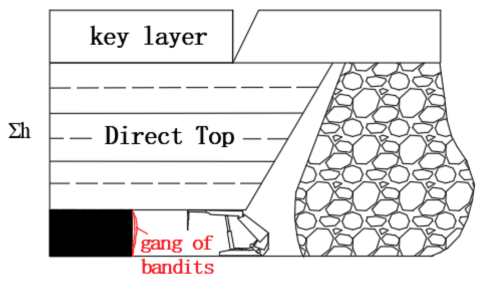
2. Top Plate Structure Under Coal Wall Sheet Ganging in Large Height Working Faces of Shallow Buried Coal Seams

The main reason for the strong pressure in the shallow coal seam is related to the composition of its key strata. The roof bedrock of the ordinary stope is thick, and there are multiple sets of key strata. The lower key strata closest to the stope are protected by the upper multiple sets of key strata, and they are in the decompression zone, so the stope pressure is not large. However, there are only one to two groups of key strata in the shallow coal seam, and the upper part of the key strata is a weak load layer until the surface. The roof’s structure is not easy to stabilize, resulting in rapid weighting. Therefore, according to the characteristics of key strata, shallow coal seams can be divided into two categories: typical shallow coal seams and near-shallow coal seams [22].
(1) Typical shallow coal seam. For shallow coal seams with thin bedrock and a thick loose load layer, the roof breaking movement is manifested in the form of overall cutting, which is prone to roof step subsidence. This kind of shallow buried coal seam with a thick loose layer and thin bedrock is called a typical shallow buried coal seam, which can be summarized as a coal seam with a shallow buried depth and a single key layer structure of the main roof.
(2) Near-shallow coal seam. For the shallow coal seam with relatively thick bedrock and a relatively thin loose load layer, the law of mine pressure behavior is between the ordinary working face and the shallow coal seam working face. The roof structure presents two groups of key layers, and there is a step sinking phenomenon, which can be called a near-shallow coal seam.
Based on the roof structure model of single and double key strata [23], this paper refers to the direct roof structure model [24] to establish the calculation model of key strata–direct roof combined support resistance in shallow coal seams.

Analysis of Direct Roof Structure Under Coal Wall Sheet Ganging in Large Height Working Faces of Shallow Buried Coal Seams

Field observation, simulation experiments, and theoretical derivation have consistently pointed out that [25] with the increase of mining height, the balanced structural rock strata in the large mining height area will move up, and the hinged balanced structure can be formed under the condition of conventional mining height, while in the case of large mining height, fractures will occur, and then collapse to the goaf. In this study, the strata that cannot form a balanced structure are defined as “immediate roof”. It can be seen that the thickness of the immediate roof in a large mining height stope is usually greater than that of conventional mining heights.
In general, the immediate roof thickness of large mining heights is 2.0 to 4.0 times its mining height [26], which indicates that it includes not only the rock strata that easily fall with mining but also the rock strata that are considered the basic roof in conventional mining heights. For example, when the mining height is 5.0 m, the thickness of the immediate roof may be between 10 and 20 m.
It can be seen that the composition of the immediate roof of the large mining height stope has changed compared with the immediate roof of the ordinary mining height, which will undoubtedly affect its load characteristics and force transmission mode. Gong Peilin classified the immediate roof into three types according to the composition of the overlying strata above the coal seam [27]. Because the type II immediate roof is characterized by a thick and fractured soft rock layer above the coal seam, it forms a direct roof together with the overlying hard rock layer. Due to the high height of the large mining height support, it is extremely difficult to deal with end face leakage, and large mining height technology is not suitable for this kind of condition. Therefore, according to the composition and structure of rock strata, this paper studies the large mining height immediate roof, which is divided into the following two categories.
(1) The first type of immediate roof is shown in Figure 1. Its characteristic is that the immediate roof above the coal seam is composed of the same lithology or different lithology but the mechanical difference is small.
(2) The second type of immediate roof is shown in Figure 2, which is characterized by the occurrence of one or two layers of thick strata with great strength and undeveloped fissures in the immediate roof. When the mining height is ordinary, the strata are equivalent to the “basic roof”, and when the mining height is large, the immediate roof is made.

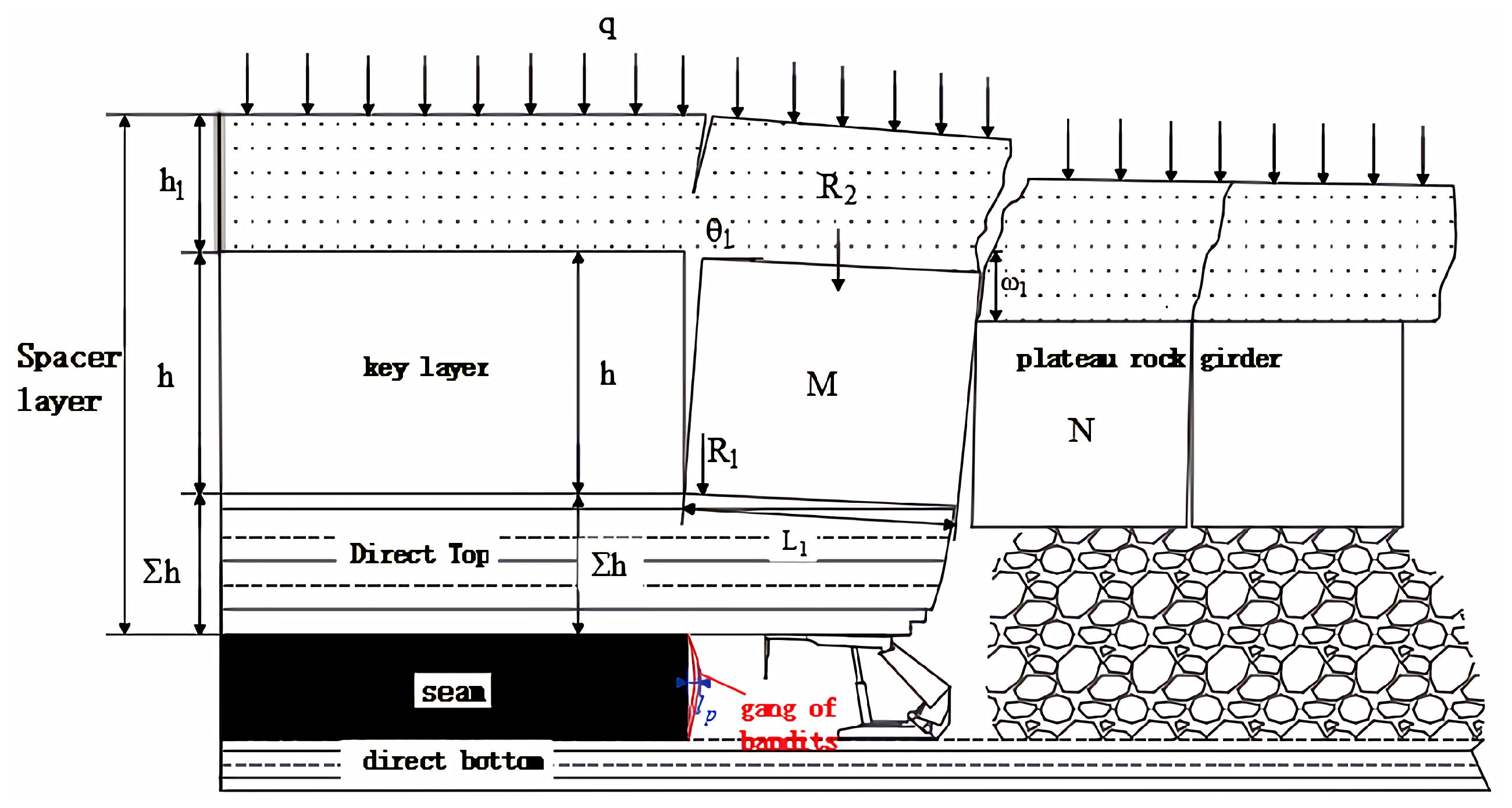
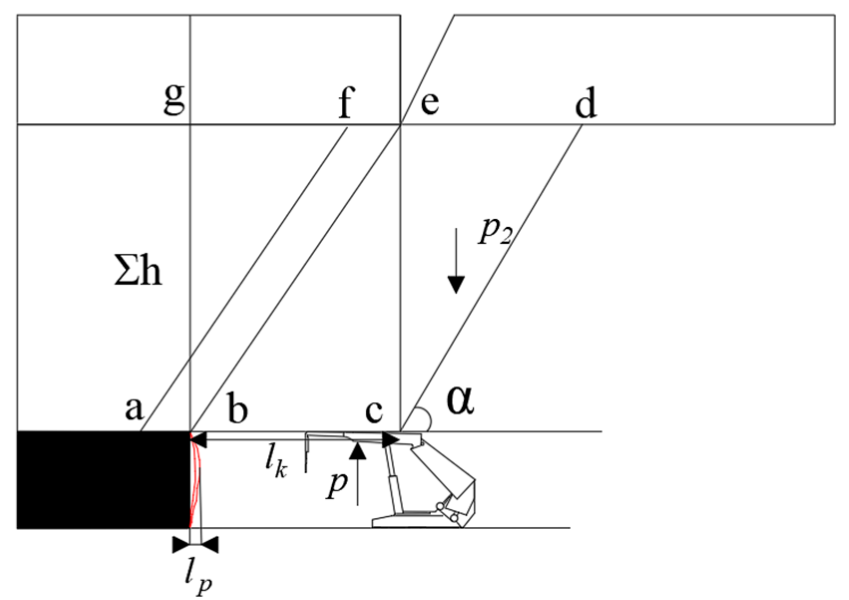
3. Calculation of the Support Resistance of a Large Height Sheet-Type Working Face Based on the “Step-Rock Beam” Structure

With the development of mining, the original stress balance of the overlying strata in the stope is destroyed, resulting in stress redistribution. The abutment pressure of the coal wall increases with the increase of the span of the basic roof, and the spalling of the coal wall is an important indicator of the roof pressure of the working face. With the continuous increase of mining height, the stability of the coal wall becomes worse, and the risk of coal wall spalling increases. This is an important subject of strata control in shallow coal seams when studying the structure of roof strata and the working resistance of support caused by spalling in shallow coal seams with large mining heights, which is of great academic significance to ensure safe and efficient mining of large mining heights [28].

3.1. Single Key Layer Category 1 Direct Top

3.1.1. Determination of Working Face Support Resistance Under a Single Key Layer Type I Direct Roof Structure

Based on the roof structure theory of typical shallow buried coal seams, the single key layer between the layers is broken to form a “step-rock beam” structure, and the caving roof above is simplified as a uniform load acting on the step rock beam structure. See Figure 3.
Bracket loads consist mainly of direct top loads and applied loads from the step rock beam structure. The support resistance of the brace is
P m = P + b R 1
where P m —bracket resistance due to direct top load; b —bracket width; and R 1 —sliding force of step rock beam M block.
Among them, the first type of direct top coal wall sheet gang working face support resistance calculation mechanical model is shown in Figure 4.
The direct top gravity is when the bracket load is considered according to the bceg rectangular area in Figure 4 and the sheet gang depth l p is taken into account:
P z = ( l k + l p ) γ α Σ h
where P z —direct top gravity; l k —control roof distance; l p —sheet gang depth; γ —direct top rock capacity weight; Σ h —direct top thickness; and α —rock breakage angle.
The bracket loads P 0 for the loading factor n [6] (In actual projects, a safety factor is usually set to ensure the safety of the supporting structure. The empirical formula shows that when the load coefficient is between 1.0 and 1.5, the support structure can effectively withstand the roof pressure and ensure the safety of the working face). The equation is
P 0 = n ( l k + l p ) γ α Σ h
Large mining heights are dominated by static loads n 1.5 when n = 1.5 and the coefficient of fragmentation and expansion k p = 1.3 ~ 1.5 . (According to Li Huamin [28], the coefficient of fragmentation and expansion is usually between 1.2 and 1.6 under similar geologic conditions. In the field experiments at Daliuta coal, the coefficient of fractional expansion was determined to be between 1.3 and 1.5) [29]:
p 0 = ( 3 5 ) M γ α ( l k + l p )
From the increased mining height, consider the gravity P 2 in the cde area in Figure 2, where Σ h is taken as (3~5) M (M is the mining height). The bracket load can be 3~5 times the mining height of the rock weight plus the end of the roof beam hanging to the corresponding thickness of the top gravity of the mining area, and a coefficient of 3~5 of the degree of incoming pressure is a comprehensive reflection of the actual mining height, which is not related or indirectly related. Selection should depend on analyzing the structure of the quarry and the degree of pressure. If the size of the basic top fracture step is large and the free space under it is large, then take the large value.
P 2 = 1 2 [ ( 3 ~ 5 ) M ] 2 γ α cot α
P = P 0 + P 2
According to the theory of the step rock beam structure in shallow buried coal seams [30], there are
R 1 = [ i sin θ 1 max + sin θ 1 0.5 i 2 sin θ 1 max + sin θ 1 ] P w
where P —bracket resistance due to direct top load; P m —bracing resistance caused by direct top load; R 1 —step rock beam M block sliding force; P w —step rock beam; M —block and its overburdened weight; i —step rock beam block degree; θ 1 —rotation angle of step rock beam M block; and θ 1 m a x —maximum angle of rotation of block M of the step rock beam.
P w consists of the step rock beam M block with load weight R 2 and the upper seam collapse roof load R 3 .
P w = R 2 + R 3
R 2 = ( h ρ g + h 3 ρ 1 g ) L 1
R 3 = L 1 q
where h 3 —height of the upper loading layer; ρ g —the capacitive weight of the step rock beam rock mass; ρ 1 g —the capacitive weight of the loading layer; and L 1 —step rock beam key block length.
Considering the support efficiency μ [31], the reasonable support resistance of the working face P 1 m is obtained from Equations (1)~(10):
P 1 m = b μ ( 3 ~ 5 ) M γ α ( l k + l p ) + 8 M γ α cot α b + L 1 ( i sin θ 1 max + sin θ 1 0.5 i 2 sin θ 1 max + sin θ 1 ) ( h ρ g + h 3 ρ 1 g + q )

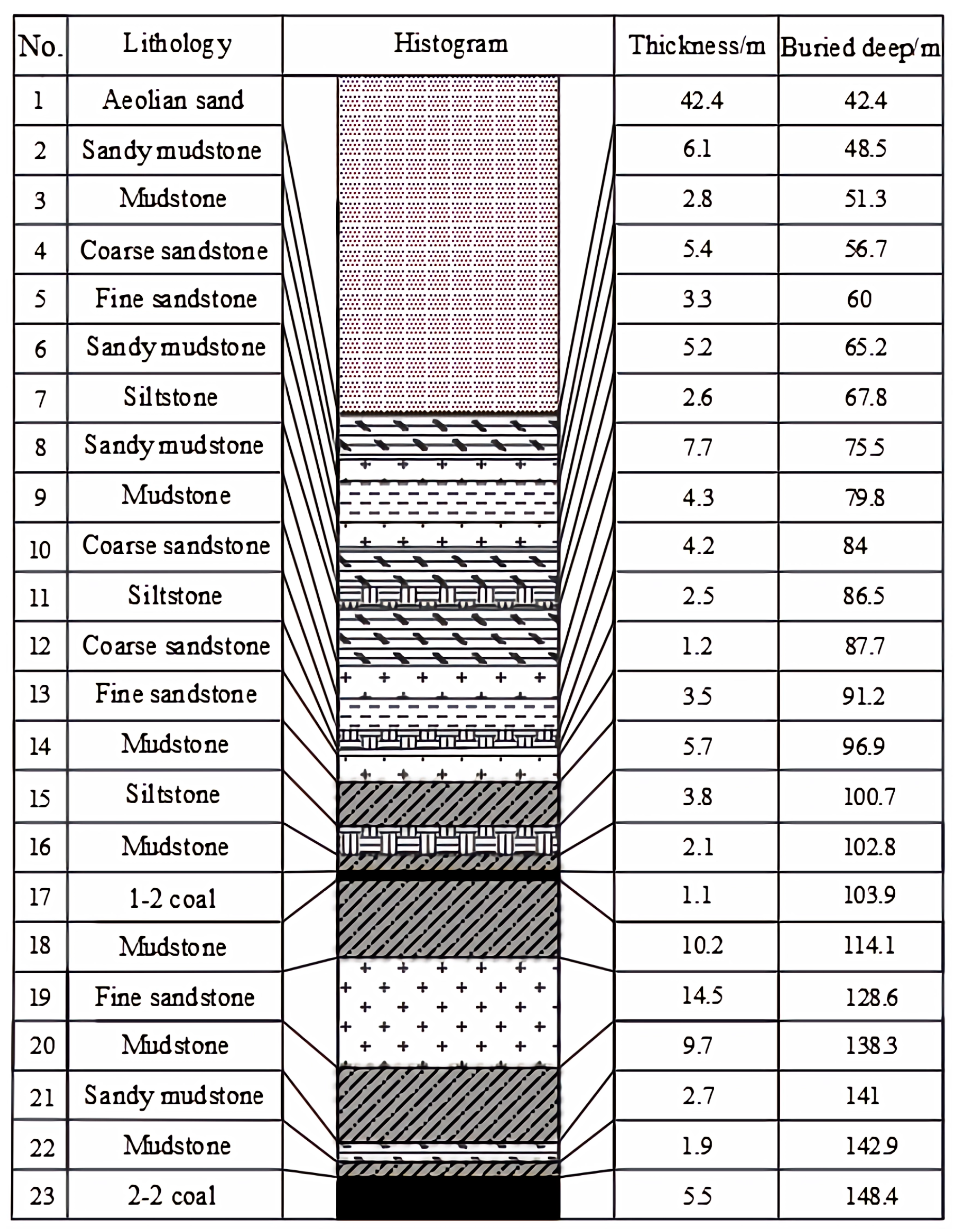
3.1.2. Instance Validation

For the supplementary Bulianta 32206 face mine, regarding the 2–2 coal seam, by arranging drill holes in the working face and the surrounding areas of the coal mine, detailed information regarding the coal and rock seams is obtained, and a comprehensive bar chart of the working face is drawn. With an average mining height of 5.5 m , a dip angle of 1 0 ~ 3 0 , and a burial depth of 145~155 m , the upper 1–2 upper coal has been mined with an average mining height of 1.1 m , an average spacing of 39 m between seams, and an inter-mining ratio of G = 7.1 . There is only one key stratum above the coal seam. The thickness of the key stratum is 14.5 m. The direct roof is below the key stratum, and the thickness of the direct roof is 14.3 m. The direct roof is composed of rock strata with the same lithology or different lithology but less mechanical difference, which conforms to the first type of immediate roof structure of a single key layer. The comprehensive histogram of the working face is shown in Figure 5.
According to the comprehensive column diagram of the working face of 32206, the mining conditions of the working face, and the breakage characteristics of the overlying rocks of the shallow buried coal seam, it can be seen that the support efficiency μ = 0.9, the width of the support b = 1.75   m , the distance of the top-control l k = 4.6   m , the depth of the slice of the gang l p = 1.05   m , and the distance of the cycle to the pressurized step l = 15.2   m . Direct top thickness Σ h = 14.3   m ; step rock beam key block length L 1 = 15.2   m ; key layer thickness h = 14.5   m ; key layer capacity ρ g = 25   k N · m 3 ; load layer thickness h 3 = 10.2   m ; load layer capacity ρ 1 g = 25   k N · m 3 ; mining height m 2 = 5.5   m ; rock breakage angle α = 65 ° ; and load transfer factor [32] K G = 0.45 .
According to Equation (11), when the depth of the sheet gang l p = 0   m ,
P 1 m = 10,218   kN
When the depth of the sheet gang l p = 1.05   m ,
P 1 m = 11,093   kN
According to the mining practice of the 32206 working face, there exist large and small cycles to pressure, small cycles to the pressure maximum working resistance of 10,398 kN/frame, large cycles to the pressure stent maximum working resistance up to 11,164 kN/frame, and an average load of 10,781 kN. The rated working resistance selected for the face is 12,000 kN/frame, the stent is better adapted to the theoretical calculations, and the results of engineering practice are consistent with the validation of the reliability.

3.2. Single Key Layer Category 2 Direct Top

3.2.1. Determination of Working Face Support Resistance Under a Single Key Layer Type II Direct Roof Structure

The roof structure of the working face of the second type of direct top coal wall sheet ganging in the single key layer is shown in Figure 6.
When the workface advances above the fracture line of the direct top hard layer, the direct top hard layer will have a tendency to rotate toward the mining zone with the fracture line as the fulcrum, and the mechanical model is shown in Figure 7.
The external forces that generate the rotational movement of the direct roof hard layer are the self-weight of the direct roof hard layer   Q 0 , the load of the upper direct roof borne by the overhanging roof part   Q 1 , and the additional force of the basic roof P [33]; what prevents it from rotating is the resistance given by the lower direct roof to the direct roof hard layer P 0 . When the direct roof hard layer is rotating, the upper surface of the direct roof hard layer will be delaminated toward the coal wall at point A. At the same time, near the fracture line, it receives additional force   Q 2 from the upper direct roof and the unbroken direct roof hard layer in front of it, and the rotation of the direct roof hard layer will lead to the deformation and sinking of the lower direct roof. Therefore, the bracket resistance should stop the damage caused by the large rotation of the fracture line when it just enters the upper part of the coal wall, and, at the same time, it should prevent the direct roof hard layer from sliding down at the fracture line and causing the step down of the working face. When P is not taken into account, there are
P 0 = Q 0 + Q 1 + Q 2
Q 0 = h b l γ
Q 1 = h c l 2 γ
Considering a piece of help when l p ,
Q 2 ( l k + l p ) = Q 0 [ l 2 ( l k + l p ) ] + Q 1 [ l 1 + l 2 2 + 1 2 ( h b + h c ) cot α ( l k + l p ) ]
Bringing Q 0 and Q 1 into the equation above and simplifying it gives
Q 2 = h b γ l 2 2 ( l k + l p ) + h c l 2 γ [ 2 l 1 + l 2 + ( h b + h c ) cot α 2 1 ]
where l —cycle to pressure step; l 1 —non-overhanging top length; l 2 —length of the suspended roof; h a —height of the rock layer below the direct top hard layer; h b —height of the hard layer on top of the direct roof; and h c —height of the rock layer above the hard layer of the direct top.
Substituting Equations (13), (14), and (16) into (12) yields
P 0 = h b l γ + h c l 2 γ + { h b l γ [ l 2 ( l k + l p ) 1 ] + h c l 2 γ [ 2 l 1 + l 2 + h b + h c cot α 2 1 ] }
P 0 is provided by the brace and the lower direct roof together; when the lower direct roof has self-supporting capacity P = P 0 P s e l f , P s e l f is the direct roof’s self-supporting capacity [34], i.e., the force that the direct roof can provide on the hard layer of the direct roof. In the limiting case, the direct roof has no self-supporting capacity, and then P 0 needs to be borne by the brace in its entirety. It also needs to bear the gravity force of the lower direct roof Q 3 .
Q 3 = γ h a ( l k + l p ) + 1 2 γ h a 2 cot α
P = P 0 + Q 3
Considering the support efficiency μ , the reasonable support resistance of the working face P 2 m is obtained from Equations (1), (7)~(10), and (14)~(21) as
P 2 m = b μ h b l γ + h c l 2 γ b + { h b l γ [ l 2 b ( l k + l p ) 1 ] + h c l 2 γ b [ 2 l 1 + l 2 + h b + h c cot α 2 1 ] } + γ h a ( l k + l p ) b + 1 2 b γ h a 2 cot α + L 1 ( i sin θ 1 max + sin θ 1 0.5 i 2 sin θ 1 max + sin θ 1 ) ( h ρ g + h 3 ρ 1 g + q ) ]

3.2.2. Instance Validation

For the Daliuta 21305 working face mine, regarding the 1–2 coal seam, by arranging drill holes in the working face and the surrounding areas of the coal mine, detailed information regarding the coal and rock seams is obtained, and a comprehensive bar chart of the working face is drawn. The average mining height is 4.3 m, the dip angle is 0 0 ~ 5 0 , the burial depth is 120~130 m , the upper 1–2 coal has been mined, the average mining height is 3.2 m, the average spacing of the layers is 20   m , and the inter-mining ratio is G = 4.7 . There is only one key stratum above the coal seam, and the thickness of the key stratum is 8.4 m. Under the key stratum is the immediate roof, and the thickness of the immediate roof is 11.7 m. There is a thick rock layer with high strength and undeveloped fissures in the immediate roof, which conforms to the second type of immediate roof structure of a single key layer. The comprehensive histogram of the working face is shown in Figure 8.
According to the comprehensive column diagram of the Daliuta 21305 working face, the mining conditions of the working face, and the breaking characteristics of the overlying rocks of the shallow buried coal seam, it can be seen that the support efficiency μ = 0.9 , the width of the support b = 1.75   m , the distance of the top control l k = 5.0   m , the depth of the flake gangs l p = 0.9   m , the cycle of the coming pressure step l = 11   m , and the length of the non-suspended top l 1 = 2.5   m . The suspended roof length l 2 = 4.5   m , the direct top hard layer below the rock layer height h a = 1.4   m , the direct top hard layer height h b = 3.7   m , the direct top hard layer above the rock layer height h c = 6.6   m , the direct top capacity γ = 23   k N · m 3 , the step rock beam key block length L 1 = 10   m , the key layer thickness h = 8.4   m , the step rock beam block degree i = 0.84 , the step rock beam M block turning angle θ 1 = 3 ° , the maximum turning angle θ 1 m a x = 6 ° , the mining height m 2 = 4.3   m , the breaking angle α = 75 ° , the height of loading layer h 3 = 1.0   m , the bulk weight ρ 1 g = ρ g = 25   k N · m 3 , and the mean spreading load q = 559   k N · m 2 of the collapsed roof plate of the upper coal seam.
According to Equation (22), when the depth of the sheet gang l p = 0   m ,
P 2 m = 10,318   kN
When the depth of the sheet gang l p = 0.9   m ,
P 2 m = 11,349   kN
According to the mining practice of the 21305 working face, the rated working resistance of the stent chosen for the working face is 12,000 kN/stent, and the working resistance of the stent during the period of coming pressure is at least 10,446 kN and at most 11,992 kN, which is larger than the rated working resistance of the stent. The average load is 11,219 kN. The stent has better adaptability, and the theoretical calculations are in line with the results of engineering practice.

3.3. Double Key Layer Category 1 Direct Top

3.3.1. Determination of Working Face Support Resistance Under a Double Key Layer Type I Direct Roof Structure

For the shallow buried close-distance coal seam with double key strata between layers, the key strata of the lower roof of the working face first bear large stress and then break when the stress exceeds their bearing capacity. Due to the redistribution of stress, the broken rock stratum forms a similar step-like rock beam structure [35]. This structure can temporarily support the weight of the overlying strata to a certain extent, but due to its instability, the working face has small periodic weighting. With the development of mining, the stress is gradually transferred to the upper group of key strata. When the stress accumulates to a certain extent, due to the stress concentration and the interaction between the rock strata, the upper and lower groups of key strata are broken synchronously. After the key strata of the upper group are broken, due to the massive structure and mutual occlusion of the rock strata, a structure similar to a “masonry beam” is formed [36]. This structure can provide better bearing capacity to a certain extent, but its stability is still limited by the mechanical properties and mining conditions of the rock strata, and the working face has large periodic weighting. The support resistance of the working face of this kind of coal seam should be based on the control of large periodic pressure, and the roof structure model of the working face of the double key layer in the shallow buried coal seam is established, as shown in Figure 9.
The support loads consist mainly of the direct top weight and the structural loads of the “step beams” at the lower critical level. The influence of the upper key layer is reflected by the transfer of loads to the lower key layer structure [37]. The upper key layer is farther away from the brace, and its weight and stability with the overlying rock layer affect the behavior of the whole roof system. Its loads are transferred to the brace through the structure of the lower key layer.
The support resistance of the support is
P m = P + b R 1
According to the “step-rock beam [38]“ structure, there are
R 1 = 1 h sin α cos ( α θ ) + L 1 2 cos θ h sin α sin ( α θ ) ω 1 0.5 a tan φ P n
where P —bracket resistance due to the direct top load;   R 1 —sliding force of step rock beam M block; P n —step rock beam M block and its overburden weight; α —rock breakage angle; and t a n φ —friction coefficient [39].
P n consists of two parts: the step rock beam M block with load weight R 2 and the upper seam collapse roof load R 3 [40].
P n = R 2 + R 3
R 2 = ( h ρ d o w n g + h 1 ρ 1 d o w n g ) b L 1
According to the theory of critical blocks for masonry beam structures [41], the M 1 block transmits the load as
R 3 = 2 + L 2 cot ( φ + α θ ) 2 h 2 ω 2 P 0
where P 0 —self-weight of masonry beam M 1 block and overlay; L 2 —length of the key block of the masonry beam; θ —return angle of M block; h 1 —lower load layer thickness; h 2 —thickness of the upper group of key layers; ω 2 —slewing subsidence of N 1 block; φ —friction angle of the end angle of the rock block; ρ u p g —upper group key layer capacity; ρ d o w n g —lower group key layer capacity; ρ 1 u p g —upper load layer capacity; and ρ 1 d o w n g —lower loading layer capacity.
P 0 = L 2 h 2 ρ u p g + K G L 2 h 2 ρ 1 u p g ( h 3 + 1 2 L 2 tan α )
where ρ u p g —tolerance of the upper set of key layers; K G —load transfer factor; and ρ 1 u p g —capacitive weight of the upper loading layer and the collapsed top slab.
The rotary subsidence of the key block N and N1 is ω 1 ω 1 = M 2 ( K P 1 ) Σ h , which is taken as K P = 1.3 , and the angle of rotation and the height of the extruded surface are neglected. Considering the support efficiency μ, the reasonable support resistance of the working face P 1 m is obtained from Equations (2)~(6) and (25)~(30) as follows:
P 1 m = b μ ( 3 ~ 5 ) M γ α ( l k + l p ) + 8 M γ α cot α b + 1 0.5 h cot α + 0.25 L 1 h m 2 + 0.3 Σ h ( h ρ d o w n g + h 1 ρ 1 d o w n g ) L 1 + 2 P 0 + L 2 cot ( φ + α ) 2 ( h 2 m 2 + 0.3 Σ h ) P

3.3.2. Instance Validation

For the Lime Tower N1200 working face, when mining the 2–2 coal seam, by arranging drill holes in the working face and the surrounding areas of the coal mine, detailed information regarding the coal and rock seams is obtained, and a comprehensive bar chart of the working face is drawn. The average mining height is 5.9 m, the depth is 140~150 m, the upper part of the 1–2 and 1–2 upper coal has been mined, the average spacing between the layers is 39 m, and the inter-seam mining ratio G = 6.6 (in accordance with the empirical formula for calculating the conditions of the double key layer, G 6.9 ). There are two key strata above the coal seam, which conforms to the inter-layer mining conditions of the double key strata. The immediate roof is below the first key stratum. The immediate roof is composed of rock strata with the same lithology or different lithology but less mechanical difference, which conforms to the first type of immediate roof structure of the double key strata. The comprehensive histogram of the working face is shown in Figure 10.
According to the comprehensive column diagram of the N1200 working face of Lime Tower, the mining conditions of the working face, and the breaking characteristics of the overlying rocks of the shallow buried coal seam, it can be seen that the support efficiency μ = 0.9 , the width of the support b = 1.75   m , the distance of the roof control l k = 5.0   m , the depth of the slice of the gang l p = 1.2   m , the cycle of the coming pressure step distance l = 11.64   m , the thickness of the direct roof Σ h = 5.9   m , and the length of the key block of the step rock beam L 1 = 12   m . Lower key layer thickness h = 12   m ; upper key layer thickness h 2 = 18   m ; load layer capacity ρ 1 u p g = ρ 1 d o w n g = 22   k N · m 3 ; lower load layer thickness h 1 = 2.0   m ; key layer capacity ρ u p g = ρ d o w n g = 25   k N · m 3 ; masonry beam key block length L 2 = 24   m ; mining height m 2 = 5.9   m ; rock layer breaking angle α = 60 ° ; load layer height h 3 = 0.8   m ; rock block end angle friction angle φ = 27 ° ; and load transfer factor K G = 0.4 .
According to Equation (31), when the depth of the sheet gang l p = 0   m ,
P 1 m = 11,810   kN
When the depth of the sheet gang l p = 1.2   m ,
P 1 m = 13,759   kN
According to the mining practice of the N1200 working face, there exist large and small cycles to pressure, small cycles to a pressure maximum working resistance of 12,515 kN/frame, and large cycles to a pressure maximum working resistance of the support up to 13,872 kN/frame. To pressure the coal wall sheet gang, the live column experiences downward shrinkage, and the safety valve opens. The rated working resistance of the working face is 12,000 kN/frame, which cannot meet the support requirements. The theoretical calculation results coincide with the actual measurement, which verifies its reliability.

3.4. Double Key Layer Category 2 Direct Top

3.4.1. Determination of Working Face Support Resistance Under a Two-Critical Layer Type II Direct Roof Structure

The roof structure of the working face of the second type of direct top coal wall sheet ganging in the double key layer is shown in Figure 11.
Considering the support efficiency μ, the reasonable support resistance of the working face P 2 m is obtained from Equations (14)~(21) and (25)~(30) as
P 2 m = b μ { h b l γ [ l 2 b ( l k + l p ) 1 ] + h c l 2 γ b [ 2 l 1 + l 2 + h b + h c cot α 2 1 ] } + γ h a ( l k + l p ) b + 1 2 b γ h a 2 cot α + 1 0.5 h cot α + 0.25 L 1 h m 2 + 0.3 Σ h ( h ρ g + h 1 ρ 1 g ) L 1 + 2 P 0 + L 2 cot ( φ + α ) 2 ( h 2 m 2 + 0.3 Σ h ) P + h b l γ + h c l 2 γ b
In this paper, when deriving the calculation model of support resistance, it is assumed that the sheet gang phenomenon occurs symmetrically and continuously along the mining front. This assumption simplifies the problem to a certain extent and facilitates the establishment of mathematical models and theoretical derivation. However, under actual mining conditions, the instability of the coal wall and the ganging phenomenon often show obvious spatial heterogeneity. The existence of localized ganged areas and the influence of geological discontinuities (e.g., faults, joints) on the stability of the coal wall make the actual situation far more complicated than the model’s assumptions.
Although the model assumes a symmetrical and continuous ganging phenomenon, its core principles (e.g., the step rock beam theory and the key block theory) are still somewhat universal. To a certain extent, these theories can reflect the mechanical behavior of the coal wall after ganging, especially at the macroscopic scale. However, in localized areas, especially in the presence of geological discontinuities, the predictions of the models may deviate from the actual situation. In engineering practice, deterministic models are often used as tools for preliminary design and analysis. Although they cannot fully capture all of the complex local phenomena, they can provide a more reasonable estimate of the support resistance to inform the actual support design. In practice, they also usually need to be adjusted with field monitoring data and experience.
The theoretical basis of the model (e.g., step rock beam theory and key block theory) has been widely studied and verified in the field of rock mechanics. These theories are able to better describe the mechanical behavior of coal walls after sheet ganging, especially on the macro scale. Therefore, the model is reasonable to some extent, especially in the absence of more complex models. Verification of the accuracy of the model using field data is key to proving its rationality. In the paper, the authors mention several validation cases from actual work (e.g., Bulianta 32206, Daliuta 21305, etc.), which show that the model is able to predict the support resistance better under certain conditions. However, the representativeness of these validation cases needs to be further discussed, especially in working faces with complex geological conditions.

3.4.2. Instance Validation

For the supplementary Bulianta 22303 face mines, regarding the 1–2 coal seam, by arranging drill holes in the working face and the surrounding areas of the coal mine, detailed information regarding the coal and rock seams is obtained, and a comprehensive bar chart of the working face is drawn. It has an average mining height of 6.8   m , a dip angle of 1 0 ~ 3 0 , a burial depth of 160 ~ 170   m , an average spacing of 47 m between the seams, and an inter-seam mining ratio of G = 6.9 (according to the empirical formula to calculate the condition of double key seams of G 7.2 ). There are two key layers above the coal seam, which conforms to the coal seam mining conditions of the double key layers between the layers. Under the first key layer, there is a direct roof. There is a thick rock layer with high strength and undeveloped fissures in the direct roof, which conforms to the second type of direct roof structure of the double key layer. The comprehensive histogram of the working face is shown in Figure 12.
According to the comprehensive histogram of the working face of Patch Bulianta 22303, the mining conditions of the working face, and the breakage characteristics of the overlying rocks of the shallow buried coal seam, it can be seen that the support efficiency μ = 0.9 , the width of the support b = 1.75   m , the distance between the top of the control l k = 6.6   m , the depth of the slice of the gangs l p = 1.45   m , the cycle of the pressurized step l = 13.2   m , the non-suspension length l 1 = 4.8   m , the length of the suspension length l 2 = 7   m , the direct top of the hard layer and the height of the rock layer below h a = 4.8   m , the height of the hard layer directly on top h b = 6.6   m , the height of the rock layer directly on top h c = 5.9   m , the thickness of the lower key layer h = 10.2   m , the thickness of the upper key layer h 2 = 8.7   m , the tolerance of the loading layer ρ 1 u p g = ρ 1 d o w n g = 23   k N · m 3 , the thickness of the lower loading layer h 1 = 4.6   m , the tolerance of the key layer ρ u p g = ρ d o w n g = 25   k N · m 3 , the masonry beam key block length L 2 = 26   m , the mining height m 2 = 6.8   m , the rock layer breaking angle α = 60 ° , the load layer height h 3 = 6   m , the rock block end angle friction angle φ = 27 ° , and the load transfer factor K G = 0.4 .
According to Equation (34), when the depth of the sheet gang l p = 0   m ,
P 2 m = 15,960   kN
When the depth of the sheet gang l p = 1.45   m ,
P 2 m = 17,837   kN
According to the mining practice of the 22303 working face, the rated working resistance of the stent used on-site is 16,800 kN/stent, and the support practice shows that the stent’s resistance is slightly insufficient in some areas. The theoretical calculation is basically in line with the actual site.

4. The Effect on Working Face Support Resistance Before and After Coal Wall Sheet Ganging

With the increase in mining height, the overlying rock structure of the quarry has changed greatly, the working face support resistance has also changed, and the influence of the coal wall before and after the sheet gang on the working face support resistance under different rock structures is shown in Figure 13 and Figure 14.
With the increase in mining height, the coal wall under the action of roof pressure is destroyed and slips, resulting in the gradual deepening of the depth of the sheet gang [42]. The support resistance of the working face after the sheet gang increases significantly, so it is necessary to improve the support resistance of the working face bracket to minimize the impact of the sheet gang on the safe and efficient mining of coal mines.

5. Conclusions

Based on the theory of single and double key strata structures in shallow coal seams, this paper systematically constructs four kinds of coal wall spalling roof structure models suitable for large mining height working faces in shallow coal seams, and it combines direct roof loads and step rock beam structure loads to derive the calculation method of support resistance after coal wall spalling in working faces. By substituting different geological conditions, mining conditions, and roof crushing characteristics of shallow coal seams into the calculation formula of support resistance, the theoretical calculation results are basically consistent with the actual data on-site, which verifies the scientific nature and engineering applicability of the calculation method. Further analysis shows that this method can effectively quantify the influence of spalling depth on the mechanical behavior of roof structures and provide reliable technical support for the support design of large mining height working faces in shallow coal seams.
The existing support resistance measurement methods usually regard the roof as a whole structure and mostly use the static support resistance calculation model, ignoring the dynamic change in the roof’s structure after rib spalling and its influence on support resistance. In view of this deficiency, this paper analyzes the coupling of the depth of the rib and the mechanical behavior of the roof structure by refining the roof structure model, which can more fully reflect the influence mechanism of the rib on support resistance. By introducing parameters like the spalling depth, the rock fragmentation angle, and the rotation angle of key blocks, the model can dynamically describe the mechanical behavior of the roof after spalling and offer higher prediction accuracy under complex geological conditions. Compared with the traditional method, this method has significant advantages in describing dynamic changes in roof structures, and it can better adapt to support requirements under different geological conditions.
However, in order to improve the universality of the model, future research can further optimize the model’s parameters in combination with real-time monitoring data or further verify the applicability of the model under more complex geological conditions through numerical simulation. For example, the dynamic relationship between the rib spalling depth and the rock breaking angle is calibrated using microseismic monitoring data, and the influence of the key block rotation angle on support resistance is analyzed through numerical simulation. In addition, verification work for different buried depths, different coal types, and complex geological conditions still needs to be carried out in depth to ensure that the model has reliable prediction ability in a wider range of engineering scenarios.
In order to reduce spalling, it is necessary to take “geology first, dynamic design, fine construction and whole process monitoring” as the core, select the technical combination according to the actual project, and pay attention to the application of new materials and new technologies so as to ensure the safety and economy of the project to the greatest extent.

Author Contributions

Conceptualization, P.Z. and Y.C.; methodology, P.Z. and Y.C.; validation, Z.L. and Y.W.; data curation, Y.W. and L.D.; writing—original draft preparation, Y.C. and Z.L.; writing—review and editing, Y.C. and Y.W. All authors have read and agreed to the published version of the manuscript.

Funding

This research received no external funding.

Data Availability Statement

The data used to support the findings of this study are available from the corresponding author upon request.

Conflicts of Interest

The authors declare no conflicts of interest.

References

  1. Zeng, Q.; Ma, X.; Wan, L.; Zhu, Y.; Yue, Y. Research on the hydraulic support face guard mechanism and coupling charac teristic of rib spalling in large mining heights. Sci. Rep. 2024, 14, 8110. [Google Scholar]
  2. Li, G.; Li, Z.; Du, F.; Cao, Z. Mechanical mechanism of rib spalling and sensitivity analysis of gangue parameters to rib spalling in gangue-bearing coal seams. Environ. Sci. Pollut. Res. 2022, 30, 38713–38727. [Google Scholar] [CrossRef] [PubMed]
  3. Yin, X.W.; Yan, S.H.; An, Y. Characters of the rib spalling in fully mechanized caving face with great mining height. J. Min. Saf. Eng. 2008, 25, 222–225. [Google Scholar]
  4. Yang, K.; Liu, S.; Tang, C.; Wei, Z.; Chi, X. Mechanism and prevention of coal seam rib spalling in remote protected layer across coal group. J. China Coal Soc. 2019. [Google Scholar]
  5. Ni, X.J.; Xu, D.M.; Nian, F.T. Technology of working face retracting rapidly under complicated conditions. Coal Sci. Technol. 2018, 46, 19–24. [Google Scholar]
  6. Ning, Y. Mechanism and control technique of the rib spalling in fully mechanized mining face with great mining height. Mei Tan. Hsueh Pao J. China Coal Soc. 2009, 34, 100264. [Google Scholar]
  7. Yan, S.H. Research on side and roof falling mechanism and control approaches in full mechanized caving mining with large mining height. Coal Min. Technol. 2008, 13, 5–8. [Google Scholar]
  8. Behera, B.; Yadav, A.; Singh, G.S.P.; Sharma, S.K. A numerical modeling approach for evaluation of spalling associated face instability in longwall workings under massive sandstone roof. Eng. Fail. Anal. 2020, 117, 104927. [Google Scholar] [CrossRef]
  9. Yong, Y. Stability control mechanism of support-surrounding rocks at fully mechanized mining face with great cutting height. J. China Coal Soc. 2011, 36, 1955–1956. [Google Scholar]
  10. Wang, G.C.; Wang, L.; GUO, Y. Determining the support capacity based on roof and coal wall control. J. China Coal Soc. 2014, 39, 1619–1624. [Google Scholar]
  11. Kong, D.Z.; Yang, S.L.; Gao, L.; Ma, Z.Q. Determination of support capacity based on coal face stability control. J. China Coal Soc. 2017, 42, 590–596. [Google Scholar]
  12. Chambers, D.; Ankamah, A.; Tourei, A.; Martin, E.R.; Dean, T.; Shragge, J.; Hole, J.A.; Czarny, R.; Goldswain, G.; du Toit, J. Distributed acoustic sensing (DAS) for longwall coal mines. Int. J. Rock. Mech. Min. Sci. 2025, 189, 106090. [Google Scholar] [CrossRef]
  13. Soleimanfar, M.R.; Shirinabadi, R.; Hosseini Alaee, N.; Moosavi, E.; Mohammadi, G. Stochastic analysis of rock strength vari ability in underground coal mining. Geotech. Geol. Eng. 2025, 43, 107. [Google Scholar] [CrossRef]
  14. Shang, Y.; Kong, D.; Pu, S.; Xiong, Y.; Li, Q.; Cheng, Z. Study on failure characteristics and control technology of roadway surrounding rock under repeated mining in close-distance coal seam. Mathematics 2022, 10, 2166. [Google Scholar] [CrossRef]
  15. Huang, Q.X.; Cao, J.; He, Y.P.; Wang, B.; Miao, Y.P.; Li, J. Classification of shallow buried close seams group and support re- sistance determination. J. Min. Saf. Eng. 2018, 35, 1177–1184. [Google Scholar]
  16. Song, Z.; Zhang, J. research on the progressive failure process and fracture mechanism of rocks with the structural evolution perspective. J. Struct. Geol. 2022, 154, 104484. [Google Scholar] [CrossRef]
  17. Niu, Y.Q.; Chen, S.Y.; Liu, J.F. Analysis on spalling increased mechanism of fully mechanized high cutting coal mining face and prevention measures. Coal Sci. Technol. 2010, 38, 38–41. [Google Scholar]
  18. Shuaifeng, Y.I.N.; Fulian, H.E.; Genyin, C. Study of criterions and safety evaluation of rib spalling in fully mechanized top-coacaving face with large mining height. J. China Univ. Min. Technol. 2015, 44, 800–807. [Google Scholar]
  19. Zhang, J.H.; Li, M.Z.; Yang, Z.K. Mechanism of coal wall spalling in super high fully mechanized face and its multi-dimensional protection measures. J.Min. Saf. Eng. 2021, 38, 487–495. [Google Scholar]
  20. Zuo, J.P.; Sun, Y.J.; Wen, J.H. Theoretical and mechanical models of rock strata movement and their prospects. J. China Coal Soc. 2018, 46, 1–11. [Google Scholar]
  21. Ren, Y.F. Presentation and verification of “cantilever beam-articulated rock beam” composite structure in shallow buried working face. J. China Coal Soc. 2019, 44, 1–8. [Google Scholar]
  22. Huang, Q.X.; Cao, J. Research on three-field evolution and control effect of pillars structural inshallow buried closely spaced multi seams mining. J. China Coal Soc. 2021, 46, 1–9. [Google Scholar]
  23. Huang, Q.X.; Zhao, M.Y.; Huang, K.J. Study of roof double key strata structure and support resistance of shallow coal seams group mining. J. China Univ. Min. Technol. 2019, 48, 71–77. [Google Scholar]
  24. Gong, P.L.; Jin, Z.M. Mechanical model study on roof control for fully-mechanized coal face with large mining height. Chin. J. Rock. Mech. Eng. 2008, 27, 193–198. [Google Scholar]
  25. Yuan, C.F.; Yuan, Y.; Zhu, C.; Meng, C.G. Reasonable parameters of roof cutting entry retaining in thin immediate roof and large mining height fully-mechanized Face. J. China Coal Soc. 2019, 44, 1981–1990. [Google Scholar]
  26. Zhang, G.; Zhang, Y. Immediate roof first fracture characteristics of suberect and extremely thick coal. J. China Coal Soc. 2018, 1220–1229. [Google Scholar]
  27. Li, Q.; Wu, G.; Kong, D. Study on stability of stope surrounding rock under repeated mining in close-distance coal seams. Geofluids 2022, 19, 1–17. [Google Scholar] [CrossRef]
  28. Li, H.; Syd, P.; Li, H.; Xu, Y.; Yuan, R.; Yue, S.; Li, K. Trial of small gateroad pillar in top coal caving longwall mining of large mining height. Int. J. Min. Sci. Technol. 2016, 26, 139–147. [Google Scholar] [CrossRef]
  29. Guo, W.; Liu, C.; Dong, G.; Lv, W. Analytical study to estimate rib spalling extent and support requirements in thick seam mining. Arab. J. Geosci. 2019, 12, 276. [Google Scholar] [CrossRef]
  30. Huang, Q.X.; Zhou, J.L. Roof weighting behavior and roof structure of large mining height longwall face in shallow coal seam. J. China Coal Soc. 2016, 41, 279–286. [Google Scholar]
  31. Li, S.; Wang, L.; Zhu, C.; Ren, Q. research on mechanism and control technology of rib spalling in soft coal seam of deep coal mine. Adv. Mater. Sci. Eng. 2021, 2021, 2833210. [Google Scholar] [CrossRef]
  32. Li, C.Y.; Zhang, Y.; Zuo, J.P.; Tang, S.J.; Liu, S.F. Floor failure mechanical behavior and partition characteristics under the disturbance of voussoir beam instability in deep coal mining. J. China Coal Soc. 2019, 44, 1508–1520. [Google Scholar]
  33. Song, G.; Yang, S. Investigation into strata behaviour and fractured zone height in a high-seam longwall coal mine. J. South. Afr. Inst. Min. Metall. 2015, 115, 781–788. [Google Scholar] [CrossRef]
  34. Wang, J.; Xu, J.; Yang, S.; Wang, Z. Development of strata movement and its control in underground mining: In memory of 40 years of voussoir beam theory proposed by academician minggao qian. Coal Sci. Technol. 2023, 51, 80–94. [Google Scholar]
  35. Liang, Y.; Li, B.; Yuan, Y.; Zou, Q.; Jia, L. Moving type of key strata and its influence on ground pressure in fully mechanized mining face with large mining height. J. China Coal Soc. 2017, 42, 1380–1391. [Google Scholar]
  36. Yang, Z.; Liu, C. Mechanical analysis of dynamic disturbances and static stress with different mining methods. Geotech. Geol. Eng. 2022, 40, 3579–3593. [Google Scholar] [CrossRef]
  37. Ju, J.F.; Xu, J.L.; Wang, Q.X. Cantilever structure moving type of key strata and its influence on ground pressure in large mining height workface. J. China Coal Soc. 2011, 36, 2115–2120. [Google Scholar]
  38. Huang, Q.; Zhang, P. Study on dynamic load distribution on key roof blocks of under thick sandy soil stratum. Chin. J. Rock. Mech. Eng. 2004, 23, 4179–4182. [Google Scholar]
  39. He, F.L.; Wang, X.M.; Zhang, D.Q.; He, S.S. Study on parameters of support for control of roof fall and rib spalling in large fully mechanized top coal caving end face. Adv. Mater. Res. 2013, 616, 421–425. [Google Scholar] [CrossRef]
  40. Huang, Q.X.; Tang, P.F. Roof structure analysis on large mining height longwall face in shallow coal seam. J. Min. Saf. Eng. 2017, 34, 282–286. [Google Scholar]
  41. Li, Z.H.; Yang, K.; Hua, X.; Li, Y.; Liu, Q. Disaster-causing mechanism of instability and “macroscopic-big-small” structures of overlying strata in longwall mining. J. China Coal Soc. 2020, 45, 541–550. [Google Scholar]
  42. Fu, Y.P.; Song, S.M.; Geng, P.W.; Zhang, J.H. Study on simulation of caving and evolution law of roof strata of large mining height workface in shallow thick coal seam. J. China Coal Soc. 2012, 37, 366–371. [Google Scholar]
Figure 1. The first type of direct top coal wall sheet gang model.
Applsci 15 04730 g001
Figure 2. The second type of direct top coal wall sheet gang model.
Applsci 15 04730 g002
Figure 3. Top plate structure of the working face of the first type of direct top coal wall sheet ganging in the single key layer.
Applsci 15 04730 g003
Figure 4. Mechanical model for calculating the support resistance of the first type of direct top coal wall sheet gang working face.
Applsci 15 04730 g004
Figure 5. Comprehensive histogram of working face 32206 in Bulianta.
Applsci 15 04730 g005
Figure 6. Top plate structure of the working face of the second type of direct top coal wall sheet ganging in the single key layer.
Applsci 15 04730 g006
Figure 7. The second type of direct top coal wall sheet gang working face support resistance calculation mechanical model.
Applsci 15 04730 g007
Figure 8. Comprehensive histogram of the Daliuta 21305 working face.
Applsci 15 04730 g008
Figure 9. Top plate structure of the working face of the first type of direct top coal wall sheet ganging in the double key layer.
Applsci 15 04730 g009
Figure 10. Comprehensive histogram of the N1200 working face at Lime Tower.
Applsci 15 04730 g010
Figure 11. Top plate structure of the working face of the second type of direct top coal wall sheet ganging in the double key layer.
Applsci 15 04730 g011
Figure 12. Composite histogram of the 22303 working face in Bulianta.
Applsci 15 04730 g012
Figure 13. Bracket loads before and after different direct top sheet gangs in a single critical layer.
Applsci 15 04730 g013
Figure 14. Bracket loads before and after shingle ganging of different direct top coal walls in double key seams.
Applsci 15 04730 g014
Disclaimer/Publisher’s Note: The statements, opinions and data contained in all publications are solely those of the individual author(s) and contributor(s) and not of MDPI and/or the editor(s). MDPI and/or the editor(s) disclaim responsibility for any injury to people or property resulting from any ideas, methods, instructions or products referred to in the content.

