Abstract
In this paper, 45S5 Bioglass® coatings were elaborated by electrophoretic deposition (EPD) on the titanium alloy Ti6Al4V. An adequate grinding protocol was developed to obtain a stable suspension of submicrometric particles in isopropanol. The voltage and the deposition time of EPD were optimized. An optimal voltage of 30 V and two deposition times (30 and 90 s) were chosen to obtain two different coatings with thicknesses of 21 and 85 µm, respectively. The as-deposited coatings were thermally treated following a two-step protocol: one hour at 120 °C followed by one hour at 450 °C. The surface morphology and the chemical analysis of the 45S5 Bioglass® coatings were assessed, before and after heat treatment, by scanning electron microscopy associated to X-ray microanalysis (SEM-EDXS). Their structural analysis was performed by X-ray diffraction (XRD). A scratch test study was developed for mechanical properties analysis. The obtained results revealed that the obtained coatings were homogeneous, weakly crystallized with an important compactness. An increase in the critical load LC associated with the cohesive limit of the film (from Lc = 3.39 N to Lc = 5.18 N) was observed when the coating thickness was decreased from 85 to 21 µm. After the thermal treatment, the chemical composition of the coatings was not altered, and their mechanical properties were improved.
1. Introduction
Nowadays, biocompatible dental and orthopaedic implants are increasingly attracting attention from researchers. For a long time, metals were the most common materials used for the elaboration of implants. The materials commonly used for these applications include stainless-steel, cobalt-chromium alloys and titanium alloys [1]. The titanium alloys were proved to be the best candidates to manufacture prosthetic implants thanks to their interesting mechanical properties (Young’s modulus and hardness) which allow them to fulfill all the required features for the bone replacement and function recovery. However, they show a major limitation due to inflammatory reactions caused by wear debris that mitigate the integration in the body after implantation. Moreover, this implies corrosion reactions that induce organ and tissue anomalies in response to increased ion concentrations [2,3]. To date, the most frequently used titanium alloy is Ti6Al4V. The first attempts to use Ti6Al4V date back to the late 1930s. Ti6Al4V was first developed for aerospace applications, but it proved its biocompatibility when implanted in cat femurs. The Ti6Al4V alloy is known for its low Young’s modulus, varying from 110 to 55 GPa [4], which is near to that of bone tissues (trabecular bone 14.8 GPa and cortical bone 20.7 GPa [5]).
Nowadays, Ti6Al4V is mainly used for biomedical applications which cover dental implants and bone fixation materials such as screws and artificial heart valves [6]. Despite their noticeable clinical success for orthopaedic and dental implants, the number of clinical revisions is important. Thus, researchers’ efforts were oriented towards the surface modification of the metallic implants by using electropolishing, anodizing and etching with bioactive media [7,8]. However, the surface coating technique remains the best alternative to limit the drawbacks of metallic implants. Bioactive materials were privileged thanks to their specific properties of biocompatibility and integration in the body after implantation. Indeed, bioactive materials are able to form a carbonated hydroxyapatite layer in vivo allowing the establishment of a direct chemical bond with the surrounding bone tissue, resulting in an increased lifespan inside the body [9,10]. Along with the development of bioceramics, the 45S5 bioactive glass (45% SiO2, 24.5% CaO, 24.5% Na2O, 6% P2O5 in weight %) known as 45S5 Bioglass® has shown the most effective bioactive properties thanks to its class A bioactivity allowing it to bond both to soft and hard tissues [11,12]. In addition, it enhances bone regeneration by stimulating the genes in bone cells thanks to the ionic products resulting from their dissolution (Si and Ca) [13].
Several techniques were used to produce 45S5 Bioglass® coatings onto titanium implants such as sol gel [14], plasma spraying [15] and laser cladding [16]. Alternatively, electrophoretic deposition (EPD) is gaining increasing interest for bioceramic coating deposition thanks to its specific inherent properties. This technique offers the advantage of obtaining coatings of high purity, low cost and is applicable to large and complex shaped implants [17]. The produced bioactive coatings are generally thermally treated to improve their mechanical properties and adhesion to the substrate without altering the inherent properties of the substrates and the deposited films.
In this work, 45S5 Bioglass® coatings on Ti6Al4V alloy were elaborated for the first time, to our knowledge, by EPD. Commercial 45S5 Bioglass® powder was used and an effective protocol for powder grinding was developed to obtain a particle size under 800 nm improving the stability of the suspension needed for EPD. The EPD parameters (time and voltage) were optimized in order to determine the optimum conditions for 45S5 Bioglass® deposition. The obtained coatings were characterized, respectively, by SEM-EDXS and X-ray diffraction (XRD) for morphological, chemical and structural analysis. The mechanical properties of the coatings were performed by scratch tests.
2. Materials and Methods
2.1. Grinding of the 45S5 Bioglass® Powder
The flowchart of the grinding process is presented in Figure 1. The commercial 45S5 Bioglass® powder was purchased from Noraker (Lyon, France). The particle size distribution of this powder is shown in a histogram in Figure 2. In total, 90% of the 45S5 Bioglass® particles have a size lower than 6.7 µm. This particle size prevents the suspension stability needed for EPD. To drastically reduce the particle size distribution, we milled the raw 45S5 Bioglass® powder with a Retsch PM100 planetary ball mill (VERDER, Epagny-sur-Oise, France) in two different alcohols: ethanol (Ethanol absolute, Fisher Scientific, Hampton, NH, USA) and isopropanol (2-propanol, 99.5%, Alfa Aesar, Haverhill, MA, USA). The Retsch PM100 planetary ball mill uses a 50 mL bowl inside which the powder is mixed with alcohol and 4 mm diameter agate balls. The bowl is placed eccentrically on the sun wheel and turns twice faster in the opposite direction of the sun wheel. The rotation speed (V) of the sun wheel can be changed from 100 to 650 round·min−1 and the grinding time (T) can be increased until 100 h. The powder grinding takes place inside the alcohol and results from the impact of the agate balls with the grains of powder. Different mill parameters (rotation speed (V), time (T) and powder to balls mass ratio (BPR)) were tested to determine the optimum parameters to obtain a powder with a particle size below 1 µm, which allows a stable and reproducible suspension to be obtained without the use of dispersant. Ethanol and isopropanol were tested as grinding medium with the same mill parameters. The first step in the size reduction in the 45S5 Bioglass® powder was performed in an agate bowl using agate-milling balls of 4 mm diameter. The obtained suspension was then diluted with the addition of ethanol or isopropanol until reaching the desired concentration for EPD (about 4 wt.%).
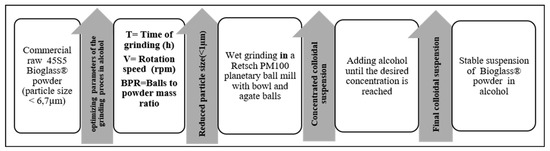
Figure 1.
Flowchart of the wet grinding process of the 45S5 Bioglass® powder.
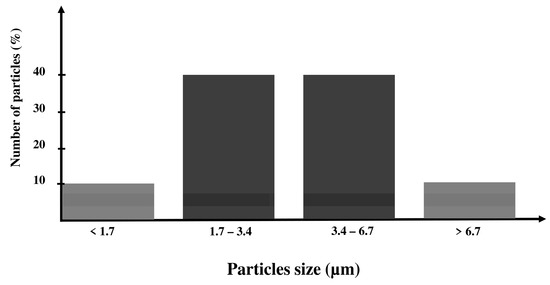
Figure 2.
Particle size distribution of the 45S5 Bioglass®.
2.2. Measurement of the Particle Size Distribution
The measurement of the 45S5 Bioglass® powder particle size distribution obtained after the wet grinding in ethanol or isopropanol (2-propanol, 99,5%, Alfa Aesar, Haverhill, MA, USA) was performed with a Nano Series-Malvern (10 mW, 632.8 nm, Red Laser, Ltd., Worcestershire, UK) instrument using dynamic light scattering (DLS). The DLS technique measures fluctuations in light intensity caused by Brownian motion and then relates this motion to the size of particles. This fluctuation is strong in the case of small particles due to a high diffusion coefficient and weak in the case of coarse particles. In a typical DLS experiment, the suspension is exposed to a monochromatic wave of light and an appropriate detector detects the signal. The measurement of the intensity of the light scattered provides information about the particle size. The DLS technique allows particle sizing under 1 µm. DLS is mainly employed for nanoparticles, emulsions and proteins. It allows the hydrodynamic behaviour to be determined by providing information about both particle size and aggregation. It offers the possibility to work with a wide range of temperatures and concentrations from a small amount of powder [18]. The calculation of the diffusion coefficient D is related to the radius R of the particles by the Stokes–Einstein equation [19]: D = kT/6πηR, where k is the Boltzmann’s constant, T the temperature, R the radius of a particle and η the viscosity of the solution (in this study, the viscosity values are: ηethanol = 1.07 × 10⁻³ Pa·s and ηisopropanol = 2.37 × 10⁻³ Pa·s.)
2.3. Electrophoretic Deposition
The EPD experiments were carried out using a 4 wt.% suspension of the 45S5 Bioglass® powder obtained after a wet optimal grinding in isopropanol. To break the powder agglomerates, the suspension was ultrasonically agitated during 20 min by using an ultrasonic bath (Elmasonic S, Fisher Scientific, Hampton, NH, USA) operating at 50 kHz. The particles are positively charged in contact with isopropanol, and therefore, cathodic deposition was performed. EPD is usually carried out in a two-electrode cell, as shown in Figure 3. The two electrodes are made of Ti-6Al-4V (Table 1, ASTM F136 [20], CRITT-MDTS) as discs (12 mm in diameter and 4 mm in thickness). Before deposition, the cathode disc surface was treated by projection of alumina particles to increase its roughness (about 2.8 µm) in order to improve the coating adhesion. This treatment is followed by dipping in pure acid for 10 s (to eliminate any alumina residue) and ultrasonic cleaning in acetone (Acetone technical, Acros Organics, Geel, Belgium), then in distilled water.
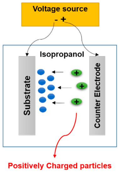
Figure 3.
Sketch of the electrophoretic deposition process.

Table 1.
Chemical composition of the Ti6Al4V alloy substrate.
The EPD process was carried out at ambient temperature using a controlled power supply PS 304 minipac II (APELEX). This power supply allows working under two modes: direct current (maximum intensity 400 mA) and direct voltage (maximum voltage 300 V). The two metallic electrodes were immerged vertically into the EPD cell at a distance of 8 mm, and the Ti-6Al-4V substrate was used as the cathode. Different direct voltages (10, 20, 30 and 50 V) and different times (30 s, 1 min, 1 min 30 s and 2 min) were tested in order to optimize the quality of the films. Finally, the as-deposited coatings were air dried at room temperature for 24 h before their thermal treatment in air.
2.4. Thermal Treatment in Air
As the deposition process is carried out inside a liquid medium, it requires a thermal treatment after the deposition to evaporate the solvent trapped within the 45S5 Bioglass® coating. Moreover, the thermal treatment helps to improve the adhesion strength of the 45S5 Bioglass® coatings to the Ti6Al4V substrate along with preserving the substrate from oxidation. It was performed in air inside a furnace (Thermolyne FB 1400, Thermo Scientific, Waltham, MA, USA) equipped with an Eurotherm 2116 Regulator, allowing a range of temperatures from ambient to 1100 °C. It also allows the control of the heating rate and the annealing time to program a plateau. The Figure 4 presents the protocol used which is inspired from our previous work [21]. The temperature is increased from room temperature (RT) with a heating rate of 5 °C/min to a first plateau at 120 °C during 1 h to completely evaporate the solvent entrapped into the coating. Then the temperature was increased, with the same heating rate of 5 °C/min, to a second plateau at 450 °C for 1 h to improve the coatings compactness and their bond strength to the substrate. The selected temperature for the thermal treatment was limited at 450 °C to avoid the titanium substrate oxidation and the 45S5 glass transition which occurs between 505 and 550 °C [22]. Indeed, the choice of the thermal temperature is an important parameter regarding the 45S5 bioactivity which is related to the hydroxyapatite surface layer formation [23].
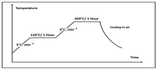
Figure 4.
Heat treatment protocol.
2.5. Scanning Electron Microscopy and Energy Dispersive X-ray Spectroscopy (SEM-EDXS)
The as-deposited and the heat-treated coatings were characterized in terms of surface morphology and chemical composition by means of a LaB6 scanning electron microscope (JEOL JSM-5400LV, JEOL, Tokyo, Japan), operating at 0–30kV. This microscope is associated with an energy dispersive X-ray spectrometer (EDXS) (Éloise, Tremblay en France, France) equipped with an ultra-thin window Si (Li) detector cooled with liquid nitrogen. All the X-ray spectra were obtained with energy of 15 keV and an acquisition time of 100 s.
2.6. X-ray Diffraction (XRD)
The phase composition of the coatings was studied by XRD with a DRON-3 diffractometer (Bourevestnik, Saint Petersbourg, Russia) using a monochromatic copper radiation (CuKα) of wavelength λ = 0.15406 nm. The X-ray diffraction patterns were recorded in a range of diffraction angles 2θ between 10° and 80° by steps of 0.04° with an acquisition time of 12 s per step. These experimental parameters were optimized to enhance the resolution for an accurate identification of the phases. The crystalline phases were identified from the powder diffraction files of the International Centre for Diffraction Data (ICDD).
2.7. Scratch Test
The scratch test was performed with a scratch-tester (CSM Instruments, Peuseux, Switzerland) which was equipped with Rockwell HRC penetrator with the tip of 120 cone angle and 200 μm radius. The loading speed was 10 mm·min−1, and the track length was 3 mm. The normal load of the indenter onto the coating surface increased continuously from 0 to 10 N (Figure 5) with a load rate of 32.33 N·min−1, corresponding to a total experimental time of 18 s.
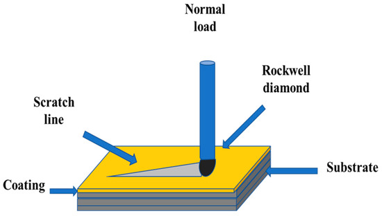
Figure 5.
Sketch of the scratch test.
A minimum of three scratches were made on each sample. The scratch tests were coupled with SEM observations to investigate the scratches tracks and to determine the critical loads. Different failure modes may be observed while increasing the normal load and help to deduce the mechanical behaviour of the deposited coatings. Three critical loads may be identified along with the scratch length which help to characterize the coating failure mechanisms [24,25]:
- LC1: the critical load corresponding to the appearance of the first cracks matching the cohesive failure of the coating.
- LC2: the critical load corresponding to the first delamination of the coating
- LC3: the critical load corresponding to the total removal of the coating. It generally corresponds to a percentage of film damage which exceeds 50%.
2.8. Coatings Thickness Measurement
This measurement was performed according to the method presented on Figure 6. First, the sample was embedded into a resin to obtain a block (Figure 6a). The block was cut at a moderate speed to avoid the tearing and the detachment of the coating from the substrate (Figure 6b). A cross-section of the sample was then obtained (Figure 6c), and the use of the scale bar allowed the mean thickness of the coating to be estimated.
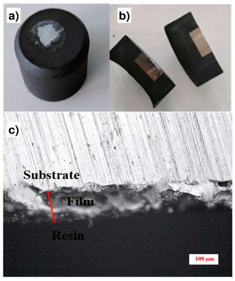
Figure 6.
Methodology for the coating thicknesses measurement: (a) The sample is embedded into a resin block; (b) Cross-section of the resin block; (c) Optical observation of the cross-section.
3. Results and Discussion
3.1. Optimization of the 45S5 Bioglass® Powder Grinding
Table 2 presents the different mill parameters (time (T), rotation speed (V) and powder to balls mass ratio (BPR)) tested separately in ethanol and isopropanol to optimize the 45S5 Bioglass® powder grinding. In each alcohol, four different tests were performed. The optimal suspension for EPD was obtained by the wet grinding WG 4 corresponding to a BPR of 30 and a grinding velocity of V = 600 rpm during T = 2 h. Indeed, the particle size distribution was reduced from less than 6.7 µm (commercial 45S5 Bioglass® powder) to about 1 to 3 µm in the case of ethanol (Figure 7a) and to about 350 to 850 nm in the case of isopropanol (Figure 7b). Thus, isopropanol allows a colloidal suspension of 45S5 Bioglass® particles to be obtained, and it was chosen to evaluate the suspension stability. Due to its dielectric constant, its higher molecular weight and its viscosity, isopropanol proved to be the best suspension medium for EPD. Figure 8 shows the time evolution of the 4 wt.% suspension obtained after the optimal grinding in isopropanol. One can clearly observe that the suspension presented an excellent stability up to 7 h. This suspension was then suitable for the coating deposition by EPD.
Table 2.
Wet grinding settings of 45S5 Bioglass®.
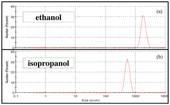
Figure 7.
Particle size distributions of the 45S5 Bioglass® powder after the optimal Wet grinding WG4 (see Table 2): (a) ethanol; (b) isopropanol.
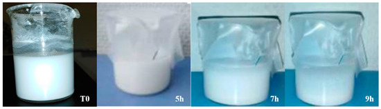
Figure 8.
Suspension stability study of the 4 wt% suspension prepared in isopropanol.
3.2. Optimization of the EPD Parameters
To produce 45S5 Bioglass® coatings with higher quality in terms of thickness and structural properties as well as adhesion to the metallic substrate, we studied the effect of two experimental deposition parameters: the voltage and the deposition time. Several parameters are responsible for the final quality of the deposited coating, its thickness and its adhesion strength to the metallic substrate. The voltage seems to be the most important one. According to Corni et al. [26], the voltage applied during the process is linked to the migration force that sets in motion the particles in the suspension towards the substrate, which finally accumulate to form the coating. The applied voltage is directly related to the accumulation speed of the particles and thus to the coating quality.
The effect of the voltage variation is shown in Figure 9, which presents optical micrographs of the 45S5 Bioglass® coatings obtained by EPD for 2 min at 10, 20, 30 and 50 V. The visual and optical observations of the samples obtained at low voltages (10 V, 20 V) reveal the presence of pores. When the EPD voltage is not enough to allow a sufficient particle motion in the suspension, the deposition of a homogeneous coating is not possible [27]. On the other hand, the coating deposited at 50 V appears to be very thick with the appearance of cracks. Finally, the coating deposited at 30 V is the most homogeneous one. This optimal voltage was selected to test the effect of the deposition time. Different deposition times were tested. The visual and optical observations revealed that the three coatings obtained after 30 s, 1 min and 1 min 30 s are highly homogeneous (Figure 10a), but after 2 min, cracks appeared at the coating surface (Figure 10b). In this case, too many particles agglomerated on the surface of the substrate which induced an inhomogeneous accumulation and a too high thickness, resulting in crack formation during the solvent evaporation [28]. Based on all these results, two deposition times were chosen (30 s and 1 min 30 s) in order to obtain two different coating thickness ranges. Indeed, the coating thickness is an important parameter for the mechanical and structural properties of the implant. The measurement of their thicknesses, according to the method presented in Section 2.8, is presented in Table 3. One can clearly observe that the choice of the two optimal EPD parameters (30 V, 30 s and 30 V, 90 s) resulted in a thin coating (21 µm) and a thick coating (85 µm), respectively, called C30 and C90.
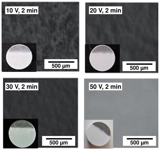
Figure 9.
Optical micrographs of the 45S5 Bioglass® coatings obtained by electrophoretic deposition (EPD) for 2 min at 10, 20, 30 and 50 V.
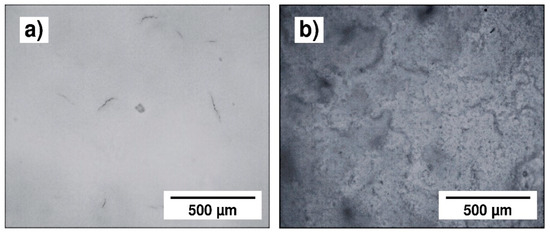
Figure 10.
Optical micrographs of the 45S5 Bioglass® coatings obtained by EPD at 30 V, (a) for 1 min and (b) for 2 min.
Table 3.
Thickness values of the two optimal 45S5 Bioglass® coatings.
3.3. Morphological, Chemical and Structural Analyses
Figure 11 presents the SEM micrographs of the two chosen samples, C90 and C30. The C30 surface morphology (micrograph a) clearly revealed a highly homogeneous coating without important cracks or holes, whereas a cracks network is clearly visible on the C90 surface (Figure 11c). This crack formation can be related to the strong increase in the coating thickness and to the evaporation of isopropanol trapped within the coating during air drying [29]. The two high magnification Figure 11b,d revealed that both coatings are highly dense and formed by agglomeration of submicrometric particles. The EDXS spectrum obtained with the C30 sample is presented in Figure 11e. All elements of the 45S5 Bioglass® are clearly identified on the spectrum, which proves that the powder composition is not modified during grinding and during EPD.
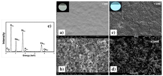
Figure 11.
SEM micrographs of the C30 (a,b) and of the C90 (c,d) as deposited coatings on the Ti6Al4V alloy at two different magnifications. (e) EDXS spectrum of the C30 coating.
Figure 12 presents the SEM micrographs of the C30 and C90 coatings after the heat treatment presented on Figure 3. One may observe on the low magnification Figure 12a,c that the thermal treatment results in the cracks increasing whatever the thickness. This can be explained by the evaporation of solvent trapped within the coating during EPD and by the difference between the thermal expansion coefficients of the substrate and the coating [30]. The two high magnification Figure 12b,d revealed that during heat treatment, the surface coating morphology is preserved, remaining rough and porous. The EDXS spectrum obtained with the C30 sample (inset of micrograph b) reveals all the elements of the 45S5 Bioglass®, which indicates that the coating composition was not modified during the thermal treatment.
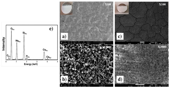
Figure 12.
SEM micrographs of the C30 (a,b) and of the C90 (c,d) coatings on the Ti6Al4V alloy after heat treatment at two different magnifications. (e) EDXS spectrum of the heat treated C30 coating.
These observations were completed by the XRD patterns of the C30 coating, obtained before and after thermal treatment, presented on Figure 13. Both diffraction patterns show the characteristic peaks of the Ti6Al4V substrate (pdf # 44-1994) due to the low thicknesses of the coating [21]. Before heat treatment (pattern (1)), the amorphous structure of the coating, due to the melting-quenching synthesis process of the 45S5 Bioglass® powder, is clearly identified. However, some peaks can be attributed to the following crystalline phases: Na2Ca3Si2O8 (pdf # 00-023-0670), Na2CaSiO4 (pdf # 00-023-0670) and Na1.8Ca1.1(Si6O14) (pdf # 01-086-0139). The presence of these weak diffraction peaks can be explained by the quenching speed of the 45S5 Bioglass® powder [31]. The X-ray diffraction pattern (2) obtained after heat treatment reveals sharper peaks attributed to the crystalline phases Na2Ca3Si2O8 (pdf # 00-023-0670) and Na2CaSiO4 (pdf # 00-023-0670). This XRD pattern also shows that both the weak crystallinity and the chemical composition of the coating are not modified by the thermal treatment.
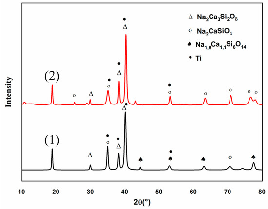
Figure 13.
X-ray diffraction (XRD) pattern of C30 coating before (1) and after thermal treatment (2).
3.4. Mechanical Study by SCRATCH Tests
The scratch tests realized on the as deposited C30 and C90 coatings are shown on Figure 14 and Figure 15. One may observe for both coatings that the friction force and the penetration depth increased when the normal load varied from 0 to 10 N. The slope changes indicate the first cohesive failure in the coating giving the critical load values (Lc) shown in Table 4. In the case of the C30 coating (Figure 14b), LC = 5.18 ± 0.22 N, while for the C90 coating, the critical load decreased to LC = 3.39 ± 0.15 N (Figure 15b). This result allows us to suggest that the cohesive failure of the coating is significantly reduced when the coating thickness is increased from 21 (C30) to 85 µm (C90). On the other hand, the slope of the C30 penetration depth curve is lower than that of the C90. Therefore, the C30 coating appears to be more compact than the C90 coating. These results are confirmed by the SEM images of Figure 14a and Figure 15a which clearly show that the scratch tracks of the C30 coating is less wide and closer to the surface than that of the C90 coating. The increase in the coating compactness with the thickness reduction was observed by Teghil et al. [32] in the case of bioactive glass films deposited on Ti6Al4V alloy by pulsed laser ablation.
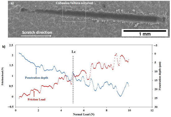
Figure 14.
Scratch test of the as deposited C30 coating: (a) SEM micrograph of the scratch and (b) friction load and penetration depth as a function of normal load.
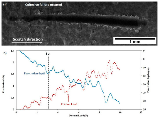
Figure 15.
Scratch test of the as deposited C90 coating: (a) SEM micrograph of the scratch and (b) friction force and penetration depth as a function of normal load.
Table 4.
Critical loads LC calculated from the friction–load curves for both coatings C30 and C90 before and after thermal treatment.
After thermal treatment, the Figure 16 and Figure 17 show that, for both coatings, the penetration depths reduced, and the critical loads significantly increase to LC = 5.92 ± 0.32 N (C30 coating) and to LC = 4.93 ± 0.26 N (C90 coating) as shown in Table 4. In addition, the thermal treatment improved the compactness of the coatings without altering their chemical composition.
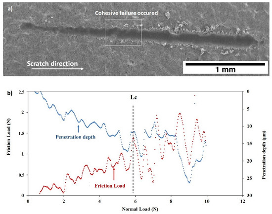
Figure 16.
Scratch test of the C30 coating after thermal treatment: (a) SEM micrograph of the scratch and (b) friction force and penetration depth as a function of normal load.
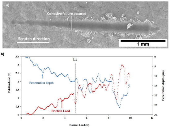
Figure 17.
Scratch test of the C90 coating after thermal treatment: (a) SEM micrograph of the scratch and (b) friction force and penetration depth as a function of normal load.
4. Conclusions
In this work, 45S5 Bioglass® coatings were obtained by electrophoretic deposition on the Ti6Al4V alloy. A stable suspension of 45S5 Bioglass® particles was obtained by a wet milling process developed in isopropanol. Then EPD was performed by using a voltage of 30 V and two deposition times (30 and 90 s) to obtain two coatings with a thickness of 21 and 85 µm, respectively. After EPD, the coatings were thermally treated following a two-step protocol—one hour at 120 °C followed by one hour at 450 °C. The surface characterizations showed that the chemical composition of the 45S5 Bioglass® was not altered by the thermal treatment. The coatings remain homogeneous and weakly crystallized. The scratch tests showed good compactness, hardness and bonding strength of the coatings depending on its thickness. The biocompatibility and the bioactivity of these coatings have to be performed to assess their clinical and industrial potentials. These works are in progress.
Author Contributions
Conceptualization, J.F., A.C.L., and H.B.; methodology, I.A., J.F., and K.K.; validation, I.A., J.F., K.K., A.C.L., and H.B.; investigation, I.A., J.F., K.K., A.C.L., and H.B.; resources, J.F. and H.B.; writing—original draft preparation, I.A. and J.F.; writing—review and editing, I.A., J.F., K.K., A.C.L., and H.B.; supervision, J.F., A.C.L., and H.B.; project administration, A.C.L. and H.B.; funding acquisition, A.C.L. and H.B. All authors have read and agreed to the published version of the manuscript.
Funding
This research was funded by the Tunisian Ministry of Research and by the PHC UTIQUE project N° 44054ZE.
Acknowledgments
The authors would like to thank Hassane Oudadesse and Bertrand Lefeuvre from Rennes University for their help concerning DLS experiments.
Conflicts of Interest
The authors declare no conflict of interest.
References
- Sivakumar, M.; Rajeswari, S.; Thulasiraman, V. Metallographic investigation of a failed stainless steel orthopaedic implant device. J. Mater. Sci. Lett. 1996, 15, 2192–2194. [Google Scholar] [CrossRef]
- Bruni, S.; Martinesi, M.; Stio, M.; Treves, C.; Bacci, T.; Borgioli, F. Effects of surface treatment of Ti-6A1-4V titanium alloy on biocompatibility in cultured human umbilical vein endothelial cells. Acta Biomater. 2005, 1, 223–234. [Google Scholar] [CrossRef] [PubMed]
- Inoue, X.A.; Nose, M.; Masumoto, T. Amorphous alloys with low boron concentration. J. Phys. Colloq. 1980, 41, 331–342. [Google Scholar] [CrossRef]
- Niinomi, M.; Liu, Y.; Nakai, M.; Liu, H.; Li, H. Biomedical titanium alloys with Young’s moduli close to that of cortical bone. Regen. Biomater. 2016, 3, 173–185. [Google Scholar] [CrossRef] [PubMed]
- Rho, J.Y.; Ashman, R.B.; Turner, C.H. Young’s modulus of trabecular and cortical bone material: Ultrasonic and microtensile measurements. J. Biomech. 1993, 26, 111–119. [Google Scholar] [CrossRef]
- Królczyk, G.M.; Niesłony, P.; Królczyk, J. Industrial Measurements in Machining; Springer International Publishing: Berlin, Germany, 2020. [Google Scholar]
- Bagno, A.; Di Bello, C. Surface treatments and roughness properties of Ti-based biomaterials. J. Mater. Sci. Mater. Med. 2004, 15, 935–949. [Google Scholar] [CrossRef]
- Ducheyne, P.; Qiu, Q. Bioactive ceramics: The effect of surface reactivity on bone formation and bone cell function. Biomaterials 1999, 20, 2287–2303. [Google Scholar] [CrossRef]
- Hench, L.L. Bioceramics. J. Am. Ceram. Soc. 1998, 81, 1705–1728. [Google Scholar] [CrossRef]
- Shirtliff, V.J.; Hench, L.L. Chemical and bio-ceramics bioactive materials for tissue engineering, regeneration and repair. J. Mater. Sci. 2003, 38, 4697–4707. [Google Scholar] [CrossRef]
- Fiume, E.; Barberi, J.; Verné, E.; Baino, F. Bioactive glasses: From parent 45S5 composition to scaffold-assisted tissue-healing therapies. J. Funct. Biomater. 2018, 9, 24. [Google Scholar] [CrossRef]
- Jones, J.R.; Gentleman, E.; Polak, J. Bioactive glass scaffolds for bone regeneration. Elements 2007, 3, 393–399. [Google Scholar] [CrossRef]
- Xynos, I.D.; Edgar, A.J.; Buttery, L.D.K.; Hench, L.L.; Polak, J.M. Gene-expression profiling of human osteoblasts following treatment with the ionic products of bioglass 45S5 dissolution. J. Biomed. Mater. Res. 2001, 55, 151–157. [Google Scholar] [CrossRef]
- Fathi, M.H.; Doostmohammadi, A. Bioactive glass nanopowder and bioglass coating for biocompatibility improvement of metallic implant. J. Mater. Process. Technol. 2009, 209, 1385–1391. [Google Scholar] [CrossRef]
- Cattini, A.; Bellucci, D.; Sola, A.; Pawłowski, L.; Cannillo, V. Microstructural design of functionally graded coatings composed of suspension plasma sprayed hydroxyapatite and bioactive glass. J. Biomed. Mater. Res. Part B Appl. Biomater. 2014, 102, 551–560. [Google Scholar] [CrossRef]
- Kuo, P.H.; Joshi, S.S.; Lu, X.; Ho, Y.H.; Xiang, Y.; Dahotre, N.B.; Du, J. Laser coating of bioactive glasses on bioimplant titanium alloys. Int. J. Appl. Glas. Sci. 2019, 10, 307–320. [Google Scholar] [CrossRef]
- Boccaccini, A.R.; Keim, S.; Ma, R.; Li, Y.; Zhitomirsky, I. Electrophoretic deposition of biomaterials. J. R. Soc. Interface 2010, 7, S581–S613. [Google Scholar] [CrossRef]
- Stetefeld, J.; McKenna, S.A.; Patel, T.R. Dynamic light scattering: A practical guide and applications in biomedical sciences. Biophys. Rev. 2016, 8, 409–427. [Google Scholar] [CrossRef]
- Shire, S.J. The molecular basis of high viscosity of monoclonal antibodies (mAbs) at high concentration. Monoclon. Antibodies 2015, 163–192. [Google Scholar] [CrossRef]
- Standard Specification for Wrought Titanium-6Aluminium-4Vanadium ELI (Extra Low Interstitial) Alloy for Surgical Implant Applications (UNS R56401); ASTM International: West Conshohocken, PA, USA, 2013.
- Ben Jaber, N.; Drevet, R.; Fauré, J.; Demangel, C.; Potiron, S.; Tara, A.; Ben Cheikh Larbi, A.; Benhayoune, H. A New process for the thermal treatment of calcium phosphate coatings electrodeposited on Ti6Al4V substrate. Adv. Eng. Mater. 2015, 17, 1608–1615. [Google Scholar] [CrossRef]
- Bretcanu, O.; Chatzistavrou, X.; Paraskevopoulos, K.; Conradt, R.; Thompson, I.; Boccaccini, A.R. Sintering and crystallisation of 45S5 Bioglass® powder. J. Eur. Ceram. Soc. 2009, 29, 3299–3306. [Google Scholar] [CrossRef]
- Filho, O.P.; Latorre, G.P.; Hench, L.L. Effect of crystallization on apatite-layer formation of bioactive glass 45S5. J. Biomed. Mater. Res. 1996, 30, 509–514. [Google Scholar] [CrossRef]
- ISO-ISO 20502:2005-Fine Ceramics (Advanced Ceramics, Advanced Technical Ceramics)—Determination of Adhesion of Ceramic Coatings by Scratch Testing. Available online: https://www.iso.org/standard/34189.html (accessed on 26 June 2020).
- Khlifi, K.; Ben Cheikh Larbi, A. Investigation of adhesion of PVD coatings using various approaches. Surf. Eng. 2013, 29, 555–560. [Google Scholar] [CrossRef]
- Corni, I.; Ryan, M.P.; Boccaccini, A.R. Electrophoretic deposition: From traditional ceramics to nanotechnology. J. Eur. Ceram. Soc. 2008, 28, 1353–1367. [Google Scholar] [CrossRef]
- Drevet, R.; Ben Jaber, N.; Fauré, J.; Tara, A.; Ben Cheikh Larbi, A.; Benhayoune, H. Electrophoretic deposition (EPD) of nano-hydroxyapatite coatings with improved mechanical properties on prosthetic Ti6Al4V substrates. Surf. Coat. Technol. 2016, 301, 94–99. [Google Scholar] [CrossRef]
- Drevet, R.; Fauré, J.; Benhayoune, H. Thermal treatment optimization of electrodeposited hydroxyapatite coatings on Ti6Al4V substrate. Adv. Eng. Mater. 2012, 14, 377–382. [Google Scholar] [CrossRef]
- Farrokhi-Rad, M.; Shahrabi, T. Effect of suspension medium on the electrophoretic deposition of hydroxyapatite nanoparticles and properties of obtained coatings. Ceram. Int. 2014, 40, 3031–3039. [Google Scholar] [CrossRef]
- Wang, X.; Xiao, P. Residual stresses and constrained sintering of YSZ/Al2O3 composite coatings. Acta Mater. 2004, 52, 2591–2603. [Google Scholar] [CrossRef]
- Lefebvre, L.; Chevalier, J.; Gremillard, L.; Zenati, R.; Thollet, G. Structural transformations of bioactive glass 45S5 with thermal treatments. Acta Mater. 2007, 55, 3305–3313. [Google Scholar] [CrossRef]
- Teghil, R.; D’alessio, L.; Ferro, D.; Barinov, S.M. Hardness of bioactive glass film deposited on titanium alloy by pulsed laser ablation. J. Mater. Sci. Lett. 2002, 21, 379–382. [Google Scholar] [CrossRef]


Publisher’s Note: MDPI stays neutral with regard to jurisdictional claims in published maps and institutional affiliations. |
© 2020 by the authors. Licensee MDPI, Basel, Switzerland. This article is an open access article distributed under the terms and conditions of the Creative Commons Attribution (CC BY) license (http://creativecommons.org/licenses/by/4.0/).