Article

Microstructure, Mechanical and Antibacterial Properties of TiNb-Based Alloy Implanted by Silver Ions

College of Materials Science and Technology, Nanjing University of Aeronautics and Astronautics, Nanjing 211106, China
*
Author to whom correspondence should be addressed.
Coatings 2021, 11(10), 1213; https://doi.org/10.3390/coatings11101213
Submission received: 3 September 2021 / Revised: 22 September 2021 / Accepted: 29 September 2021 / Published: 2 October 2021
(This article belongs to the Section Surface Characterization, Deposition and Modification)

Abstract

:
In this study, in order to obtain an antibacterial property for the TiNb-based alloy, the metal vapor vacuum arc (MEVVA) ion implantation technology was applied to implant the silver on the surface of TiNb-based alloy, which brought the change of the microstructures and mechanical properties for the surface of substrate. It was found that the diffusely distributed silver nanoparticles generated on the outermost surface of the implanted layer and the Ag element exist as a solid-solution state in the implanted layer. Meanwhile, the region of the implanted layer mainly constituted nanocrystalline structures based on the analyses of microstructures. Hence, the nanocrystalline strengthening effect formed by high-energy ion bombardment and the solid solution strengthening effect of silver atoms made contributions to the increase of surface comprehensive mechanical properties, including the surface hardness and elastic modulus. Finally, the suitable Ag-implanted specimen can obtain excellent antibacterial ability. Except for the antibacterial mechanism of silver ions release, the dispersed silver nanoparticles on the surface also provide the contact antimicrobial mechanism, which is the Schottky barrier–dependent antimicrobial efficacy of silver nanoparticles.

1. Introduction

Titanium and its alloys, by virtue of the high strength, low density, non-toxicity, and good biocompatibility, have become the preferred materials for human implants, such as artificial joint and bone [1,2,3,4]. Thereinto, the novel β-type titanium alloys, consisting of non-toxic elements and exhibiting low Young’s modulus close to bones, such as TiNb-based alloy, have been attracting increasing attention for application in biomedical implant materials [5,6]. However, the surface of the TiNb-based alloy does not have the antibacterial function, causing bacterial adhesion so as to form bacterial biofilm, which induces bacterial infection and the related serious complications of infection associated with the implants [7,8,9]. Much attention is needed to solve this issue, or else this issue would influence the service time of implants, and even lead to failure.
Nano-silver has a broad application prospect as a new antibacterial agent and has been shown to kill both Gram-positive and Gram-negative bacteria [10,11,12,13,14]. The interaction between silver nanoparticles and bacterial cells may release silver ions and produce reactive oxygen species (ROS), which interact with normal function membrane proteins, accumulating in the cell membrane and affecting the membrane permeability. Then, the silver nanoparticles enter the cells, where they can produce reactive oxygen species, release silver ions, and affect deoxyribonucleic acid (DNA) [15,16,17,18]. A common strategy for introducing antimicrobial properties into orthopedic material without significantly changing or overlaying the implant surface is through silver implantation [19,20,21]. Wang et al. found that the modified pure-Ti and Ti-6Al-7Nb by ion implantation of silver showed excellent antibacterial activity and enhanced wear resistance [22]. Cao et al. introduced silver nanoparticles and calcium ions into the titanium surface simultaneously through plasma immersion ion implantation technology to generate a current that promoted the consumption of cathode protons and the release of anode calcium ions, which synergically inhibited bacterial adhesion by increasing intracellular reactive oxygen species [23].
In this work, for the TiNb-based alloy to obtain an antibacterial property, the metal vapor vacuum arc (MEVVA) ion implantation technology was applied to implant the silver on the surface of TiNb-based alloy. The implanted ions from this technology, with extremely high kinetic energy, can cause the microstructure of substrate surface to change during the implantation course, and thereby can influence the surface mechanical properties. Kumar et al. reported that the nano-indentation hardness was found to increase to 10.26 GPa with the highest N+ ion dose due to the formation of surface nitrides and amorphous carbon [24]. Wang et al. found that the enhanced strengthening property of the silver implanted polycrystalline alpha-iron was mainly due to the formation of defects, super solid solution, and intermetallic compounds during the ion implantation [25]. Hence, this paper not only focused on the antibacterial property and antibacterial mechanism of Ag-implanted specimens, but also investigated the relationship between the microstructure and mechanical properties. Morphologies and microstructures of the Ag-implanted layer were analyzed by scanning electron microscope (SEM), grazing incidence X-ray diffraction (GIXRD), X-ray photoelectron spectroscopy (XPS), and transmission electron microscopy (TEM). The nano-indentation technology was employed to characterize the mechanical performance of the Ag-implanted layer. The antibacterial properties of Ag-implanted specimens were evaluated in an effective manner.

2. Materials and Methods

2.1. Modification of Specimens

A high energy metal ion implanter with a MEVVA ion source (LZX-700, Beijing Technol Science Co., Ltd., Beijing, China) was used to implant different doses of silver ions into the surface of substrate (Ti-45Nb alloy plates, 10 mm× 10 mm× 2 mm). The implantation chamber was vacuumed to a pressure of below 6.0 × 10⁻⁴ Pa. The cathode rod was composed of pure Ag metal with a purity of 99.99% weight. The accelerated voltage was 45 keV. The temperature of sample surface layer was below 200 ℃ during implanted process. The different implantation influences were 1 × 10¹⁶, 5 × 10¹⁶, 10 × 1016, and 15 × 1016 ions/cm2, from less to more.

2.2. Surface Characterization

Morphologies for the surface of Ag-implanted specimens were characterized via scanning electron microscopy (SEM; S-4800, Hitachi Co., Ltd., Tokyo, Japan) incorporating an energy dispersive spectrometer (EDS). The crystal structure of Ag-implanted layer was determined by X-ray diffraction (XRD; D8 Discover, Bruker Co., Ltd., Karlsruhe, Germany) equipped with Cu Ka radiation (wavelength: 0.15406 nm). The grazing incidence angle is 0.1° and the diffraction angle measurement ranged from 5° to 90° at a scanning speed of 2°/min. The chemical compositions and chemical states of Ag-implanted layer were explored by X-ray photoelectron spectroscopy (XPS; K-Alpha XPS system, Thermo Scientific Ltd., Waltham, MA, USA). The surface etching was performed by an argon ion gun (Thermo Scientific Ltd., Waltham, MA, USA), the etching area was 1000 μm2, and the etching velocity was 0.35 nm/s (based on the etching velocity of Ta2O5 under the same experimental conditions). TEM samples in the longitudinal section (depth direction) of the implanted layer were prepared by double-beam focused ion beam (FIB) technique, and the microstructure was characterized by high resolution transmission electron microscopy (HRTEM, Thermo Scientific Ltd., Waltham, MA, USA).

2.3. Mechanical Properties Tests

The surface mechanical properties of Ag-implanted specimens were tested and analyzed by the nano-indentation tester (NHT3, Anton Paar, Graz, Austria). This experiment adopted the static load control mode. The loading load was set as 5 mN, the loading speed was 0.33 mN/s, and the pressure holding time was 15 s. In order to ensure the accuracy of results, five times parallel experiments were performed. The surface hardness and elastic modulus of each specimen were calculated using the Oliver and Pharr method from the nano-pressed (displacements-loads) curves.

2.4. In Vitro Antibacterial Evaluation

Gram-positive Staphylococcus aureus (S. aureus, ATCC 29213) and Gram-negative bacteria Escherichia coli (E. coli, ATCC 25922) were used as experimental strains, and the bactericidal properties of different samples were measured by the plate counting method. The details of the experiment were as follows: (1) S. aureus or E. coli were diluted and separated to single bacterium by phosphate buffer solution (PBS). (2) A 60 μL prepared suspension of bacterial (107 cfu/mL) was dropped on the surface of each sample, ensuring that the bacterial liquid did not slide off the surface. (3) The tested samples were put into a constant temperature incubator at 37 °C for 24 h to incubate. (4) Specimens with the bacterial suspension were immersed into aseptic centrifuge tubes with 4 mL physiological saline, and then the tubes were vibrated drastically by the ultrasonic cleaner (Shanghai Jing Qi Co., Ltd., Shanghai, China) and vortex oscillator (Shanghai Jing Qi Co., Ltd., Shanghai, China) to make bacteria separate from the surface of samples. (5) These generating suspensions were attenuated 10, 100, and 1000 times by physiological saline in sequence. (6) The diluted bacteria suspension of 100 μL was dropped on each agar culture plate and the colonies were counted after culturing for 24 h. (7) The antibacterial rate (Ra) was calculated according to the Chinese National Standard GB/T4789.2 protocol; the formula is as follows:
Ra = (A − B)/A × 100%,
where A represents the number of bacteria colonies grown in the culture medium corresponding to the substrate specimen and B represents that of bacteria colonies about different composite coating specimens. Three numbers of the substrates and Ag-containing specimens were respectively selected and then the corresponding photos of the re-cultivated S. aureus and E. coli colonies on agar for different samples were observed and the antibacterial ratios were calculated.

3. Results

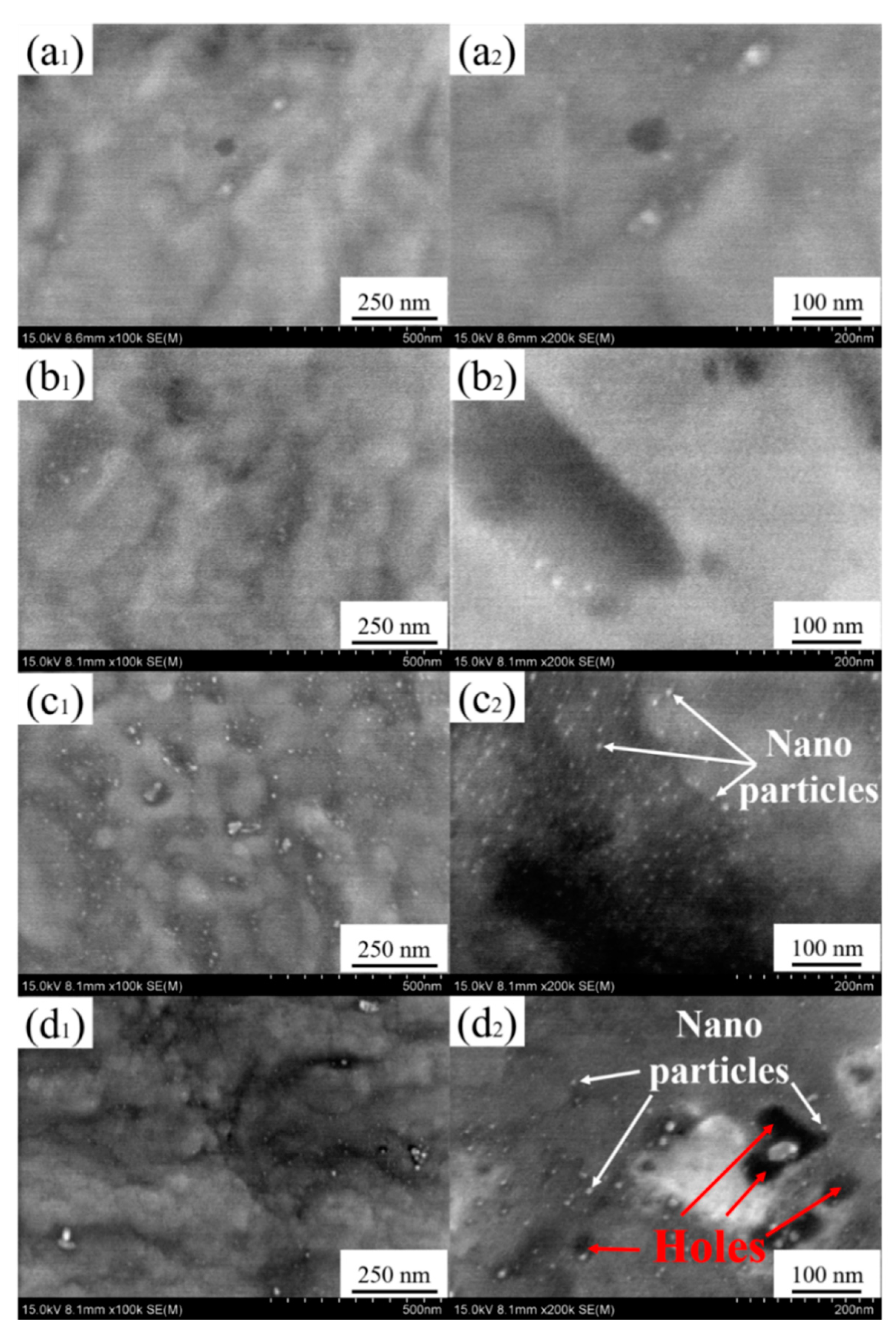
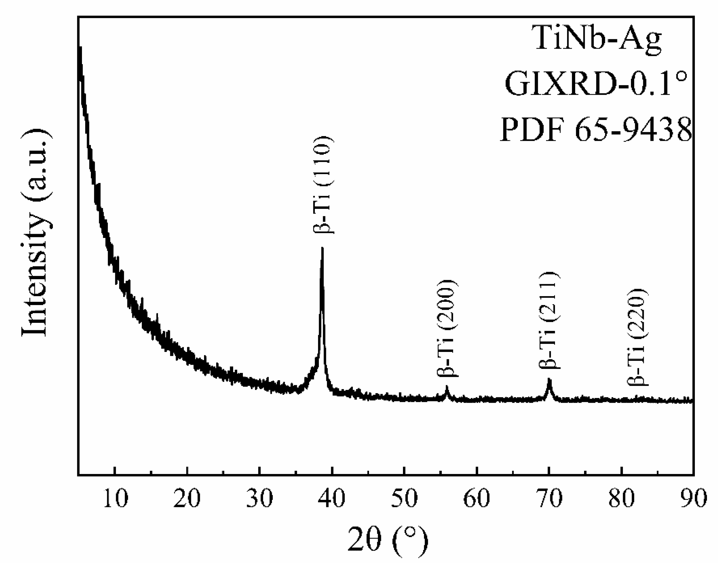
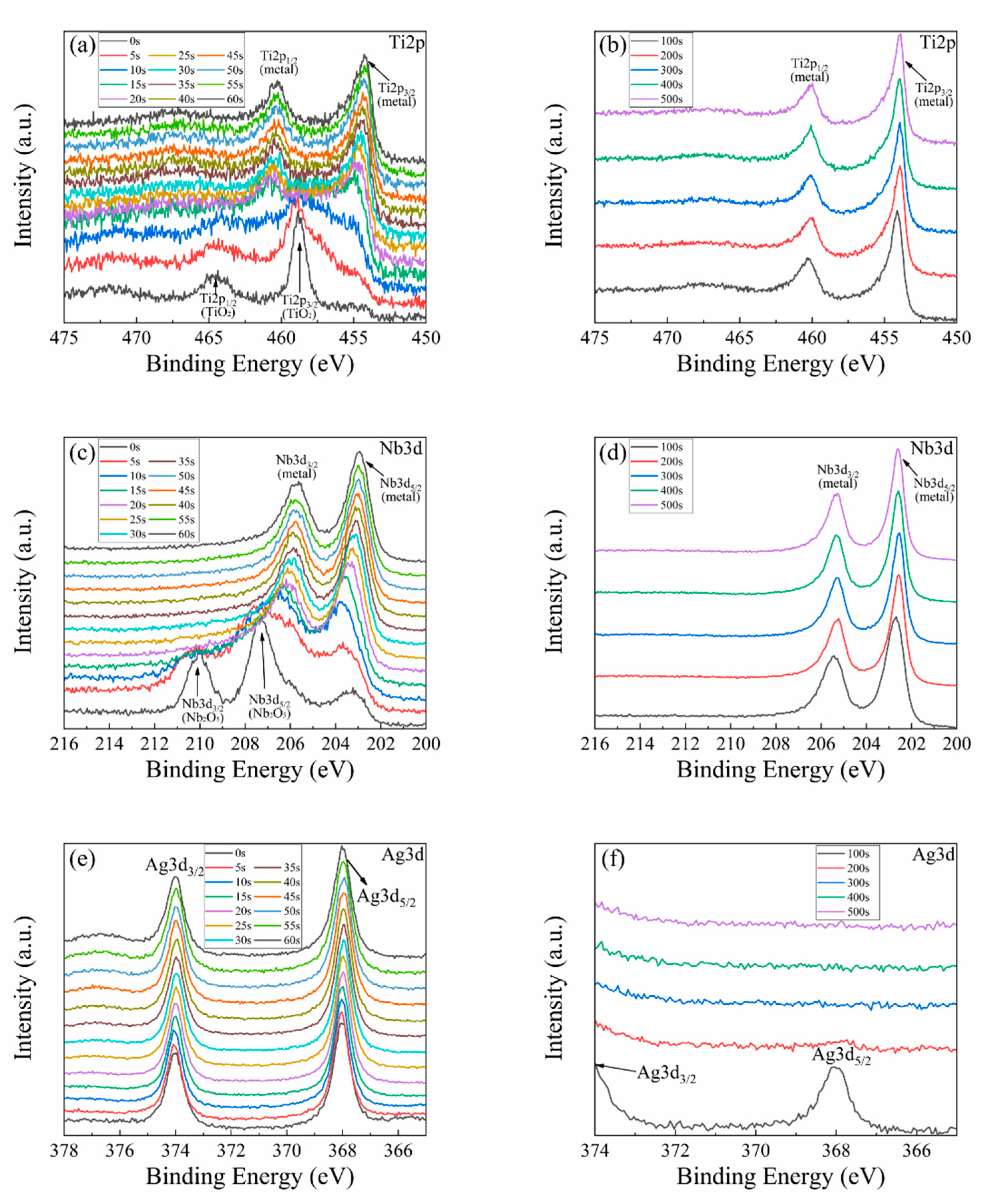
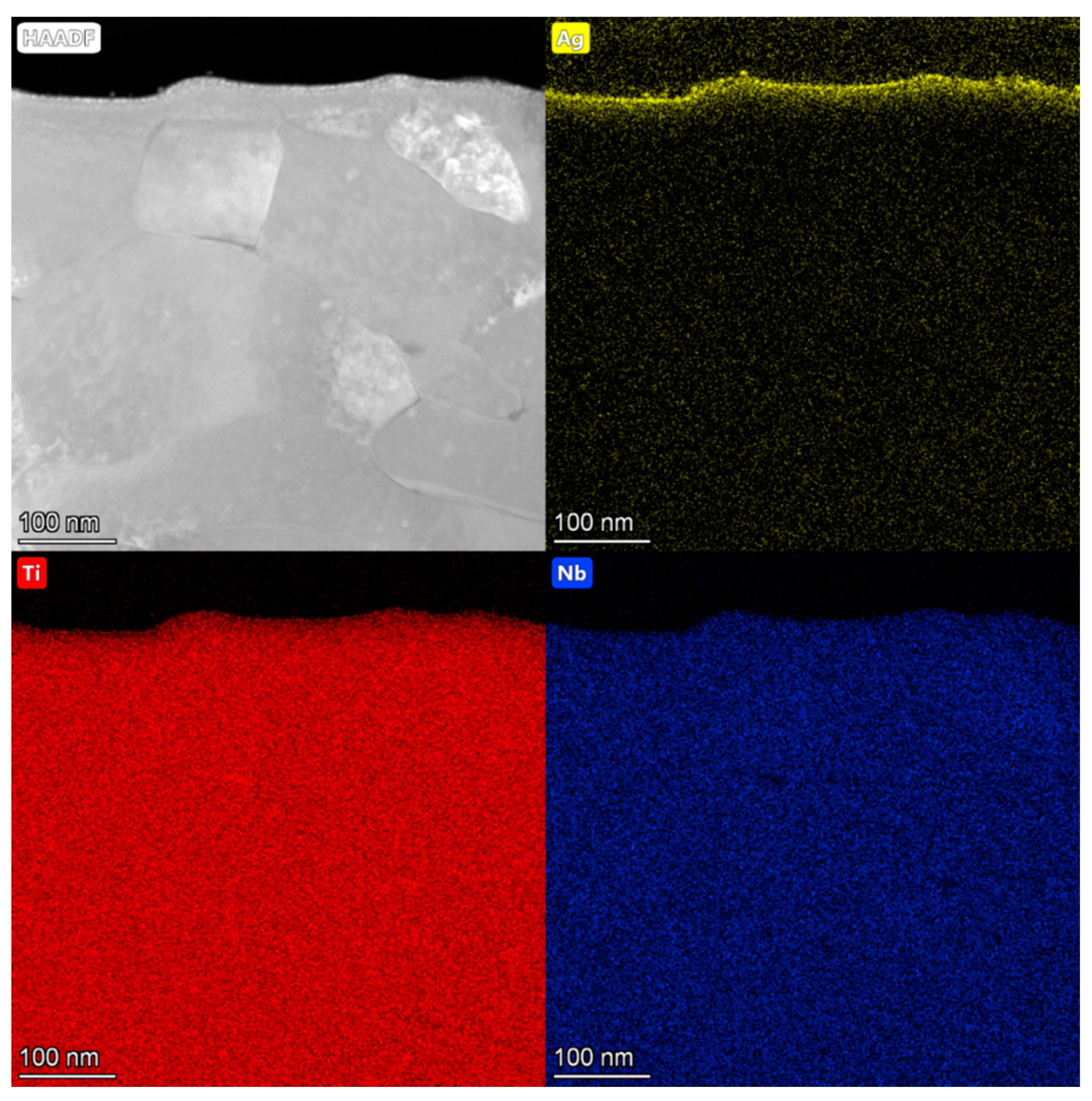
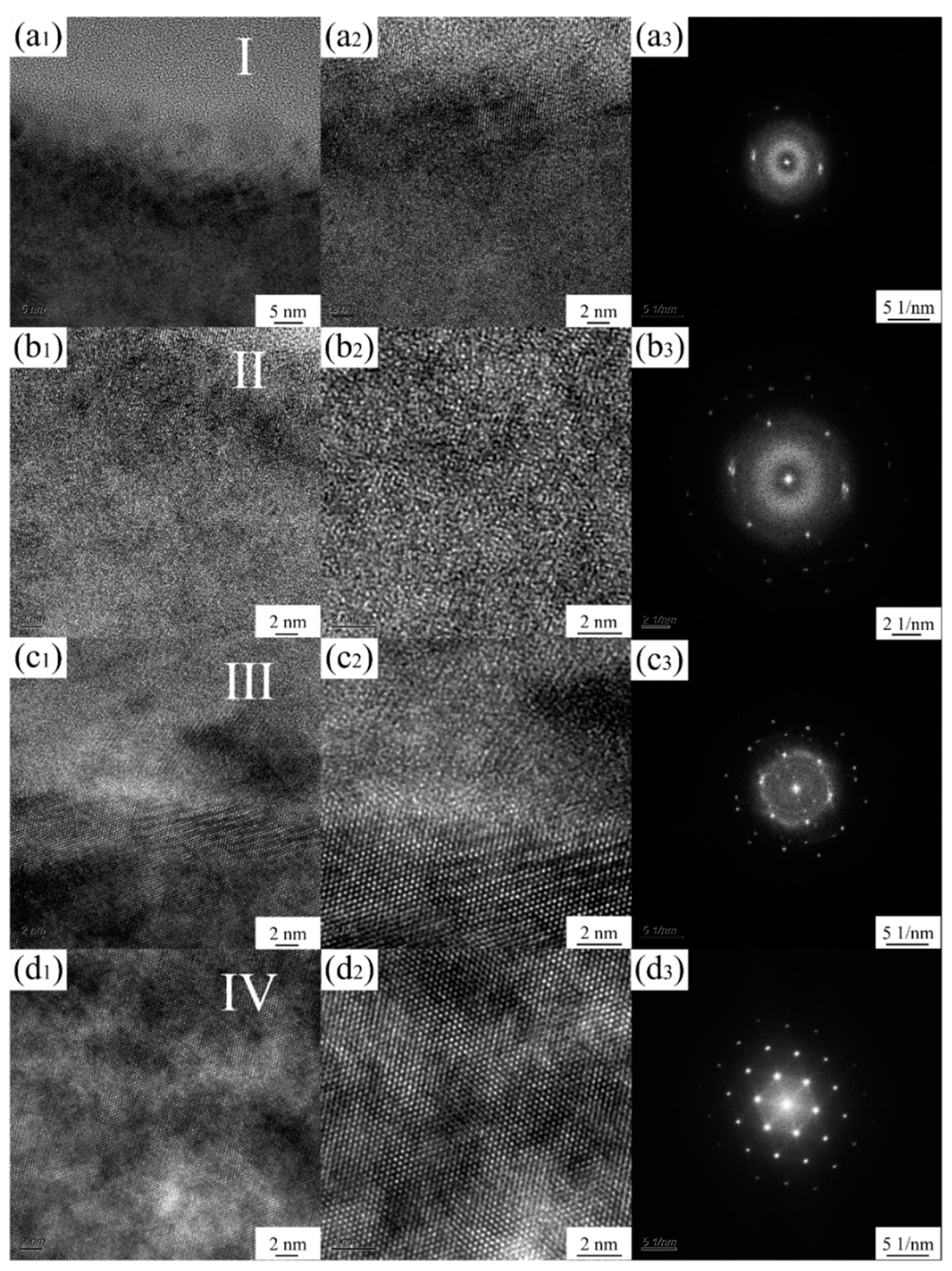
3.1. Characterization of Ag-Implanted Layer

Figure 1a–d show the SEM morphology image of Ti-45Nb alloy matrix and the elemental composition scanning analysis. It can be seen that the substrate is flat and smooth without defects. The contained Ti and Nb elements are evenly distributed without segregation, and the elemental atomic ratio is approximately 55:45, which is consistent with the nominal composition of the alloy. Figure 1e shows the XRD pattern of Ti-45Nb alloy matrix. The diffraction peaks appear at 38.721°, 55.916°, 70.086°, and 83.061°, corresponding to PDF 65-9438, indicating that the substrate is β-Ti phase. Figure 1f,g show the TEM bright field phase image and the selected area diffraction pattern of Ti-45Nb alloy matrix, exhibiting typical β-Ti phase structure characteristics and body-centered cubic (bcc, Im3m) structure, which also confirms that the Ti-45Nb alloy matrix is the β-Ti phase structure.
Figure 2 shows the surface morphologies of Ti-45Nb alloy implanted by different doses of silver ions. It is found that when the implantation dose stays in the low-level stage, the surface suffered from less damage, without obvious holes and cracks. However, when the implantation dose was at a higher level (up to 15 × 1016 ions/cm2), certain deformation damage occurred on the surface, with a few holes that appeared. Along with the silver ions implantation dose increase to 10 × 10 16 ions/cm2, a large number of nanoparticles were precipitated dispersively on the surface of specimen, as shown in Figure 2c2,d2. The surface element composition of TiNb alloy implanted with different doses of silver ions was performed by the EDS, and the results are shown in Figure 3. It is obvious that the Ag element is uniformly distributed on the surface after ion implantation, and the compositional segregation or aggregation does not exist. With an increase in the silver ions implantation dose, the Ag content on surface increases accordingly, but it is still maintained at a lower level, no more than 6% (weight percentage, wt.%), that is, 4% (atomic percentage, at.%).
In order to explore the phase structure of TiNb alloy surface after silver ions implantation, it was analyzed by the grazing incident XRD technique (incident Angle was 0.1°). Taking the Ag-implanted specimen with dose of 10 × 1016 ions/cm2 as the representative, the X-ray diffraction pattern is shown in Figure 4. The diffraction peak of β-Ti phase appears in 38.721°, 55.916°, 70.086°, and 83.061°, corresponding to the PDF card 65-9438, which can confirm that the surface phase composition after silver ions implantation was still the β-Ti, without a new phase generated. Remarkably, despite the grazing incident, XRD technique was employed, and it still had a diffraction depth of about dozens of nanometers. Thus, it can be deduced that the Ag element existed in the implanted layer by the way of solid solution into β-Ti, whereas the phase composition of nanoparticles on the outermost surface still has not been determined.
Figure 5 shows the XPS depth distribution map of each element in the Ag-implanted (10 × 1016 ions/cm2) layer. According to the analyses of Figure 5a,c, in the topmost layer, the binding energy of Ti2p3/2 peak is around at 458.5 eV and that of Nd3d5/2 peak is around at 207.1 eV. Refer to the standard XPS spectra of Ti and Nb elements, the chemical states were typical TiO2 oxidation phase and Nb2O5 oxidation phase. According to the etching time to judge, the depth range of the oxidation phases (TiO2 and Nb2O5) is about 3–5 nm. The existence of these oxidation phases may be related to the surface oxidation of TiNb alloy in the air [26]. Further analyses from Figure 5a–d indicate that the binding energy of Ti2p3/2 peak is around at 454.1 eV and that of Nd3d5/2 peak is around at 202.4 eV with the increase of depth (more than 5 nm) in the Ag-implanted layer, presenting as the metallic state. As shown in Figure 5e,f, it is observed that the Ag element exists in the implanted layer with a certain depth. As the etching time was less than 100 s, the typical diffraction peaks of Ag element (splitting for 3d3/2 and 3d5/2 peaks) obviously appeared in the XPS pattern. Meanwhile, when the etching time was more than 200 s, it was impossible to detect the peak of Ag element in XPS pattern. This suggests that the implantation depth range of silver ions is about 35~70 nm, that is, the thickness of the implanted layer is within this range. Significantly, whether at the top of implanted layer or within a certain depth (<70 nm), the binding energy of the Ag3d5/2 peaks are all around at 368 eV. Based on the standard XPS pattern of Ag element, the Ag element in the implanted layer mainly exists as the metallic state. Combined with the analyses from Figure 2c2 and Figure 4, it can be inferred that the diffusely distributed nanoparticles on the outermost surface are mainly as free state, namely, the silver nanoparticles. Moreover, the Ag element exists as solid-solution state in the implanted layer, appearing as a zero-valence metal state.
Figure 6 shows the TEM image of the cross section for Ag-implanted layer and the mapping images of the contained elements. It can be seen that the implanted Ag element is uniformly distributed and the depth of the implanted layer is about 40 nm, which is consistent with XPS analysis results. Figure 7 shows the TEM bright field images of this region and the diffraction pattern of corresponding selection. According to the analysis of diffraction pattern, still only the β-phase exists in the implanted layer without any new phase generated, which is consistent with the analysis results of X-ray diffraction pattern (Figure 4). However, compared with the diffraction pattern of substrate (Figure 1g), the nano-crystallization features appeared in this region. Further, in order to characterize and analyze the microstructure of this region (the implanted layer) more clearly, it was divided into four regions (region I, II, III and IV), as shown in Figure 7f.
Figure 8 shows the high-resolution TEM bright field images and the corresponding Fourier transform images of these four different regions. Region I is the most superficial region, and a large number of disordered structures can be observed from the atomic plane in the HR-TEM images, yet still a few ordered structures are included. By analyzing the corresponding Fourier transform in Figure 8a3, the obvious feature of amorphous halo rings are observed, which proves that the amorphous structure is formed in this region, accompanied with a certain nanocrystalline structure. Region II is the middle region of the implanted layer, and a large number of nanocrystalline structures appear with the crystal size of 2–5 nm. Referring to the corresponding Fourier transform, the non-crystalline characteristics of this region are weakened, while the crystalline characteristics begin to appear, testifying that this region is mainly constituted of nanocrystalline structures. Region III is the critical region for the implanted layer, in which the dividing line for different crystal structures is observed precisely. This indicates that the atoms of the implanted layer are nanocrystalline structures, while the non-ion implantation affected region maintains the original crystal structure (long-range order). The corresponding Fourier transform in Figure 8c3 also proves that the degree for crystal ordering in this region has increased further. Region IV is the non-ion implantation affected region. From Figure 8d2,d3 the crystal atomic plane arranges in order and the typical crystal structure of β phase in accordance with the substrate emerges in this region.

3.2. Mechanical Properties

In order to evaluate the surface mechanical properties of the implanted layer (in nanoscale), the nano-mechanical properties hardness (H) and elastic modulus (E) were measured by the nano-indentation method. Meanwhile, the H/E ratio means the resistance against elastic strain to failure, and the H3/E2 ratio is proportional to the resistance for plastic deformation. Figure 9a shows the curve of the displacement and load for the substrate and different doses of Ag-implanted specimens. Generally, under the same loading condition, the smaller the maximum pressed depth, the higher the hardness value of the sample. As shown in Figure 9a, when the loading force attained the maximum of 5 mN, the maximum pressed depth of substrate was 265 nm, and that of Ag-implanted specimens at 1 × 10¹⁶, 5 × 10¹⁶, 10 × 1016, and 15 × 1016 ions/cm2 were 263, 242, 203, and 275 nm, respectively. This suggests that with the increase of implantation dose, the pressed depth decreased, representing the increase of hardness. However, when the implantation dose exceeded a certain extent, the pressed depth increased and the hardness decreased significantly. Meanwhile, under the same loading conditions, the residual indentation depth after unloading can reflect the plastic deformation resistance of the sample. The smaller the maximum residual depth after unloading, the higher the plastic deformation resistance. Once the uninstall completed, the maximum residual depth of substrate after unloading was 223 nm, and that of Ag-implanted specimens at 1 × 10¹⁶, 5 × 10¹⁶, and 10 × 1016 ions/cm2 were 222, 202, and 157 nm, respectively. It can be seen that with the increase of implantation dose, the plastic deformation resistance of the specimen enhanced. However, when the implantation dose arrived at 15 × 1016 ions/cm2, the maximum residual depth (237 nm) increased rather than decreased, indicating that the plastic deformation resistance decreased conversely.
The Oliver–Pharr theory and calculation method were used to obtain the corresponding surface hardness and elastic modulus by analyzing the nanoindentation curves of different specimens, and the results are shown in Figure 9b. The surface hardness and elastic modulus of substrate are 3.216 and 101.8 GPa, respectively. With the increase of the implantation dose, the surface hardness and elastic modulus of specimens improve, and when the dose of silver ions reaches 10 × 1016 ions/cm2, the surface hardness and elastic modulus obtain the highest values (5.844 and 120.8 GPa, respectively), illustrating that the surface comprehensive mechanical properties of the specimen improve significantly at this dose. Compared with the microstructure analyses of the Ag-implanted layer in Figure 7 and Figure 8, the increase of surface hardness and elastic modulus after silver ions implanted is mainly attributed to the nanocrystalline strengthening effect formed by high-energy ion bombardment and the solid solution strengthening effect of silver atoms. When the implantation dose exceeds a certain extent, such as 15 × 1016 ions/cm2, the surface hardness and elastic modulus of this specimen decrease obviously. According to the surface SEM morphologies of this specimen in Figure 2d, severe radiation deformation damage occurred and a few holes appeared on the surface, which greatly weakened the strengthening effect of ion implantation, or even appeared the “softening effect” [27], causing the surface hardness and elastic modulus of the specimen to decrease significantly.
Meanwhile, H/E and H3/E2 were used to evaluate the surface comprehensive mechanical properties of the specimen. The H/E could better reflect the elastic strain failure resistance and the H3/E2 could better reflect the plastic deformation failure resistance. The H/E and H3/E2 for substate and different doses of Ag-implanted specimens are shown in Figure 9c. The H/E of substate and different Ag-implanted specimens are 31.58 × 10⁻³, 32.44 × 10⁻³, 36.14 × 10⁻³, 48.37 × 10⁻³, and 28.95 × 10⁻³, respectively. The H3/E2 are 3.21 × 10⁻³, 3.38 × 10⁻³, 5.05 × 10⁻³, 13.67 × 10⁻³, and 2.42 × 10⁻³ GPa, respectively. Both the values of H/E and H3/E2 increase along with the implantation dose increasing; however, as the implantation dose exceeds the critical value, the H/E and H3/E2 decrease conversely. In conclusion, the suitable implantation dose (10 × 1016 ions/cm2) of silver ions can remarkably improve the elastic strain failure resistance and plastic deformation failure resistance.

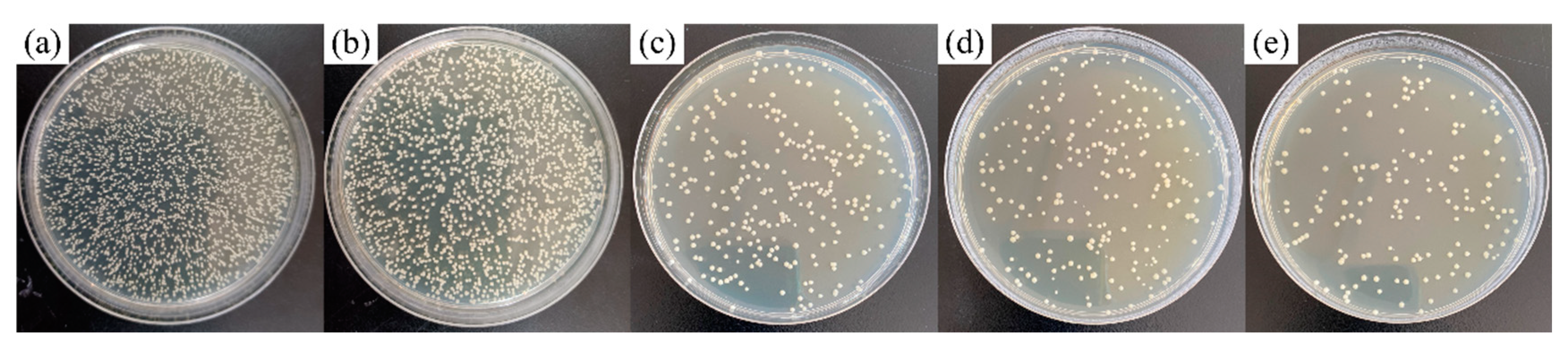
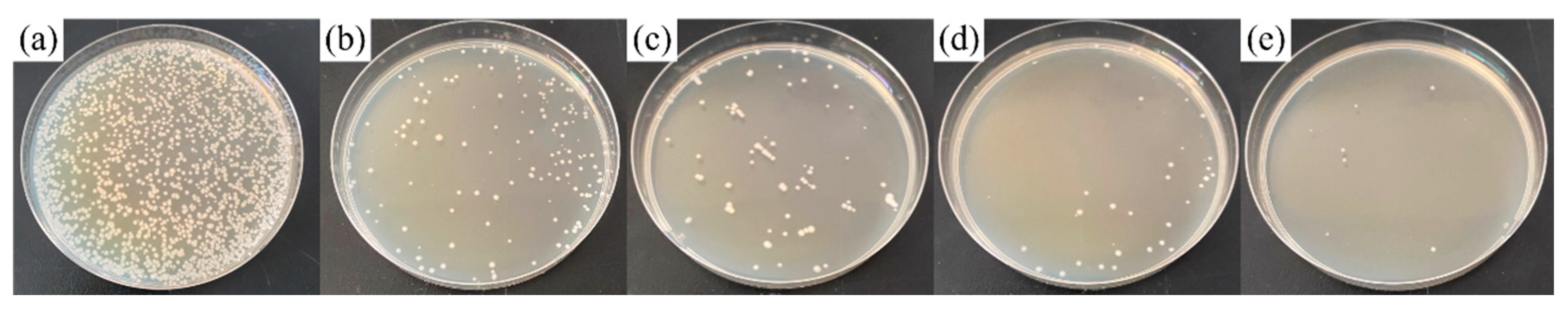
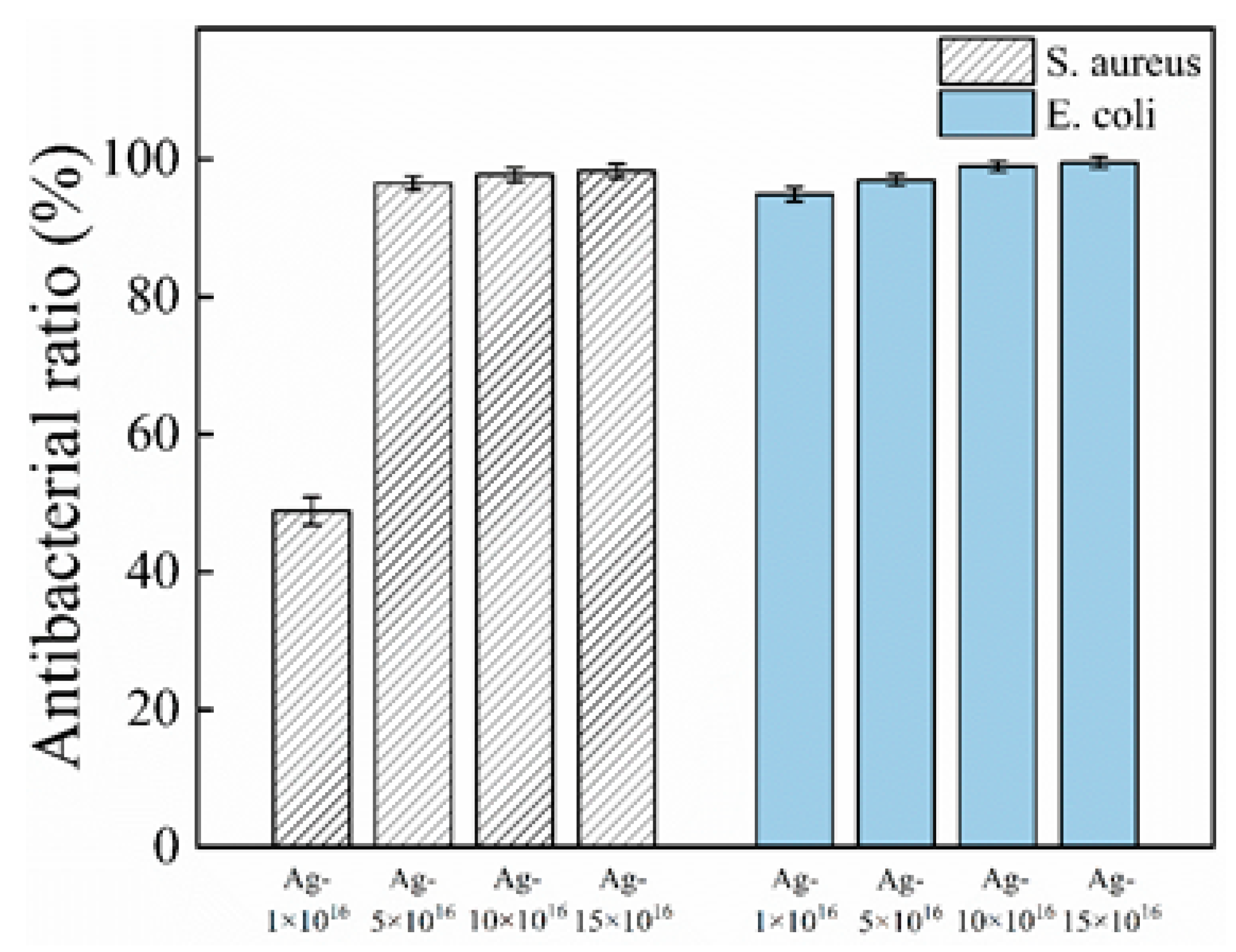
3.3. Antibacterial Performance

Antibacterial coatings have been widely explored to prohibit the earlier stages of bacterial adhesion, since biofilms are hard to remove after formation. Hence, it is critical to prevent early bacterial adhesion. To evaluate the antibacterial activity of Ag-implanted specimens, the bacterial were detached from the sample surfaces and dropped on agar to cultivate for 24 h, and then the number of colonies was counted. In general, a high initial antibacterial rate (more than 95%) could indicate excellent antibacterial activity [28]. Figure 10 and Figure 11 show the cultivation of the S. aureus and E. coli on agar for different specimens, respectively. The calculated antibacterial rates based on un-implanted TiNb-based alloy are shown in Figure 12.
It can be clearly seen that Ag-implanted samples obviously inhibit the growth of the S. aureus and E. coli, especially for specimens with higher content of sliver. Indeed, the corresponding antibacterial rate is approximately 98% for S. aureus and 99% for E. coli as the dose of silver ions amount to 10 × 1016 ions/cm2, respectively. Usually, the antibacterial effect of Ag-containing coatings depends on the effectiveness of the release of silver ions. While in this article, except for the antibacterial mechanism of silver ions release, the dispersed silver nanoparticles on the surface also provide the contact antimicrobial mechanism. Here, the Schottky–Mott theory [29] can be used to explain the interfacial behavior between silver nanoparticles and oxide phases (TiO2 and Nb2O5) on the surface of matrix. The silver nanoparticles on the surface will form a Schottky interface with the oxide phases interface, so that the electrons can only be conducted from the oxide phase to elemental silver, causing the silver nanoparticles to have the ability to “collect electrons”, which can capture the electrons emitted by the nearby bacteria, so as to generate a large number of holes on the surface of oxide phases. At the same time, the Schottky barrier prevents the recombination of electron holes, bringing about higher oxidability for the surface of oxide phases. On the one hand, this structure blocks the electron transmission of bacteria and hinders their life activities. On the other hand, the highly oxidizing surface of oxide phases can react with the cell wall of the bacterium, leading the cell wall to rupture, and killing the bacterium.

4. Conclusions

In this paper, the metal vapor vacuum arc (MEVVA) ion implantation technology, with extremely high kinetic energy, was applied to implant the silver element on the surface of TiNb alloy, bringing out the change of the microstructures and morphologies for the surface of substrate. It was found that the Ag elements were uniformly distributed on the surface after ion implantation and the diffusely distributed nanoparticles on the outermost surface were the silver nanoparticles. Meanwhile, the Ag element existed as solid-solution state in the implanted layer.
From the TEM analyses, the depth of the Ag-implanted layer was about 40 nm, and the amorphous structure (disordered structure), nanocrystalline structure and crystal structure (long range order) appeared respectively from the surface to the inside, illustrating that the degree of crystal order gradually increased. Thereinto, the region of the implanted layer was mainly constituted of nanocrystalline structures. The nanocrystalline strengthening effect formed by high-energy ion bombardment and the solid solution strengthening effect of silver atoms had made contributions to the increase of surface comprehensive mechanical properties, including the surface hardness and elastic modulus.
Finally, the suitable Ag-implanted specimen can obtain excellent antibacterial activity. Except for the antibacterial mechanism of silver ions release, the dispersed silver nanoparticles on the surface also provide the contact antimicrobial mechanism, which is the Schottky barrier–dependent antimicrobial efficacy of silver nanoparticles.

Author Contributions

Conceptualization, T.T.; methodology, T.T.; validation, F.L., K.Y. and B.D.; resources, P.Z. and D.W.; writing—original draft preparation, T.T.; writing—review and editing, B.D., K.Y. and F.L. All authors have read and agreed to the published version of the manuscript.

Funding

This research was funded by Natural Science Foundation for Excellent Young Scientists of Jiangsu Province, China (Grant No. BK20180068); China Postdoctoral Science Foundation funded project (Grant No. 2018M630555); Opening Project of Materials Preparation and Protection for Harsh Environment Key Laboratory of Ministry of Industry and Information Technology (Grant No. XCA20013-1); Opening Project of Jiangsu Key Laboratory of Advanced Structural Materials and Application Technology (Grant No. ASMA201701); the Fundamental Research Funds for the Central Universities, China (Grant No. NS2018039).

Institutional Review Board Statement

Not applicable.

Informed Consent Statement

Not applicable.

Data Availability Statement

Not applicable.

Conflicts of Interest

The authors declare no conflict of interest.

References

  1. Geetha, M.; Singh, A.K.; Asokamani, R.; Gogia, A.K. Ti based biomaterials, the ultimate choice for orthopaedic implants-A review. Prog. Mater. Sci. 2009, 54, 397–425. [Google Scholar] [CrossRef]
  2. Niinomi, M. Mechanical biocompatibilities of titanium alloys for biomedical applications. J. Mech. Behav. Biomed. Mater. 2008, 1, 30–42. [Google Scholar] [CrossRef]
  3. Long, M.; Rack, H.J. Titanium alloys in total joint replacement-a materials science perspective. Biomaterials 1998, 19, 1621–1639. [Google Scholar] [CrossRef]
  4. Gepreel, M.A.H.; Niinomi, M. Biocompatibility of Ti-alloys for long-term implantation. J. Mech. Behav. Biomed. Mater. 2013, 20, 407–415. [Google Scholar] [CrossRef]
  5. Niinomi, M.; Hattori, T.; Morikawa, K.; Kasuga, T.; Suzuki, A.; Fukui, H.; Niwa, S. Development of low rigidity beta-type titanium alloy for biomedical applications. Mater. Trans. 2002, 43, 2970–2977. [Google Scholar] [CrossRef] [Green Version]
  6. Hao, Y.L.; Yang, R.; Niinomi, M.; Kuroda, D.; Zhou, Y.L.; Fukunaga, K.; Suzuki, A. Aging response of the Young’s modulus and mechanical properties of Ti-29Nb-13Ta-4.6Zr for biomedical applications. Metall. Mater. Trans. A 2003, 34, 1007–1012. [Google Scholar] [CrossRef]
  7. Costerton, J.W.; Stewart, P.S.; Greenberg, E.P. Bacterial biofilms: A common cause of persistent infections. Science 1999, 284, 1318–1322. [Google Scholar] [CrossRef] [PubMed] [Green Version]
  8. Neoh, K.G.; Hu, X.F.; Zheng, D.; Kang, E.T. Balancing osteoblast functions and bacterial adhesion on functionalized titanium surfaces. Biomaterials 2012, 33, 2813–2822. [Google Scholar] [CrossRef] [PubMed]
  9. Monteiro, D.R.; Gorup, L.F.; Takamiya, A.S.; Ruvollo-Filho, A.C.; Camargo, E.R.D.; Barbosa, D.B. The growing importance of materials that prevent microbial adhesion: Antimicrobial effect of medical devices containing silver. Int. J. Antimicrob. Agents 2009, 34, 103–110. [Google Scholar] [CrossRef] [PubMed]
  10. Eckhardt, S.; Brunetto, P.S.; Gagnon, J.; Priebe, M.; Giese, B.; Fromm, K.M. Nanobio silver: Its interactions with peptides and bacteria, and its uses in medicine. Chem. Rev. 2013, 113, 4708–4754. [Google Scholar] [CrossRef] [Green Version]
  11. Marambio-Jones, C.; Hoek, E.M.V. A review of the antibacterial effects of silver nanomaterials and potential implications for human health and the environment. J. Nanopart. Res. 2010, 12, 1531–1551. [Google Scholar] [CrossRef]
  12. Gunawan, C.; Teoh, W.Y.; Marquis, C.P.; Lifia, J.; Amal, R. Reversible antimicrobial photoswitching in nanosilver. Small 2009, 5, 341–344. [Google Scholar] [CrossRef] [PubMed]
  13. Hu, G.S.; Jin, W.X.; Chen, Q.Y.; Cai, Y.C.; Zhu, Q.H.; Zhang, W.Z. Antibacterial activity of silver nanoparticles with different morphologies as well as their possible antibacterial mechanism. Appl. Phys. A Mater. Sci. Process. 2016, 122, 874. [Google Scholar] [CrossRef]
  14. Qin, Y.; Cheng, L.; Li, R.Y.; Liu, G.C.; Zhang, Y.B.; Tang, X.F.; Wang, J.C.; Liu, H.; Qin, Y.G. Potential antibacterial mechanism of silver nanoparticles and the optimization of orthopedic implants by advanced modification technologies. Int. J. Nanomed. 2018, 13, 3311–3327. [Google Scholar]
  15. Damm, C.; Munstedt, H. Kinetic aspects of the silver ion release from antimicrobial polyamide/silver nanocomposites. Appl. Phys. A 2008, 91, 479–486. [Google Scholar] [CrossRef]
  16. Neal, A.L. What can be inferred from bacterium-nanoparticle interactions about the potential consequences of environmental exposure to nanoparticles? Ecotoxicology 2008, 17, 362–371. [Google Scholar] [CrossRef] [PubMed]
  17. Zhang, X.F.; Shen, W.; Gurunathan, S. Silver nanoparticle-mediated cellular responses in various cell lines: An in vitro model. Int. J. Mol. Sci. 2016, 17, 1603. [Google Scholar] [CrossRef] [Green Version]
  18. Ahamed, M.; Karns, M.; Goodson, M.; Rowe, J.; Hussain, S.M.; Schlager, J.J.; Hong, Y.L. DNA damage response to different surface chemistry of silver nanoparticles in mammalian cells. Toxicol. Appl. Pharmacol. 2008, 233, 404–410. [Google Scholar] [CrossRef] [PubMed]
  19. Zhao, L.Z.; Chu, P.K.; Zhang, Y.M.; Wu, Z.F. Antibacterial coatings on titanium implants. J. Biomed. Mater. Res. Part B 2009, 91, 470–480. [Google Scholar] [CrossRef]
  20. Cao, H.L.; Liu, X.Y.; Meng, F.H.; Chu, P.K. Biological actions of silver nanoparticles embedded in titanium controlled by micro-galvanic effects. Biomaterials 2011, 32, 693–705. [Google Scholar] [CrossRef]
  21. Qiao, S.; Cao, H.; Zhao, X.; Lo, H.; Zhuang, L.; Gu, Y.; Shi, J.; Liu, X.; Lai, H. Ag-plasma modification enhances bone apposition around titanium dental implants: An animal study in Labrador dogs. Int. J. Nanomed. 2015, 10, 653–664. [Google Scholar]
  22. Wan, Y.Z.; Raman, S.; He, F.; Huang, Y. Surface modification of medical metals by ion implantation of silver and copper. Vacuum 2007, 81, 1114–1118. [Google Scholar] [CrossRef]
  23. Cao, H.L.; Tang, K.W.; Liu, X.Y. Bifunctional galvanics mediated selective toxicity on titanium. Mater. Horiz. 2018, 5, 264–267. [Google Scholar] [CrossRef]
  24. Kumar, N.; Kataria, S.; Dash, S.; Srivastava, S.K.; Das, C.R.; Chandramohan, P.; Tyagi, A.K.; Nair, K.G.M.; Raj, B. Tribological properties of nitrogen ion implanted steel. Wear 2012, 274–275, 60–67. [Google Scholar] [CrossRef]
  25. Wang, H.W.; Yang, D.Z.; Shi, W.D.; Patu, S. High cycle fatigue life improvement of polycrystalline alpha-iron modified by silver, chromium, aluminium, and yttrium ion implantation. Scr. Metall. Mater. 1995, 32, 2001–2007. [Google Scholar] [CrossRef]
  26. Pouilleau, J.; Devilliers, D.; Garrido, F.; Durand-Vidal, S.; Mahe, E. Structure and composition of passive titanium oxide films. Mater. Sci. Eng. B 1997, 47, 235–243. [Google Scholar] [CrossRef]
  27. Battiato, A.; Lorusso, M.; Bernardi, E.; Picollo, F.; Bosia, F.; Ugues, D.; Zelferino, A.; Damin, A.; Baima, J.; Pugno, N.M.; et al. Softening the ultra-stiff: Controlled variation of Young’s modulus in single-crystal diamond by ion implantation. Acta Mater. 2016, 116, 95–103. [Google Scholar] [CrossRef] [Green Version]
  28. Liu, Y.; Zheng, Z.; Zara, J.N.; Hsu, C.; Soofer, D.E.; Lee, K.S.; Siu, R.K.; Miller, L.S.; Zhang, X.L.; Carpenter, D.; et al. The antimicrobial and osteoinductive properties of silver nanoparticle/poly (DL-lactic-co-glycolic acid)-coated stainless steel. Biomaterials 2012, 33, 8745–8756. [Google Scholar] [CrossRef] [PubMed]
  29. Wang, M.L.; Cao, H.L.; Meng, F.H.; Zhao, X.B.; Ping, Y.X.; Lu, X.Y.; Liu, X.Y. Schottky barrier dependent antimicrobial efficacy of silver nanoparticles. Mater. Lett. 2016, 179, 1–4. [Google Scholar] [CrossRef]
Figure 1. The SEM morphology and element compositions of Ti-45Nb alloy: (a) SEM, (b) EDS, (c) Ti-Mapping, (d) Nb-Mapping; (e) X-ray diffraction pattern of Ti-45Nb alloy; (f,g) TEM image of Ti-45Nb alloy and the selected area diffraction pattern.
Coatings 11 01213 g001
Figure 2. The surface morphologies of TiNb alloy implanted by different doses of silver ions: (a1,a2) Ag-1 × 10¹⁶ ions/cm2, (b1,b2) Ag-5 × 10¹⁶ ions/cm2, (c1,c2) Ag-10 × 1016 ions/cm2, and (d1,d2) Ag-15 × 1016 ions/cm2.
Coatings 11 01213 g002
Figure 3. The surface element composition of TiNb alloy implanted by different doses of silver ions: (a) Ag-1 × 10¹⁶ ions/cm2, (b) Ag-5 × 10¹⁶ ions/cm2, (c) Ag-10 × 1016 ions/cm2, and (d) Ag-15 × 1016 ions/cm2.
Coatings 11 01213 g003
Figure 4. Grazing incident X-ray diffraction pattern (incident Angle was 0.1°) of the Ag-implanted layer with dose of 10 × 1016 ions/cm2.
Coatings 11 01213 g004
Figure 5. XPS depth distribution map of each element in the Ag-implanted layer: (a,b) XPS spectra of Ti-2p, (c,d) XPS spectra of Nb-3d, and (e,f) XPS spectra of Ag-3d.
Coatings 11 01213 g005
Figure 6. TEM image of the cross section for Ag-implanted layer and the mapping images of the contained elements (Ti, Nb, and Ag elements).
Coatings 11 01213 g006
Figure 7. The TEM bright field images of the cross section for Ag-implanted layer and the diffraction pattern of corresponding selection: (a,df) the TEM bright field images; (b,c) the selected area and its corresponding diffraction pattern.
Coatings 11 01213 g007
Figure 8. High resolution TEM (HR-TEM) images and Fourier transform images for four different regions of Ag-implanted layer from surface to inside: (a1–a3) HR-TEM images and Fourier transform image for Region I; (b1–b3) HR-TEM images and Fourier transform image for Region II; (c1–c3) HR-TEM images and Fourier transform image for Region III; (d1–d3) HR-TEM images and Fourier transform image for Region IV.
Coatings 11 01213 g008
Figure 9. (a) The curve of the displacement and load for the substrate and different doses of Ag-implanted specimens; (b) the surface hardness and elastic modulus for substate and different doses of Ag-implanted specimens; (c) the H/E and H3/E2 for substate and different doses of Ag-implanted specimens.
Coatings 11 01213 g009
Figure 10. Typical photos of the re-cultivated S. aureus colonies on agar for different samples: (a) Substrate; (b) Ag-1 × 10¹⁶ ions/cm2; (c) Ag-5 × 10¹⁶ ions/cm2; (d) Ag-10 × 1016 ions/cm2; (e) Ag-15 × 1016 ions/cm2.
Coatings 11 01213 g010
Figure 11. Typical photos of the re-cultivated E. coli colonies on agar for different samples: (a) Substrate; (b) Ag-1×10¹⁶ ions/cm2; (c) Ag-5×10¹⁶ ions/cm2; (d) Ag-10×1016 ions/cm2; (e) Ag-15×1016 ions/cm2.
Coatings 11 01213 g011
Figure 12. Antibacterial ratios of the re-cultivated S. aureus and E. coli colonies on agar for different doses of Ag-implanted specimens.
Coatings 11 01213 g012
Publisher’s Note: MDPI stays neutral with regard to jurisdictional claims in published maps and institutional affiliations.

