Article

Evaluation of Adhesion Properties of Hard Coatings by Means of Indentation and Acoustic Emission

1
Faculty of Material Science and Technology, Institute of Material Science, Slovak University of Technology in Bratislava, Jána Bottu 25, 917 24 Trnava, Slovakia
2
CRM Group-CRM, 4000 Liège, Belgium
3
ZD Rpety-Dakel, Ohrobecká 408/3, 142 00 Praha, Czech Republic
*
Author to whom correspondence should be addressed.
Coatings 2021, 11(8), 919; https://doi.org/10.3390/coatings11080919
Submission received: 18 June 2021 / Revised: 26 July 2021 / Accepted: 27 July 2021 / Published: 31 July 2021

Abstract

:
In general, the mechanical properties of hard thin coatings are investigated using indentation methods. Material characteristics of hard coatings, such as elastic modulus and hardness, are evaluated by means of nanoindentation and an appropriate evaluation methodology. The most popular method used to obtain the coating properties required using nanoindentation is the evaluation based on the Oliver and Pharr methodology. Adhesion and wear properties can be calculated using these data. In this study, we used a novel method to evaluate the wear and adhesion of coatings. A special measuring device combined with static indentation and acoustic emission signal detection was developed to evaluate the adhesion of coatings. The device consists of a macrohardness instrumental indentation device equipped with an acoustic emission measuring gauge. It was used to investigate crack formation and adhesion of coatings deposited on different substrates using acoustic emissions data. The results using both the existing and novel methods were compared and evaluated.

1. Introduction

The quality of coated mechanical components mainly depends on the quality of the coating–substrate system. If the coating fails, the functions of the mechanical components can be significantly impaired. This is particularly important for deposited coatings used to increase the mechanical resistance of machine tools. The most important parameter influencing the coating lifetime under load is the quality of the bonding or adhesion between the substrate and coating. Adhesion is defined as a state when two surfaces are bonded together by an inter-layer [1]. The adhesion of coatings to substrates is one of the most important parameters used for thin layer quality evaluation.
The connection between the coating and its substrate is improved when the mutual solubility of the coating and substrate components in the solid state allows the formation of a thin diffusion layer at the coating–substrate interface. Adhesion is a critical component of the coating–substrate system. The adhesion of coatings depends on the purity of the substrate, surface finishing (less roughness leads to better adhesion), and the difference in ductility of the substrate and the layer. Satisfactory values of adhesion significantly affect the interfacial strength, since it prevents cracking, spalling, and delamination of the layer. Therefore, knowledge of the type of damage and cracking of the thin film is an important consideration when evaluating the mechanical properties of the coating–substrate system [2].
However, one of the most popular methods for analyzing the coating–substrate system adhesion is indentation. Indentation enables the usage of an easy loading configuration and the possibility to directly observe crack formation and film delamination. During the loading stage, both the coating and substrate accomplish the deformation imposed by the indenter. However, during unloading, the coating is usually harder, and thus the elastic recovery is higher, which means adhesion forces between the substrate and coating are not strong enough to avoid delamination [3].
The adhesion of hard coatings depends on mechanical properties such as elastic modulus, E; hardness, H; and fracture toughness ,   K I c [4]. These mechanical parameters are calculated from data obtained by nanoindentation tests.
The formation of fractures and their propagation in hard coatings is commonly investigated using indentation tests. Cracking patterns are formed as a function of the R/t ratio (where R is the radius of the tip and t is the coating thickness) [5]. Three main types of crack can be identified during indentation of hard coatings deposited on ductile substrates (Figure 1):
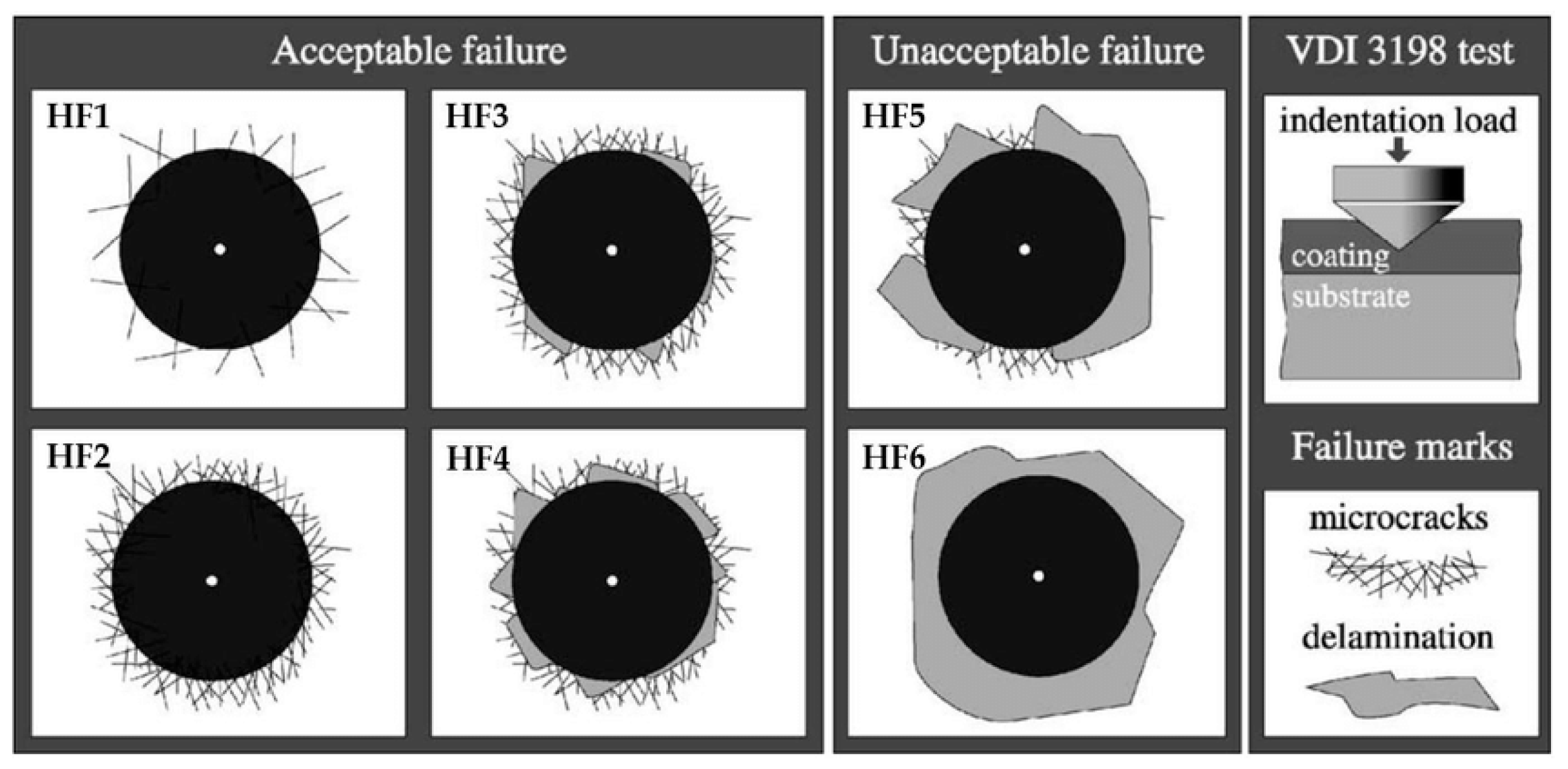
  • Circumferential cracks appear at the periphery of plastic zone;
  • Channel cracks are initiated under heavy stress caused by direct contact between the indenter and coating;
  • And radial cracks originate from the middle of the indentation imprint and propagate outwards in the form of beams [6,7].
If the loading force of the indenter is high enough and the substrate is plastically deformed, coatings begin to lose adhesion and delamination or spalling can occur. Cracking and spalling of hard coatings release dissipated energy [8] which propagates through the material in the form of elastic waves. Their formation can be detected by an acoustic emission (AE) measuring device.
The AE event caused by indentation is often explained by one of the following mechanisms as a function of the analysed specimen (ceramic, metal, semiconductor, monolayer, multilayer sample, etc.) and experimental conditions (time, temperature, geometry of the indenter, etc.):
  • Dislocations nucleation (sudden yielding of a material under load)
  • Rupture of a hard-brittle film on an elastic-plastic substrate [9];
  • Strain transfer across grain boundaries in metals [10,11];
  • Crack formation;
  • Phase transformation;
  • Amorphization and densification [12].
It is known that a failure mechanism has an influence on the detectability of AE. AE events start to occur when the stress caused by indentation exceeds certain limits, beyond which the energy is released.
The ISO 14577-1 standard [13] defines the terms nanoindentation, microindentation, and macroindentation according to the depth of the imprint and applied loads as follows:
  • Nanoindentation: h ≤ 0.2 µm;
  • Microindentation: F < 2 N, h > 0.2 µm;
  • Macroindentation: 2 N ≤ F ≤ 30 kN.
ISO 14577-4 [14] was especially addressed for coatings and thin films, since ISO 14577-1 was not developed with its focus on coatings and thin films. However, the behavior of viscoelastic materials tested by indentation was not covered yet by any of these documents [15].
However, it is possible to investigate crack formation and delamination of hard coatings after the indentation test by comparing the imprints observed using scanning electron microscopy with the failure chart according to VDI 3198 standard [16] (Figure 2).
A visual comparison can provide information about final failure of the coating–substrate system. However, no further information about the failure can be obtained during the indentation. The acoustic emission measurement system is able to continuously monitor and record acoustic data, which can be used for analysis after the test.
In this study, we performed a detailed investigation of material parameters of two different types of coating deposited on two different substrates. Material parameters measured and calculated using nanoindentation tests were compared with acoustic emission data measured during macroindentation tests.

2. Materials and Methods

2.1. Materials Selection

Two types of coating were investigated in the experiment. Both types were deposited onto the discs 12.5 mm in diameter and synthesized in company LISS (Rožnov pod Radhoštěm, Czech Republic) All samples were deposited by LARC (Lateral rotating cathodes) in a PLATIT π80 + DLC (PLATIT AG, Selzach, Switzerland) deposition unit on the following two different substrates: High-speed steel HSS 6-5-2-5 (1.3243) (HSS), and WC-6Co sintered carbide (SC).

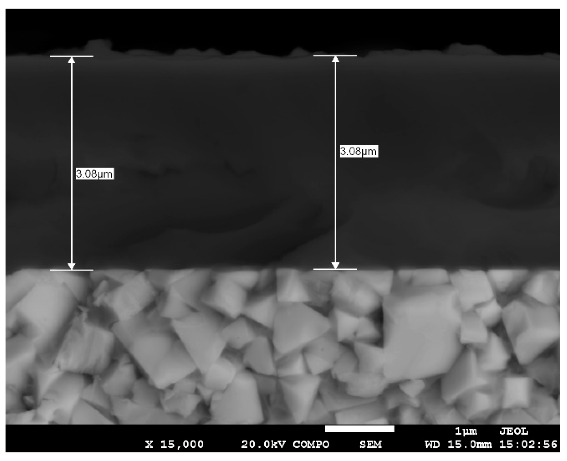
2.1.1. nACo3 Coating Characterization

Two samples with nanocomposite nACo3 coating were used; the first was deposited on the HSS substrate and the second on the SC substrate. nACo3 coating can be characterized by the following architecture: TiN-AlTiN-AlTiN/SiN [17]. The color of the coating is violet-blue and hardness ranged from 25 to 28 GPa. The entire thickness of the coating was around 3 µm.
nACo3 coating has a nanocomposite structure. The Si content is influenced by the deposition rate. Generally, in the case of a Ti-Si-Al-N coating, the Si and Al ions substitute Ti in the crystal lattice of c-TiN, reducing the coating’s lattice parameters. Nucleation and segregation of the amorphous Si3N4 phase present in the coating at a particular Si content causes suppression of the nc-(Ti, Al)N grain growth. This effect is accomplished by embedding nanocrystalline AlTiN grains into an amorphous Si 3 N 4 matrix [18,19].

2.1.2. TiXCo3 Coating Characterization

The second coating, TiXCo3, was deposited only on a high-speed steel (HS6-5-2-5, 1.3243) substrate. TiXCo3 is a nanocomposite coating with high silicon content and the following architecture of individual layers: TiN-nACo3-TiN/SiN. The addition of Si leads to phase segregation of an amorphous SiNx matrix that surrounds (nano)crystalline grains of the TiAlN phase [20]. These crystalline grains are embedded in an amorphous matrix and form a nanocomposite structure, generally designated as nc-MeAlN/a-SiNx. Compared to the previously mentioned coating, TiXCo is characterized by higher hardness (38 GPa), while its thickness is 3 µm. The incorporation of Si and Al atoms leads to a concurrent decrease in lattice parameters and internal stresses. Solid solution strengthening, which is associated with an increase in hardness, toughness, elastic modulus, and wear resistance can occur. The formation of a protective SiO2 layer improves the oxidation resistance. The addition of Si leads to the formation of nc-TiAlN and ornc-CrAlN grains in an amorphous SiNx matrix [17,21].
Both coatings we used here can be characterized by high hardness, excellent abrasive wear resistance, high reliability in dry machining, and low thermal conductivity.
The triple structure of the coatings enables thicker coatings to be deposited, which is extremely useful for cutting tools [22]. Figure 3 illustrates the cross-section of the nACo3 coating deposited on sintered carbide.

2.2. Measuring Methods

Coating properties were investigated using two indentation methods. The mechanical properties of the coatings were first determined by the nanoindentation method and then by the Daimler–Mercedes macroindentation method combined with the detection of acoustic emission signals.
Surface spalling and cracking of coatings after the indentation test were examined by the JEOL JSM 7600 F high resolution scanning electron microscope (HRSEM, JEOL, Tokio, Japan).

2.2.1. Nanoindentation

Nanoindentation tests were performed using a Nanoindenter Agilent G200 (Santa Clara, CA, USA) equipped with an indenter XP head Berkovich tip with a maximum indentation depth of 2 µm. A grid of 6 × 6 measurements were made at room temperature at an acquisition frequency of 10 Hz, with a strain rate of 0.05 s–1 for each specimen. We adopted the methodology and calculations from Oliver and Pharr [23,24], while the experimental method used was continuous stiffness measurement (CSM) mode at a frequency of 75 Hz and an amplitude of 0:5 nm. Load, displacement, and elastic contact stiffness were continuously recorded during indentation. The area function of the contact depth was carefully calibrated from measurements performed on a fused silica sample. The Young’s modulus of each sample was determined using equations from the procedure given by Oliver and Pharr, by taking a Poisson’s ratio of 0.3 for each sample and removing the elastic contribution of the indenter, which was made of diamond. The nanoindentation test parameters are summarized in Table 1.
The plasticity index ( H / E ) provides more information about wear properties and overall tribological behaviors of coatings [25,26]. A high H / E * value refers to a reduced contact pressure, since the applied load is distributed over a larger area [27]. According to Musil, hard coatings with H / E *   > 0.1 are particularly desirable for many tribological applications [28]. Another interesting index used in the elastic-plastic approach is the plastic deformation resistance ( H 3 / E 2 ) . This parameter is proportional to the resistance of the coating to plastic deformation [25]. This means that the higher the resistance to plastic deformation, the higher the H 3 / E 2 ratio . In general, a low E is desirable, as it allows the given load to be distributed over a wider area [28,29]. The following mechanical properties were calculated:
  • Elastic modulus (E) and hardness (H). Mean values of E and H were obtained at indentation depths 100 and 200 nm;
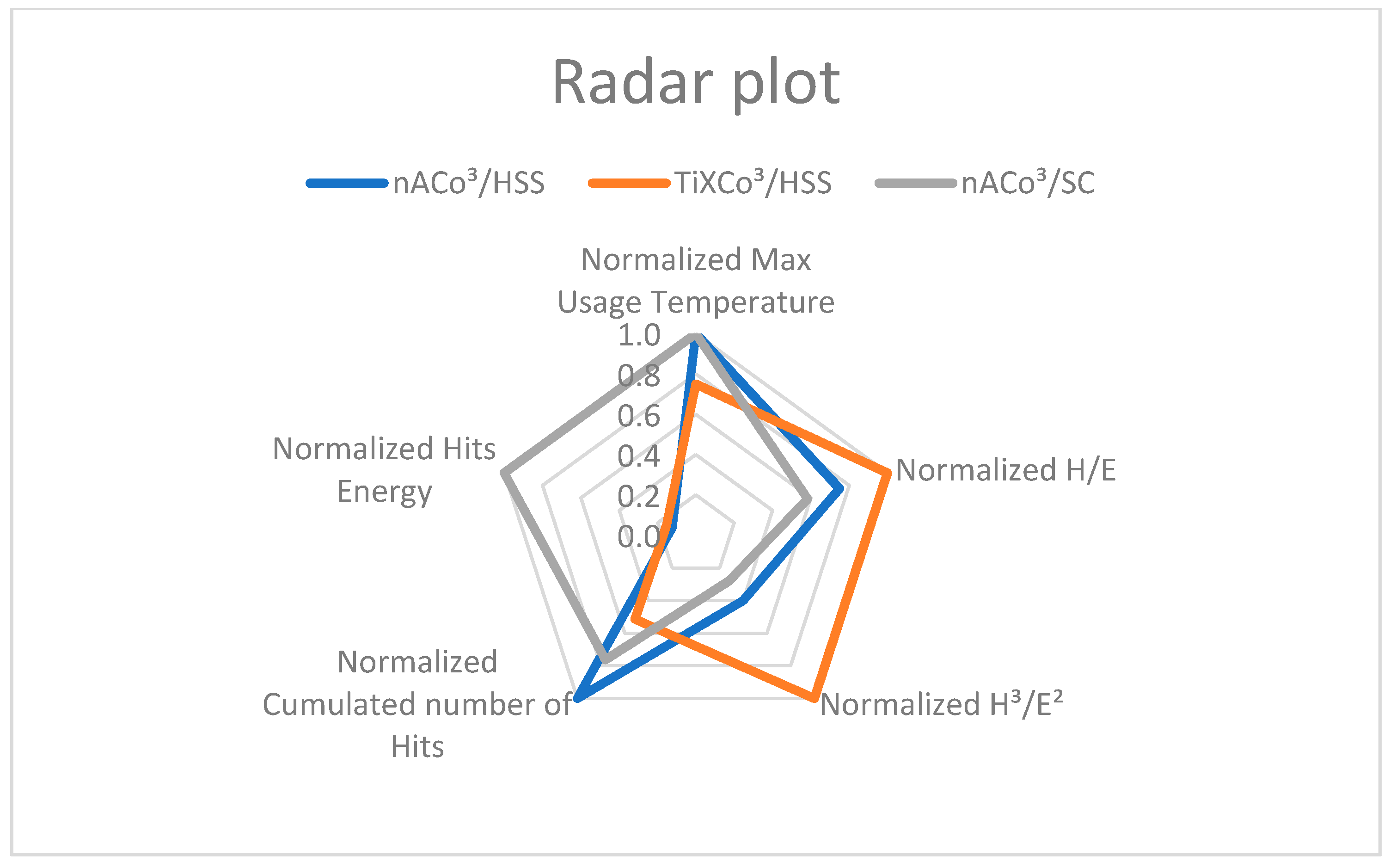
  • Plasticity index (H/E) and plastic deformation resistance (H3/E2).

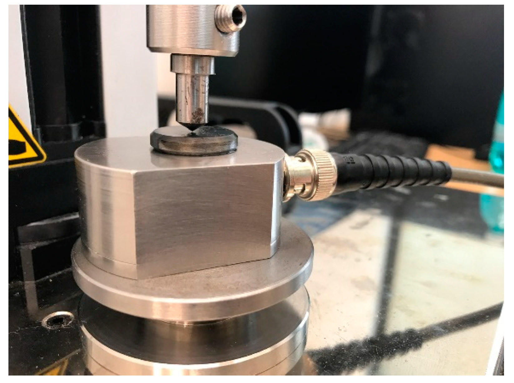
2.2.2. Macroindentation and AE Measuring

The popular Daimler–Mercedes indentation test, which is described in the VDI 3198 standard [30], serves as a basic destructive quality test for the evaluation of coated compound adhesion [16,31]. The loading force applied to the indenter generates an elastic and then a plastic deformation of the sample surface. When a coating breaks, crack initiation and propagation as well as spalling release energy, which propagates through the material in form of waves and they can be captured by AE sensor [32]. The AE signal is generated by fracture phenomena and can be measured and quantified with an acoustic emission gauge (ZD Rpety-DAKEL, Prague, Czech Republic). The analysis of these acoustic emission signals provides information about the adhesion and ductility of the coatings.
The advantages of this indentation method are the fast execution of tests using it, minimal demands on the measurement device, and the ability to monitor coating behavior with an acoustic emission device that can be attached directly to the tested specimens without damaging the sample.
A special measuring device for the acoustic emission signal detection and evaluation of coatings adhesion has been developed. This consists of a UMZ-3K (Micro-Epsilon, Bechyne, Czech Republic) device for the measurement of materials’ properties. The device is equipped with a Rockwell C indenter with a top angle of 120°. The movement of the indenter is stopped automatically when the adjusted force is reached.
Acoustic emission signals generated during the test were measured by a DAKEL-ZEDO device (ZD Rpety-DAKEL, Prague, Czech Republic), which is an advanced and powerful modular system for detecting and evaluating acoustic emission signals. In this case, a sophisticated, yet very simple AE sensor type Holder was used, which enables the testing of samples without a special fixing mechanism. This sensor facilitates the detection of coating cracks, spalling, and delamination. The coated sample mounted on the AE sensor is shown in Figure 4.
Two tests were performed using maximum forces of 50 and 1500 N. Wear and tribological properties of the substrate–coating system were evaluated.
The first test included a loading with constantly increasing force of 50 N. The second test used the maximum force of 1500 N. The indentation parameters of this test are summarized in Table 2. When the loading force reached 500 N, a 10 s dwell time was applied. The force was then increased to the maximum load of 1500 N (so-called “instrumented indentation”). First, the applied loads generated an elastic and then plastic deformation.
The most commonly used AE parameters for the evaluation of coating adhesion are as follows [32]:
  • Hit: a signal that exceeds the threshold and causes a system channel to accumulate data. It is frequently used to show the AE activity with counted number for a period or accumulated numbers. In general, one waveform corresponds to one “hit”. It represents the number of cracks and other structural instabilities that arose and grew in a specimen.
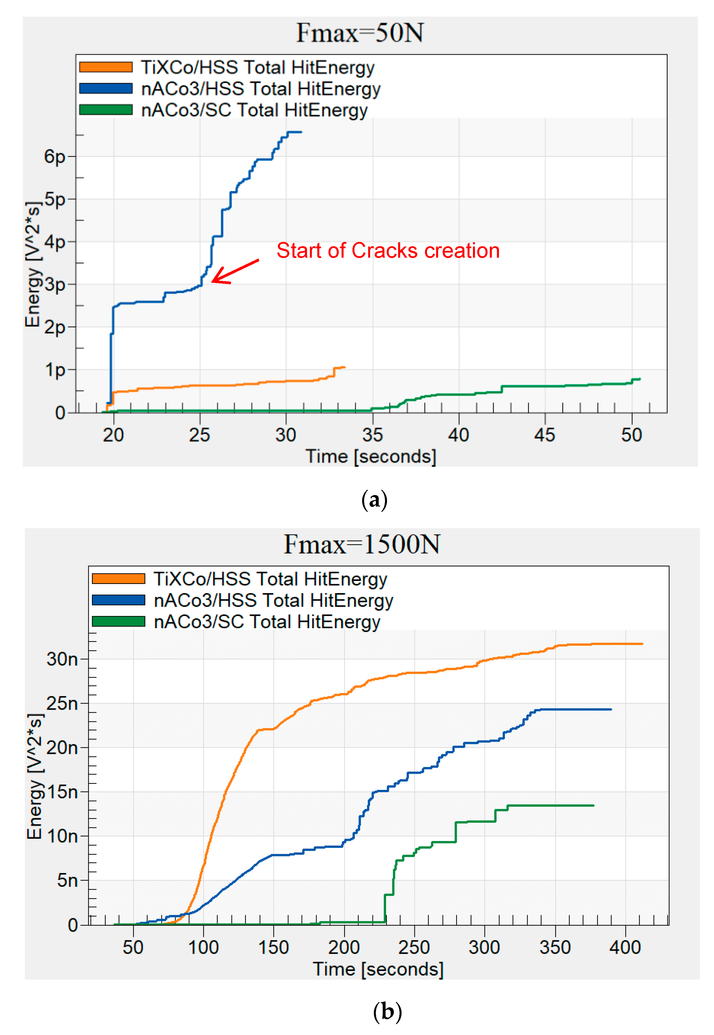
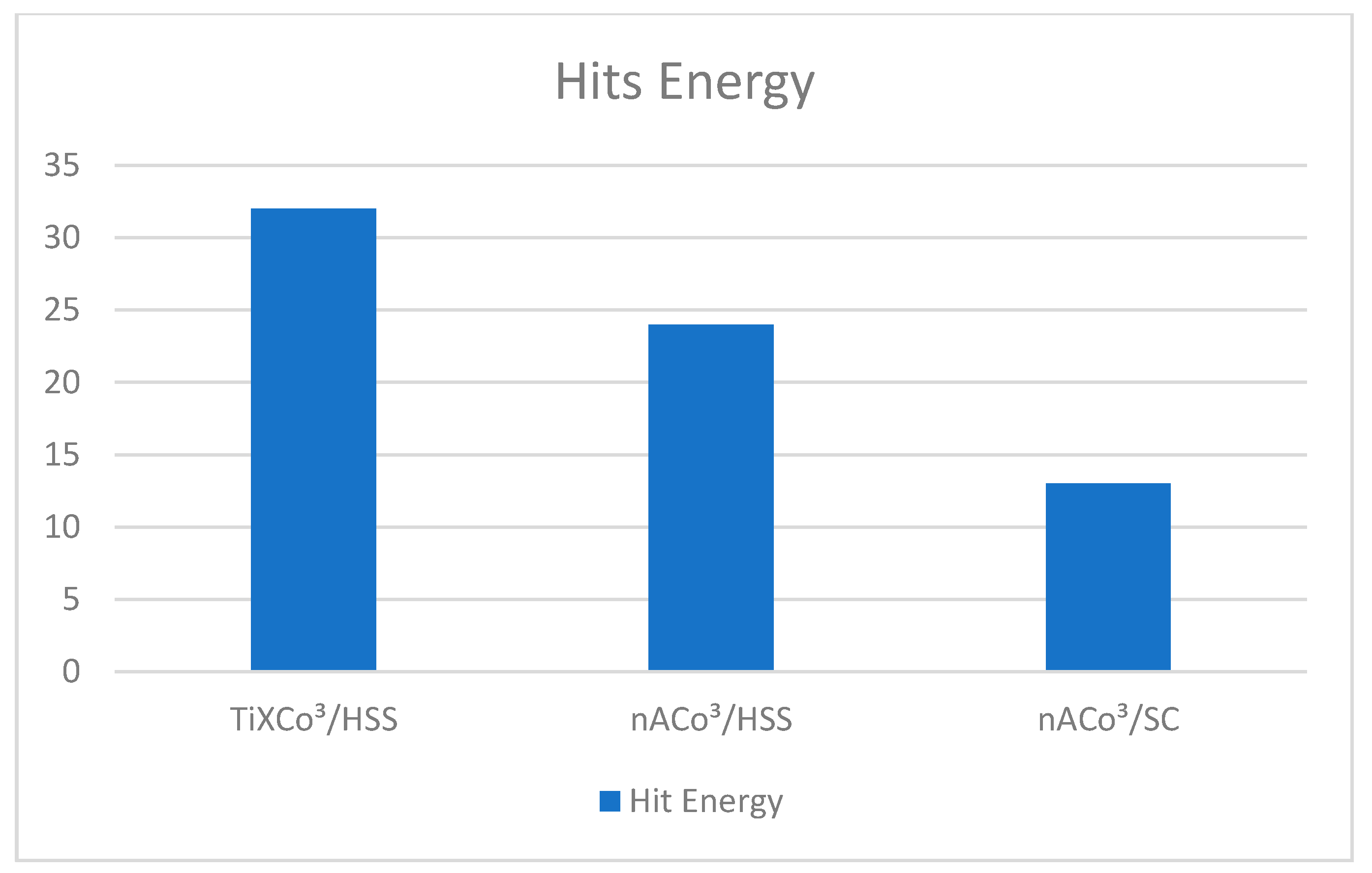
  • Hits energy is an integral of squared (or absolute) amplitude over time of signal duration. There are different approximations for AE signal energy (with units of V2·s), most frequently it is expressed in energy units (eu). According to previous studies there is relationship between fracture energy and AE signal energy, it gives information about the energy released into the material because of crack initiation and propagation [30]. More intense crack initiation causes more energy to be released. Usually, more energy is released when spalling or delamination in hard coatings occurs.
It is possible to set more thresholds and record more AE signals of different amplitudes within the AE system.

3. Results

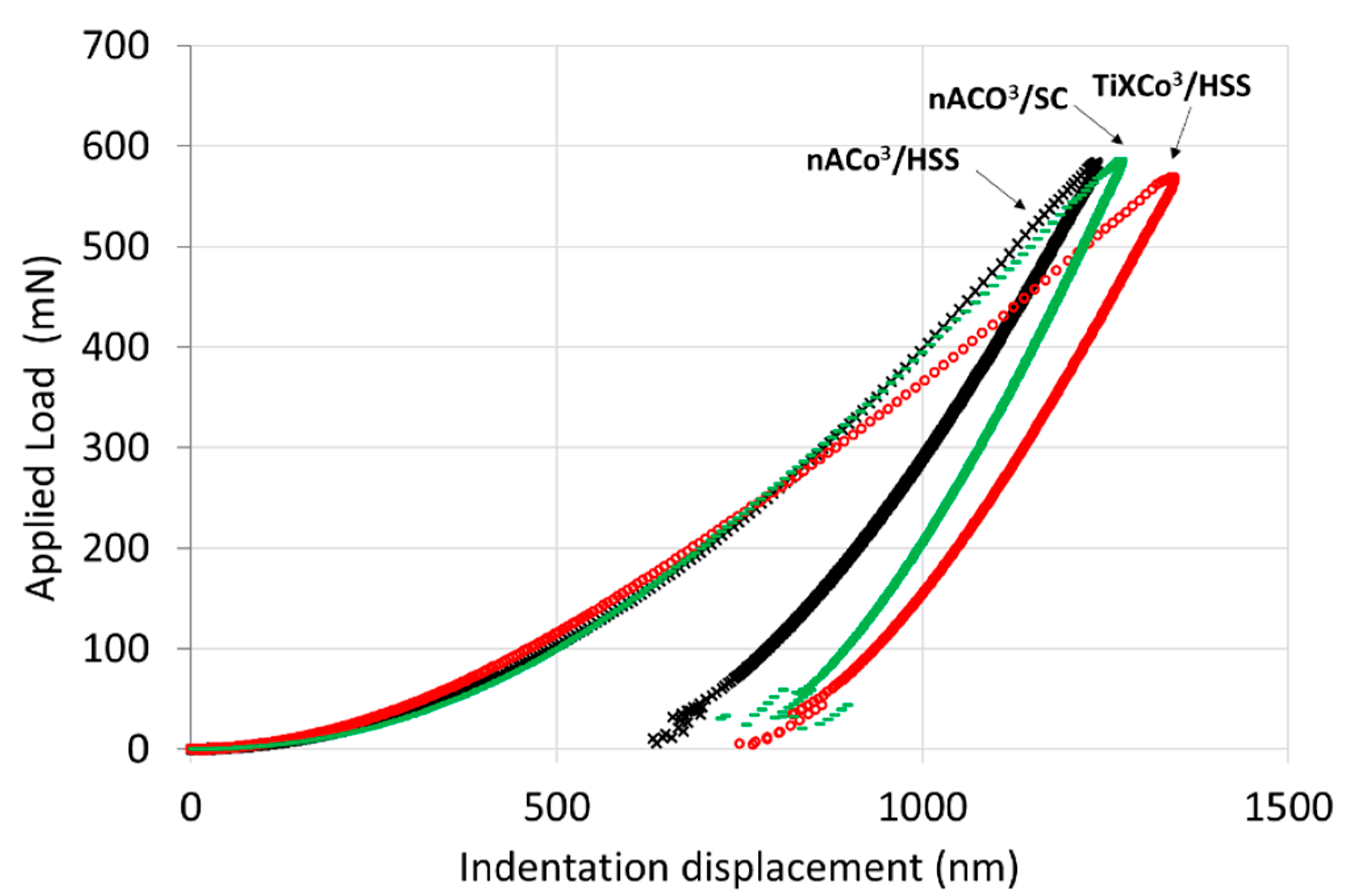
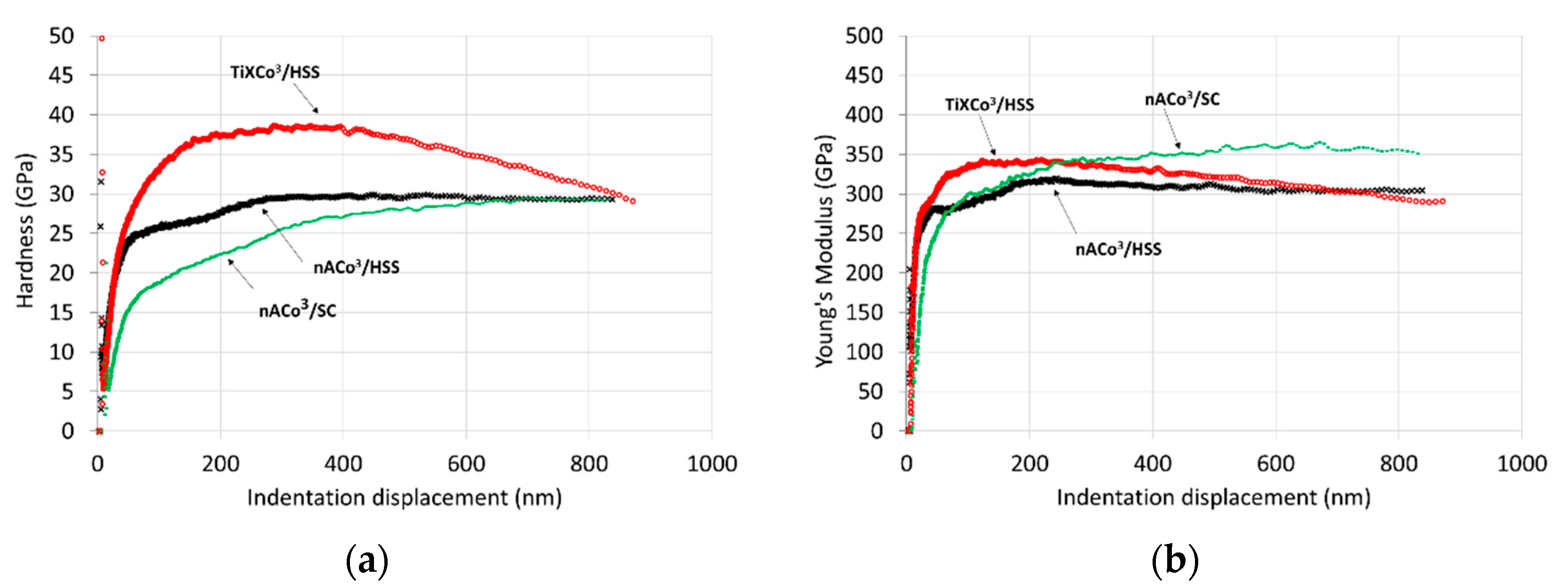
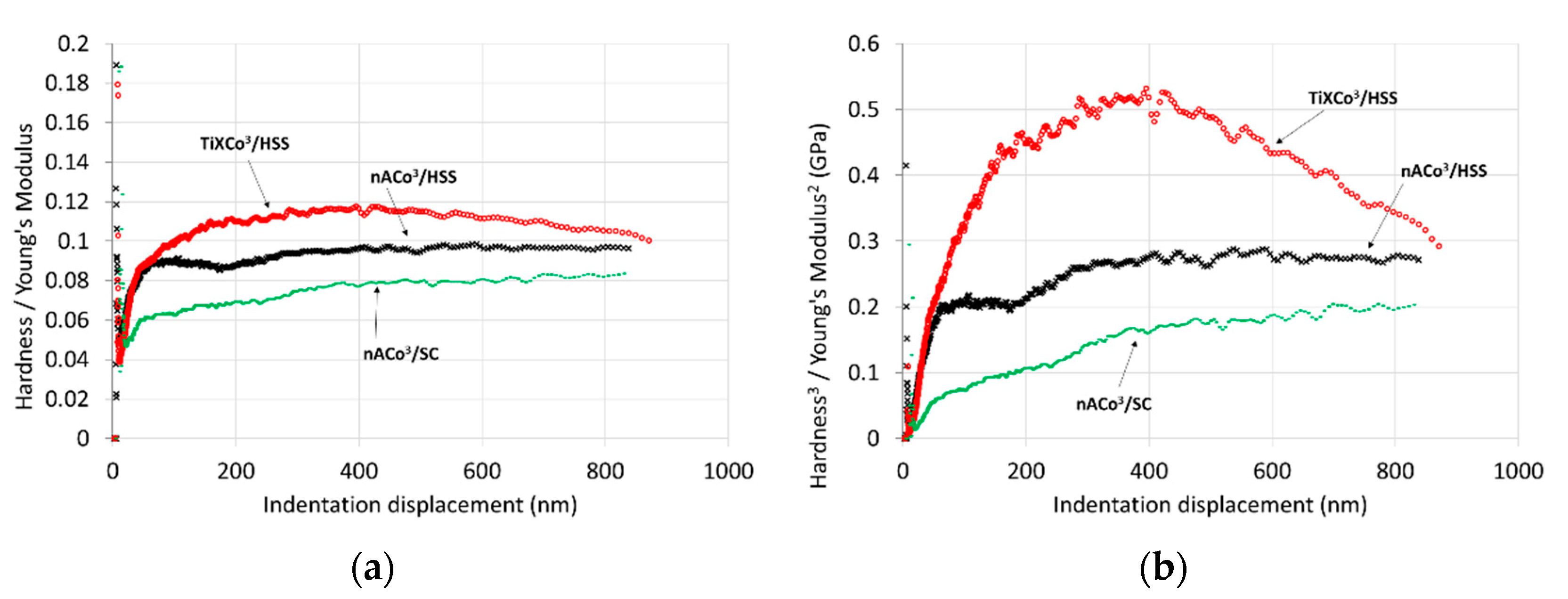
3.1. Nanoindentation

The nanoindentation tests were performed to determine the main material parameters, hardness H, and Young’s modulus. Both hardness and elastic modulus were calculated using the Oliver and Pharr method, which considers the projected area of the Berkovich indenter and the indentation contact depth.
Figure 5 shows the load-displacement curve of specimens deposited with nACo3 and TiXCo3 coatings, indicating the difference in behavior of the coatings.
Figure 6a shows the difference in coating hardness. A higher hardness H of TiXCo3 coating was documented at small depths. This effect was caused by the higher Si content in the top layer of the coating. By contrast, slightly higher hardness at higher depths was confirmed in the nACo3 coating deposited on sintered carbide.
The elastic module curves show different behavior (Figure 6b). There is a difference in the Young’s modulus for the same coating, nACo3, which is caused by the use of different substrates. A decrease in elastic modulus means that the coating exhibits better elastic properties and higher resistance to cracking. The TiXCo3 coating deposited on the high-speed steel (HSS) substrate had approximately the same values of elastic modulus as the nACo3 coating at higher indentation depths. The elastic modulus value was higher at low indentation depths and then began to decrease with the indentation depth. This could be caused by the increase in Si content, which usually leads to a decrease in the mean value of the elastic modulus.
Figure 7a,b shows the curves of the plasticity index, represented by the H / E   ratio , while plastic deformation resistance is represented by the H3/E2 ratio; the latter expresses the resistance of a material to plastic deformation and the probability of plastic deformation of hard coatings. Materials defined by high hardness and low elastic modulus have a high plastic deformation resistance.

3.2. Macroindentation and AE Measuring

The macroindentation test was performed to determine the resistance of the coatings to cracking, spalling, and delamination. However, to investigate the adhesion and wear parameters of the coatings, a high loading force is needed. Following this test, data from all substrate–coating systems must be compared. We assumed that the coatings’ tribological behavior depends on the substrate’s properties, as the substrate is plastically deformed by high loads, which significantly influences the results of coatings’ wear behavior.

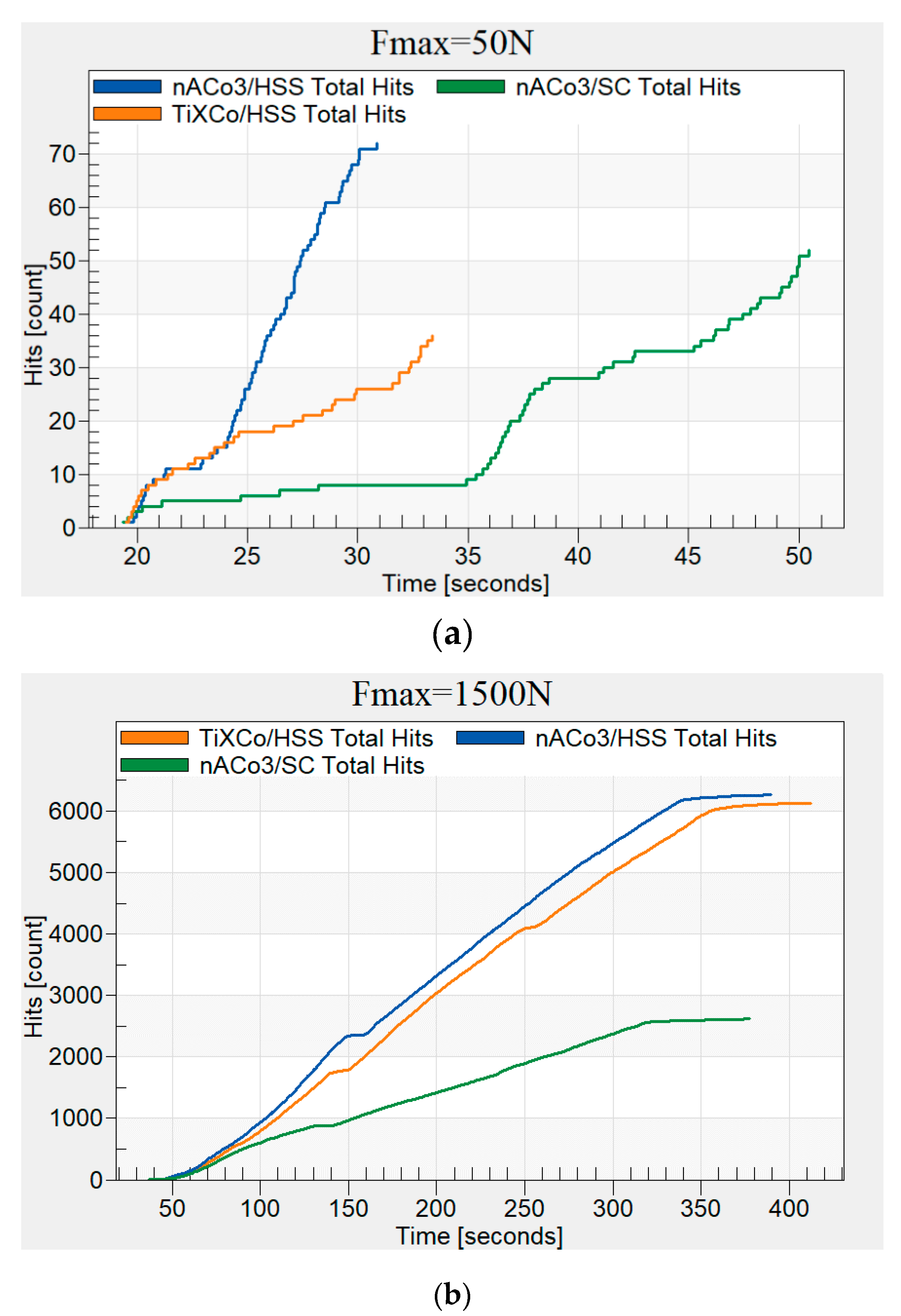
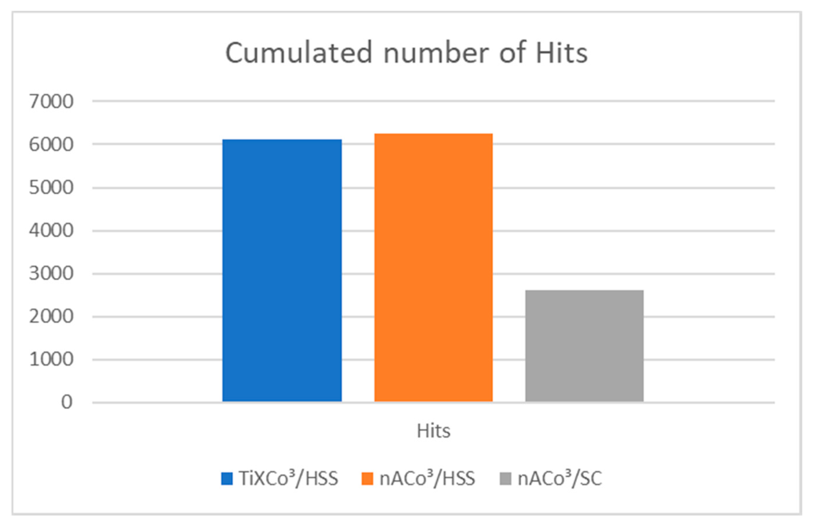
3.2.1. Number of Hits

The thresholds were adjusted to detect all of the AE events that occurred during the test. Thresholds were adjusted to slightly above ambient noise and then the measuring gauge was able to detect small energy dissipations into the measured material. Acoustic events represented by hits could be caused by different mechanisms mentioned in Section 1. However, they are mostly caused by the formation of cracks. The adjusted threshold level and chosen amplification are given in Table 3.
Figure 8 documents the results from the macroindentation test with the data recorded using AE.
Figure 8a shows the hits curves recorded during the macroindentation tests of all coating–substrate systems at a maximum load of 50 N. The hit parameter was adjusted to count every event which arose in the material during the indentation test. The threshold was set according to Table 3. Figure 8b illustrates the same hits curves. However, they were captured at a maximum load of 1500 N. We obtained different results from acoustic data recorded at different loads. A smaller number of hits was found in the nACo3 coating deposited on sintered carbide in both tests. This is related to the material properties of the substrate. As previously confirmed by nanoindentation, this coating had better resistance to plastic deformation than the other coating we tested (Figure 7). The nACo3 coating deposited on HSS substrate had most hits.
A higher loading force also influences the number of AE events. We suggest that this is caused by the substrate type, because sintered carbide is more resistant to plastic deformation. The area around the indentation imprint is not widely influenced by the indentation. The coating undergoes elastic deformation up to the brittle failure as a result of contact pressure caused by the indentation. Compared to HSS, the sintered carbide is deformed plastically at relatively high loads.

3.2.2. Hits Energy

The hits energy parameter is usually involved when the amount of energy dissipated into the material is under investigation. As mentioned before, when more energy is dissipated into the material it leads to higher amplitudes and longer durations of the events that are detected. This means that if larger cracks appear, or spalling of the coating occurs, more energy is dissipated. The creation of cracks and occurrence of spalling can commence at different loading forces. When the loading force exceeds the critical value then cracks and spalling start and can be detected by a hits energy curve. A hits energy curve can therefore be used to detect the loading force at which cracking and spalling occur. These material defects depend on the coating material behavior and properties of the coating–substrate system [33].
However, by using the hits energy parameter, it is possible to analyze every step of loading and estimate the volume of coating–substrate system damage from energy dissipation caused during indentation. The hits energy curves of all samples are given in Figure 9. Further observation revealed that the nACo3 coating deposited on HSS started to increase dissipated energy at relatively low loads compared to the other specimens. This coating also reached the highest total energy of all AE events. Figure 9b shows the hits energy curves of all coatings captured at the maximal force of 1500 N.
The values of the hits energy curve for the nACo3 coating deposited on sintered carbide (Figure 9b) were the lowest. The hits energy curve of the nACo3 coating deposited on HSS exhibited almost intermediate values. The TiXCo3 coating had the maximum value of hits energy of cracks identified by acoustic emission and most of this acoustic event caused by indentation was related to the creation of cracks which dissipated more energy. This is because when larger cracks are created, more energy is dissipated into the material.

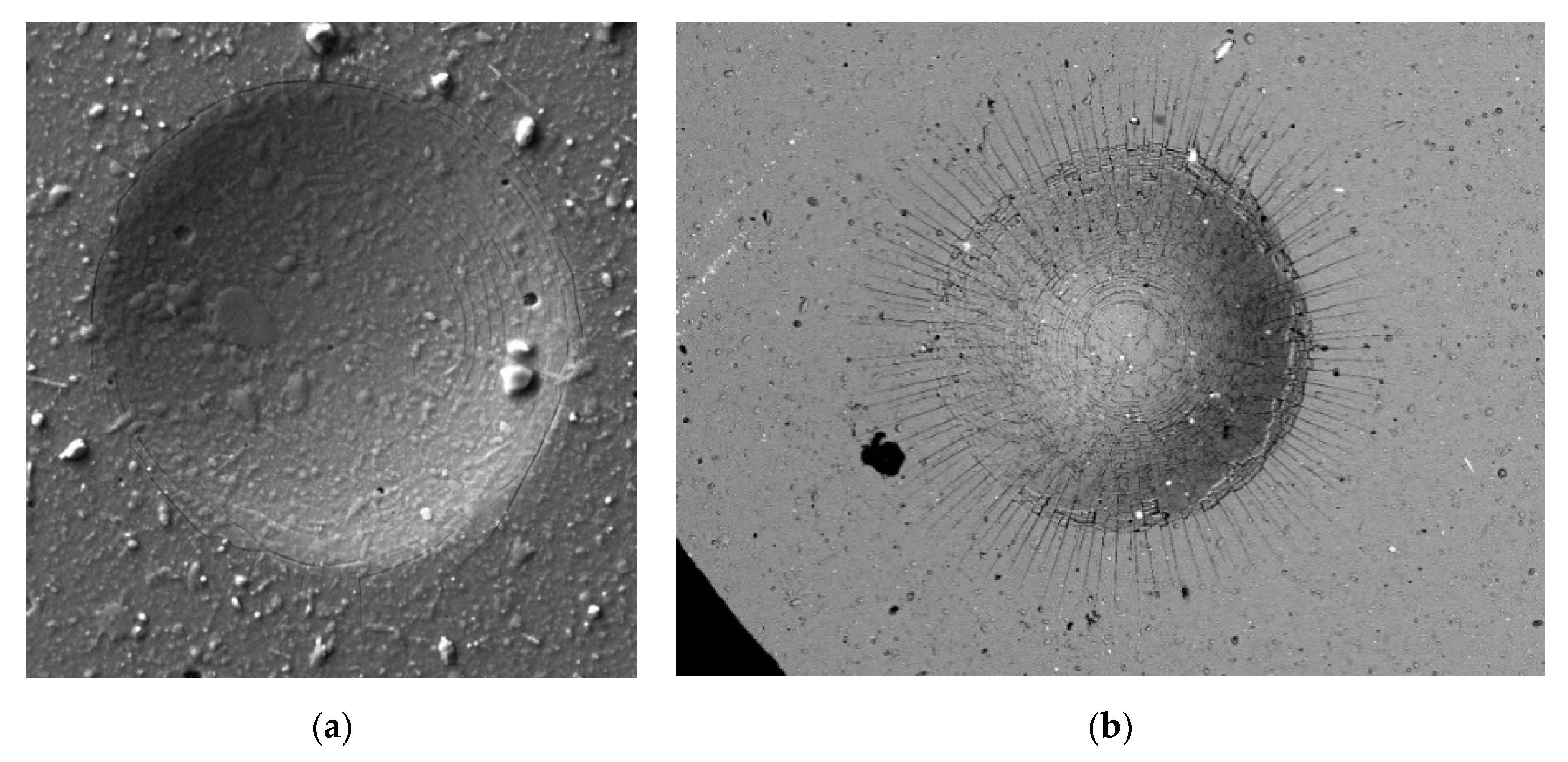
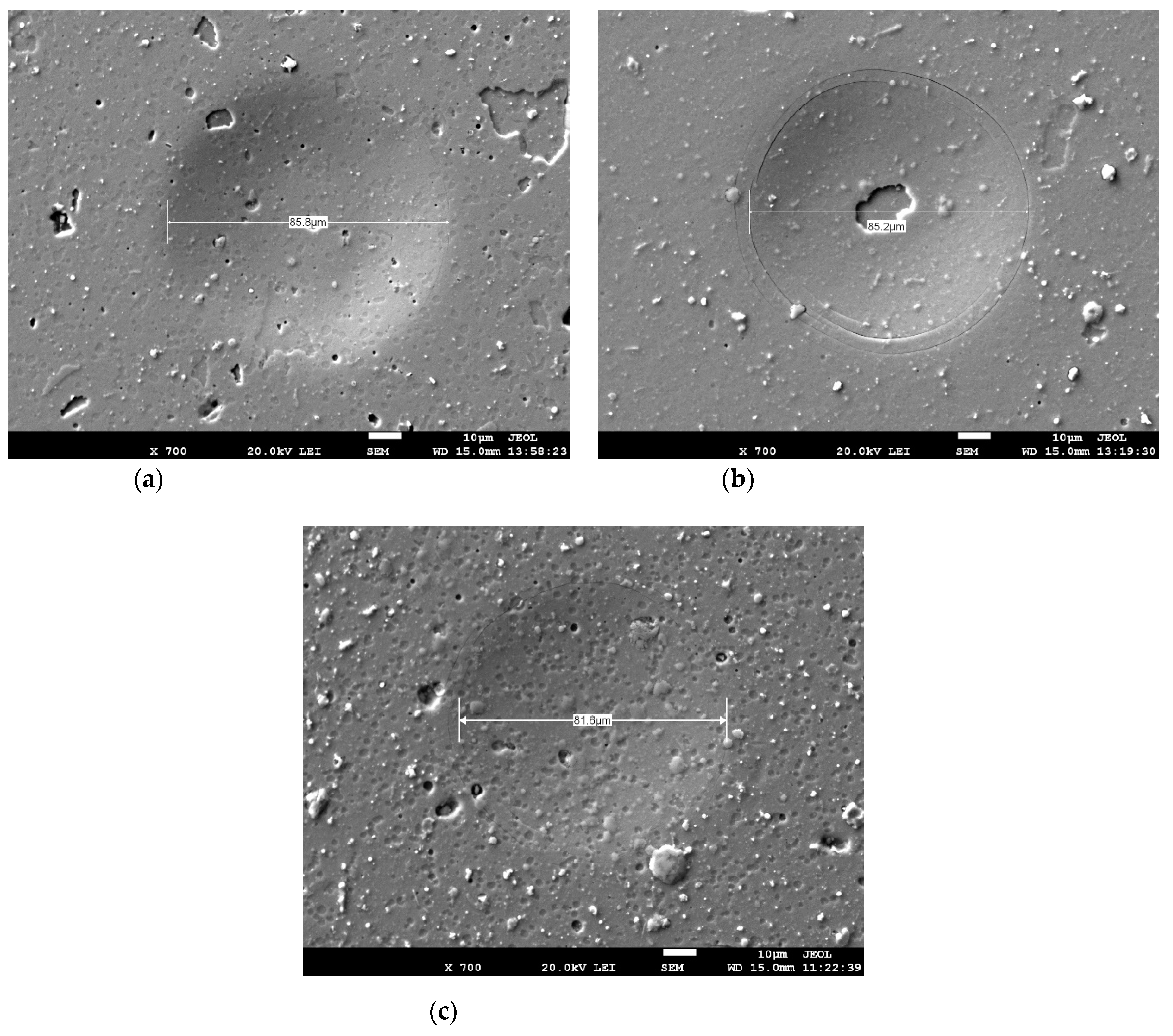
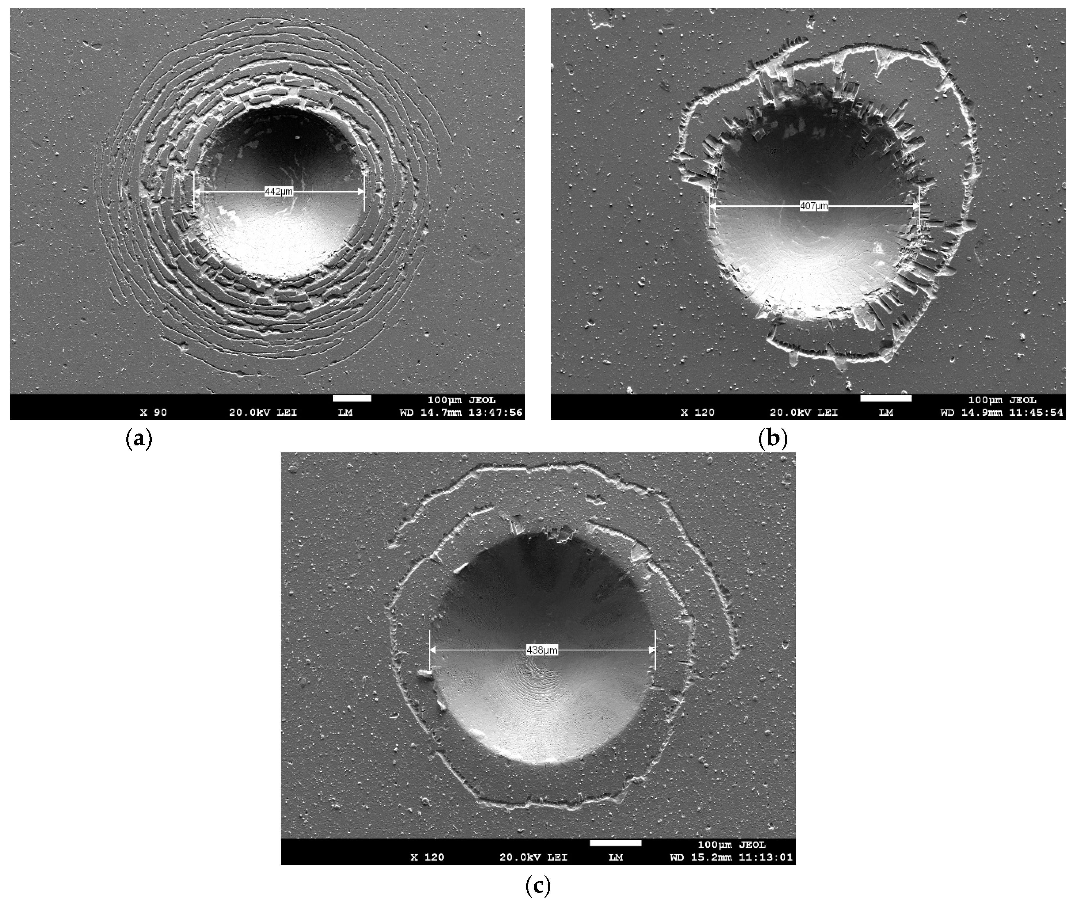
3.2.3. High-Resolution Analysis of Indentation Imprints

Figure 10 and Figure 11 depict micrographs of the indentation imprints taken with an electron microscope (HRSEM). Figure 10 shows micrographs of imprints after the test at a loading force of 50 N. The imprint on the surface of the nACo3 coating deposited on HSS substrate is shown in Figure 10a. Spalling areas can be seen at the edges of the imprint. In the case of the TiXCo3 coating (Figure 11a), a higher number of circumferential cracks are obvious. Less cracks can be observed around the imprint of the nACo3 coating deposited on HSS substrate, but spalling was documented. The nACo3 coating deposited on sintered carbide substrate is characterized by less cracks and insignificant spalling near the circumferential crack.
The results from the microscopic examination accord with the data captured using AE (Figure 9a,b). The TiXCo3 coating is characterized by the highest values of hits energy, which were caused by plastic deformation of the substrate at the periphery of the indentation imprint. The TiXCo3 coating, according to the material parameters calculated from nanoindentation data (Figure 6), had the highest plasticity index and deformation resistance. Therefore, it must also have the best tribological behavior out of all the specimens. This statement was confirmed mainly after using small loads where the influence of substrates is negligible. However, this coating was not the best solution in the case of high loads where plastic deformation of the substrate occurs. This behavior is explained by the high hardness and small elastic modulus of the coating. This conclusion can be confirmed based on results with the nACo3 coating deposited on the same substrate. As can be seen in Figure 9, the specimen with an nACo3 coating deposited on different substrates reached different values of hits energy. The nACo3 coating deposited on the SC reached a slightly lower value, which may have been caused by the hard substrate resistant to deformation.

4. Discussion

The mechanical and tribological behavior of two coatings were investigated by two different indentation methods. The nanoindentation method was used to determine the material properties of coatings. Then, supplemental parameters from the indentation data were calculated and their wear was estimated.
The second method was indentation of the same coatings systems, but with acoustic emission signals recorded, which enabled an investigation of crack formation and spalling of coatings at higher loading forces.
A comparison of results using both methods results was performed and evaluated.

4.1. Nanoindentation

According to the material parameters obtained from the nanoindentation tests, we obtained the following findings:
  • The TiXCo3 coating deposited on HSS has the highest hardness of all measured specimens at low indentation depths. However, as depths increase the hardness reduces. The elastic modulus curve followed a similar pattern.
  • The nACo3 coating deposited on both substrates had the same hardness at low depths. The hardness of both nACo3 coatings also increased with an increase of indentation depths. The opposite phenomenon was observed for the elastic modulus. The nACo3 coating deposited on SC had higher values over the whole range of depths.
  • All hardness changes of coatings due to an increase of indentation depths were probably caused by differences in the substrates.
  • The plasticity index and plastic deformation resistance reached the highest values for the TiXCo3 coating deposited on HSS.
  • The nACo3 coating showed different values of plasticity index and plastic deformation resistance parameters. nACo3 deposited on SC had the lowest values of both calculated parameters.
According to the measured and calculated parameters, we can assume that the most durable coating is TiXCo3. This coating is very hard and resistant to high loadings.
We also confirmed our findings that there is a difference in measured material parameters between both nACo3 coatings deposited on different substrates. nACo3 deposited on SC reached higher values of elastic modulus but also had the lowest values of plasticity index and plastic deformation resistance.

4.2. Macroindentation and AE Measuring

The acoustic emission signals captured during macroindentation tests at maximum loading forces of 50 and 1500 N were evaluated and confirmed by microscopic examination of indentation imprints. We made the following findings:
Low load tests Fmax = 50 N
  • The coating-substrate systems with the lowest number of cracks was nACo3 deposited on sintered carbide and TiXCo3 on HSS.
  • Hits energy parameters showed that the nACo3 coating deposited on high-speed steel is susceptible to spalling at low indentation loading force.
High load tests Fmax = 1500 N
  • From the number of hits parameter, we found that the most susceptible coatings to cracking are both the TiXCo3 and nACo3 coatings deposited on high speed steel.
  • Based on the hits energy parameter, we were able to determine that the TiXCo3 coating on HSS was more susceptible to a loss of adhesion and spalling of the coating at high loads, while nACo3 deposited on high-speed steel was less susceptible at high loads, but the least susceptible was nACo3 deposited on sintered carbide.
All of our findings were confirmed by micrographs of indentation imprints according to the VD3198 standard [30]. All coatings were acceptable but the TiXCo3 coating was characterized by the most serious failures. The best results during the high load indentation test were obtained with the nACo3 coating deposited on sintered carbide. This was confirmed with the curves shown in Figure 12. The number of hits of all measured specimens, captured during the tests at maximum loading force of 1500 N, exceeded all three thresholds adjusted accordingly based on Table 3. Less hits were captured during the test with the nACo3 coating deposited on sintered carbide and their occurrence started at higher loading forces compared to the other specimens. The wear resistance of the nACo3 coating was higher when deposited on sintered carbide substrate than HSS. This difference may have been caused by differences in the elasto-plastic properties between the substrates. However, the TiXCo3 coating deposited on HSS was similarly susceptible to cracking as nACo3 deposited on the same substrate.
We believe the hit parameter is related to crack formation and other material instabilities caused by high tensile stress in the plastic deformation zone around the imprint, and by high compression stress in the imprint area.
The hits energy parameter can be used for quantification of cracks size and spalling area of the coating layer.
Figure 13 shows the hits energy recorded during the tests at maximum loading force of 1500 N for every tested coating–substrate combination. It can be seen that less energy was released during the test of nACo3 coating deposited on sintered carbide, confirming our previous findings. Most energy was released during indentation for the combination of the TiXCo3 coating deposited on HSS.
Comparing the results in Figure 12 and Figure 13, it is possible to see how the coatings are susceptible to cracking and spalling. The nACo3 coating deposited on sintered carbide released least energy during indentation and therefore we can assume that it is the best solution for high loading applications based on its good elastic properties of the coating. The substrate is also highly resistant to plastic deformation.
Contrary to parameters calculated from nanoindentation tests, where only the coating was investigated, the most durable coating–substrate system at high loads was nACo3 deposited on sintered carbide (Figure 14).

5. Conclusions

In this study, samples with nACo3 and TiXCo3 coatings deposited on high-speed steel HS6-5-2-5 (1.3243) and sintered carbide substrates were investigated in terms of coating wear and adhesion properties using two different methods. Nanoindentation is the most popular method currently used to characterize a coating’s parameters. In this paper, we used the coating hardness and elastic modulus calculations developed by Oliver and Pharr [23,24] and used the results to calculate other parameters including the plasticity index, H/E, and deformation resistance, H3/E2. These parameters were used to evaluate the tribological and wear resistance of coatings by high loading test performance data.
The second indentation method used to determine wear resistance at high loads was the instrumented Daimler–Mercedes test, while acoustic emission was used to detect crack formation and spalling of coatings. A special measuring device have been developed for this purpose.
The coatings were deposited on different substrates, which resulted in different mechanical properties being obtained for the same coating. The results of nanoindentation were compared with the results of recorded AE data analysis captured during macroindentation tests. According to the acoustic emission analysis we conclude the following:
  • Comparing the acoustic emission events represented by the number of hits parameter, we conclude that for high loading applications the substrate has a major influence on the mechanical properties. We found around the same number of hits for different coatings deposited on HSS substrate and approximately the half number of hits for coatings deposited on sintered carbide. If the substrate is resistant to plastic deformation, then the coating is also more resistant to cracking and spalling.
We have demonstrated that the use of acoustic emission measuring technology is more appropriate when the adhesion and wear properties of coatings must be investigated. This method is easy to use and is significantly faster, as there is no need to make a large number of indentations. There is also no need to use precise measuring technology. We can see crack creations in real time and quickly evaluate a hard coating’s susceptibility to loss of adhesion when a large strain is applied.
The acoustic emission signal detection and evaluation makes it possible to evaluate:
  • The susceptibility of the coating to untimely cracking;
  • Spalling of coatings;
  • The loading force when spalling starts to occur.
The aim of this paper was to find a more effective and accurate method to determine overall tribological properties of hard coatings deposited on hard substrates. One of the most outstanding advantages of the acoustic emission method is its fast and precise detection of cracking and spalling in a coating. It is also possible to determine the critical forces when cracking and spalling occurs.

Author Contributions

Conceptualization, P.D., M.S. and Ľ.Č.; methodology, Ľ.Č.; software, D.M. and V.K.; validation, Ľ.Č., D.M. and V.K.; formal analysis, P.D. and V.K.; investigation, P.D.; resources, P.D. and D.M.; data curation, M.S.; writing—original draft preparation, P.D.; writing—review and editing, D.M., M.S. and S.I.Š.; visualization, P.D. and D.M.; supervision, Ľ.Č. and V.K.; project administration, L.Č.; funding acquisition, Ľ.Č. and V.K. All authors have read and agreed to the published version of the manuscript.

Funding

This research was supported by the Slovak Research and Development Agency under the contract No. APVV-15-0168, and the Slovak Republic Scientific Grant Agency (VEGA) within Grant No. 1/0540/19. This publication was supported by the Operational Programme Research and Innovation for the project: “Scientific and Research Centre of Excellence SlovakION for Material and Interdisciplinary Research” project ITMS2014+: 313011W085, co-financed by the European Regional Development Fund.

Institutional Review Board Statement

Not applicable.

Informed Consent Statement

Not applicable.

Data Availability Statement

Not applicable.

Acknowledgments

The authors would also like to thank the Walloon region for financial support in the frame of the INDMAT project (BEWARE FELLOWSHIPS), co-funded by the European Union (FP7—Marie Curie Actions).

Conflicts of Interest

The authors declare no conflict of interest.

References

  1. Baldan, A. Adhesion phenomena in bonded joints. Int. J. Adhes. Adhes. 2012, 38, 95–116. [Google Scholar] [CrossRef]
  2. Popov, V.L.; Pohrt, R.; Li, Q. Strength of adhesive contacts: Influence of contact geometry and material gradients. Friction 2017, 5, 308–325. [Google Scholar] [CrossRef]
  3. Duminica, F.D.; Belchi, R.; Libralesso, L.; Mercier, D. Investigation of Cr(N)/DLC multilayer coatings elaborated by PVD for high wear resistance and low friction applications. Surf. Coat. Technol. 2018, 337, 396–403. [Google Scholar] [CrossRef]
  4. Sousa, V.F.C.; Silva, F.J.G. Recent advances in turning processes using coated tools—A comprehensive review. Metals 2020, 10, 170. [Google Scholar] [CrossRef] [Green Version]
  5. Mercier, D.; Mandrillon, V.; Parry, G.; Verdier, M.; Estevez, R.; Bréchet, Y.; Maindron, T. Investigation of the fracture of very thin amorphous alumina film during spherical nanoindentation. Thin. Solid. Films 2017, 638, 34–47. [Google Scholar] [CrossRef]
  6. Krabbe, M. Crack Mechanisms and Crack Interaction in Thin Films; Department of Engineering, Technical report ME-TR-1; Aarhus University: Aarhus, Denmark, 2012; pp. 18–28, ISSN 2245-4594; Available online: https://tidsskrift.dk/me/article/view/21125/18625 (accessed on 17 May 2021).
  7. Fu, K.; Tang, Y.; Chang, L. Toughness Assessment and Fracture Mechanism of Brittle Thin Films Under Nano-Indentation, Fracture Mechanics—Properties, Patterns and Behaviours; IntechOpen: Rijeka, Italy, 2016; pp. 121–144. [Google Scholar] [CrossRef] [Green Version]
  8. Malzbender, J.; Den Toonder, J.M.J.; Balkenende, A.R.; De With, G. Measuring mechanical properties of coatings: A methodology applied to nano-particle-filled sol–gel coatings on glass. Mater. Sci. Eng. R Rep. 2002, 36, 47–103. [Google Scholar] [CrossRef]
  9. Azizpour, A.; Hahn, R.; Klimashin, F.F.; Wojcik, T.; Poursaeidi, E.; Mayrhofer, P.H. Deformation and cracking mechanism in CrN/TiN multilayer coatings. Coatings 2019, 9, 363. [Google Scholar] [CrossRef] [Green Version]
  10. Kramer, D.E.; Yoder, K.B.; Gerberich, W.W. Surface constrained plasticity: Oxide rupture and the yield point process. Philos. Mag. 2001, 81, 2033–2058. [Google Scholar] [CrossRef]
  11. Wang, M.G.; Ngan, A.H.W. Indentation strain burst phenomenon induced by grain boundaries in niobium. J. Mater. Res. 2004, 19, 2478–2486. [Google Scholar] [CrossRef] [Green Version]
  12. Mercier, D. PopIn Toolbox Documentation; GitHub. Available online: https://www.researchgate.net/publication/328530953_PopIn_Toolbox_documentation (accessed on 30 July 2021).
  13. International Organization for Standardization. ISO 14577-1, -2, -3, Metallic Materials–Instrumented Indentation Test for Hardness and Materials Parameters–Part 1: Test Method, Part 2: Verification and Calibration of Testing Machines, Part 3: Calibration of Reference Blocks; International Organization for Standardization: Geneve, Switzerland, 2002. [Google Scholar]
  14. International Organization for Standardization. ISO 14577-4, Metallic Materials–Instrumented Indentation Test for Hardness and Materials Parameters–Part 4: Test Method for Metallic and Non-Metallic Coatings; ISO–International Organization for Standardization: Geneve, Switzerland, 2007. [Google Scholar]
  15. Silva, F.J.G. Nanoindentation on tribological coatings. In Applied Nanoindentation in Advanced Materials; John Wiley and Sons, Ltd.: Hoboken, NJ, USA, 2017; pp. 111–133. ISBN 9781119084495. [Google Scholar]
  16. Vidakis, N.; Antoniadis, A.; Bilalis, N. The VDI 3198 indentation test evaluation of a reliable qualitative control for layered compounds. J. Mater. Process. Technol. 2003, 143, 481–485. [Google Scholar] [CrossRef]
  17. Haršáni, M.; Sahul, M.; Zacková, P.; Čaplovič, Ľ. Study of cathode current effect on the properties of CrAlSiN hard coatings deposited by LARC. Vacuum 2017, 139, 1–8. [Google Scholar] [CrossRef]
  18. Polcar, T.; Cavaleiro, A. High-temperature tribological properties of CrAlN, CrAlSiN and AlCrSiN coatings. Surf. Coat. Technol. 2011, 206, 1244–1251. [Google Scholar] [CrossRef]
  19. Ding, X.; Zeng, X.T.; Liu, Y.C. Structure and properties of CrAlSiN Nanocomposite coatings deposited by lateral rotating cathod arc. Thin. Solid. Films 2011, 519, 1894–1900. [Google Scholar] [CrossRef]
  20. Carvalhoa, S.; Ribeiroa, E.; Reboutaa, L.; Pacaudb, J.; Goudeaub, P.; Renaultb, P.O.; Rivièreb, J.P.; Tavares, C.J. PVD grown (Ti,Si,Al)N nanocomposite coatings and (Ti,Al)N/(Ti,Si)N multilayers: Structural and mechanical properties. Surf. Coat. Technol. 2003, 172, 109–116. [Google Scholar] [CrossRef]
  21. Mishra, S.K. Toughening of nanocomposite hard coatings. Rev. Adv. Mater. Sci. 2020, 59, 553–585. [Google Scholar] [CrossRef]
  22. Cselle, T.; Coddet, O.; Galamand, C.; Holubar, P.; Jilek, M.; Jilek, J.; Luemkemann, A.; Morstein, M. TripleCoatings–New generation of PVD-coatings for cutting tools. J. Mach. Manuf. 2009, 49, 19–25. [Google Scholar]
  23. Oliver, W.; Pharr, G. An improved technique for determining hardness and elastic modulus using load and displacement sensing indentation experiments. J. Mater. Res. 1992, 7, 1564–1583. [Google Scholar] [CrossRef]
  24. Oliver, W.; Pharr, G. Measurement of hardness and elastic modulus by instrumented indentation: Advances in understanding and refinements to methodology. J. Mater. Res. 2004, 19, 3–20. [Google Scholar] [CrossRef]
  25. Musil, J. Tribological and mechanical properties of nanocrystalline-TiC/a-C nanocrystalline-TiC/a-C nanocomposite thin films. J. Vac. Sci. Technol. 2010, 28, 244. [Google Scholar] [CrossRef]
  26. Musil, J. Hard and superhard nanocomposite coatings. Surf. Coat. Technol. 2000, 125, 322–330. [Google Scholar] [CrossRef]
  27. Musil, J. Hard nanocomposite coatings: Thermal stability, oxidation resistance and toughness. Surf. Coat. Technol. 2012, 207, 50. [Google Scholar] [CrossRef]
  28. Musil, J.; Kunc, F.; Zeman, H.; Poláková, H. Relations between hardness, youngs modulus and elastic recovery in hard nanocomposite coatings. Surf. Coat. Technol. 2002, 154, 304–313. [Google Scholar] [CrossRef]
  29. Leyland, A.; Matthews, A. On the significance of the H/E ratio in wear control: A nanocomposite coating approach to optimised tribological behaviour. Wear 2000, 246, 1–11. [Google Scholar] [CrossRef]
  30. Verein Deutscher Ingenieure Normen, VDI 3198; VDI-Verlag: Dusseldorf, Germany, 1991.
  31. Grosse, U.C.H.; Ohtsu, M. Acoustic Emission Testing, 1st ed.; Springer: Berlin/Heidelberg, Germany, 2008; pp. 41–51. ISBN 978-3-540-69895-1. [Google Scholar]
  32. Youyuan, L.; Zongjin, L. Study of the relationship between concrete fracture energy and AE signal energy under uniaxial compression. J. Mater. Civ. Eng. 2012, 24, 538–547. [Google Scholar] [CrossRef]
  33. Drobný, P. Acoustic emission analysis of hard coatings cracking during indentation test. IOP Conf. Ser. Mater. Sci. Eng. 2020, 726, 012004. [Google Scholar] [CrossRef]
Figure 1. Coating cracks after indentation: (a) Circumferential cracks; (b) channel cracks and radial cracks.
Coatings 11 00919 g001
Figure 2. VDI 3198 indentation test.
Coatings 11 00919 g002
Figure 3. Cross-section of nACo3 surface.
Coatings 11 00919 g003
Figure 4. Specimen indentation with special AE sensor DAKEL type Holder.
Coatings 11 00919 g004
Figure 5. Load-displacement curves of all samples.
Coatings 11 00919 g005
Figure 6. Calculated mechanical properties of experimental samples: (a) hardness H; (b) elastic modulus E.
Coatings 11 00919 g006
Figure 7. Calculated mechanical properties of experimental samples: (a) Plasticity index H/E, (b) plastic deformation resistance H 3 / E 2 .
Coatings 11 00919 g007
Figure 8. Number of hits (originally exported from Daemon system): (a) Fmax = 50 N; (b) Fmax = 1500 N.
Coatings 11 00919 g008
Figure 9. Hits Energy curves for TiXCo3/HSS, nACo3/HSS, and nACo3/SC captured at the maximal force of (a) 50 N and (b) 1500 N.
Coatings 11 00919 g009
Figure 10. Indentation imprints at Fmax = 50 N: (a) TiXCo3/HSS, (b) nACo3/HSS, and (c) nACo3/SC.
Coatings 11 00919 g010
Figure 11. Indentation imprints at Fmax = 1500 N: (a) TiXCo3/HSS, (b) nACo3/HSS, and (c) nACo3/SC.
Coatings 11 00919 g011
Figure 12. Cumulative number of hits.
Coatings 11 00919 g012
Figure 13. Maximum hits energy reached at Fmax = 1500 N.
Coatings 11 00919 g013
Figure 14. Graphic radar representation of acoustic emission parameter results in comparison with values from nanoindentation.
Coatings 11 00919 g014
Table 1. Nanoindentation test parameters.
Strain Rate (N/s)MatrixMaximum Indentation Depth (µm)
0.056 × 6 indents spaced by 50 µm2
Table 2. Parameters of the indentation test ( F max = 1500   N ) .
Maximum Force (N)Holding Force (N)Dwell Time (s)Speed of Indenter (mm/min)
1500500100.2
Table 3. AE detection thresholds.
Maximum Force (N)Threshold (dB)Amplification (dB)
502096
15002066
Publisher’s Note: MDPI stays neutral with regard to jurisdictional claims in published maps and institutional affiliations.

