Article

Unconditionally Stable System Incorporated Factorization-Splitting Algorithm for Blackout Re-Entry Vehicle

1
School of Automation Engineering, University of Electronic Science and Technology of China, Chengdu 611731, China
2
Beijing Institute of Aerospace Systems Engineering, Beijing 100076, China
*
Author to whom correspondence should be addressed.
Electronics 2023, 12(13), 2892; https://doi.org/10.3390/electronics12132892
Submission received: 27 May 2023 / Revised: 23 June 2023 / Accepted: 27 June 2023 / Published: 30 June 2023
(This article belongs to the Special Issue Advances in Electromagnetic Interference and Protection)

Abstract

:
A high-temperature plasma sheath is generated on the surface of the re-entry vehicle through the conversion of kinetic energy to thermal and chemical energy across a strong shock wave at the hypersonic speed. Such a condition results in the forming of a blackout which significantly affects the communication components. To analyze the re-entry vehicle at the hypersonic speed, an unconditionally stable system incorporated factorization-splitting (SIFS) algorithm is proposed in finite-difference time-domain (FDTD) grids. The proposed algorithm shows advantages in the entire performance by simplifying the update implementation in multi-scale problems. The plasma sheath is analyzed based on the modified auxiliary difference equation (ADE) method according to the integer time step scheme in the unconditionally stable algorithm. Higher order perfectly matched layer (PML) formulation is modified to simulate open region problems. Numerical examples are carried out to demonstrate the performance of the algorithm from the aspects of target characteristics and antenna model. From resultants, it can be concluded that the proposed algorithm shows considerable accuracy, efficiency, and absorption during the simulation. Meanwhile, plasma sheath significantly affects the communication and detection of the re-entry vehicle.

1. Introduction

A plasma sheath is formed on the surface of the re-entry vehicle due to the conversion of kinetic energy to thermal and chemical energy across a strong shock wave at the hypersonic speed [1]. The occurrence of the blackout phenomenon significantly affects the detection and communication of the re-entry vehicle [2,3]. The accurate simulation of plasma sheaths has become a frontier science during the investigation of blackout phenomena. Several methods have been developed including the physics optic method, shooting bouncing ray method, and so on. However, most of them focus on the rapid calculation of electrically large objects [4,5,6,7,8]. To analyze the time variation behavior, the finite-difference time-domain (FDTD) algorithm shows potential in the simulation of the blackout phenomenon [9]. The conventional FDTD algorithm shows limitations in a multi-scale problem that is composed of antenna and vehicle models. By applying the conventional algorithm to the multi-scale problem directly, the mesh size must be chosen as fine enough to ensure the Courant–Friedrichs–Levy (CFL) condition [10]. Such a condition results in an extremely large computational domain and extensively long simulation duration. To overcome the CFL condition and improve the calculation efficiency, unconditionally stable algorithms are proposed [11,12,13,14]. Most of the unconditionally stable algorithms are the sub-step procedure. The sub-step procedure solves the single iteration with several sub-equations. The numerical dispersion increases with the increment of sub-step equations [15]. Meanwhile, memory consumption also increases in the sub-step procedure [16]. Such a condition leads to a decrement in efficiency and accuracy. To overcome such conditions, one-step schemes are introduced including leapfrog scheme, fundamental scheme, and so on [17,18]. However, there are still limitations in the arithmetical manipulations [19,20]. The one-step Crank-Nicolson (CN) scheme can update Maxwell’s equations within a single iteration which is merely efficient in one-dimensions. By applying the CN scheme to multi-dimension problems, a large sparse matrix must be calculated at each time step which results in a more expensive calculation. To alleviate such conditions, approximate CN schemes are introduced which include approximate decoupling and Douglas-Gunn schemes [21,22]. However, two-dimensional algorithms cannot be directly employed in three-dimensional problems [23]. Thus, approximate-factorization-splitting (AFS) and directly-splitting (DS) schemes are introduced into three-dimensional problems [24,25]. However, massive components, auxiliary variables, and coefficients must be calculated at each time step. In order to alleviate such conditions, a system incorporated directly-splitting (SIDS) algorithm is introduced based on the digital signal processing (DSP) technique [26]. According to the system-incorporated scheme, the entire algorithm can be regarded as the implementation of a signal processing technique. Thus, the algorithm can be simplified by avoiding the calculation of repeated coefficients, field components, and auxiliary variables. However, it has been testified that the DS algorithm shows accuracy degeneration due to the direct approximation of field components [27,28].
A plasma sheath is formed on the surface of the re-entry vehicle at the hypersonic speed. For the investigation of micro-behavior, plasma sheaths can be expressed by the anisotropic magnetized plasma [29]. Several techniques are carried out which are mainly based on the conventional explicit FDTD algorithm [30,31]. Most of them hold field components at a half-integer time step. By applying them directly to the one-step unconditionally stable algorithms, the algorithm will become inaccurate or unstable. To alleviate such conditions, algorithms are modified at the integer time step. Among the existing algorithms, the auxiliary difference equation (ADE) method shows considerable efficiency and accuracy [32,33].
For the open region problems, adequate absorbing boundary conditions must be introduced to efficiently simulate the unbounded grids. The perfectly matched layer (PML) is regarded as one of the most powerful absorbing boundary conditions [34]. The original PML formulation is based on the split-field scheme with four auxiliary variables which results in the decrement of absorption and efficiency. In order to alleviate such conditions, unsplit-field schemes are introduced including stretched coordinate (SC), complex-frequency-shifted (CFS), and convolutional PML (CPML) schemes [35,36,37]. Compared with the SC-PML scheme, CFS-PML formulation shows advantages in late-time reflections and low-frequency evanescent waves. However, both cannot efficiently absorb low-frequency propagation waves. A higher-order scheme is proposed which is implemented by multiplying the stretched coordinate variables together into a single term [38]. The original higher-order PML formulation is the split-field scheme which holds six auxiliary variables. The modified higher-order schemes are carried out with four auxiliary variables to improve the entire performance [38,39,40]. Recently, an unconditionally stable higher-order CPML scheme is proposed to further simplify the implementation [40,41].
It can be concluded that several limitations still should be addressed in the simulation of blackout re-entry vehicles. The problems mainly include the solution of multi-scale problems, calculation of magnetized plasma, and absorbing boundary conditions for complex media.
Here, an unconditionally stable system incorporated factorization-splitting (SIFS) algorithm is proposed based on the DSP technique to efficiently simulate the multi-scale problem of the blackout re-entry vehicle. The plasma sheath can be expressed by the anisotropic magnetized plasma and solved by the modified ADE method. Higher order CPML formulation is proposed for the complex anisotropic media. Numerical examples including the antenna performance and target characteristics are carried out to illustrate the entire behavior of the algorithm. The results indicates that the proposed algorithm shows considerable accuracy, efficiency, and absorption. The employment of the SI method can simplify the implementation by avoiding the calculation of repeated coefficients, field components, and auxiliary variables. The existence of a plasma sheath significantly affects the communication and detection of the re-entry vehicle.

2. Formulation

Inside the anisotropic magnetized plasma regions, Maxwell’s equations in the higher-order PML regions can be written as [42]
j ω D = s × H
j ω μ 0 H = s × E
where D = ε 0 ε r E = E + J . The polarization current density of the anisotropic plasma can be expressed as
j ω J = ε 0 ω p 2 E ν J + ω b J
where ν , ω p and ω b are the damping constant, plasma frequency, and electron gyro-frequency, respectively [43]. The operator s can be expressed as
s = x ^ 1 S x x + y ^ 1 S y y + z ^ 1 S z z
where S η   ( η = x , y , z ) is the stretched coordinate variables of the higher order formulation with CFS factor, defined as
S η = ( κ η 1 + σ η 1 α η 1 + j ω ε 0 ) ( κ η 2 + σ η 2 α η 2 + j ω ε 0 )
where κ η n 1 ,   n = 1 , 2 is employed, σ η n and α η n are assumed to be positive real [44]. Maxwell’s equations can be divided into six individual components which almost hold the same forms [42]. Thus, the x-projection of electric components is employed as an example for demonstration. The other components can be obtained according to a similar approach. It can be observed that the algorithm can be solved from the aspects of plasma analyzation and unconditionally stable scheme implementation.

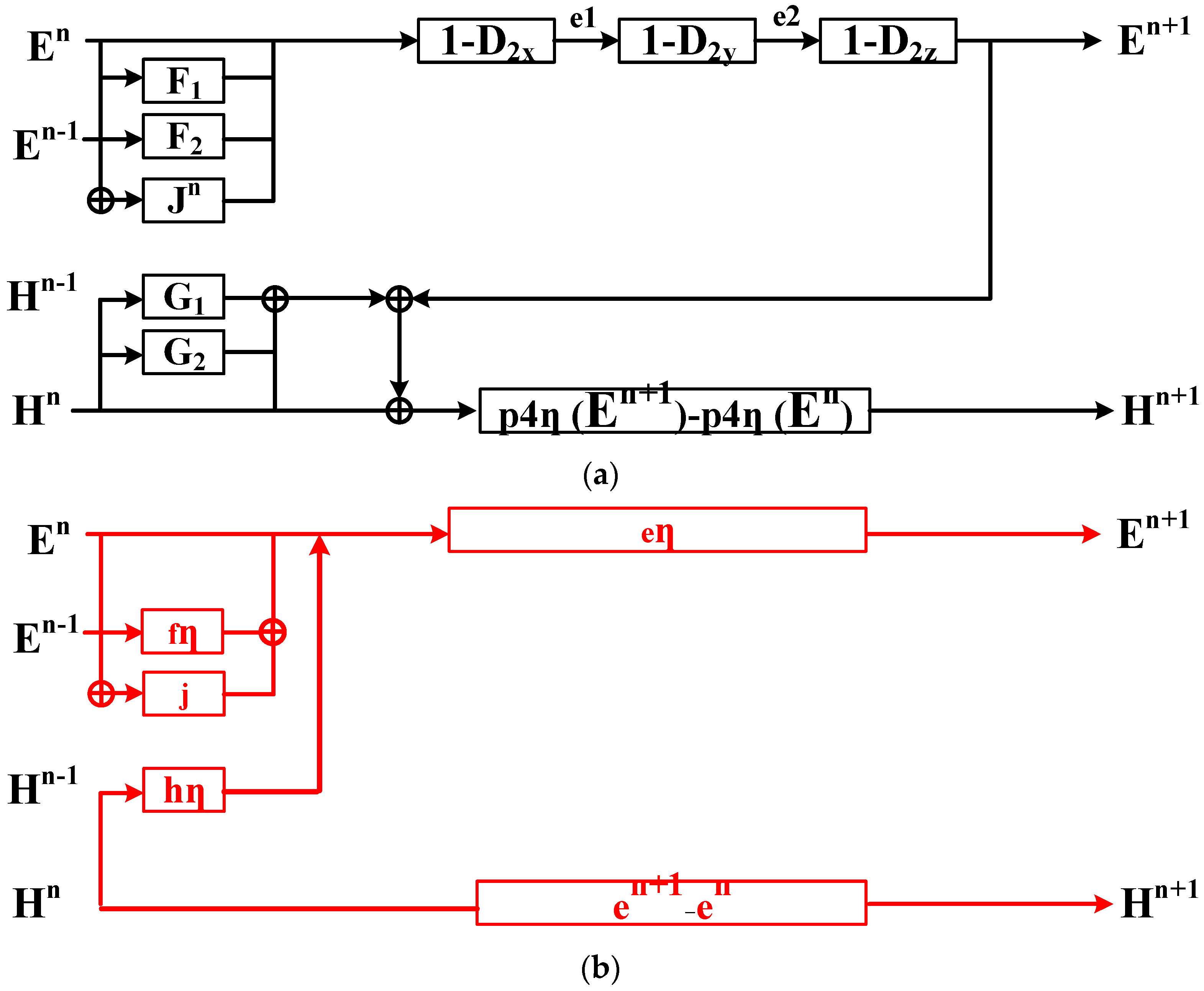
2.1. Modified ADE Algorithm for Unconditionally Stable SI Scheme

Supposing that the plasma is magnetized along the z-direction, the polarization current density can be expressed as
j ω J x + ν J x = ε 0 ω p 2 E x ω b J y
j ω J y + ν J y = ε 0 ω p 2 E y + ω b J x
j ω J z = ε 0 ω p 2 E z
According to the ADE method [45], components are discretized at the integer time step which can be given as
J x n + 1 J x n Δ t + ν ( J x n + 1 + J x n ) 2 = ε 0 ω p 2 ( E x n + 1 + E x n ) 2 ω b ( J y n + 1 + J y n ) 2
J y n + 1 J y n Δ t + ν ( J y n + 1 + J y n ) 2 = ε 0 ω p 2 ( E y n + 1 + E y n ) 2 + ω b ( J x n + 1 + J x n ) 2
J z n + 1 J z n Δ t = ε 0 ω p 2 ( E z n + 1 + E z n ) 2
It can be observed that the components are coupled which cannot be updated directly. To implement the algorithm, field components must be decoupled. By substituting Equation (9) into Equation (10) and Equation (10) into Equation (11), results can be given as
J x n + 1 = p 1 a J x n p 2 a J y n + p 3 a E x n + 1 + p 3 a E x n p 4 a E y n + 1 p 4 a E y n
J y n + 1 = p 1 a J y n + p 2 a J x n + p 3 a E y n + 1 + p 3 a E y n + p 4 a E x n + 1 + p 4 a E x n
J z n + 1 = J z n + p 5 a E z n + 1 + p 5 a E z n
where
p 1 a = [ 1 ( ν Δ t / 4 ) 2 ( ω b Δ t / 4 ) 2 ] / p 6 a ,   p 2 a = ω b Δ t / p 6 a ,   p 3 a = [ ε 0 Δ t ω p 2 ( 1 + ν Δ t / 4 ) ] / p 6 a ,
p 4 a = ( ε 0 Δ t 2 ω p 2 ω b ) / ( 2 p 6 a ) ,   p 5 a = [ ( 1 + ν Δ t / 4 ) 2 + ( ω b Δ t / 4 ) 2 ] / 2   and   p 6 a = ε 0 ω p 2 Δ t / 4 .
Through the employment of Equations (12)–(14), the plasma sheath can be analyzed. Meanwhile, it can be observed that the components at the time step of n + 1 still exists in these equations which leads to the decoupling of components in an unconditionally stable algorithm. Thus, they should be further decoupled during the implementation of the SIFS algorithm.

2.2. consumption, simulation duration, and time CPML Formulation

With the employment of higher-order CPML formulation, Maxwell’s equations can be given as [46]
D x t = 1 S y H z y 1 S z H y z
Equation (15) can be reorganized in the time domain by employing the inverse Fourier transform (IFT) method, given as
D x t = S ¯ y * H z y S ¯ z * H y z
where * represents the convolution operation. The stretched coordinate variable S ¯ η can be written as
S ¯ η ( t ) = ( α η 1 ( t ) + δ ( t ) κ η 1 ) ( α η 2 ( t ) + δ ( t ) κ η 2 )
where δ ( t ) represents the impulse function in the signal processing technique. α η ( t ) can be expressed as
α η n ( t ) = β η n e γ η n t u ( t )
where the coefficients can be given as
β η n = σ η n κ η n 2 ε 0 ,   γ η n = α η n ε 0 + σ η n κ η n ε 0 .
u ( t ) represents the unit function in the signal processing technique. By substituting Equation (18) into Equation (16) and employing the relationship of polarization current density, results can be given as
ε 0 E x t ε 0 J x t = α y 1 ( t ) α y 2 ( t ) * H z y α z 1 ( t ) α z 2 ( t ) * H y z 1 κ z 1 κ z 2 H y z 1 κ z 1 α z 2 ( t ) * H y z 1 κ z 2 α z 1 ( t ) * H y z + 1 κ y 1 κ y 2 H z y + 1 κ y 1 α y 2 ( t ) * H z y + 1 κ y 2 α y 1 ( t ) * H z y
According to the FDTD discretized form and recursive convolution method, results can be rewritten as
E x n + 1 = E x n + Δ t ε 0 ( δ y ( H z n ) κ y 1 κ y 2 δ z ( H y n ) κ z 1 κ z 2 + F x y 1 n κ y 2 + F x y 2 n κ y 1 F x z 1 n κ z 2 F x z 2 n κ z 1 + χ y 1 χ y 2 e ( γ y 1 + γ y 2 ) Δ t δ y ( H z n + 1 + H z n ) χ z 1 χ z 2 e ( γ y 1 + γ y 2 ) Δ t δ z ( H y n + 1 + H y n ) + J x n + 1 J x n )
where δ η represents the first-order discretized form in space
δ η { H y } = H y | η + 1 / 2 n + 1 / 2 H y | η 1 / 2 n + 1 / 2 Δ η
where χ η n = σ η n σ η n κ η n + α η n κ η n 2 ( e γ η n Δ t 1 ) e γ η n m Δ t . By introducing the coefficients, results can be given as
E x n + 1 = E x n + p 1 e y F x y 2 n + p 2 e y F x y 1 n p 1 e z F x z 2 n p 2 e z F x z 1 n + p 3 e y δ y ( H z n ) p 3 e z δ z ( H y n ) + p 4 e y δ y ( H z n + 1 + H z n ) p 4 e z δ z ( H y n + 1 + H y n ) + J x n + 1 J x n )
where the coefficients can be given as p 1 e η = Δ t / ε 0 κ η 1 , p 2 e η = Δ t / ε 0 κ η 2 , p 3 η = Δ t / ( ε 0 κ η 1 κ η 2 ) , and p 4 e η = ( χ η 1 χ η 2 e ( γ η 1 + γ η 2 ) Δ t ) / 2 ε 0 . Magnetic components can be obtained according to a similar procedure. It can be observed from Equation (22) that the components at the time step of n + 1 exists on both sides of the equations, including the magnetic components and polarization current density. In order to alleviate such condition, components at the time step n + 1 are substituted into Equation (22) as
E x n + 1 = E x n + p 1 y F x y 2 n + p 2 y F x y 1 n p 1 z F x z 2 n p 2 z F x z 1 n + p 3 y δ y ( H z n ) p 3 z δ z ( H y n ) ( 1 D 2 y D 2 z ) E x n + 1 = ( 1 + D 2 y + D 2 z ) E x n + p 1 e y F x y 2 n + p 2 e y F x y 1 n p 1 e z F x z 2 n p 2 e z F x z 1 n + p 3 e y δ y ( H z n ) p 3 e z δ z ( H y n ) + 2 p 4 e y p 4 h x δ y δ x E y n 2 p 4 e z p 4 h y δ z δ x E z n + 2 p 4 e y δ 2 y H z n 2 p 4 e z δ z H y n p 1 h x p 4 e z δ z G y x 2 n p 2 h x p 4 e z δ z G y x 1 n + p 1 h z p 4 e z δ z G y z 2 n + p 2 h z p 4 e z δ z G y z 1 n + p 1 h y p 4 e y δ y G z y 2 n + p 2 h y p 4 e y δ y G z y 1 n p 1 h x p 4 e y δ y G z x 2 n p 2 h x p 4 e y δ y G z x 1 n p 3 h x p 4 e z δ z δ x ( E z n ) + p 3 h z p 4 e z δ z δ z ( E z n ) + p 3 h y p 4 e y δ y δ y ( E x n ) p 3 h x p 4 e y δ y δ x ( E y n )          + ( p 1 a 1 ) J x n p 2 a J y n + 2 p 3 a E x n 2 p 4 a E y n
where the operator can be defined as D 2 η = p 4 η 2 δ η . By applying Equation (23) directly as an algorithm, large sparse matrices are formed at both sides of the equations which makes the computation much more expensive. To overcome such conditions, disturbance terms are added at both sides of Equation (23), ( D 2 x + D 2 x D 2 z + D 2 x D 2 y + D 2 y D 2 z D 2 x D 2 y D 2 z ) E x n + 1 and ( D 2 x + D 2 x D 2 z + D 2 x D 2 y + D 2 y D 2 z D 2 x D 2 y D 2 z ) E x n . The results can be re-organized as
( 1 D 2 x ) ( 1 D 2 y ) ( 1 D 2 z ) E x n + 1 = ( 1 + D 2 x + D 2 y D 2 z ) E x n + A n
where A n represents the other components at the time step of n. Although equation (24) can be solved according to the CNAFS algorithm in [25]. A large number of auxiliary variables, field components, and coefficients must be solved at each time step which results in the increment of memory consumption and simulation duration. To alleviate such conditions, the SI method is introduced in the z-domain based on the DSP technique. Such an operation avoids the calculation of repeated variables and multi-equation solutions. At the first step of the SI method, auxiliary variables are introduced as
f x n = p 1 e y F x y 2 n + p 2 e y F x y 1 n p 1 e z F x z 2 n p 2 e z F x z 1 n + p 3 e y δ y ( H z n ) p 3 e z δ z ( H y n ) g x n = p 1 h y p 4 e y δ y G z y 2 n + p 2 h y p 4 e y δ y G z y 1 n p 1 h x p 4 e y δ y G z x 2 n p 2 h x p 4 e y δ y G z x 1 n
p 1 h x p 4 e z δ z G y x 2 n p 2 h x p 4 e z δ z G y x 1 n + p 1 h z p 4 e z δ z G y z 2 n + p 2 h z p 4 e z δ z G y z 1 n
e η = p 3 η 1 δ y E η , e η 1 = E η 1 E η n ,   e η 2 = E η 2 E η n , e η n + 1 = E η n + 1 E η n
h z n = 2 p 4 e y δ 2 y H z n   and   h y n = 2 p 4 e z δ z H y n
j x n = ( p 1 a 1 ) J x n p 2 a J y n + 2 p 3 a E x n 2 p 4 a E y n
By employing auxiliary variables and field components, the original equation can be given as
( 1 D 2 y D 2 z ) E x n + 1 = ( 1 + D 2 y + D 2 z ) E x n + f x n + g x n + j x n + h z n h y n
In such circumstances, the FS scheme is employed to further solve the equation, given as
( 1 D 2 x ) e x 1 = E x n + f x n + g x n + j x n + h z n h y n
( 1 D 2 y ) e x 2 = e x 1
( 1 D 2 z ) e x n + 1 = e x 2
As can be observed that tri-diagonal matrices are formed on the left side of Equations (31)–(33). The matrices can be solved by the Thomas algorithm implicitly [47]. Through Equations (31)–(33), the entire algorithm can be given according to the Fourier method as a matrix whose features are smaller than 1 which ensures unconditional stability [48]. Meanwhile, the algorithm cannot only be implemented but also simplified according to the SIFS algorithm. The update procedure of the entire algorithm is shown in Figure 1. The blank and red colors represent the original CNAFS algorithm and SIFS algorithm, respectively.
It can be concluded that all of the components in the proposed SIFS algorithm can be solved individually which results in avoiding the calculation of repeated field components, auxiliary variables, and coefficients. Meanwhile, by employing proper auxiliary variables, the algorithm can be further simplified compared with the original CNAFS algorithm which also decreases the memory consumption and simulation duration.

3. Numerical Results and Discussion

Numerical examples are carried out to further demonstrate the effectiveness of the algorithm. The occurrence of blackout phenomenon results in significant influence on the target characteristic and antenna radiation which leads to the detecting failure and communication interruption.

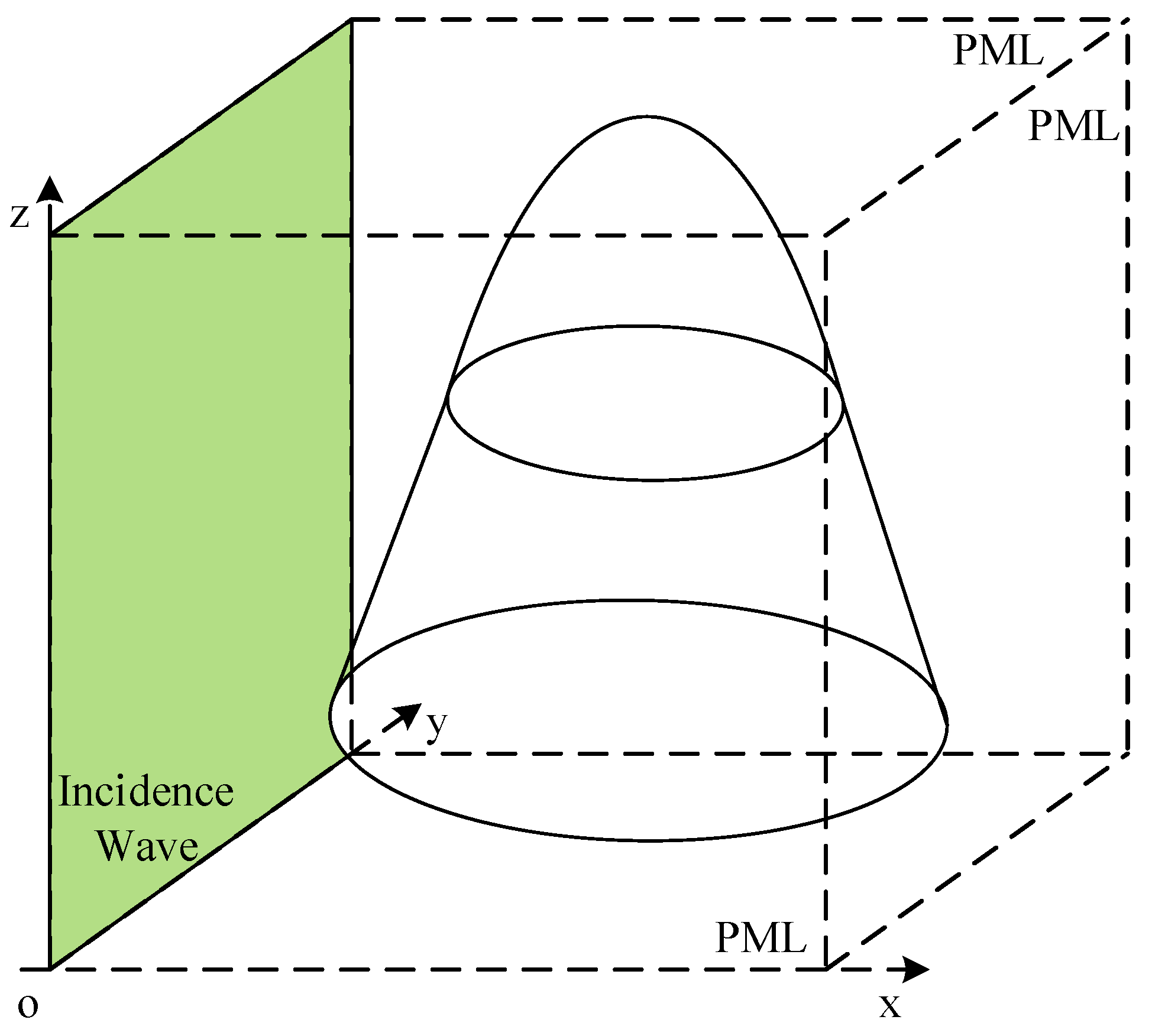
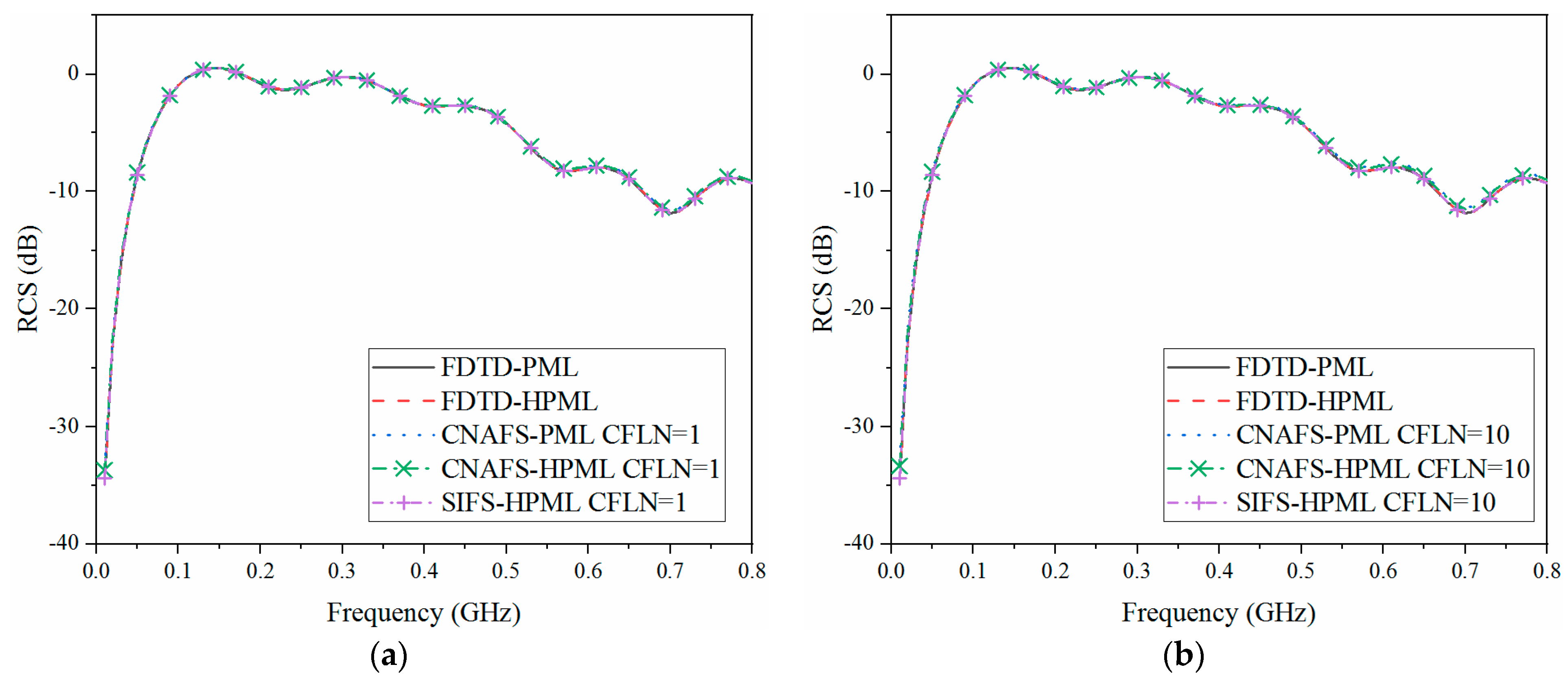
3.1. Target Characteristic Problem: Radar Echo Wave of the Blackout Re-Entry Vehicle

The existence of the plasma sheath shows a significant influence on the radar echo wave resulting in the variation of the target characteristic. Figure 2 shows the sketch picture of the re-entry vehicle model and the location of the antenna. The entire model can be regarded as a combination of half-sphere and half-pyramid. The radius of the sphere and upper radius of the half-pyramid hold the same dimensions as 0.2 mm. The bottom radius of the half-pyramid and the height are both 0.8 mm.
The plasma sheath can be expressed by the anisotropic plasma. The parameters of the plasma sheath can be simulated by the RAM-C based on the Computational Fluid Dynamics method as [49]. According to the same approach, the parameters under the condition of 80 km height in the atmosphere with a speed of 25 Ma. The temperature and the pressure of the atmosphere are 247.0 K and 30.0 Pa. A high temperature of 1700 K is formed due to the conversion of kinetic energy to thermal and chemical energy across a strong shock wave at the hypersonic speed. The plasma sheath is with the parameters and thickness of ω p = 2 π × 28.7 GHz, ω b = 1 × 10 11 GHz, ν = 20 GHz, and 0.1 m. On the surface of the re-entry vehicle, the monopole antenna is located along the normal vertical direction. The vehicle is made up of metal which can be expressed by the perfect electronic conductor (PEC) during the simulation.
Figure 3 shows the sketch picture of the re-entry vehicle computational domain. As is demonstrated that the vehicle model is located in the middle of the computational domain. The entire structure is a cube with a length of 1.5 m. The Gaussian pulse plane wave with the maximum frequency of 0.8 GHz incidents from the left of the structure. The rest part of the computational domain is filled with a vacuum. At the boundaries of the domain, they are terminated by 10-cell-PML regions to absorb the outgoing waves and reduce the wave reflections. The parameters inside the PML regions are chosen to obtain the best performance both in time and frequency domains. For comparison, the explicit CFS-PML in [50] and higher order formulation in [51], the original CNAFS algorithm with CFS-PML in [52], and the higher order formulation in [49] are chosen as examples.
According to the unconditionally stable algorithm, mesh size can be chosen to satisfy the demand of calculation rather than the limitation of the CFL condition. In order to satisfy the calculation accuracy, mesh sizes must be chosen as fine enough to conformal to the curves. Thus, the optimal mesh size which shows a compromise between accuracy and efficiency is chosen as Δ x = Δ y = Δ z = Δ = 3 mm. According to such circumstances, the entire computational domain can be discretized as 500 Δ x × 500 Δ y × 500 Δ z in FDTD grids. The maximum time step obtained by the CFL condition in the explicit algorithms can be chosen as Δ t max F D T D = 5 . 78 ps. CFL number (CFLN) which represents the enlargement of the time step can be obtained as C F L N = Δ t / Δ t max F D T D , where Δ t is the time step employed in the unconditionally stable algorithms. The target characteristic can be reflected by the radar cross-section (RCS) [53]. The RCS with the variation of the frequency obtained by different algorithms and CFLNs is shown in Figure 4. Meanwhile, the RCS parameter of the re-entry vehicle without the plasma sheath can be obtained by changing the plasma sheath to vacuum which is shown in Figure 5.
As can be concluded from Figure 4a and Figure 5a that the curves are almost overlapped with CFLN = 1. Such a condition indicates that the algorithms hold the same calculation accuracy with a small time step. In addition, such a condition also indicates that the calculation of anisotropic magnetized plasma is efficient. From Figure 4b and Figure 5b, curves show some shifting compared with the explicit FDTD-PML and FDTD-HPML schemes. Such a condition is caused by the enlargement of numerical dispersion with the enlargement of the time step. However, the calculation accuracy still shows a considerable level. As can be compared and observed between Figure 4 and Figure 5, the existence of the plasma sheath significantly affects the target characteristic. Nowadays, the communication system between the vehicle and the ground depends on the VHF and UHF band. The variation of scattering waves shows an influence on the detection. The effectiveness of the algorithm can be reflected by the memory consumption, simulation duration, and time reduction obtained by different algorithms and CFLN, as shown in Table 1.
As shown in Table 1, the explicit FDTD-PML scheme shows the least memory consumption and simulation duration due to the non-calculation of matrices with the explicit calculation procedure. The implicit schemes calculate nine matrices during each iteration which results in such a condition. In order to improve the efficiency, the time step can be enlarged according to the unconditionally stable algorithm which can also decrease the total iteration steps. Compared with the original scheme, the proposed algorithm shows improvement in efficiency due to the non-calculation of repeated auxiliary variables, coefficients, and field components according to the SI method. Meanwhile, the memory consumption and simulation duration of the higher order formulation also shows significant improvement due to the multiplying of stretched coordinate variables. The proposed algorithm still shows considerable behavior compared with the original scheme.

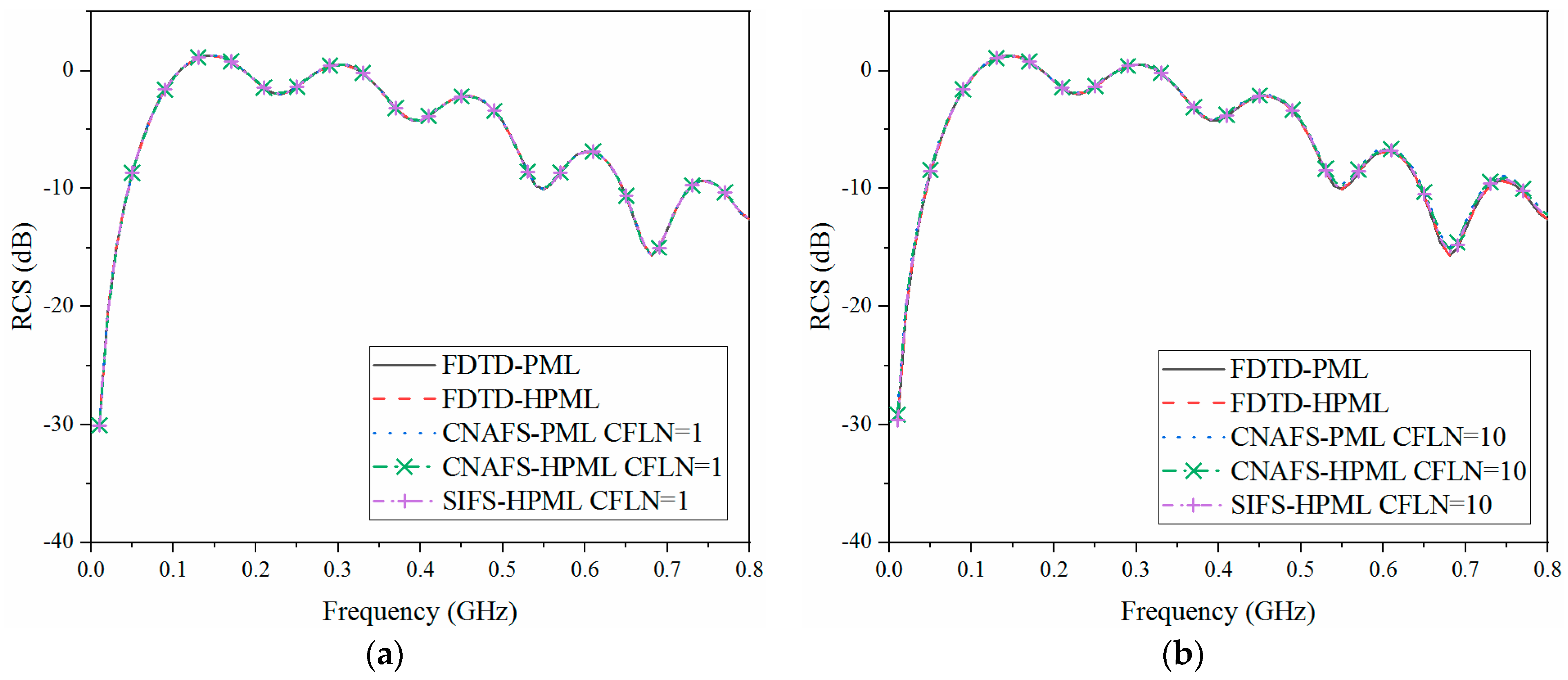
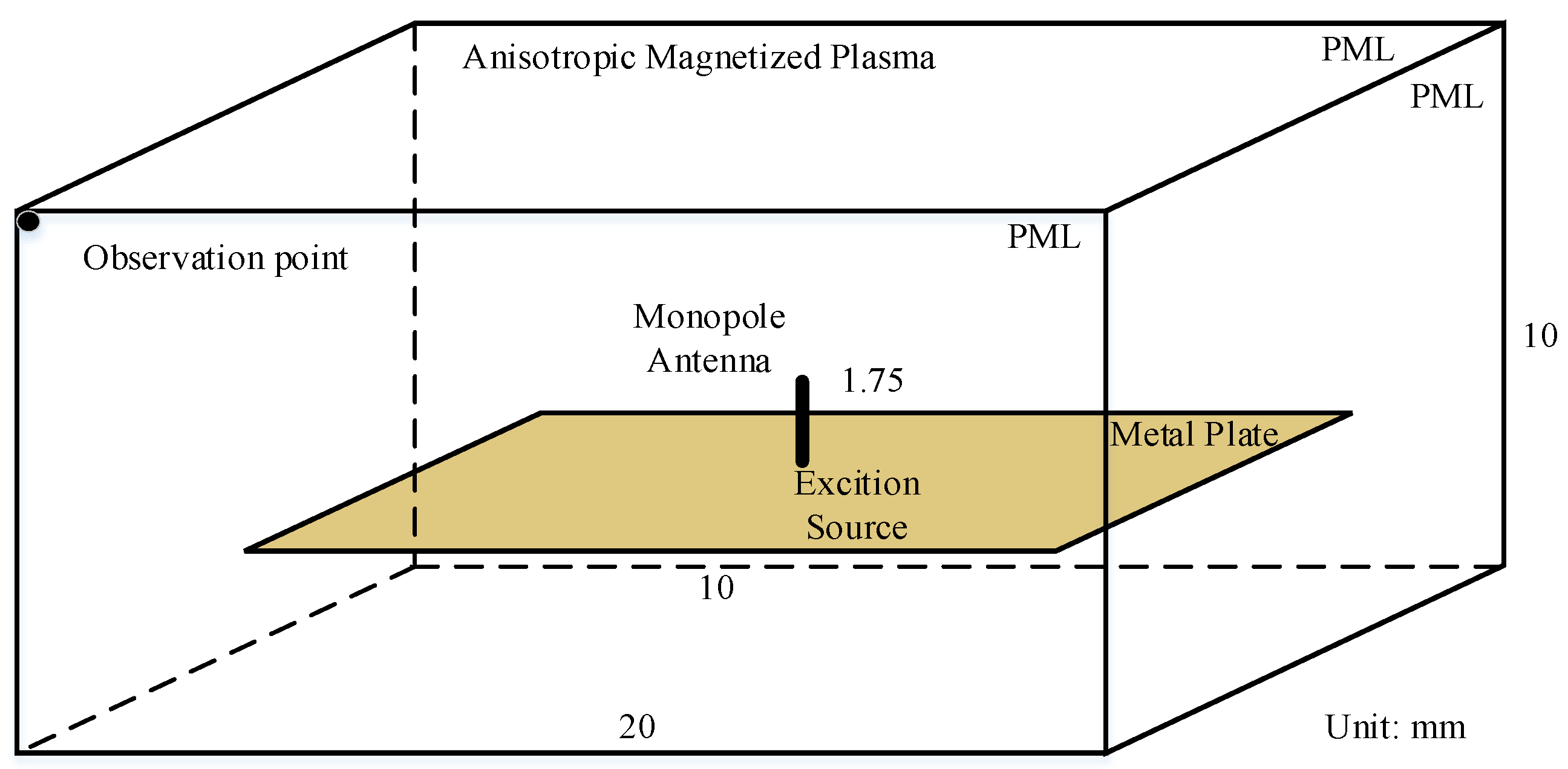
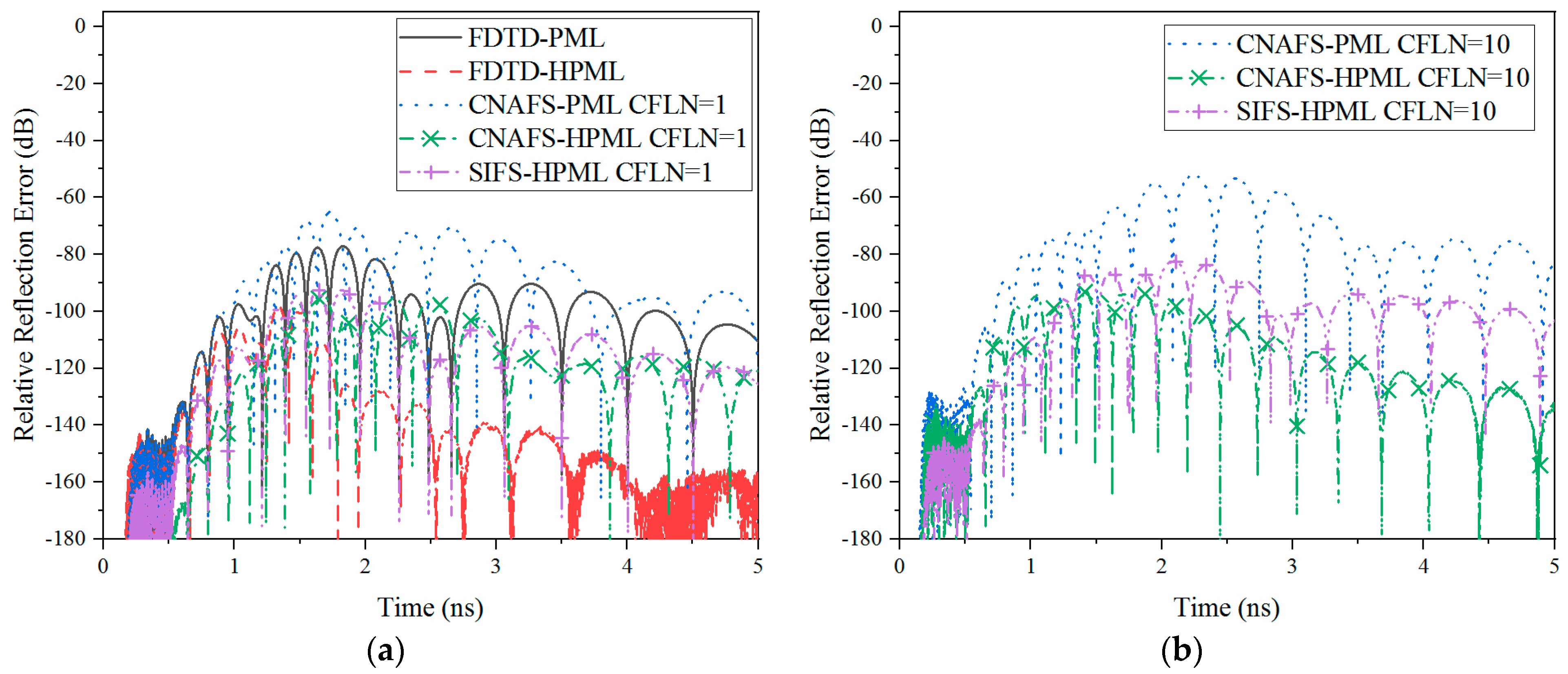
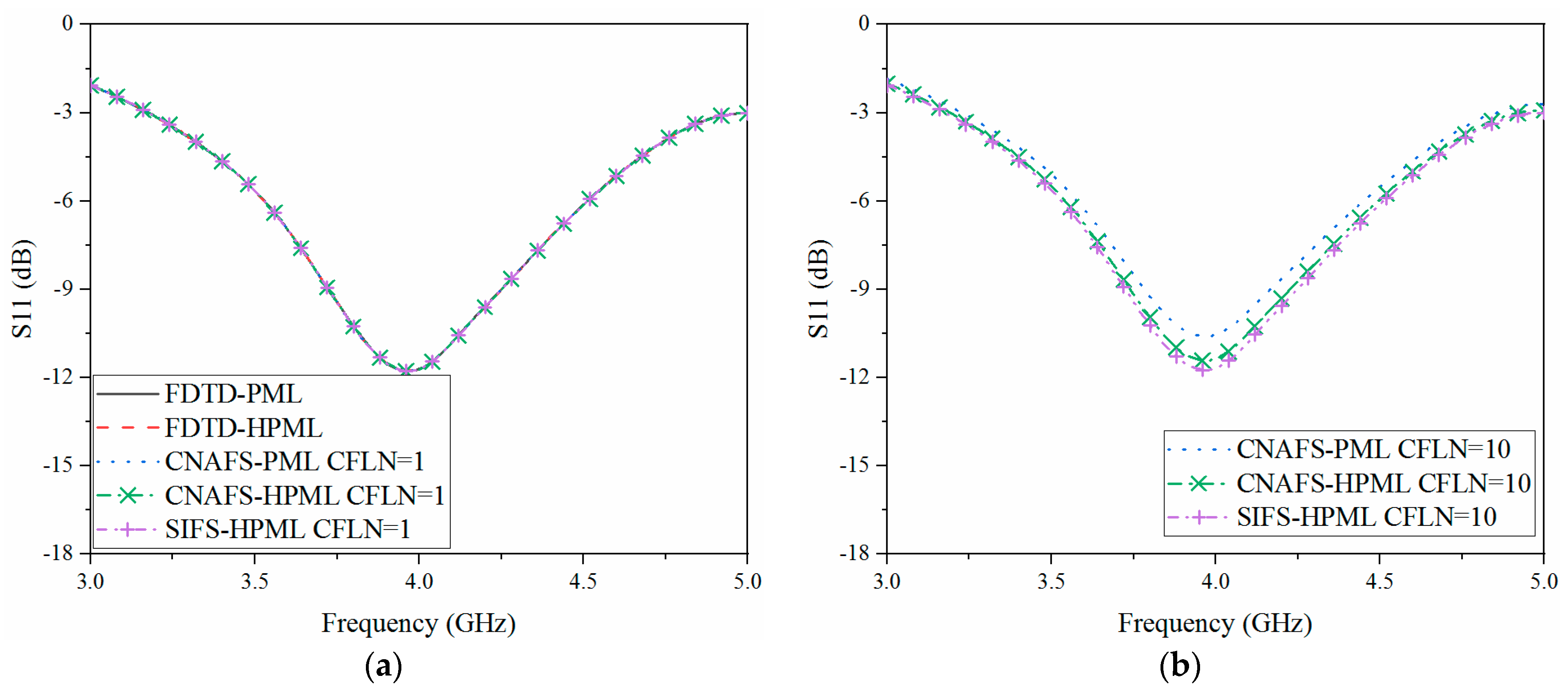
3.2. Wave Radiation Problem: Antenna Communication in the Plasma Sheath on the Surface of the Blackout Re-Entry Vehicle

As is demonstrated that the existence of plasma sheath shows a significant influence on the communication system. Among the communication system, the antenna is one of the most important elements. As shown in Figure 2 that the antenna model is located on the side surface of the vehicle. In order to demonstrate the influence of the plasma sheath, Figure 6 shows the computational domain of the antenna. The entire computational domain holds the dimensions of 20 × 20 × 10 mm3 in each direction. It can be observed that the antenna is situated on the surface of the vehicle which can be expressed by the PEC metal plate with the size of 10 × 10 × 1 mm3 in each direction. As shown in Figure 6, the monopole antenna with a length of 1.75 mm is located at the center of the domain. The modulated Gaussian source excites from the antenna with the center frequency and bandwidth of 4 GHz and 1 GHz, respectively. The rest part of the computational domain is filled with anisotropic magnetized plasma with the parameters of ω p = 2 π × 28.7 GHz, ω b = 1 × 10 11 GHz, and ν = 20 GHz. The boundaries of the computational domain are terminated by the 10-cell-PML regions which hold the best absorption both in time and frequency domains. The observation point is located at the left top corner with 1 cell from three sides of the PML regions.
In the unconditionally stable algorithms, mesh size can be chosen according to the calculation accuracy rather than the CFL condition. Thus, in order to satisfy the accuracy requirement of the extremely thin metal plate along the vertical z-direction, a uniform mesh size can be obtained as Δ x = Δ y = Δ z = Δ = 0.3 mm. According to the CFL condition, a maximum time step of the explicit algorithms can be chosen as Δ t max F D T D = 0 . 58 ps. In order to demonstrate the absorption of absorbing boundary condition, relative reflection error in the time domain is employed which can be defined as
R d B ( t ) = 20 log 10 [ | E z t ( t ) E z r ( t ) | | max { E z r ( t ) } | ]
where E z t ( t ) is the test solution which can be obtained directly at the observation point. E z r ( t ) is the reference solution that can be obtained by 20 times enlarged computational domain and 128-cell-PML regions. Due to the employment of a larger computational domain and thicker PML regions, reflection waves can be minimized without changing the relative position between the observation point and source whose solution is close to the reference solution. Figure 7 shows the relative reflection error obtained by different algorithms.
As shown in Figure 7a that the conventional explicit FDTD-HPML scheme holds the best performance due to the employment of higher-order formulation and explicit calculation procedure. With the employment of an implicit scheme, absorption decreases with the introduction of matrices at each time step. Among the implicit schemes, the proposed scheme almost holds the same performance compared with the original CNAFS-HPML scheme. Compared with the original CNAFS-PML and FDTD-PML schemes, absorption can be increased significantly. It can be concluded that the employment of higher-order formulation improves absorption, especially in late-time reflections. As shown in Figure 7b that the absorption decreases with the enlargement of time steps. The reason is that numerical dispersion increases in such circumstances resulting in a decrement in calculation accuracy and absorption. Meanwhile, it can be concluded that the proposed scheme still shows a similar performance compared with the original CNAFS-HPML scheme. Compared with the FDTD-PML, absorption still can be improved with larger time steps. The effectiveness of the calculation can also be reflected by the memory consumption, simulation duration, and time reduction obtained by different algorithms and CFLN which are shown in Table 2. As shown in Table 2, the explicit FDTD-PML and FDTD-HPML schemes hold the best calculation efficiency due to the free matrix form during the iteration. The implicit schemes including CNAFS and SIFS algorithms solve matrices at each time step resulting in the calculation being much more expensive from the aspects of memory consumption and simulation duration. Meanwhile, according to the higher-order formulation, memory consumption, and simulation duration also increase by multiplying stretched coordinate variables together into a single form. The simulation duration can be decreased by employing a larger CFLN to enlarge the simulation time step. It can be observed that the simulation duration can be further decreased with CFLN = 10. Meanwhile, compared with the CNAFS algorithm, the proposed SIFS algorithm can avoid repeated calculation of auxiliary variables, field components, and coefficients resulting in a decrement in simulation duration and memory storage.
The calculation accuracy and absorption can also be evaluated by the scattering parameters in the frequency domain. Figure 8 and Figure 9 shows the return loss (S11) with and without plasma sheath obtained by a different algorithm. As demonstrated in Figure 8a and Figure 9a that the curves are almost overlapped which indicates the same calculation accuracy with a small time step. From Figure 8b and Figure 9b, curves show shifting compared with that obtained by the explicit FDTD-HPML algorithm due to the increment of numerical dispersion with larger CFLNs. It can be observed that the proposed algorithm also holds the most considerable performance. As can be compared between Figure 8 and Figure 9 that the return loss varies with the existence of plasma sheath. Thus, the plasma sheath significantly affects the return loss parameters which results in the failure of the communication system.

4. Conclusions

Here, an unconditionally stable SIFS algorithm is proposed with higher order CPML formulation to efficiently analyze the re-entry vehicle at the hypersonic speed. The ADE method is modified according to the integer time step scheme to analyze the magnetized plasma. Multi-scale numerical examples including target characteristic problem and antenna radiation problem are carried out to demonstrate the effectiveness of the algorithm. The results indicates that the proposed SIFS algorithm can simplify the formulation which shows advantages in efficiency and memory consumption. The proposed CPML algorithm shows considerable absorption and accuracy both in time and frequency domains. Plasma sheath shows significant influence on the target characteristics and antenna performance which affects the communication and detection of the blackout re-entry vehicle.

Author Contributions

Conceptualization, Y.W.; Data curation, Y.W. and J.W.; Formal analysis, H.X. and H.X.; Funding acquisition, H.X. and J.W.; Investigation, Y.W. and J.W.; Methodology, H.X., Y.W. and J.W.; Project administration, H.X. and J.W.; Resources, H.X.; Software, H.X.; Validation, Y.W., H.X. and J.W.; Visualization, Y.W. and Y.W.; Writing—original draft, Y.W. and H.X.; Writing—review & editing, H.X., Y.W. and J.W. All authors have read and agreed to the published version of the manuscript.

Funding

This research received no external funding.

Data Availability Statement

Data available on request due to restrictions e.g., privacy or ethical.

Conflicts of Interest

The authors declare no conflict of interest.

Abbreviations

Approximate-Factorization-Splitting (AFS); Auxiliary Difference Equation (ADE); Complex-Frequency-Shifted (CFS); Convolutional PML (CPML); Courant–Friedrichs–Levy (CFL); Courant–Friedrichs–Levy Number (CFLN); Crank-Nicolson (CN); Directly-Splitting (DS); Digital Signal Processing (DSP); Finite-Difference Time-Domain (FDTD); Radar Cross Section (RCS); Return Loss (S11); System Incorporated Directly-Splitting (SIDS); Stretched Coordinate (SC).

References

  1. Takahashi, Y.; Nakasato, R.; Oshima, N. Analysis of Radio Frequency Blackout for a Blunt-Body Capsule in Atmospheric Reentry Missions. Aerospace 2016, 3, 2. [Google Scholar] [CrossRef]
  2. Webb, B.A.; Ziolkowski, R.W. A Metamaterial-Inspired Approach to Mitigating Radio Frequency Blackout When a Plasma Forms Around a Reentry Vehicle. Photonics 2020, 7, 88. [Google Scholar] [CrossRef]
  3. Yu, M.; Qiu, Z.; Lv, B.; Takahashi, Y. Multiphysics Mathematical Modeling and Flow Field Analysis of an Inflatable Membrane Aeroshell in Suborbital Reentry. Mathematics 2022, 10, 832. [Google Scholar] [CrossRef]
  4. Niu, G.; Liu, Y.; Bai, B.; Ding, Y.; Song, L.; Li, X. Polarization Scattering Characteristic of Plasma-Sheath-Covered Hypersonic Vehicle. IEEE Trans. Plasma Sci. 2023, 51, 641–648. [Google Scholar] [CrossRef]
  5. Wang, S.; Guo, L.-X.; Yu, Z.-F.; Wang, J.; Chen, J. Method of 2-D Range-Doppler Imaging for Plasma Wake Based on Range Walk Correction. IEEE Trans. Plasma Sci. 2023, 51, 1076–1084. [Google Scholar] [CrossRef]
  6. Ding, Y.; Bai, B.; Li, X.; Niu, G.; Liu, Y. Research on EM Shielding Mechanism of the Plasma-Sheath-Covered Target. IEEE Trans. Plasma Sci. 2023, 51, 632–640. [Google Scholar] [CrossRef]
  7. Liu, Y.; Zhang, S.; Song, Z.; Ma, J.; Jiang, T. Fast Analysis of the Electromagnetic Scattering of Targets Coated with Plasma Sheath Based on IBC. IEEE Antennas Wirel. Propag. Lett. 2021, 21, 491–495. [Google Scholar] [CrossRef]
  8. Liu, S.-H.; Guo, L.-X. Analyzing the Electromagnetic Scattering Characteristics for 3-D Inhomogeneous Plasma Sheath Based on PO Method. IEEE Trans. Plasma Sci. 2016, 44, 2838–2843. [Google Scholar] [CrossRef]
  9. Yee, K.S. Numerical solution of initial boundary value problems involving maxwell’s equations in isotropic media. IEEE Trans. Antennas Propag. 1966, 14, 302–307. [Google Scholar]
  10. Taflove, A.; Hagness, S.C. Computational Electrodynamics: The Finite-Difference Time Domain Method, 3rd ed.; Artech House: Norwood, MA, USA, 2005. [Google Scholar]
  11. Namiki, T. 3-D ADI-FDTD method-unconditionally stable time-domain algorithm for solving full vector Maxwell’s equations. IEEE Trans. Microw. Theory Tech. 2000, 48, 1743–1748. [Google Scholar] [CrossRef]
  12. Shibayama, J.; Nomura, A.; Ando, R.; Yamauchi, J.; Nakano, H. A Frequency-Dependent LOD-FDTD Method and Its Application to the Analyses of Plasmonic Waveguide Devices. IEEE J. Quantum Electron. 2009, 46, 40–49. [Google Scholar] [CrossRef] [Green Version]
  13. Chu, Q.; Kong, Y.-D. Three New Unconditionally-Stable FDTD Methods with High-Order Accuracy. IEEE Trans Antennas Propag. 2009, 57, 2675–2682. [Google Scholar]
  14. Chen, J.; Wang, J. A Three-Dimensional Semi-Implicit FDTD Scheme for Calculation of Shielding Effectiveness of Enclosure with Thin Slots. IEEE Trans. Electromagn. Compat. 2007, 49, 354–360. [Google Scholar] [CrossRef]
  15. Tan, E.L. From Time-Collocated to Leapfrog Fundamental Schemes for ADI and CDI FDTD Methods. Axioms 2022, 11, 23. [Google Scholar] [CrossRef]
  16. Pereda, J.A.; Serroukh, A.; Grande, A.; Vegas, A. Implementation of Absorbing Boundary Conditions Based on the Second-Order One-Way Wave Equation in the LOD- and the ADI-FDTD Methods. IEEE Antennas Wirel. Propag. Lett. 2012, 11, 981–983. [Google Scholar] [CrossRef]
  17. Tan, E.L. Fundamental Leapfrog ADI and CDI FDTD Methods. In Proceedings of the 2021 IEEE International Symposium on Antennas and Propagation and USNC-URSI Radio Science Meeting (APS/URSI), Singapore, 4–10 December 2021; pp. 643–644. [Google Scholar]
  18. Wang, X.-H.; Yin, W.-Y.; Chen, Z.D. One-step leapfrog ADI-FDTD method for anisotropic magnetized plasma. In Proceedings of the 2013 IEEE MTT-S International Microwave Symposium Digest (MTT), Seattle, WA, USA, 2–7 June 2013; pp. 1–4. [Google Scholar]
  19. Li, Y.; Wang, N.; Lei, J.; Wang, F.; Li, C. Modeling GPR Wave Propagation in Complex Underground Structures Using Conformal ADI-FDTD Algorithm. Appl. Sci. 2022, 12, 5219. [Google Scholar] [CrossRef]
  20. Liu, S.; Tan, E.L.; Zou, B.; Zhang, L. Higher Order CPML for Leapfrog Complying-Divergence Implicit FDTD Method and Its Numerical Properties. IEEE Trans. Microw. Theory Tech. 2022, 71, 522–535. [Google Scholar] [CrossRef]
  21. Sun, G.; Trueman, C.W. Approximate Crank-Nicolson scheme for the 2-D finite-difference time-domain method for TEz waves. IEEE Trans. Antennas Propag. 2004, 52, 2963–2972. [Google Scholar] [CrossRef]
  22. Sun, G.; Trueman, C.W. Unconditionally stable Crank-Nicolson scheme for solving two-dimensional Maxwell’s equations. Electron. Lett. 2003, 39, 595–597. [Google Scholar] [CrossRef]
  23. Wu, P.; Xie, Y.; Jiang, H.; Niu, L. Higher-Order Approximate CN-PML Theory for Magnetized Ferrite Simulations. Adv. Theory Simul. 2020, 3, 1900221. [Google Scholar] [CrossRef]
  24. Sun, G.; Trueman, C. Unconditionally-stable FDTD method based on Crank-Nicolson scheme for solving three-dimensional Maxwell equations. Electron. Lett. 2004, 40, 589–590. [Google Scholar] [CrossRef]
  25. Sun, G.; Trueman, C. Efficient implementations of the Crank-Nicolson scheme for the finite-difference time-domain method. IEEE Trans. Microw. Theory Tech. 2006, 54, 2275–2284. [Google Scholar] [CrossRef]
  26. Wu, P.; Wang, J.; Chen, J.; Jiang, H.; Xie, Y.; Natsuki, T. System incorporated direct-splitting algorithm for periodic nonuniform metamaterial design in open regions. Optik 2022, 271, 169812. [Google Scholar] [CrossRef]
  27. Wu, P.; Xie, Y.; Jiang, H.; Natsuki, T. Complex Envelope Approximate CN-PML Algorithm with Improved Absorption. IEEE Ante. Wirel. Propagat. Lett. 2020, 19, 1521–1525. [Google Scholar] [CrossRef]
  28. Wu, P.; Xie, Y.; Jiang, H.; Di, H.; Natsuki, T. Implicit Approximate Crank–Nicolson Theory for Anisotropic Ferrite Structure Simulation with Enhanced Absorption. Adv. Theory Simul. 2021, 4, 2000309. [Google Scholar] [CrossRef]
  29. Rezaee, M.R.; Niknam, A.; Ghomi, H.; Latifi, H. Magnetized plasma sheath dynamics in plasma source ion implantation. In Proceedings of the 2008 IEEE 35th International Conference on Plasma Science, Karlsruhe, Germany, 15–19 June 2008; p. 1. [Google Scholar] [CrossRef]
  30. Fang, Y.; Xi, X.-L.; Liu, J.-F.; Pu, Y.-R.; Zhang, J.-S. An Iterative WLP-FDTD Method for Wave Propagation in Magnetized Plasma. IEEE Trans. Plasma Sci. 2017, 45, 2215–2219. [Google Scholar] [CrossRef]
  31. Liu, S.; Liu, S. Runge-Kutta exponential time differencing FDTD method for anisotropic magnetized plasma. IEEE Antennas Wirel. Propag. Lett. 2008, 7, 306–309. [Google Scholar]
  32. Xu, L.; Yuan, N. JEC-FDTD for 2-D conducting cylinder coated by anisotropic magnetized plasma. IEEE Microw. Wirel. Compon. Lett. 2005, 15, 892–894. [Google Scholar] [CrossRef]
  33. Samimi, A.; Simpson, J.J. An Efficient 3-D FDTD Model of Electromagnetic Wave Propagation in Magnetized Plasma. IEEE Trans. Antennas Propag. 2015, 63, 269–279. [Google Scholar] [CrossRef]
  34. Berenger, J.P. A perfectly matched layer for the absorption of electromagnetic waves. J. Com. Phys. 1994, 11, 185–200. [Google Scholar] [CrossRef]
  35. Chew, W.C.; Weedon, W.H. A 3D perfectly matched medium from modified maxwell’s equations with stretched coordinates. Microw. Opt. Technol. Lett. 1994, 7, 599–604. [Google Scholar] [CrossRef]
  36. Kuzuoglu, M.; Mittra, R. Frequency dependence of the constitutive parameters of causal perfectly matched anisotropic absorbers. IEEE Microw. Guid. Wave Lett. 1996, 6, 447–449. [Google Scholar] [CrossRef]
  37. Gedney, S.; Liu, G.; Roden, J.; Zhu, A. Perfectly matched layer media with CFS for an unconditionally stable ADI-FDTD method. IEEE Trans. Antennas Propag. 2001, 49, 1554–1559. [Google Scholar] [CrossRef]
  38. Correia, D.; Jin, J.-M. Performance of regular PML, CFS-PML, and second-order PML for waveguide problems. Microw. Opt. Technol. Lett. 2006, 48, 2121–2126. [Google Scholar] [CrossRef]
  39. Berenger, J.P. Perfectly Matched Layer (PML) for Computational Electromagnetics; Morgan & Claypool: San Rafael, CA, USA, 2007. [Google Scholar]
  40. Giannopoulos, A. Higher-Order Convolution PML (CPML) for FDTD Electromagnetic Modeling. IEEE Trans. Antennas Propag. 2020, 68, 6226–6231. [Google Scholar] [CrossRef]
  41. Wu, S.; Sun, Y.; Chi, M.; Chen, X. Performance enhanced absorbing boundary condition for electromagnetic modelling and simulation. Int. J. Numer. Model. Electron. Netw. Devices Fields 2020, 33, e2760. [Google Scholar] [CrossRef]
  42. Wu, P.; Xie, Y.; Jiang, H.; Niu, L. Different implementations of material independent multi-order nearly perfectly matched layers for EM simulations. Microw. Opt. Technol. Lett. 2020, 62, 3485–3498. [Google Scholar] [CrossRef]
  43. Wu, P.; Wang, X.; Xie, Y.; Jiang, H.; Natsuki, T. Hybrid Implicit-Explicit Procedure With Improved Absorption for Anisotropic Magnetized Plasma in Bandpass Problem. IEEE J. Multiscale Multiphysics Comput. Tech. 2021, 6, 229–238. [Google Scholar] [CrossRef]
  44. Wu, P.Y.; Jiang, H.L.; Xie, Y.J.; Niu, L.Q. Three-Dimensional Higher Order PML Based on Alternating Direction Implicit Algorithm. IEEE Antennas Wirel. Propag. Lett. 2019, 18, 2592–2596. [Google Scholar] [CrossRef]
  45. Yu, Y.; Li, Q.; Liu, E.; Png, C.E.; Su, X. Simulation of dispersive plasmas using implicit and explicit ADE-FDTD schemes. In Proceedings of the 2015 IEEE 4th Asia-Pacific Conference on Antennas and Propagation (APCAP), Bali, Indonesia, 30 June–3 July 2015; pp. 128–129. [Google Scholar] [CrossRef]
  46. Wu, P.; Xie, Y.; Jiang, H.; Zhang, J.; Chen, J.; Natsuki, T. Complex Envelope Weaker HIE with Higher Order PML Algorithm for FDTD Simulation. IEEE Microw. Wirel. Technol. Lett. 2023, 33, 251–254. [Google Scholar] [CrossRef]
  47. Teixeira, M.; Rodriguez, D. A novel derivation of the Agarwal-Cooley fast cyclic convolution algorithm based on the Good-Thomas Prime Factor algorithm. In Proceedings of the 38th Midwest Symposium on Circuits and Systems, Rio de Janeiro, Brazil, 13–16 August 1995; Volume 1, pp. 89–91. [Google Scholar]
  48. Jiang, H.L.; Wu, L.T.; Zhang, X.G.; Wang, Q.; Wu, P.Y.; Liu, C.; Cui, T.J. Computationally Efficient CN-PML for EM Simulations. IEEE Trans. Microw. Theory Tech. 2019, 67, 4646–4655. [Google Scholar] [CrossRef]
  49. Wu, P.; Xie, Y.; Jiang, H.; Natsuki, T. Performance Enhanced Crank-Nicolson Boundary Conditions for EM Problems. IEEE Trans. Antennas Propag. 2020, 69, 1513–1527. [Google Scholar] [CrossRef]
  50. Haolin, J.; Yongjun, X.; Peiyu, W.; Jianfeng, Z.; Liqiang, N. Unsplit-field higher-order nearly PML for arbitrary media in EM simulation. J. Syst. Eng. Electron. 2021, 32, 1–6. [Google Scholar] [CrossRef]
  51. Li, J.; Yang, Q.; Niu, P.; Feng, N. An efficient implementation of the higher-order PML based on the Z-transform method. In Proceedings of the 2011 IEEE International Conference on Microwave Technology & Computational Electromagnetics, Beijing, China, 22–25 May 2011; pp. 414–417. [Google Scholar] [CrossRef]
  52. Jiang, H.L.; Cui, T.J. Efficient PML Implementation for Approximate CN-FDTD Method. IEEE Antennas Wirel. Propag. Lett. 2019, 18, 698–701. [Google Scholar] [CrossRef]
  53. Niu, L.; Xie, Y.; Gao, J.; Wu, P.; Jiang, H. Approximate Crank–Nicolson Algorithm with Higher-Order PML Implementation for Plasma Simulation in Open Region Problems. Int. J. Antennas Propag. 2021, 2021, 6618492. [Google Scholar] [CrossRef]
Figure 1. The flow chart and comparison of (a) the original CNAFS algorithm (b) the proposed SIFS and according to the DSP technique.
Electronics 12 02892 g001
Figure 2. The sketch picture of the re-entry vehicle and the location of the antenna on the surface (a) The whole view; (b) Front View.
Electronics 12 02892 g002
Figure 3. The sketch picture of the computational domain with the blackout re-entry vehicle.
Electronics 12 02892 g003
Figure 4. The RCS parameter with the variation of frequency with the plasma sheath obtained by different algorithms (a) CFLN = 1; (b) CFLN = 10.
Electronics 12 02892 g004
Figure 5. The RCS parameter with the variation of frequency without the plasma sheath obtained by different algorithms (a) CFLN = 1; (b) CFLN = 10.
Electronics 12 02892 g005
Figure 6. The sketch picture of the antenna system in the plasma sheath on the surface of the flight.
Electronics 12 02892 g006
Figure 7. The relative reflection error parameter with the variation of frequency with the plasma sheath obtained by different algorithms (a) CFLN = 1; (b) CFLN = 10.
Electronics 12 02892 g007
Figure 8. The S11 parameter with the variation of frequency with the plasma sheath obtained by different algorithms (a) CFLN = 1; (b) CFLN = 10.
Electronics 12 02892 g008
Figure 9. The S11 parameter with the variation of frequency without the plasma sheath obtained by different algorithms (a) CFLN = 1; (b) CFLN = 10.
Electronics 12 02892 g009
Table 1. The memory consumption, simulation duration, and time reduction obtained by different algorithms and CFLN of the RCS problem.
AlgorithmsCFLNStepsMemory (G)Time (min)Reduction (%)
FDTD-PML13276827.543.4-
FDTD-HPML13276835.991.7−111.3
CNAFS-PML13276840.4372.3−757.8
CNAFS-HPML13276853.1440.1−1006.2
SIFS-HPML13276847.3389.5−785.9
CNAFS-PML10327740.421.949.5
CNAFS-HPML10327753.126.439.2
SIFS-HPML10327747.322.149.1
Table 2. The memory consumption, simulation duration, and time reduction obtained by different algorithms and CFLN in the antenna radiation problem.
AlgorithmsCFLNStepsMemory (G)Time (min)Reduction (%)
FDTD-PML1327681.14.7-
FDTD-HPML1327681.922.3−377.5
CNAFS-PML1327682.575.1−1497.9
CNAFS-HPML1327683.090.4−1823.4
SIFS-HPML1327682.681.6−1636.2
CNAFS-PML1032772.52.644.7
CNAFS-HPML1032773.04.112.8
SIFS-HPML1032772.33.329.8
Disclaimer/Publisher’s Note: The statements, opinions and data contained in all publications are solely those of the individual author(s) and contributor(s) and not of MDPI and/or the editor(s). MDPI and/or the editor(s) disclaim responsibility for any injury to people or property resulting from any ideas, methods, instructions or products referred to in the content.

