
Generative Design of the Architecture Platform in Multiprocessor System Design

Abstract
:1. Introduction
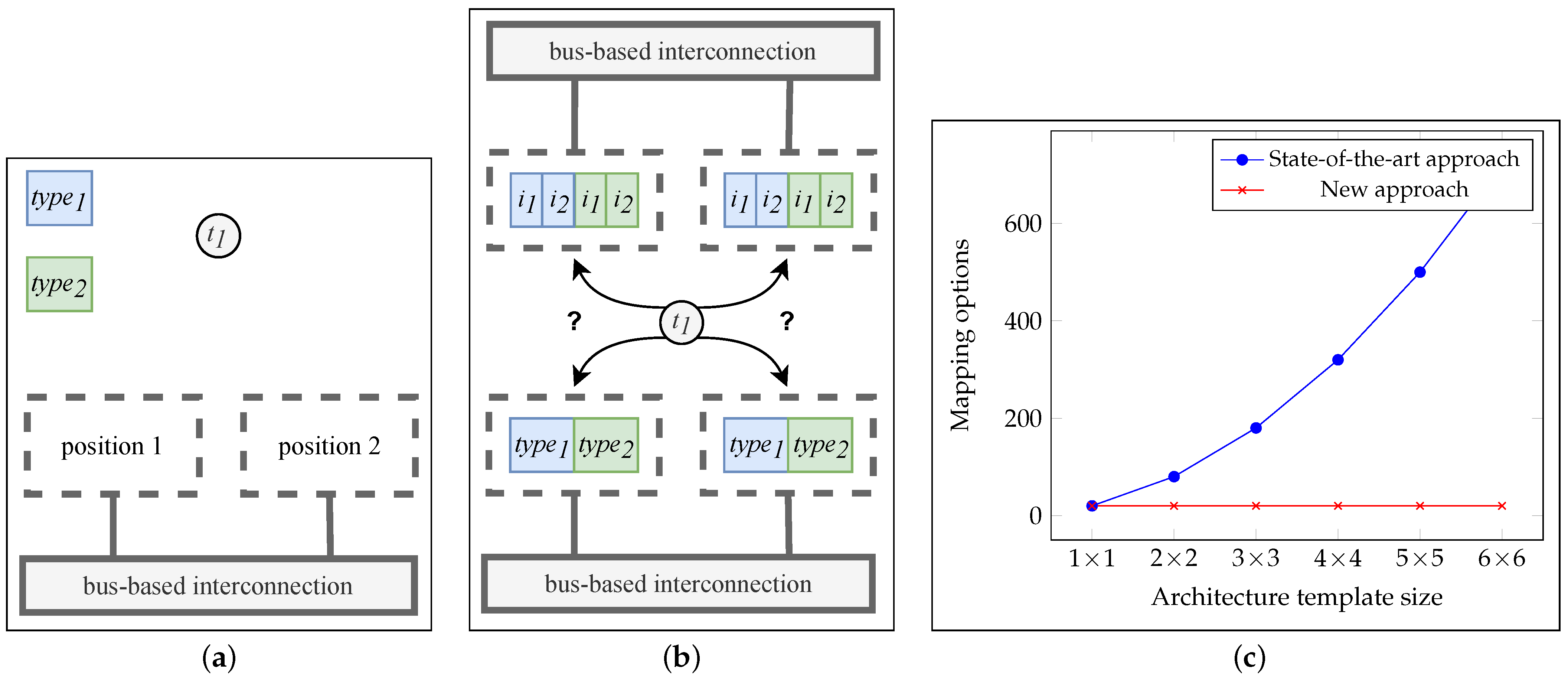
- How many processing units are required for an optimal execution of the given application?
- Which processing types are required for an optimal execution of the given application?
- What is an efficient distribution of tasks from an application onto processing units?
- How do we organize the communication structure to enable an efficient synchronization of the given processes?
- How can we efficiently encode a GDA at the ESL using ASP?
- How well is this problem solvable for various problem sizes?
- What might be challenges on the way to an unrestricted generative design at the ESL?
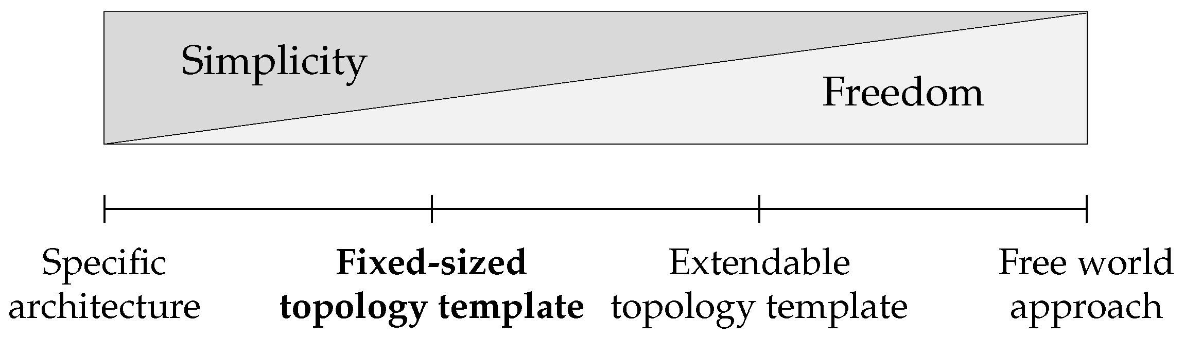
2. Related Work
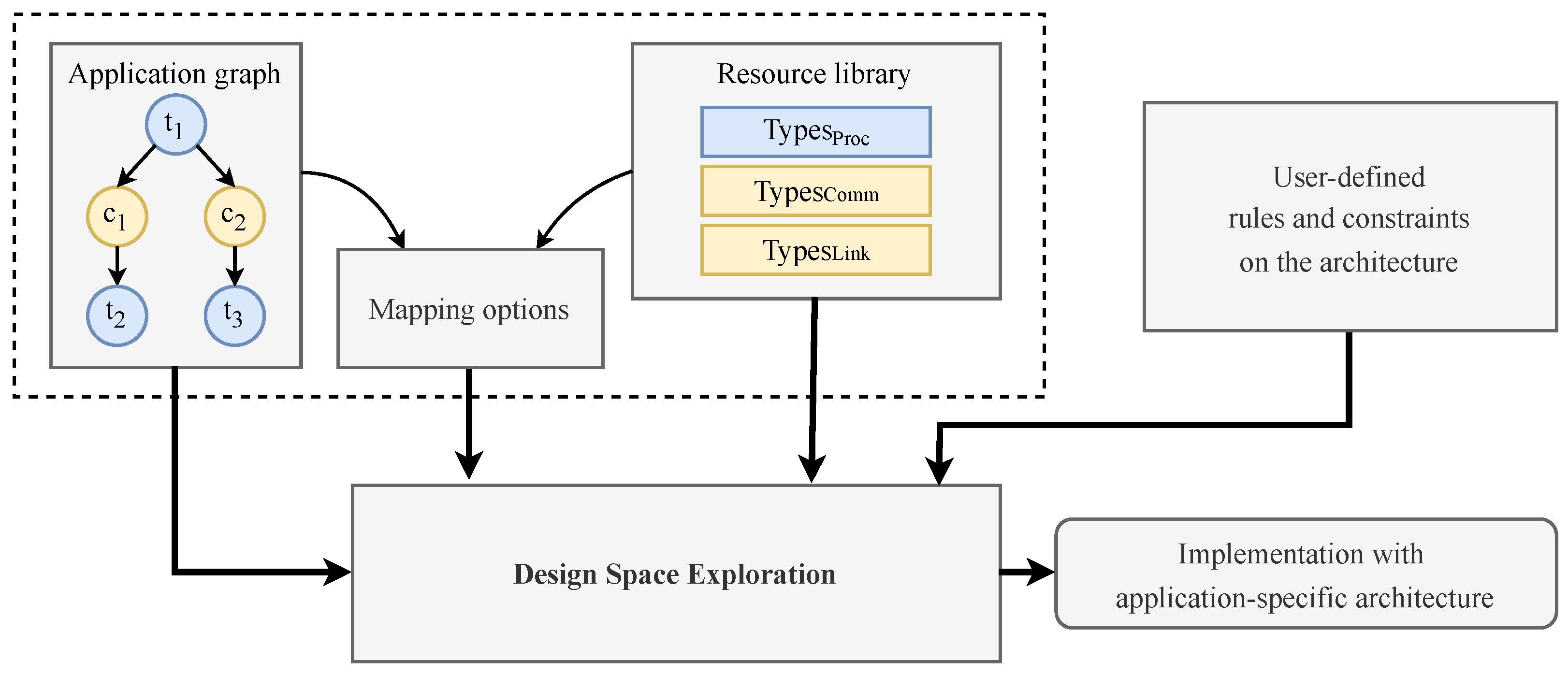
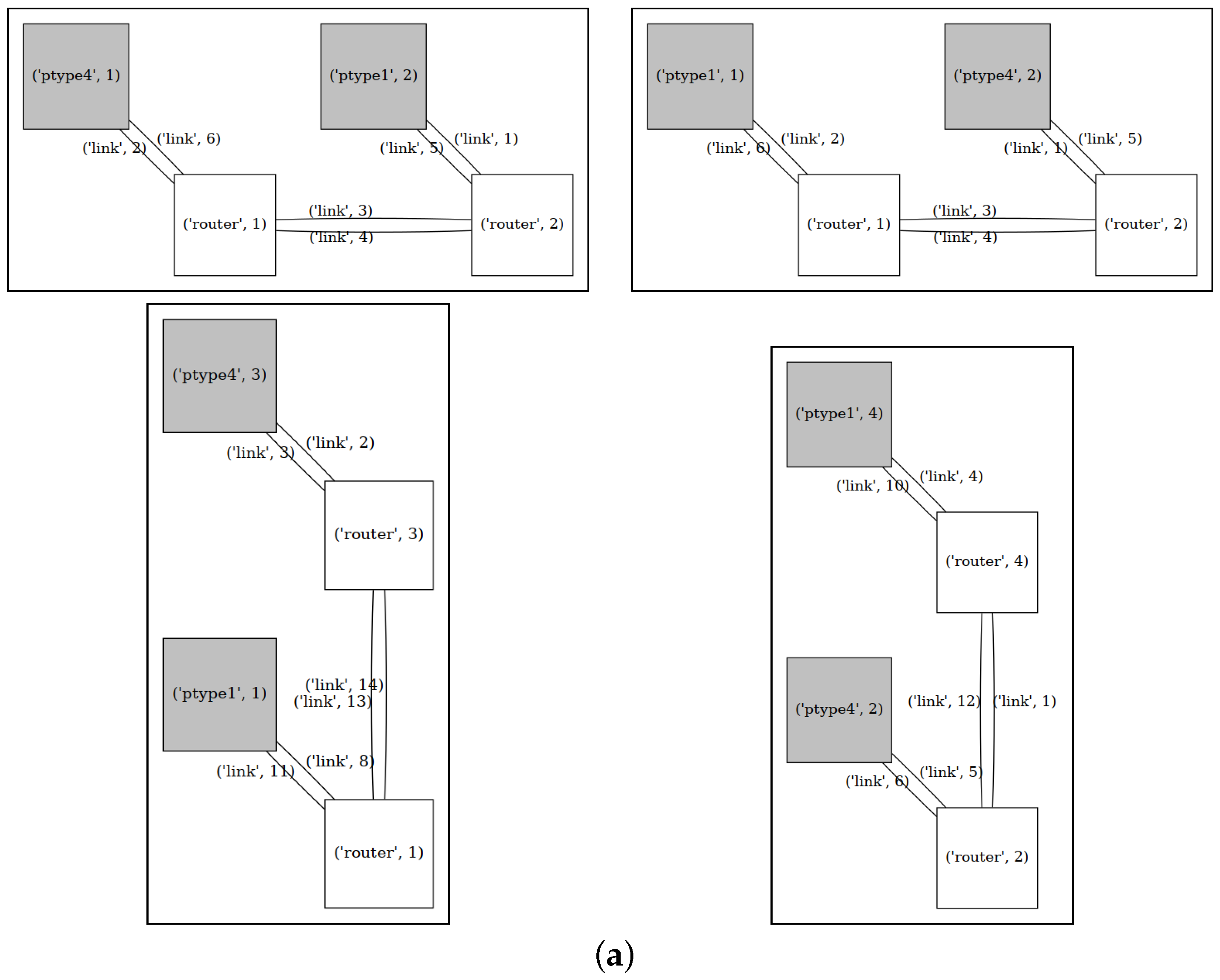
3. System Model
4. Exploration Model
4.1. System Synthesis
4.2. Architecture Exploration
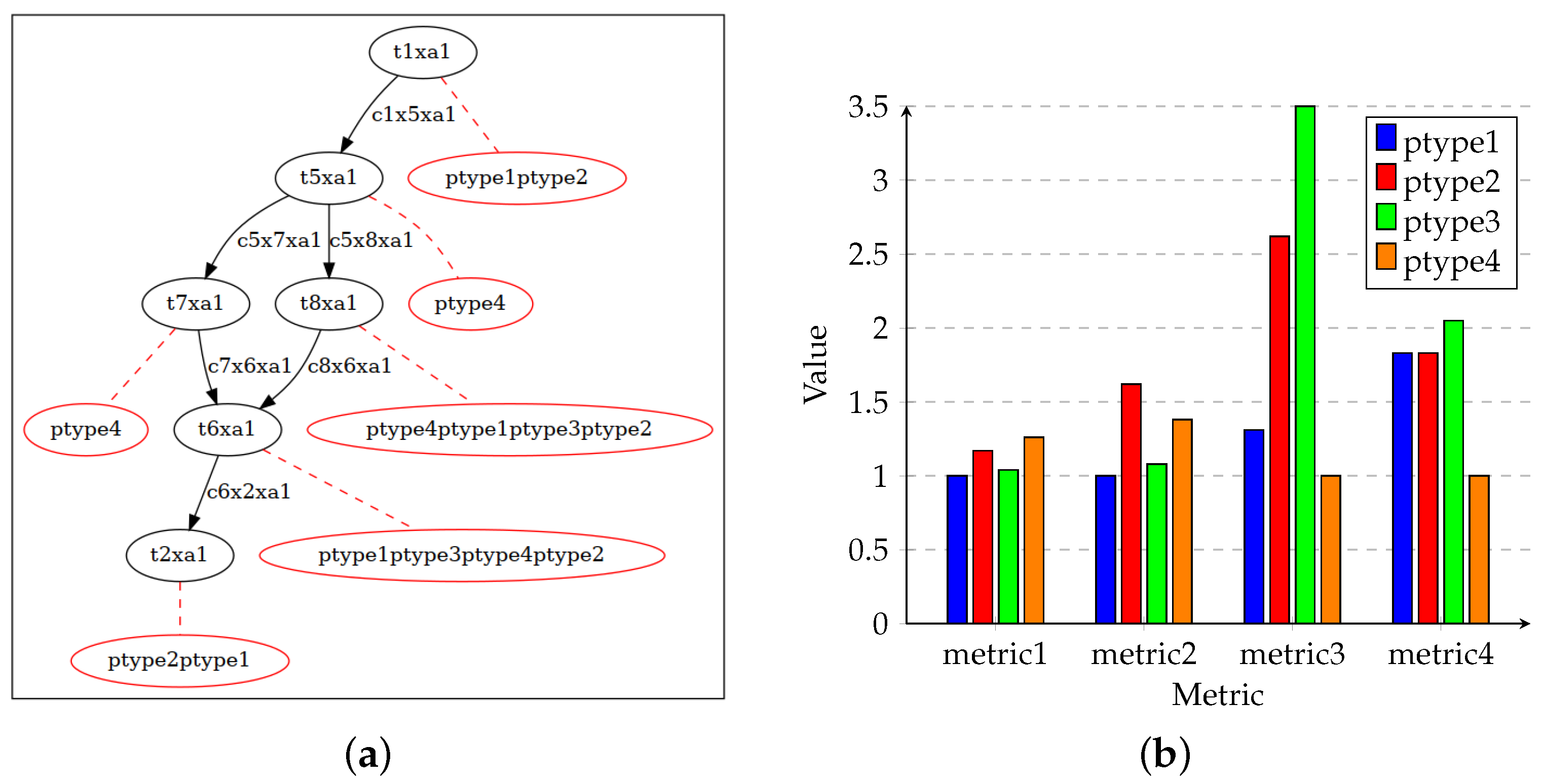
4.3. Encoding in ASP
| Listing 1: Exemplary facts representing aspects of the system’s specification. |
 |
| Listing 2: Exemplary rule and integrity constraint. |
 |
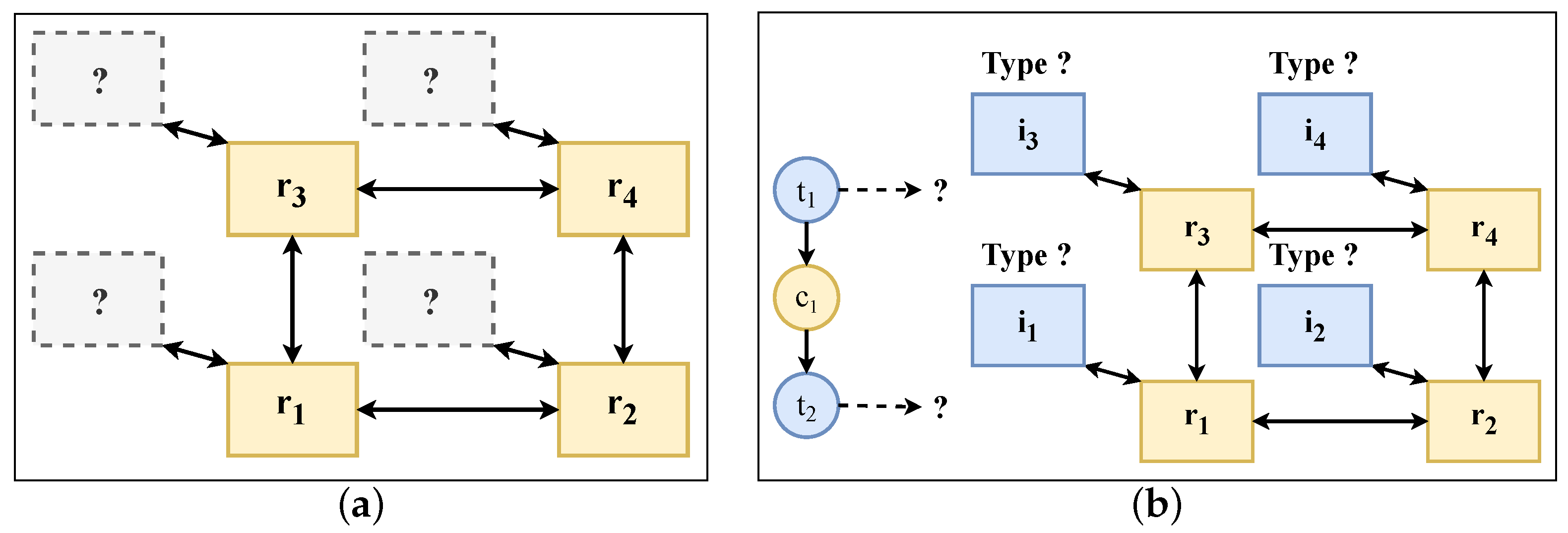
| Listing 3: Introduction of position numbering to identify positions in the grid. |
 |
- For each task T of the application graph, exactly one binding to a place in the hardware grid based on the implicit position numbering NR is selected (line two).
- For each implicit position number NR in the architecture template, a maximum of one processing type TYPE from the resource library is selected (line three).
| Listing 4: Problem description of the processing type instance selection and positioning as well as of the task binding. |
 |
| Listing 5: Additional constraints required to ensure valid solutions. |
 |
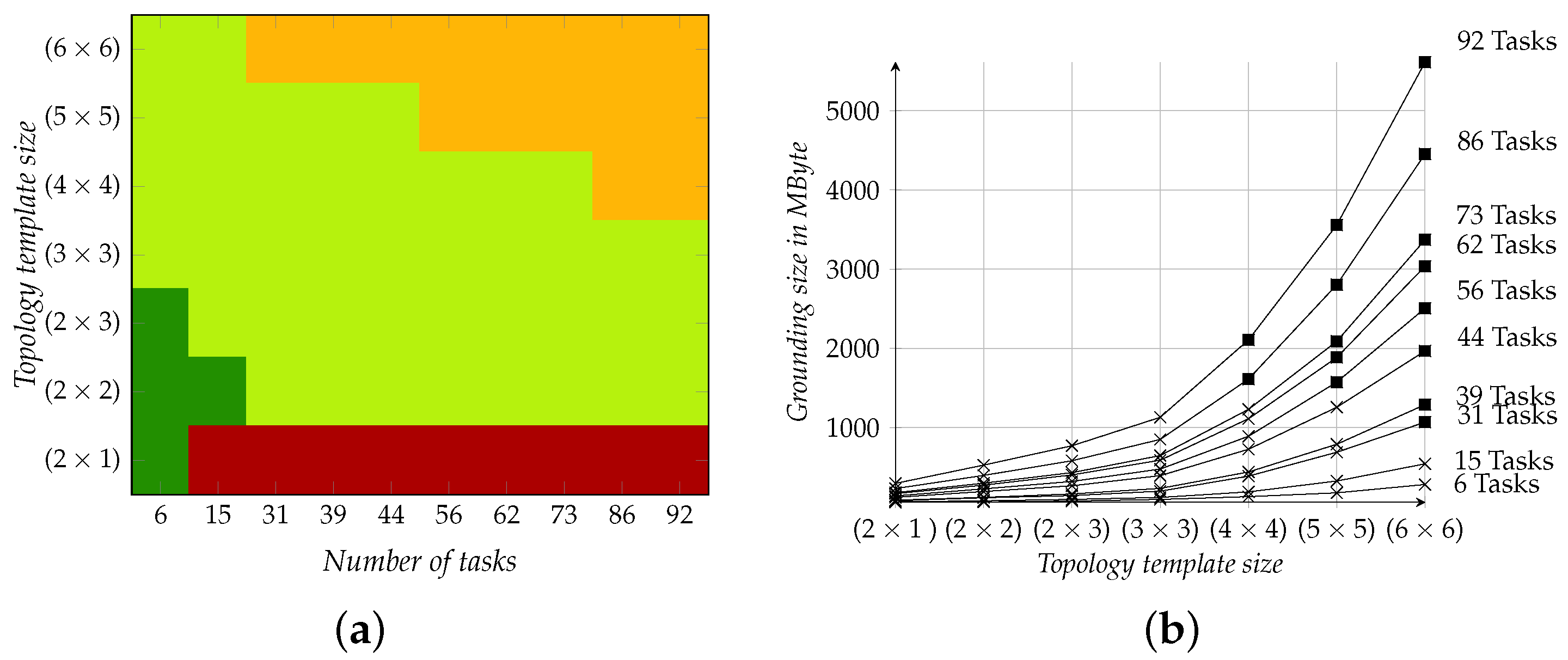
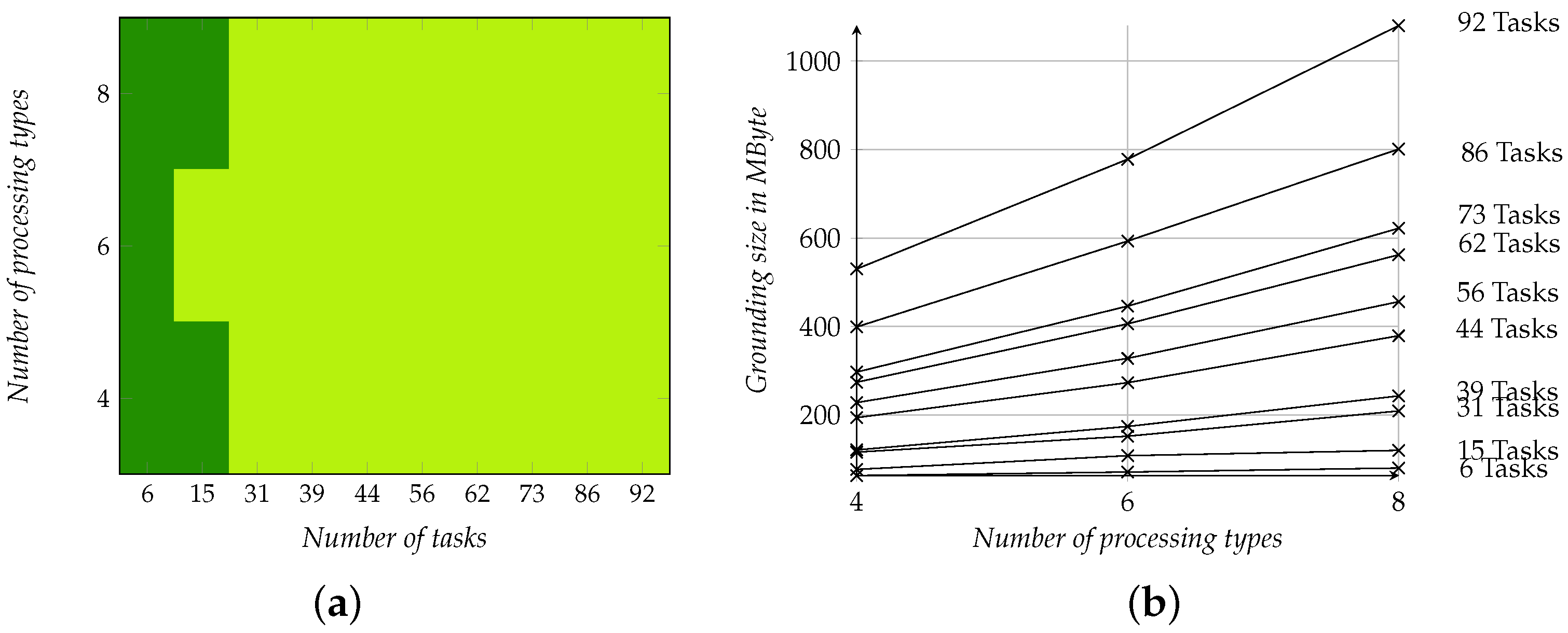
5. Simulation Study
5.1. Simulation Setup
5.2. Results
6. Discussion and Conclusion
- How can we efficiently encode a GDA at the ESL using ASP?
- How well is this problem solvable for various problem sizes?
- What might be challenges on the way to an unrestricted generative design at the ESL?
Author Contributions
Funding
Data Availability Statement
Conflicts of Interest
References
- Lukasiewycz, M.; Glass, M.; Haubelt, C.; Teich, J. Efficient Symbolic Multi-Objective Design Space Exploration. In Proceedings of the 2008 Asia and South Pacific Design Automation Conference, Seoul, Republic of Korea, 21–24 March 2008; IEEE: Piscataway, NJ, USA, 2008; pp. 691–696. [Google Scholar] [CrossRef]
- Andres, B.; Gebser, M.; Schaub, T.; Haubelt, C.; Reimann, F.; Glaß, M. Symbolic System Synthesis Using Answer Set Programming. In Proceedings of the Logic Programming and Nonmonotonic Reasoning, Corunna, Spain, 15–19 September 2013; pp. 79–91. [Google Scholar] [CrossRef]
- Neubauer, K.; Wanko, P.; Schaub, T.; Haubelt, C. Exact Multi-Objective Design Space Exploration Using ASPmT. In Proceedings of the 2018 Design, Automation & Test in Europe Conference & Exhibition (DATE), Dresden, Germany, 19–23 March 2018; IEEE: Piscataway, NJ, USA, 2018; pp. 257–260. [Google Scholar] [CrossRef]
- Ishebabi, H.; Mahr, P.; Bobda, C.; Gebser, M.; Schaub, T. Answer Set versus Integer Linear Programming for Automatic Synthesis of Multiprocessor Systems from Real-Time Parallel Programs. Int. J. Reconfig. Comput. 2009, 2009, 863630. [Google Scholar] [CrossRef]
- Lukasiewycz, M.; Sagstetter, F.; Steinhorst, S. Efficient Design Space Exploration of Embedded Platforms. In Proceedings of the 52nd Annual Design Automation Conference, San Francisco, CA, USA, 7–11 June 2015; pp. 1–6. [Google Scholar] [CrossRef]
- Richthammer, V.; Fassnacht, F.; Glaß, M. Search-Space Decomposition for System-level Design Space Exploration of Embedded Systems. ACM Trans. Des. Autom. Electron. Syst. 2020, 25, 14. [Google Scholar] [CrossRef]
- Goens, A.; Menard, C.; Castrillon, J. On the Representation of Mappings to Multicores. In Proceedings of the 2018 IEEE 12th International Symposium on Embedded Multicore/Many-core Systems-on-Chip (MCSoC), Hanoi, Vietnam, 12–14 September 2018; pp. 184–191. [Google Scholar] [CrossRef]
- Weichslgartner, A.; Gangadharan, D.; Wildermann, S.; Glaß, M.; Teich, J. DAARM: Design-time Application Analysis and Run-Time Mapping for Predictable Execution in Many-Core Systems. In Proceedings of the 2014 International Conference on Hardware/Software Codesign and System Synthesis (CODES+ISSS), New Delhi, India, 12–17 October 2014; pp. 1–10. [Google Scholar] [CrossRef]
- Schwarzer, T.; Weichslgartner, A.; Glaß, M.; Wildermann, S.; Brand, P.; Teich, J. Symmetry-Eliminating Design Space Exploration for Hybrid Application Mapping on Many-Core Architectures. IEEE Trans. Comput. Aided Des. Integr. Circuits Syst. 2018, 37, 297–310. [Google Scholar] [CrossRef]
- Haubelt, C.; Müller, L.; Neubauer, K.; Schaub, T.; Wanko, P. Evolutionary System Design with Answer Set Programming. Algorithms 2023, 16, 179. [Google Scholar] [CrossRef]
- Lukasiewycz, M.; Streubuhr, M.; Glass, M.; Haubelt, C.; Teich, J. Combined System Synthesis and Communication Architecture Exploration for MPSoCs. In Proceedings of the 2009 Design, Automation & Test in Europe Conference & Exhibition, Nice, France, 20–24 April 2009; IEEE: Piscataway, NJ, USA, 2009; pp. 472–477. [Google Scholar] [CrossRef]
- Gradišar, L.; Klinc, R.; Turk, Ž.; Dolenc, M. Generative Design Methodology and Framework Exploiting Designer-Algorithm Synergies. Buildings 2022, 12, 2194. [Google Scholar] [CrossRef]
- Li, H.; Lachmayer, R. Automated Exploration of Design Solution Space Applying the Generative Design Approach. In Proceedings of the Design Society: International Conference on Engineering Design, Delft, The Netherlands, 5–8 August 2019; Volume 1, pp. 1085–1094. [Google Scholar] [CrossRef]
- Pioneering Bionic 3D Printing|Airbus. Available online: https://www.airbus.com/en/newsroom/news/2016-03-pioneering-bionic-3d-printing (accessed on 8 February 2024).
- Generatives Design bei Airbus|Kundenprojekte|Autodesk. Available online: https://www.autodesk.de/customer-stories/airbus (accessed on 23 January 2024).
- Khan, S.; Gunpinar, E.; Sener, B. GenYacht: An Interactive Generative Design System for Computer-Aided Yacht Hull Design. Ocean Eng. 2019, 191, 106462. [Google Scholar] [CrossRef]
- Weaver, C.; Krishna, R.; Wu, L.; Austin, T. Application Specific Architectures: A Recipe for Fast, Flexible and Power Efficient Designs. In Proceedings of the 2001 International Conference on Compilers, Architecture, and Synthesis for Embedded Systems, Atlanta, GA, USA, 16–17 November 2001; pp. 181–185. [Google Scholar] [CrossRef]
- Gries, M. Methods for Evaluating and Covering the Design Space during Early Design Development. Integration 2004, 38, 131–183. [Google Scholar] [CrossRef]
- Pimentel, A.D. Methodologies for Design Space Exploration. In Handbook of Computer Architecture; Chattopadhyay, A., Ed.; Springer: Singapore, 2022; pp. 1–31. [Google Scholar] [CrossRef]
- Neubauer, K. Model-Based Symbolic Design Space Exploration at the Electronic System Level: A Systematic Approach. Ph.D. Thesis, University of Rostock, Rostock, Germany, 2021. [Google Scholar] [CrossRef]
- Thompson, M.; Pimentel, A.D. Exploiting Domain Knowledge in System-Level MPSoC Design Space Exploration. J. Syst. Archit. 2013, 59, 351–360. [Google Scholar] [CrossRef]
- Richthammer, V.; Scheinert, T.; Glaß, M. Data Mining in System-Level Design Space Exploration of Embedded Systems. In Embedded Computer Systems: Architectures, Modeling, and Simulation; Orailoglu, A., Jung, M., Reichenbach, M., Eds.; Springer International Publishing: Cham, Switzerland, 2020; Volume 12471, pp. 52–66. [Google Scholar] [CrossRef]
- Falkner, A.; Friedrich, G.; Schekotihin, K.; Taupe, R.; Teppan, E.C. Industrial Applications of Answer Set Programming. KI Künstliche Intell. 2018, 32, 165–176. [Google Scholar] [CrossRef]
- Blickle, T.; Teich, J.; Thiele, L. System-Level Synthesis Using Evolutionary Algorithms. Des. Autom. Embed. Syst. 1998, 3, 23–58. [Google Scholar] [CrossRef]
- Todorov, V.; Mueller-Gritschneder, D.; Reinig, H.; Schlichtmann, U. Deterministic Synthesis of Hybrid Application-Specific Network-on-Chip Topologies. IEEE Trans. Comput. Aided Des. Integr. Circuits Syst. 2014, 33, 1503–1516. [Google Scholar] [CrossRef]
- Li, Z.; Huang, J.; Xu, Q.; Chen, S. Integer linear programming based fault-tolerant topology synthesis for application-specific NoC. In Proceedings of the 2017 IEEE 12th International Conference on ASIC (ASICON), Guiyang, China, 25–28 October 2017; pp. 96–99. [Google Scholar] [CrossRef]
- Murali, S.; Benini, L.; De Micheli, G. An Application-Specific Design Methodology for On-Chip Crossbar Generation. IEEE Trans. Comput. Aided Des. Integr. Circuits Syst. 2007, 26, 1283–1296. [Google Scholar] [CrossRef]
- Thiele, L.; Chakraborty, S.; Gries, M.; Künzli, S. Design Space Exploration of Network Processor Architectures. Netw. Process. Des. Issues Pract. 2002, 1, 55–89. [Google Scholar] [CrossRef]
- Lieverse, P.; Van Der Wolf, P.; Vissers, K.; Deprettere, E. A Methodology for Architecture Exploration of Heterogeneous Signal Processing Systems. J. VLSI Signal Process. Syst. Signal Image Video Technol. 2001, 29, 197–207. [Google Scholar] [CrossRef]
- Ishebabi, H.; Bobda, C. Automated Architecture Synthesis for Parallel Programs on FPGA Multiprocessor Systems. Microprocess. Microsyst. 2009, 33, 63–71. [Google Scholar] [CrossRef]
- Lahti, S.; Sjovall, P.; Vanne, J.; Hamalainen, T.D. Are We There Yet? A Study on the State of High-Level Synthesis. IEEE Trans. Comput. Aided Des. Integr. Circuits Syst. 2019, 38, 898–911. [Google Scholar] [CrossRef]
- Bansal, S.; Hsiao, H.; Czajkowski, T.; Anderson, J.H. High-Level Synthesis of Software-Customizable Floating-Point Cores. In Proceedings of the 2018 Design, Automation & Test in Europe Conference & Exhibition (DATE), Dresden, Germany, 19–23 March 2018; pp. 37–42. [Google Scholar] [CrossRef]
- Neubauer, K.; Haubelt, C.; Wanko, P.; Schaub, T. Systematic Test Case Instance Generation for the Assessment of System-level Design Space Exploration Approaches. In Proceedings of the Workshop Methoden Und Beschreibungssprachen Zur Modellierung Und Verifikation von Schaltungen Und Systemen, Tübingen, Germany, 14 March 2018; p. 10. [Google Scholar] [CrossRef]
- Pasricha, S.; Dutt, N. On-Chip Communication Architectures: System on Chip Interconnect; Morgan Kaufmann: Burlington, MA, USA, 2010. [Google Scholar]
- Kaminski, R.; Romero, J.; Schaub, T.; Wanko, P. How to Build Your Own ASP-based System?! Theory Pract. Log. Program. 2021, 23, 299–361. [Google Scholar] [CrossRef]
- Lifschitz, V. Answer Set Programming; Springer International Publishing: Cham, Switzerland, 2019. [Google Scholar] [CrossRef]
- Zitzler, E.; Thiele, L.; Laumanns, M.; Fonseca, C.; da Fonseca, V. Performance Assessment of Multiobjective Optimizers: An Analysis and Review. IEEE Trans. Evol. Comput. 2003, 7, 117–132. [Google Scholar] [CrossRef]
- Hahn, S.; Sabuncu, O.; Schaub, T.; Stolzmann, T. Clingraph: ASP-Based Visualization. In Proceedings of the Logic Programming and Nonmonotonic Reasoning, Genova, Italy, 5–9 September 2022; Springer International Publishing: Cham, Switzerland, 2022; pp. 401–414. [Google Scholar] [CrossRef]
- Goens, A.; Siccha, S.; Castrillon, J. Symmetry in Software Synthesis. ACM Trans. Archit. Code Optim. 2017, 14, 20. [Google Scholar] [CrossRef]


| Component | Instances |
|---|---|
| Application | Containing 6, 15, 31, 39, 44, 56, 62, 73, 86, or 92 tasks |
| Topology | Containing a (), (), (), (), (), (), or () grid |
| Library | Containing 4, 6, or 8 processing types |
| Case | Grounding | First Solution | Overall Search | ||
|---|---|---|---|---|---|
| () | 0.23 s | 0.00 s | 0.25 s | 1.00 | 1.14 |
| ± 3.02 % | ± 0.00 % | ± 2.78 % | ± 0.00 % | ± 0.00 % | |
| () | 1.01 s | 0.00 s | 3.96 s | 1.00 | 1.00 |
| ± 1.70 % | ± 0.00 % | ± 1.01 % | ± 0.00 % | ± 0.00 % | |
| () | 2.39 s | 0.00 s | 767.55 s | 1.00 | 1.00 |
| ± 5.79 % | ± 0.00 % | ± 3.68 % | ± 0.00 % | ± 0.00 % | |
| () | 5.59 s | 0.07 s | 3600.00 s | 1.00 | 1.00 |
| ± 6.36 % | ± 0.00 % | ± 0.00 % | ± 0.00 % | ± 0.00 % | |
| () | 17.97 s | 5.62 s | 3600.00 s | 0.82 | 2.47 |
| ± 2.80 % | ± 2.49 % | ± 0.00 % | ± 0.00 % | ± 0.00 % | |
| () | 44.26 s | 10.34 s | 3600.00 s | 0.86 | 2.01 |
| ± 3.43 % | ± 4.72 % | ± 0.00 % | ± 0.00 % | ± 0.00 % | |
| () | 93.89 s | 19.76 s | 3600.00 s | 0.73 | 2.34 |
| ± 2.51 % | ± 13.8 % | ± 0.00 % | ± 0.00 % | ± 0.00 % |
Disclaimer/Publisher’s Note: The statements, opinions and data contained in all publications are solely those of the individual author(s) and contributor(s) and not of MDPI and/or the editor(s). MDPI and/or the editor(s) disclaim responsibility for any injury to people or property resulting from any ideas, methods, instructions or products referred to in the content. |
© 2024 by the authors. Licensee MDPI, Basel, Switzerland. This article is an open access article distributed under the terms and conditions of the Creative Commons Attribution (CC BY) license (https://creativecommons.org/licenses/by/4.0/).
Share and Cite
Müller, L.; Schumacher, N.; Steffen, L.; Haubelt, C. Generative Design of the Architecture Platform in Multiprocessor System Design. Electronics 2024, 13, 1404. https://doi.org/10.3390/electronics13071404
Müller L, Schumacher N, Steffen L, Haubelt C. Generative Design of the Architecture Platform in Multiprocessor System Design. Electronics. 2024; 13(7):1404. https://doi.org/10.3390/electronics13071404
Chicago/Turabian StyleMüller, Luise, Nico Schumacher, Lukas Steffen, and Christian Haubelt. 2024. "Generative Design of the Architecture Platform in Multiprocessor System Design" Electronics 13, no. 7: 1404. https://doi.org/10.3390/electronics13071404