Article

Development of Local Path Planning Using Selective Model Predictive Control, Potential Fields, and Particle Swarm Optimization

Korea Institute of Machinery and Materials, Daejeon 34103, Republic of Korea
*
Author to whom correspondence should be addressed.
Robotics 2024, 13(3), 46; https://doi.org/10.3390/robotics13030046
Submission received: 31 January 2024 / Revised: 4 March 2024 / Accepted: 6 March 2024 / Published: 8 March 2024
(This article belongs to the Special Issue Autonomous Navigation of Mobile Robots in Unstructured Environments)

Abstract

:
This paper focuses on the real-time obstacle avoidance and safe navigation of autonomous ground vehicles (AGVs). It introduces the Selective MPC-PF-PSO algorithm, which includes model predictive control (MPC), Artificial Potential Fields (APFs), and particle swarm optimization (PSO). This approach involves defining multiple sets of coefficients for adaptability to the surrounding environment. The simulation results demonstrate that the algorithm is appropriate for generating obstacle avoidance paths. The algorithm was implemented on the ROS platform using NVIDIA’s Jetson Xavier, and driving experiments were conducted with a steer-type AGV. Through measurements of computation time and real obstacle avoidance experiments, it was shown to be practical in the real world.

1. Introduction

Autonomous driving vehicles are a subject of active research worldwide, particularly in the fields of indoor and outdoor robots, automobiles, space robot, and the military. The primary objectives of this research are efficient exploration, saving time, and safety. Various ideas are being researched and presented to achieve these goals.
Autonomous driving consists of three main components: environmental awareness, path planning, and driving control [1]. Environmental awareness involves the use of sensors, such as cameras and LiDAR, to perceive surroundings. Path planning incorporates various methodologies, including graph-search-based, sampling-based, interpolation-based, and optimization-based methods [1]. These techniques aim to formulate a safe driving path based on the information gathered from environmental awareness.
Graph-search-based methods create nodes within the domain and construct a graph [2], which includes algorithms like Dijkstra [3] for finding the shortest path and A-Star [4] for determining the optimal path, using heuristic techniques. Sampling-based approaches randomly sample and connect points within the surrounding space [5]. Examples of such methods include the probabilistic roadmap method [6] and the rapidly explored random tree method [7]. Interpolation-based methods define a function using multiple coefficients and determine these coefficients [8]. Optimization-based methods formulate an optimization problem with constraints and cost functions to find a path that minimizes the cost. Examples of such methods include the potential field algorithm [9,10] and model predictive control (e.g., [11]).
The potential field algorithm is widely employed for real-time collision-free path planning [12]. In this approach, an attractive force is generated in the direction of the goal, while a repulsive force emanates from obstacles. Despite its frequent use due to its mathematical simplicity, issues such as local minima and oscillations around obstacles have been encountered [12]. Sfeir [13] introduced new formulas to mitigate these oscillations and prevent conflicts when obstacles are situated near a target. Kim [14,15] proposed a novel framework for escaping local minima in a robot’s path using the potential field method.
Path planning using model predictive control (MPC) is being studied as one of the important technologies in mobility systems such as autonomous vehicles and robots. MPC-based path planning solves an optimization problem for a set of future control inputs, creating a stable, collision-free, and efficient path.
However, there are still issues with path generation using MPC. The first issue is how to describe obstacles, and the second is the calculation of the optimization problem in MPC [16]. Recently, attempts have been made to integrate Artificial Potential Fields (APFs) into MPC. Potential fields are used to identify obstacles instead of using inequality constraints [17,18]. To tackle the second issue, optimization techniques have been employed, including the use of genetic algorithms (GAs) [19] or particle swarm optimization (PSO) [20,21,22]. Zuo [16] conducted a study on vehicle lane changes using MPC, potential fields, and PSO.
When generating a path using MPC and potential field, the decision must be made as to whether to choose a safe or fast path. This is typically adjusted by establishing coefficients for the potential field and MPC’s cost function. However, it is not possible to change these assigned coefficients while driving. This paper proposes a method for defining multiple sets of weight coefficients when using MPC. We aim to guide path selection through an additional evaluation using a weight coefficient set appropriate for the surrounding environment.
Additionally, using multiple sets of weight coefficients may cause issues with real-time performance. Our objective is to demonstrate the practical applicability of this method in real-world driving. This will be accomplished by measuring computation times and conducting experiments.
This paper is structured as follows: Section 2 describes the selective MPC-PF-PSO algorithm, including the system configuration, potential field, model predictive path planning, particle swarm optimization, and the cost function used. Section 3 presents the simulation results, which demonstrate the algorithm’s effectiveness in autonomous driving scenarios. Section 4 delves into the experimental setup, showcasing the algorithm’s performance in real-world driving scenarios.

2. Selective MPC-PF-PSO Algorithm

2.1. System Configuration

By simplifying the steering-type vehicle model to a bicycle model, we can obtain the following dynamic equations:
x V ˙ = v , θ ˙ = v tan δ L
v = R θ ˙ , R = L tan δ
d P V = d x d y V = R sin d θ R cos d θ
d P 0 = R 0 v d P V = cos θ sin θ sin θ cos θ d x V d y V
x0 and y0 refer to the global frame, while xv and yv refer to the frame fixed to the vehicle. P0 is the displacement vector from the global frame to the vehicle frame, while θ represents the rotation angle of the vehicle frame in relation to the global frame. The vehicle has a wheelbase of L, a speed of v, and a front wheel steering angle of delta, which affects the rotation angle θ and results in a turning radius of R as shown in Figure 1.

2.2. Potential Field

The potential field algorithm is a method that creates a virtual potential field for obstacles or a goal point, and the robot determines its movement based on this potential field. It was initially proposed by Oussama Khatib [23] in 1986. Due to its simple and intuitive design, it is widely used in the fields of robotics and autonomous driving, and research is continuously being conducted to apply it to actual vehicles [9,24].
Obstacle information in real vehicles is obtained by integrating Lidar and IMU data. The location of the obstacle is then used to calculate the potential field of the area surrounding the vehicle. The potential of each point (U) is calculated based on its distance from the obstacle, using the following equation [25]:
U = 0 d > D 2 1 d 1 D 2 2 i f   D 1 < d < D 2 U m a x d < D 1
d is the distance between the vehicle and the obstacle, D 1 is the distance at which the vehicle collides with the obstacle, and the potential U is calculated only for obstacles within distance D 2 . The potential field, calculated by placing obstacles around the vehicle, is shown in the figure below.
The distance between the vehicle and the obstacle is represented by d , while D 1 represents the distance at which the vehicle collides with the obstacle. The potential is only calculated for obstacles within a distance of D 2 . The Figure 2 shows the potential field obtained by placing obstacles around the vehicle.

2.3. Model Predictive Path Planning

Model predictive control (MPC) is generally used to analytically determine the inputs that optimize cost when planning a path to a destination. However, in real-time systems, numerical optimization techniques are preferred over finding a global optimal input. This paper utilizes MPC to apply the vehicle model and input/output limits, rather than finding the optimal path.
In model predictive path planning, the path is planned by predicting up to T in time intervals dt. The variables at the k-th time step and k + 1-th time step can be expressed using the formulas below, as shown in Equations (1)–(4):
θ k + 1 = θ k + v tan δ L d t
x k + 1 = x k + L tan δ cos θ sin v tan δ L d t sin θ cos v tan δ L d t
y k + 1 = y k + L tan δ sin θ sin v tan δ L d t + cos θ cos v tan δ L d t
δ m i n < δ < δ m a x
δ ˙ m i n < δ ˙ < δ ˙ m a x
where x , y , a n d   θ represent the position and angle of the vehicle. The speed of the vehicle, denoted by v, is assumed to be constant, while the steering angle, δ , is treated as an input to the system.

2.4. Particle Swarm Optimization

PSO is a population-based optimization method that uses a bionic intelligent algorithm. It aims to find the optimal value quickly, using few parameters. The PSO is a method of optimization based on population, where a group of candidate solutions, known as particles, iteratively search for the best solution (fitness) by exchanging information about their discoveries in the search space [26].
Each particle has a position and velocity, and these equations are as follows:
V i j + 1 = γ V i j + c 1 r a n d 1 p B i j X i j + c 2 r a n d 2 g B j X i j
X i j + 1 = X i j + V i j + 1
X i j is the position of the i-th particle in the j-th iteration and V i j is the velocity of the i-th particle in the j-th iteration. c1 and c2 are positive constants, defined as the acceleration coefficients, γ is the inertia weight factor, and rand1 and rand2 are chosen as uniform random values in the range [0:1].
The position of the i-th particle in the j-th iteration is represented by X i j , and its velocity is represented by V i j . The acceleration coefficients, c1 and c2, are positive constants. The inertia weight factor is represented by γ , while rand1 and rand2 are chosen as uniform random values in the range [0:1].
For model predictive path planning, particles are defined for the time range [0:dt:T]. The global best particles are found through iteration. The best particle is expressed as X i k j , which represents the steering angle of the i-th particle at the k-th time step in the j-th iteration. Similarly, V i k j denotes the angular rate of the steering of the i-th particle at the k-th time step in the j-th iteration [27].

2.5. Cost Function for Selectiveness

The cost function for obtaining an optimal output through PSO is typically defined in order to find the shortest path while avoiding collisions or to follow a given path as closely as possible while avoiding collisions. Optimization can be achieved by using the cost function and cost map obtained from the potential field to balance safe driving and the shortest route. The equation for the cost function f can be expressed as follows:
f X i j ( t ) = w s U X i j ( t ) + w d D ( X i j ( t ) ) + w u u ( t )
where the weights for safety, distance from the global path, and input are represented by w s , w d , and w u respectively. By adjusting these weights, a balance can be achieved between distance from obstacles, adherence to the global path, and the magnitude of steering input changes.
This approach prevents unnecessary avoidance in sparsely populated obstacle spaces and reduces the risk of generating dangerous paths in areas with numerous obstacles. To ensure optimal obstacle avoidance, it is recommended that multiple sets of coefficients W = w s ,   w d ,   w u are defined and optimized accordingly.
The global best ( g B ) is obtained for each coefficient set W. The cost function can be formulated as follows, utilizing the r-th g B ( g B r ), the maximum potential value M a x U | g B r , and the distance between the final position of g B r and the destination point D g o a l g B r .
g g B r = k 1 M a x U | g B r + k 2 D g o a l g B r
where choosing the g B r with a minimum g g B r as the final path will allow us to avoid the problems mentioned above.

3. Simulation

To achieve autonomous driving using the MPC-PF-PSO algorithm, it is crucial to prioritize obstacle avoidance and path maintenance by adjusting the tunable variables which are shown in Table 1.
Pseudo code of the MPC-PF-PSO algorithm is as shown as Algorithm 1. When the vehicle is located at position (5, 25) and its destination is set at (30, 25), the resulting graphs for M = 1, 10, and 30 are shown in the Figure 3. The parameters used were γ = 0.95 , c 1 = 0.333 , c 2 = 0.5 , T = 3, dt = 0.2, and N = 40. The bold red line is the optimal path, and other colored lines are path candidates.
Algorithm 1: Pseudo code of the MPC-PF-PSO algorithm
initialize cost map using Potential Field as shown in Figure 2
costmap(x, y) = U(d)

T—prediction time
dt—time step
N—Number of Particles
M—Maximum number of iteration

for all W r = w s ,     w d ,     w u r ,

   g B j = Max value
   p B j = Max value

  initialize particles randomly
  for i = 1: N
X i 0 a random vector
     V i 0 a random vector
    apply Equations (6)–(8) to calc x , y , θ
    Calc cost f X i 0
    if f X i 0 < f p B i 0 , p B i 0 X i 0
    if f X i 0 < f g B 0 , g B 0 X i 0
  end for

  while j < M
    for i = 1: N
      apply Equations (11) and (12) to calc X i j ,   V i j
      apply Equations (6)–(8) to calc x , y , θ
      Calc cost f X i 0
      if f X i j < f p B i j , p B i j X i j
      if f X i j < f g B j , g B j X i j
    end for
  end while
  Calc cost g g B r
end for
Choose a r g m i n g g B r as a final path
If the number of iterations is set to 1, particles are randomly generated and the optimal path is then selected from them. As the number of iterations increases, particles converge to the optimal path through PSO, and the optimal path is selected from them.
When an obstacle is encountered like Figure 4, the path generated will vary depending on the values of W r = w s ,   w d ,   w u r . The resulting paths when applying W 1 = 0.2 ,   0.5 ,   0 and W 2 = 1.0 ,   0.5 ,   0 are shown Figure 5. The red line is the optimal path when W1 is applied, and the blue line is the optimal path when W2 is applied. Other colored lines are path candidates.
As w s increases, the algorithm generates a path that avoids obstacles further away. Conversely, decreasing w s results in a path that approaches obstacles more closely. When there are two obstacles, the algorithm creates a path as shown Figure 6.
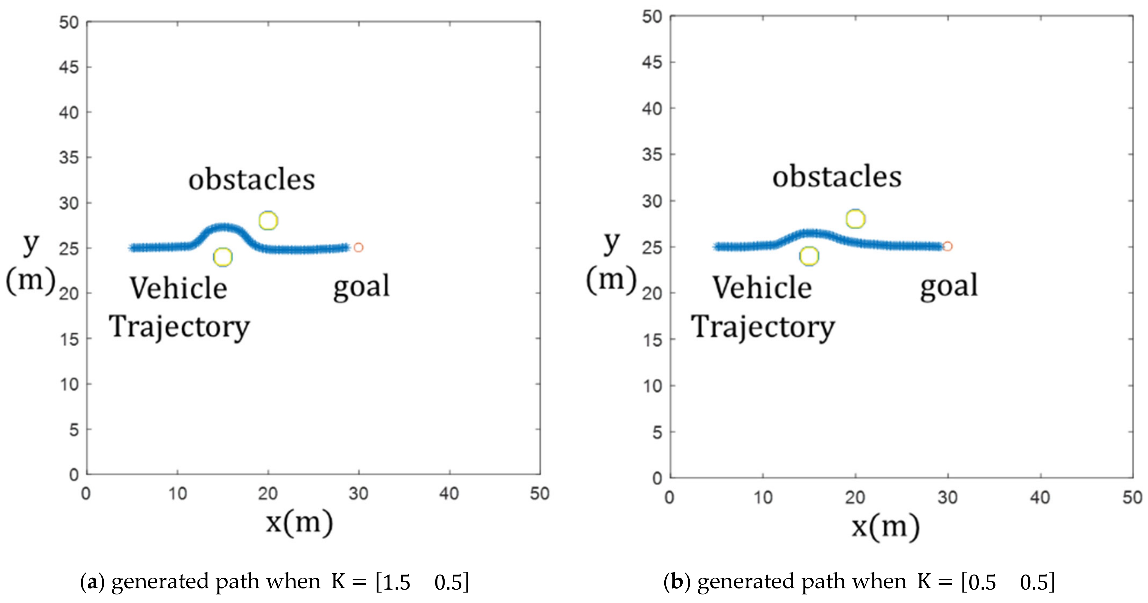
Five sets of W were defined using W r = 1.5 0.2 r ,   0.5 ,   0 , each with different w s values. The generated paths are illustrated in the Figure 7, where K = k 1 k 2 in Equation (11) is defined as K = 1.5 0.5 and K = 0.5 0.5 .
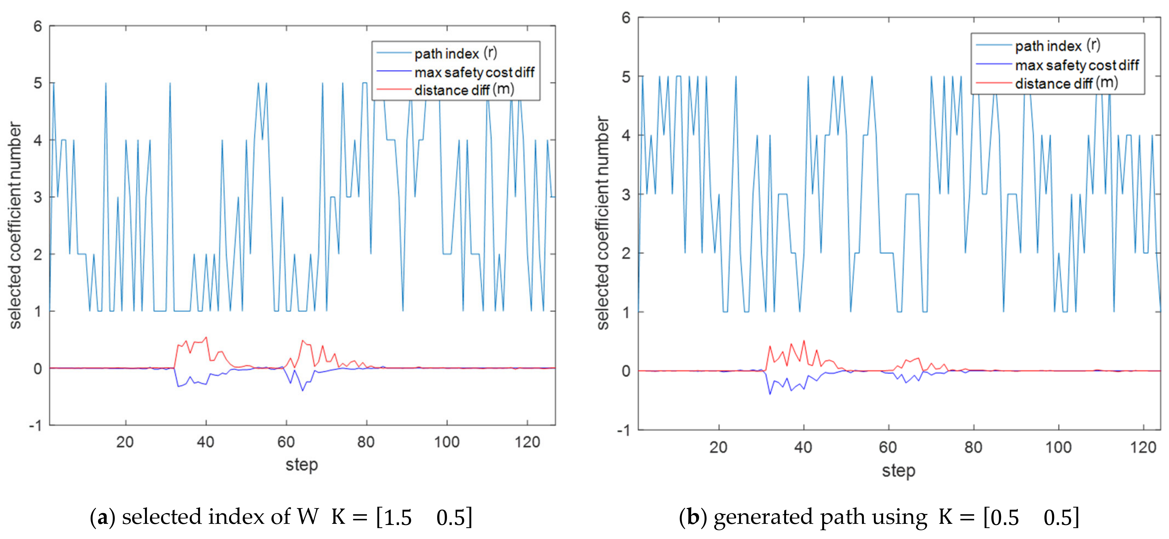
The figure below shows the r values of the final selected Wr, and the difference in M a x U | g B r and D g o a l g B r , when r = 1 and r = 5 at each step until the vehicle reaches its destination.
In the Figure 8, variations occur in the values of M a x U | g B r and D g o a l g B r when encountering the first and second obstacles, and the coefficient K begins to influence the path selection. In case (a), a long-distance route is chosen for safety when encountering an obstacle. Once the obstacle has been passed, the shortest route to the destination is chosen. In case (b), although a safer path is selected when an obstacle is encountered, there is a higher tendency to choose the shortest path to the global path.
This simulation was performed on a PC equipped with an Intel® Core™ i7-8559U CPU @ 2.7 GHz and 16 GB RAM. 124 time steps were calculated before the vehicle reached its destination. The constants related to MPC that have a significant impact on computation time were set as follows: T = 3, dt = 0.2, N = 40, and M = 30. After calculating the average time taken, it was found that one time step took approximately 33 ms.
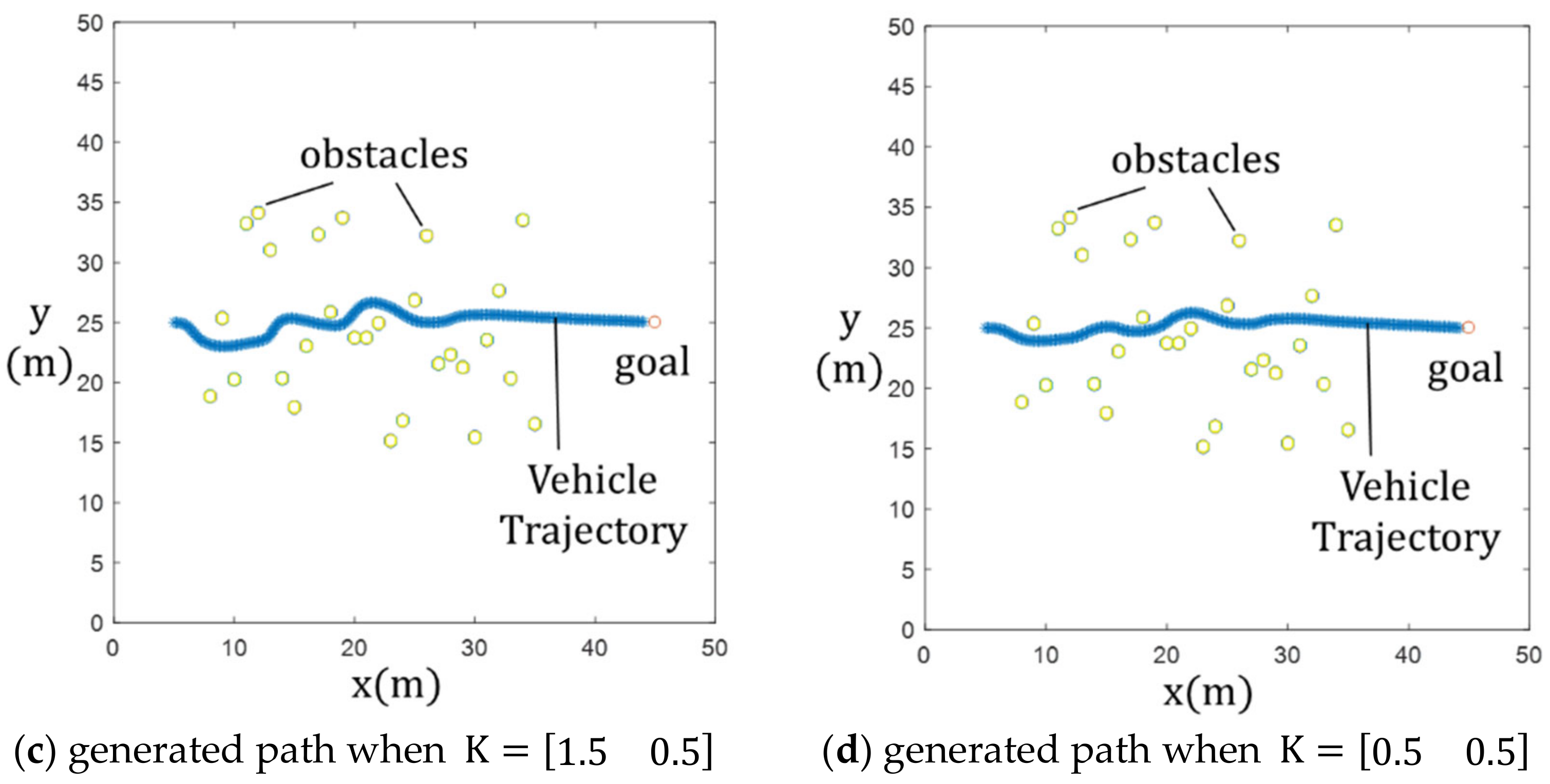
When driving with only one set of W in an area with complex obstacles, the vehicle may excessively avoid obstacles, as shown in (a) of Figure 9, or avoidance may occur due to it being too close to obstacles, even in non-dense areas, as shown in (b). However, by defining five sets of W and creating paths through adjusting the constant K, it is possible to avoid obstacles that are far away in less dense areas, as shown in (c) and (d). Additionally, it is possible to achieve a close avoidance of obstacles in dense areas during path generation.

4. Experiment

A steering-type vehicle was equipped with an RTK GPS for localization, LiDAR for obstacle recognition, and NVIDIA’s Jetson AGX Xavier for executing driving control. The appearance of the vehicle is as shown in Figure 10.
Using LiDAR, the point cloud information of the surrounding obstacles was acquired. Subsequently, a 2D grid map was generated from that point cloud information, and a grid map with a calculated potential field was obtained as shown in Figure 11. After that, a global path was created, in a straight line, to the destination, and a local path was generated using the MPC-PF-PSO algorithm.
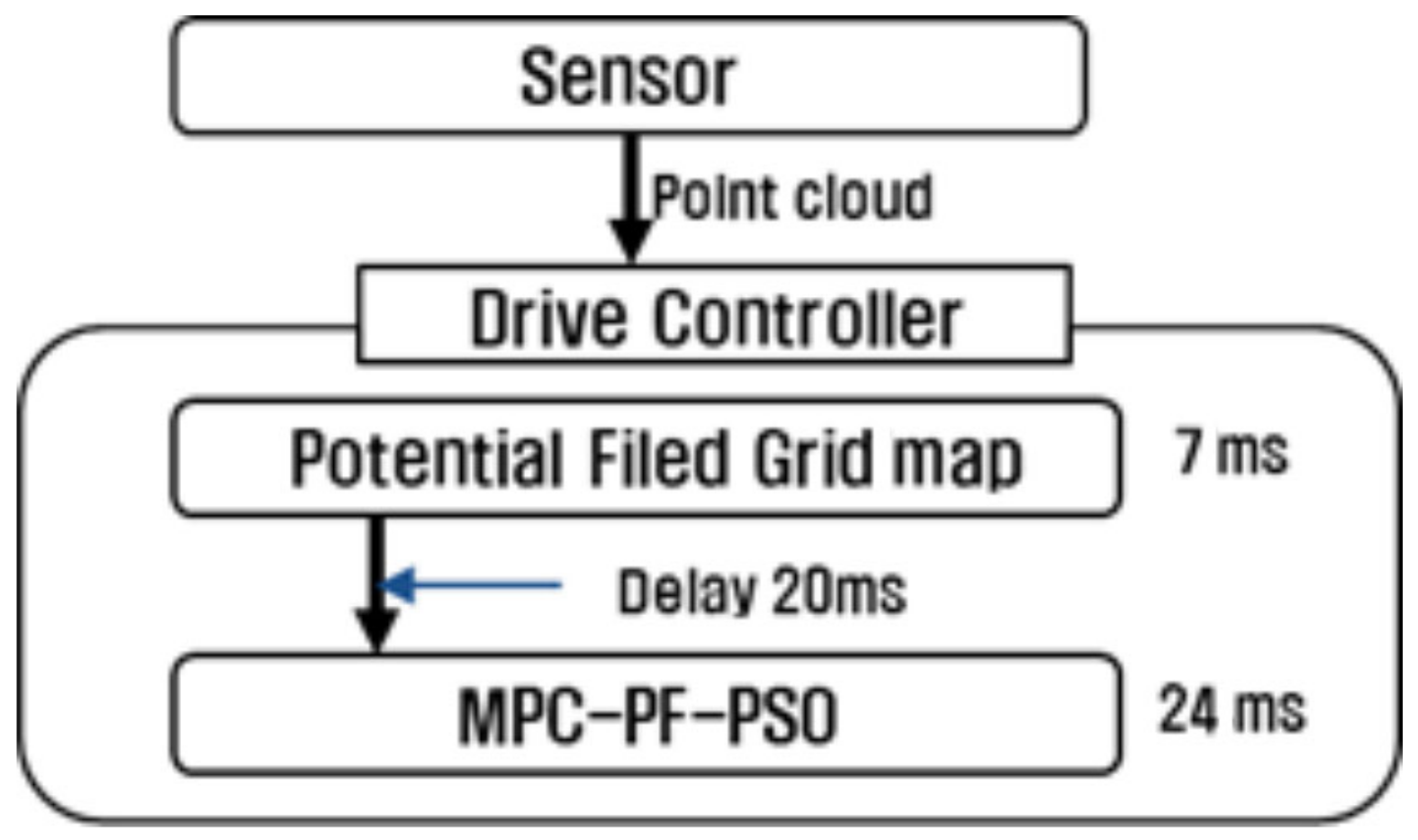
Computation time is a crucial factor in obstacle avoidance during navigation. We have implemented the MPC-PF-PSO algorithm and a package that computes the potential field of an obstacle point cloud in an ROS Melodic environment. We measured the computation time used by each package.
The MPC-PF-PSO-related constants were defined as T = 3, dt = 0.2, N = 40, M = 30, and 5 sets of W. It took 7 ms to generate a 2D grid map containing potential field information, and the MPC-PF-PSO algorithm’s operation took 24 ms as shown in Figure 12.
A driving experiment was performed by applying the MPC-PF-PSO algorithm. Obstacles were placed, using bricks, and a global path was established in a straight line to the destination point as shown in Figure 13. Experiments were conducted by altering the constant K. When the coefficient k 1   (for the maximum potential M a x U | g B r ) was relatively larger than the coefficient k 2   (for the distance to the destination D g o a l g B r ), a path was generated that avoided the obstacle further, as confirmed in the simulation.
The driving vehicle and data visualization for the cases of K = [0.5 0.5] and K = [1.5 0.5] are shown in Figure 14. We measured the distance using log data to see how far the vehicle traveled from the obstacle, and the results are shown in the Figure 15. For K = [0.5, 0.5] and K = [1.5, 0.5], the shortest distances between the obstacle and the global path were 0.44 m and 0.62 m, respectively. The shortest distances between the obstacle and the vehicle were 1.03 m and 1.25 m, respectively. For K = [0.5, 0.5], even though a distance from the global path to the obstacle were closer than that of K = [1.5, 0.5], the vehicle drove closer to the obstacle.

5. Discussion

In this paper, our focus was on developing an algorithm that can be applied in practical scenarios, not only for obstacle avoidance but also for real-time decision making to ensure safe navigation. We applied a potential field to assess safety, used MPC to consider the characteristics of the actual moving vehicle, and employed the PSO algorithm to ensure real-time responsiveness. Additionally, we introduced a method for utilizing various coefficient sets to determine whether to select a safe path or a fast path according to the surrounding environment. The algorithm was implemented through ROS on Jetson Xavier, which was released by NVIDIA. Through computational time measurements and experiments, we demonstrated that this algorithm is suitable for practical use.
While the proposed method is suitable for real-time applications, a challenge lies in the low consistency of its path generation, attributed to the utilization of randomness at each step of finding the optimal path. Future research will focus on enhancing path consistency, considerations for dynamic obstacles, and developing path generation methods for irregular terrains.

Author Contributions

Conceptualization and methodology: M.K. and M.L.; formal analysis and software: M.K. and B.K.; data curation, writing—original draft, and writing—review and editing: M.K.; validation: M.L. and M.C.; supervision, project administration, and funding acquisition: M.C. All authors have read and agreed to the published version of the manuscript.

Funding

This research was supported by the Basic Research Project of KIMM (No. NK242I), the National Research Foundation of Korea (NRF) through a grant funded by the Korean government (MSIT) (No. 2020M3C1C1A02086421), and the National Research Council of Science & Technology (NST) grant by the Korea government (MSIT) (No. CRC23041-400).

Data Availability Statement

Data are contained within the article.

Conflicts of Interest

The authors declare no conflicts of interest.

References

  1. González, D.; Pérez, J.; Milanés, V.; Nashashibi, F. A review of motion planning techniques for automated vehicles. IEEE Trans. Intell. Transp. Syst. 2015, 17, 1135–1145. [Google Scholar] [CrossRef]
  2. Lavalle, S.M. Planning Algorithms; Cambridge University Press: New York, NY, USA, 2006. [Google Scholar]
  3. Dijkstra, E.W. A note on two problems in connexion with graphs. Numer. Math. 1959, 1, 269–271. [Google Scholar] [CrossRef]
  4. Hart, P.E.; Nilsson, N.J.; Raphael, B. A formal basis for the heuristic determination of minimum cost paths. IEEE Trans. Syst. Sci. Cybern. 1968, 4, 100–107. [Google Scholar] [CrossRef]
  5. Elbanhawi, M.; Simic, M. Sampling-based robot motion planning: A review. IEEE Access 2014, 2, 56–77. [Google Scholar] [CrossRef]
  6. Kavraki, L.E.; Svestka, P.; Latombe, J.-C.; Overmars, M.H. Probabilistic roadmaps for path planning in high-dimensional configuration spaces. IEEE Trans. Robot. Autom. 1996, 12, 566–580. [Google Scholar] [CrossRef]
  7. LaValle, S.M.; Kuffner, J.J. Randomized kinodynamic planning. Int. J. Robot. Res. 2001, 20, 378–400. [Google Scholar] [CrossRef]
  8. Brezak, M.; Petrovic, I. Real-time approximation of clothoids with bounded error for path planning applications. IEEE Trans. Robot. 2014, 30, 507–515. [Google Scholar] [CrossRef]
  9. Koren, Y.; Borenstein, J. Potential field methods and their inherent limitations for mobile robot navigation. In Proceedings of the 1991 IEEE International Conference on Robotics and Automation, Sacramento, CA, USA, 9–11 April 1991. [Google Scholar]
  10. Kim, K. Predicted Potential Risk-Based Vehicle Motion Control of Automated Vehicles for Integrated Risk Management. Ph.D. Thesis, Seoul National University, Seoul, Republic of Korea, 2016. [Google Scholar]
  11. Kim, J.; Pae, D.; Lim, M. Obstacle Avoidance Path Planning based on Output Constrained Model Predictive Control. Int. J. Control Autom. Syst. 2019, 17, 2850–2861. [Google Scholar] [CrossRef]
  12. Mac, T.T.; Copot, C.; Tran, D.T.; De Keyser, R. Heuristic approaches in robot path planning: A survey. Robot. Auton. Syst. 2016, 86, 13–28. [Google Scholar] [CrossRef]
  13. Sfeir, J.; Saad, M.; Hassane, H.S. An improved artificial potential field approach to real-time mobile robot path planning in an unknown environment. In Proceedings of the 2011 IEEE International Symposium on Robotic and Sensors Environments (ROSE), Montreal, QC, Canada, 17–18 September 2011. [Google Scholar]
  14. Kim, D.H. Escaping route method for a trap situation in local path planning. Int. J. Control Autom. Syst. 2009, 7, 495–500. [Google Scholar] [CrossRef]
  15. Kim, D.H.; Shin, S. Local path planning using a new artificial potential function configuration and its analytical design guidelines. Adv. Robot. 2006, 20, 115–135. [Google Scholar] [CrossRef]
  16. Zuo, Z.; Yang, X.; Wang, Y.; Han, Q.; Wang, L.; Luo, X. MPC-based cooperative control strategy of path planning and trajectory tracking for intelligent vehicles. IEEE Trans. Intell. Veh. 2020, 6, 513–522. [Google Scholar] [CrossRef]
  17. Ji, J.; Khajepour, A.; Melek, W.W.; Huang, Y. Path planning and tracking for vehicle collision avoidance based on model predictive control with multiconstraints. IEEE Trans. Veh. Technol. 2016, 66, 952–964. [Google Scholar] [CrossRef]
  18. Huang, Z.; Wu, Q.; Ma, J.; Fan, S. An APF and MPC combined collaborative driving controller using vehicular communication technologies. Chaos Solitons Fractals 2016, 89, 232–242. [Google Scholar] [CrossRef]
  19. Du, X.; Htet, K.K.K.; Tan, K.K. Development of a genetic-algorithm-based nonlinear model predictive control scheme on velocity and steering of autonomous vehicles. IEEE Trans. Ind. Electron. 2016, 63, 6970–6977. [Google Scholar] [CrossRef]
  20. Van Heerden, K.; Fujimoto, Y.; Kawamura, A. A combination of particle swarm optimization and model predictive control on graphics hardware for real-time trajectory planning of the under-actuated nonlinear acrobot. In Proceedings of the 2014 IEEE 13th International Workshop on Advanced Motion Control (AMC), Yokohama, Japan, 14–16 March 2014. [Google Scholar]
  21. Thomas, J. Particle swarm optimization based model predictive control for constrained nonlinear systems. In Proceedings of the 2014 11th International Conference on Informatics in Control, Automation and Robotics (ICINCO), Vienna, Austria, 2–4 September 2014. [Google Scholar]
  22. Zuo, Z.; Dai, L.; Wang, Y.; Yang, X. Fast nonlinear model predictive control parallel design using QPSO and its applications on trajectory tracking of autonomous vehicles. In Proceedings of the 2018 13th World Congress on Intelligent Control and Automation (WCICA), Changsha, China, 4–8 July 2018. [Google Scholar]
  23. Khatib, O. Real-time obstacle avoidance for manipulators and mobile robots. Int. J. Robot. Res. 1986, 5, 90–98. [Google Scholar] [CrossRef]
  24. Kim, M.; Yoo, S.; Lee, D.; Lee, G. Local path-planning simulation and driving test of electric unmanned ground vehicles for cooperative mission with unmanned aerial vehicles. Appl. Sci. 2022, 12, 2326. [Google Scholar] [CrossRef]
  25. Choset, H. Robotic Motion Planning: Potential Functions; Robotics Institute, Carnegie Mellon University: Pittsburgh, PA, USA, 2010. [Google Scholar]
  26. Shin, J.; Kwak, D.; Kwak, K. Model predictive path planning for an autonomous ground vehicle in rough terrain. Int. J. Control Autom. Syst. 2021, 19, 2224–2237. [Google Scholar] [CrossRef]
  27. LI, X.; Wu, D.; He, J.; Bashir, M.; Liping, M. An improved method of particle swarm optimization for path planning of mobile robot. J. Control Sci. Eng. 2020, 2020, 3857894. [Google Scholar] [CrossRef]
Figure 1. Modeling for steering-type vehicle.
Robotics 13 00046 g001
Figure 2. Potential field graph.
Robotics 13 00046 g002
Figure 3. Path change according to number of iterations performed.
Robotics 13 00046 g003
Figure 4. Path generation for obstacle avoidance.
Robotics 13 00046 g004
Figure 5. Generated paths, according to the coefficient W, for one obstacle.
Robotics 13 00046 g005
Figure 6. Generated paths, according to the coefficient W, for two obstacles.
Robotics 13 00046 g006
Figure 7. Generated paths, according to the coefficient K, for two obstacles.
Robotics 13 00046 g007
Figure 8. Graphs of selected coefficient index r and difference between M a x U | g B r and D g o a l g B r .
Robotics 13 00046 g008
Figure 9. Generated paths in a multiple-obstacle area.
Robotics 13 00046 g009aRobotics 13 00046 g009b
Figure 10. Vehicle for driving experiment.
Robotics 13 00046 g010
Figure 11. From point cloud to potential field grid map.
Robotics 13 00046 g011
Figure 12. Computation times for each package.
Robotics 13 00046 g012
Figure 13. Visualized data during obstacle avoidance experiments.
Robotics 13 00046 g013
Figure 14. Obstacle avoidance experiments with different K coefficients.
Robotics 13 00046 g014
Figure 15. Results of obstacle avoidance experiments.
Robotics 13 00046 g015
Table 1. Simulation variables.
Variables
γ Inertia of V i j in PSO
c 1 Weight of particle best in PSO
c 2 Weight of global best in PSO
w s Weight of safety in cost function
w d Weight of distance from global path in cost function
w u Weight of input in cost function
Disclaimer/Publisher’s Note: The statements, opinions and data contained in all publications are solely those of the individual author(s) and contributor(s) and not of MDPI and/or the editor(s). MDPI and/or the editor(s) disclaim responsibility for any injury to people or property resulting from any ideas, methods, instructions or products referred to in the content.