Abstract
This article describes an apparatus developed by the authors as a substitution for physical therapists regarding mechanical movements in the rehabilitation of frozen shoulder. In particular, the performance of this apparatus is improved in comparison with existing methods in terms of the following two major points: (1) realization of individual rehabilitation for the patient’s scapula by an innovative parallel–serial hybrid linkage design and supporting parts that can fix and move the patient’s scapula; and (2) the addition of a “teaching” and “playback” mode to enable the apparatus to record the motion of rehabilitation, allowing it to be customized for each patient by physical therapists and reproduce the recorded motion accurately, thus freeing physical therapists from repetitive rehabilitation routines. With the introduction of the whole system, experimental results are shown and discussed to verify and evaluate the performance of the developed apparatus.
1. Introduction
Frozen shoulder, also known as “adhesive capsulitis” or “periarthritis of the shoulder”, is a syndrome that causes shoulder pain and limitation of the upper extremity range of motion (ROM). Generally, its progression can be divided into three stages: (1) a freezing stage that lasts for 2–9 months, with onset of pain and loss of motion in the shoulder; (2) a frozen stage that lasts for 4–12 months, with slow relief of pain and continuation of stiffness; (3) a thawing stage that lasts for 5–26 months, with eventual slow recovery of shoulder motion (the duration of each stage varies in different reports) [1].
Depending on the stage of disease, the treatment of frozen shoulder involves a combination of therapies such as medication, local steroid injection, and physical therapy [2]. In comparison with conventional types of physical therapy, Continuous Passive Motion (CPM) therapy has shown advantages in pain reduction [3], making it not only effective for the shoulder but also for the knee, hip, and elbow. In this therapy, the physical therapist holds the patient’s upper arm and performs repetitive movements of the upper arm and shoulder within the patient’s joint ROM. This therapy is performed by one physical therapist and may last for one hour each time (at least once a week is recommended); this procedure is repeated until the patient’s ROM is expanded and recovered.
However, it is not difficult to imagine the heavy workload and fatigue for physical therapists during the months (or even years) of repeating CPM therapy. Therefore, CPM machines have emerged as partial substitutes for physical therapists in terms of performing CPM. Since 1978 [4], CPM machines have been significantly improved in terms of their mechanical design, functionality, and safety, with their effectiveness having been verified mainly for postoperative pain management [5]. Consequently, CPM machines have been sold on the market for decades and have contributed to the faster recovery of patients.
Nevertheless, the CPM machines developed and sold on the market [6,7,8,9,10] so far cannot completely replace the role of physical therapists and perform customized CPM for a patient according to their individual features. Specifically, the following two issues still require further improvements or even solutions: (a) no independent motion training is available for the scapula (the bone of the shoulder blade); and (b) the CPM machines currently on the market cannot exactly reproduce the arbitrary training motion performed by a physical therapist.
Regarding (a), since frozen shoulder is a syndrome that involves the shoulder complex (its brief anatomical analysis will be shown in the next section), which includes not only the shoulder joint but also the scapula, limitation of ROM due to the pain may occur for both of these regions. However, currently available CPM machines only allow training of the shoulder joint, while training of the scapula, especially for independent training, is not available. Take the CPM machines “Kinetec Centura™” [6] and “ARTROMOT®-S4” [8] as examples; there is no movable mechanical part or structural support available to fix the patient’s scapula, which means that training of the scapula by moving it with the motor torque of the machine is not possible. Apparently, an apparatus that can hold and control the motion of the patient’s scapula is necessary for the complete training effect of CPM therapy against frozen shoulder.
Regarding (b), CPM machines currently on the market are capable of performing pre-programmed CPM motion, though this may not be completely identical to the CPM motion by physical therapists customized for each individual patient, which is also different from one patient to another. Take Kinetec Centura™ as an example again; only the following four motion patterns are available: (1) abduction/adduction; (2) extension/flexion; (3) external/internal rotation; and (4) synchronized abduction and rotation [11]. However, any one of these motion patterns alone is not sufficient to adapt to the individual differences of each patient, let alone to the training motion for the scapula. Consequently, pre-programmed CPM motion by these CPM machines may not be exactly suitable for each patient, and thus, an apparatus capable of reproducing the same CPM motion by a professional physical therapist is indispensable for the complete training effect of CPM against frozen shoulder. Here, the function of teaching and playback mode for industrial robots was chosen as a reference. In teaching mode, an industrial robot records the motion “taught” by a human, which is performed by moving the robot manually, and in playback mode the robot performs the identical motion. Inspired by this idea, a rehabilitation apparatus with the function of teaching and playback became one of the objectives in this research. In teaching mode, the apparatus records the CPM motion by a physical therapist, and in playback mode, the robot reproduces the same CPM motion.
Consequently, a rehabilitation apparatus for frozen shoulder that improves and solves the issues (a) and (b) described above was developed by the authors and is introduced in this article. The introduction of its former version can be seen in the authors’ previous works [12,13].
The remainder of this article is organized as follows. In Section 2, preliminary knowledge is given, which is necessary for the understanding of this article from both anatomical and engineering perspectives. First, the biomechanics of the shoulder complex, where frozen shoulder takes place, is illustrated and explained. Subsequently, an overview of the apparatus is given, including its specifications and main features. With prerequisite knowledge introduced, Section 3 further introduces the details of the apparatus, including its mechanical design and a kinematics analysis. In Section 4, experiment results regarding (1) joint ROM for each Degree of Freedom (DoF) and (2) reproducibility of CPM in playback mode in comparison with teaching mode are presented for both the left and right shoulders of healthy subjects to evaluate the performance of the apparatus, along with a discussion. Finally, Section 5 concludes the article and presents future works.
2. Preliminary Knowledge
2.1. Biomechancis of Shoulder Complex
The biomechanics of the shoulder complex has been revealed and thoroughly studied in the literature [14,15,16,17]. Thus, in this subsection, only basic information is shown, which is indispensable for the comprehension of the following contents, especially regarding the joint structure of the developed apparatus.
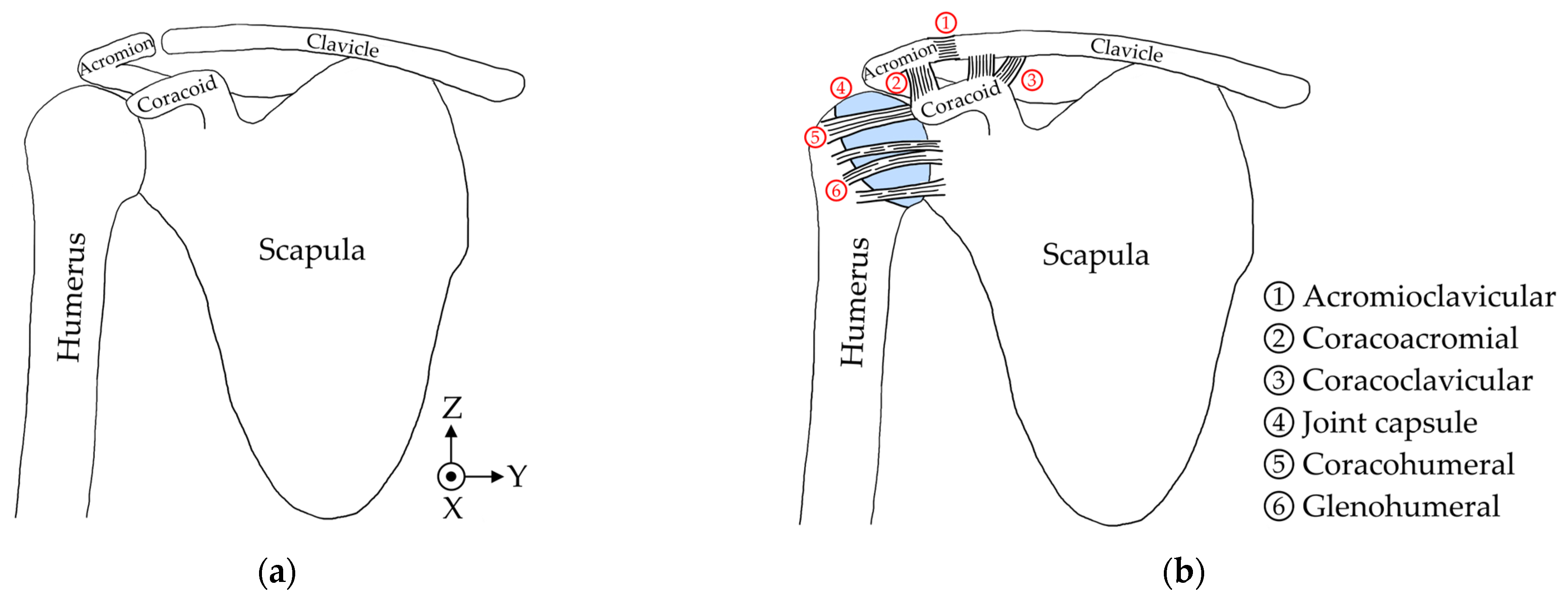
To begin, the anatomical illustration of a human’s shoulder complex is shown in Figure 1. Ligaments, muscles, and shoulder articular cartilage are omitted in Figure 1a for a clearer view of bone structures. It consists of three main parts, which are the clavicle (collarbone), scapula (shoulder blade), and humerus (arm bone). The acromion and coracoid are two components of scapula, and the former forms a closed circle with the clavicle while the latter connects with both the acromion and clavicle via ligaments, which are depicted in Figure 1b with all ligaments and their names shown. The humerus and scapula form a ball-socket structure in the shoulder joint with the lubrication of synovial fluid inside the joint capsule, making the shoulder joint behave like a 3-DoF ball joint. Meanwhile, as the parent link of the humerus, the scapula itself also has its own ROM. It can rotate about the X-axis and Z-axis, shown in Figure 1a, to move the shoulder joint upward/downward or forward/backward.
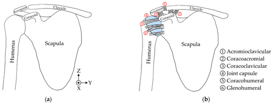
Figure 1.
Illustrations of the human shoulder complex: (a) with only bones; (b) with bones, ligaments, and articular cartilage (joint capsule) marked in blue.
Figure 2 lists the basic motions of the whole shoulder complex with reference ROM. An arbitrary motion of the shoulder complex can be performed by one or a combination of multiple motions shown in Figure 2. The motions of No. 1 and No. 2 are the rotation motion of scapula described earlier, while the motions of Nos. 3–6 are the motions of the shoulder joint, where No. 3 and No. 5 are the rotation motions of shoulder joint and No. 4 is the twisting motion of shoulder joint. Note that the motions of shoulder joint may be accompanied with motion(s) of the scapula, but not vice versa.
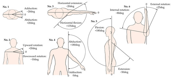
Figure 2.
Reference value of ROM for six basic motions of shoulder complex. No. 1 and No. 2 are motions of the scapula, and Nos. 3–6 are motions of the shoulder joint.
Regarding the motion of No. 6, there are three different types of position that may cause confusion: in the 1st position, the upper arm drops down naturally along the −Z-axis; in the 2nd position, the upper arm is lifted horizontally along the −Y-axis; and in the 3rd position, the upper arm is lifted horizontally and extended forward along the +X-axis. The ROM for these three positions differs from each other. In this article, the 3rd position was chosen for two reasons: (a) the authors are told that 2nd and 3rd positions are mainly adopted in current rehabilitation praxes by physical therapists instead of the 1st position, which is frequently seen in research papers; (b) the ROM of the 3rd position is wider in external rotation (around 20–30 deg) than that of the 2nd position (around 10 deg), which is easier to observe and also safer to implement on the developed apparatus.
2.2. Introduction of the Developed Apparatus
The apparatus introduced in this article was developed by Terada Laboratory, University of Yamanashi, Japan. It was designed and developed for the rehabilitation of frozen shoulder, aiming to provide CPM therapy for the shoulder complex of patients on both the left and right sides with high accuracy and usability for physical therapists. It has five DoFs and is fixed on the pole of an upper limb training device (with the shoulder pulley removed) with a height-adjustable chair as the base frame.
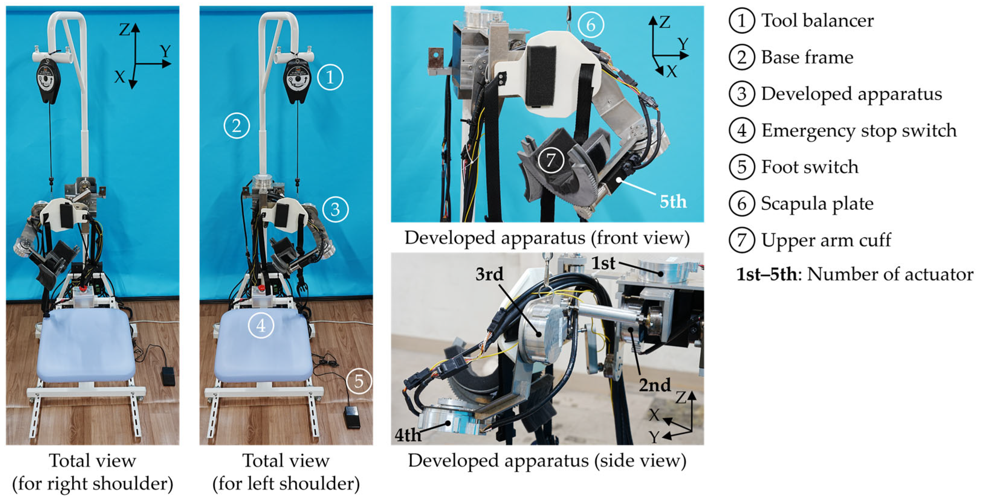
An overview of the apparatus, along with its base and all other parts, can be seen in Figure 3. The size of the entire device is 768(D) × 600(W) × 1440(H) (height adjustable, up to 2035 mm) and the weight of mechanical parts of the apparatus is 8.3 kg. The material of major structural parts in the apparatus is A5052, a type of aluminum alloy.
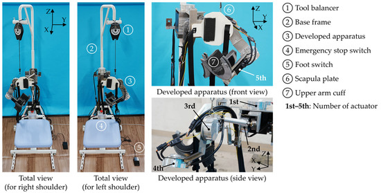
Figure 3.
Overview of the entire rehabilitation device and the developed apparatus.
Five electric motors are used, where the 1st (abduction/adduction) and 2nd (upward/downward rotation) motors are for the motion of scapula, the 3rd (abduction/adduction) and 4th (flexion/extension or horizontal extension/flexion) for the shoulder joint, and the 5th for external/internal rotation of the shoulder joint. Note that three motions of the shoulder joint are realized by only two motors, because the link design enables the motor controlling the rotation about Y-axis in shoulder joint (4th motor) to switch its rotation to the Z-axis when the arm is lifted horizontally, enabling horizontal extension/flexion. Three 240 W power supply units are used to drive the 1st and 2nd, the 3rd and 4th, and the 5th motors, respectively.
Just as shown in the left half of Figure 3, the whole apparatus can be rotated about the X-axis by 180 deg so that it can be applied to both the left and right shoulder of a patient. The whole process of left–right switch only involves pulling out and inserting a pin and the rotation of the apparatus. The detailed mechanism for left–right switching is described in detail in [12,13] and is thus omitted here. Different from existing CPM machines with serial links, parallel links and ball joints are applied for the motions of scapula. For the scapula and upper arm, where direct contact between the apparatus and patient occurs, a supporting plate (white) and a surrounding cuff (grey) made of nylon are added, respectively, so that they can fix the corresponding parts of the human body to the apparatus with the help of an adjustable side release buckle belt and urethane foams. A tool balancer hangs the apparatus from above to maintain its posture when it is powered off.
Safety measures for patients were prepared in multiple ways according to the suggestions from the physical therapists: (1) A foot switch was added so that a physical therapist can hold the patient’s arm with both hands while manipulating the switch with one foot. In teaching mode, training motion will only be recorded when the foot switch is being stepped on; (2) An emergency stop switch was added so that in playback mode, when there is motor torque transmitted to the patient, the patient can push the switch and stop the apparatus at any time. Even if the emergency stop switch fails, the operator of apparatus can also shut down the power supply units at any time; (3) Rated torque of all motors is low enough so that the motors lose their torque when the patient tries to fight against their torque, which contributes the prevention of injuries.
Table 1 summarizes the details of all components mentioned above, with their manufacturer, model name, and main specifications listed for reference.

Table 1.
Details of the main components in the developed apparatus.
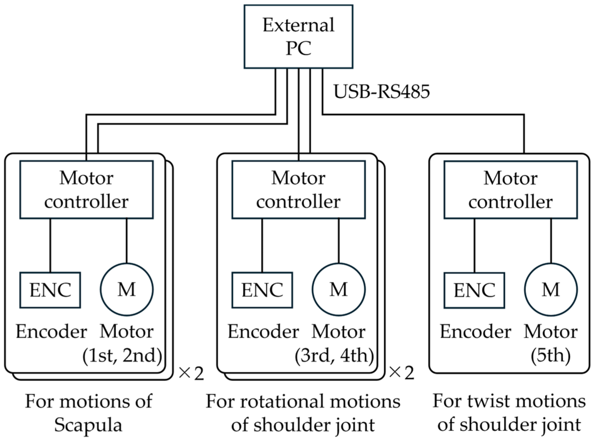
The apparatus receives control commands from an external PC via RS485 serial communication. Its system configuration is depicted in Figure 4. The motor angles are sampled in teaching mode and output in playback mode at 10 Hz. Its control software is written in Python 3.11.0 and runs on an external PC, as shown in Figure 4. All five motors are position-controlled with PID control, and all control parameters have been tuned in advance.
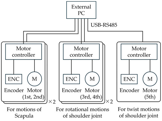
Figure 4.
System configuration of the developed apparatus.
3. Design and Analysis of the Developed Apparatus
3.1. Mechanical Design
The mechanical parts of the apparatus in this article can be divided into two major parts: (1) parts for the scapula (parallel links); and (2) parts for the shoulder joint (serial links), including parts for the external/internal rotation of the shoulder joint. Together, they form a parallel–serial hybrid link mechanism.
3.1.1. Parts for Scapula (Parallel Links)
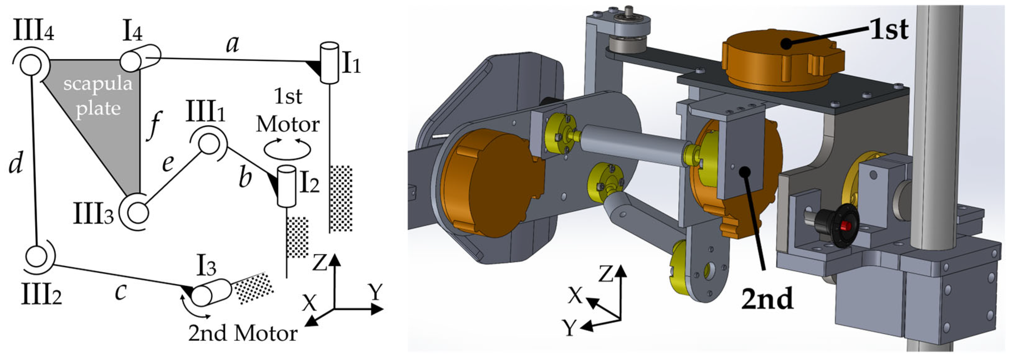
The ROM of scapula illustrated in Figure 2 has shown that scapula rotates about the X-axis and Z-axis. Therefore, the scapula plate mentioned in Figure 3 is fixed on a board that can rotate about the X-axis and Z-axis, and the board is connected to two motors (1st and 2nd motor) via four links (b, c, d, e) and four passive ball joints (III1, III2, III3, III4), which are 3D parallel links as a whole. Details can be seen in Figure 5.

Figure 5.
Parallel link model for scapula and corresponding mechanical parts in CAD.
The reasons for choosing parallel links instead of serial links for the scapula are as follows: (a) much smaller ROM is required in comparison with shoulder joint; and (b) due to limitations of space and layout. Regarding (a), it is widely known that parallel links have smaller workspaces than serial links, yet fortunately, the ROM for the scapula is also much smaller (−10 deg–+20 deg for upward/downward rotation and −20 deg–+20 deg for abduction/adduction), making parallel links a feasible option. Regarding (b), serial links have been used in CPM machines in the past, which only deals with the training for the shoulder joint instead of the shoulder complex. However, taking the scapula into consideration, serial links would be too large (especially in depth) to fit the narrow and flat space behind the back of the human body, inevitably passing over the head of patient as well. Meanwhile, cantilever serial links have higher requirements in terms of rigidity than parallel links, which would result in a much larger and heavier mechanical structure in the case of the scapula.
3.1.2. Parts for the Shoulder Joint (Serial Links)
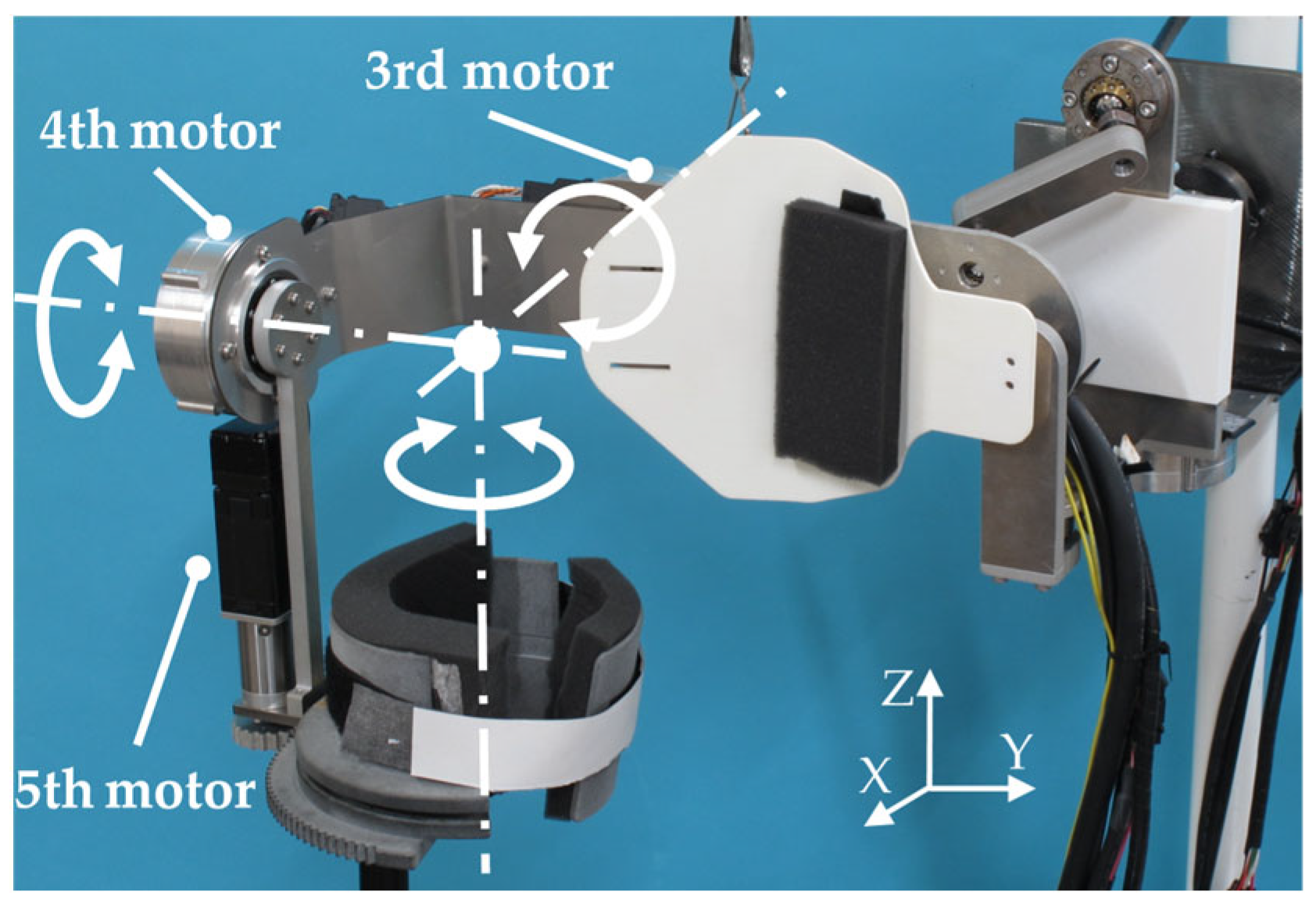
As mentioned in Section 2.1, the shoulder joint can be considered as a 3-DoF ball joint. To reproduce this feature to the greatest extent possible, the serial links depicted in Figure 6 were developed for the shoulder joint, with annotations for the motors, rotation axes, and directions shown in the figure. Note that all three rotation axes intersect in one single point through the appropriate design of links and an upper arm cuff that will be introduced later in this paper.

Figure 6.
Serial links for the shoulder joint with annotations for the motors, rotation axes, and directions.
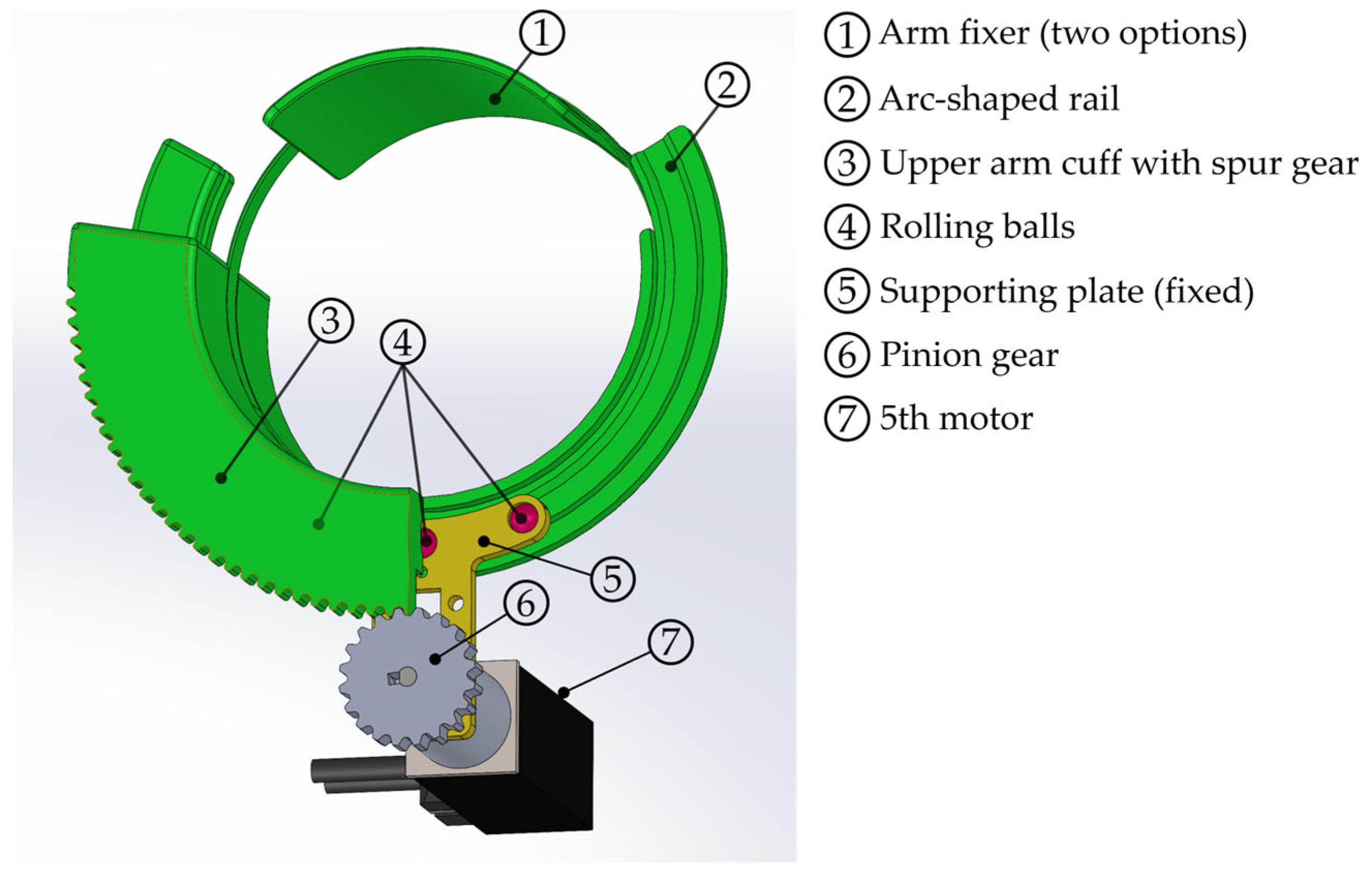
Regarding the twisting motions of the shoulder joint, which are external/internal rotations, a pinion-spur gear mechanism was adopted. Details of the mechanisms of this part were illustrated in CAD 2023 (24.2.53.0) and are shown in Figure 7.

Figure 7.
Mechanisms for external/internal rotation of shoulder joint.
The green parts in Figure 7 form a circle, including an arm fixer and upper arm cuff with spur gear that are connected via Velcro belts and can be rotated. These are used to hold the patient’s upper arm. The arm fixer is detachable, while the upper arm cuff with spur gear is a C-shaped part that meshes with the pinion gear attached to the 5th motor. Inside the upper arm cuff, there is a supporting plate fixed to the 5th motor with three rolling balls that can roll along arc-shaped rail carved in the upper arm cuff. This design helps achieve a smooth and stable rotation of the upper arm cuff.
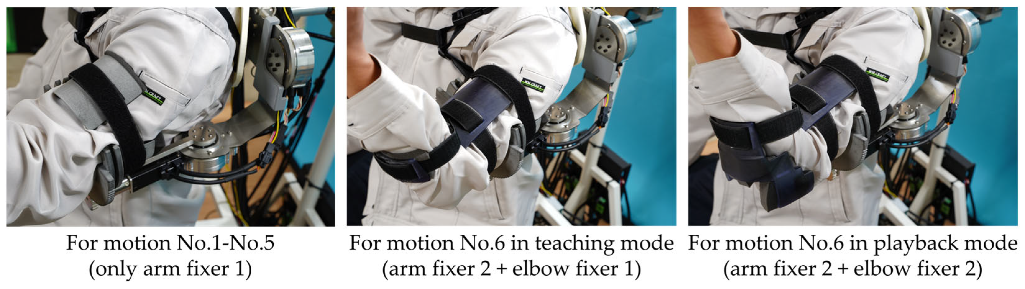
As mentioned in Figure 7, there are two options for the arm fixer. The one illustrated in Figure 7 is made of nylon and is used for motion Nos. 1–5, while the other one is used exclusively for motion No. 6 (external/internal rotation of the shoulder joint). It enhances torque transfer efficiency in comparison with its former version [12,13], in combination with a new part called the “elbow fixer”, thanks to a longer torque arm. For the elbow fixer, there are also two options for teaching mode and playback mode. These parts are all 3D-printed in resin, and their CAD is depicted in Figure 8.
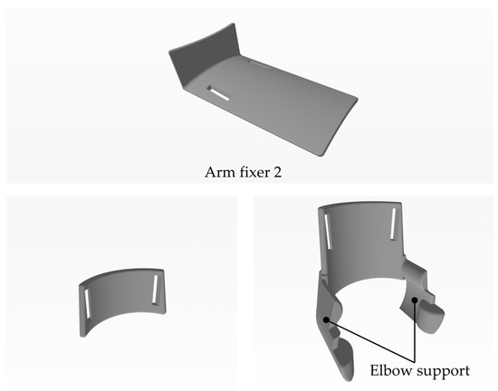
Figure 8.
CAD of arm fixer 2 and two elbow fixers for external/internal rotation of the shoulder joint.
In all three parts, there are two holes so that a belt with Velcro can go through them. Unlike elbow fixer 2, there are no supporting parts for the elbow in elbow fixer 1, because in teaching mode, a physical therapist may need to hold the patient’s elbow, while in playback mode, the supporting parts of elbow fixer 2 contribute to better torque transfer. Figure 9 shows three cases with different combinations of arm fixers and elbow fixers.

Figure 9.
Combinations of arm fixer and elbow fixer in different cases.
3.2. Kinematic Analysis
As mentioned in Section 3.1.1, 3D parallel links are adopted for the motion of the scapula, which is rather unique in comparison with common serial link design for the shoulder joint. Therefore, the kinematics of these 3D parallel links is given in this section.
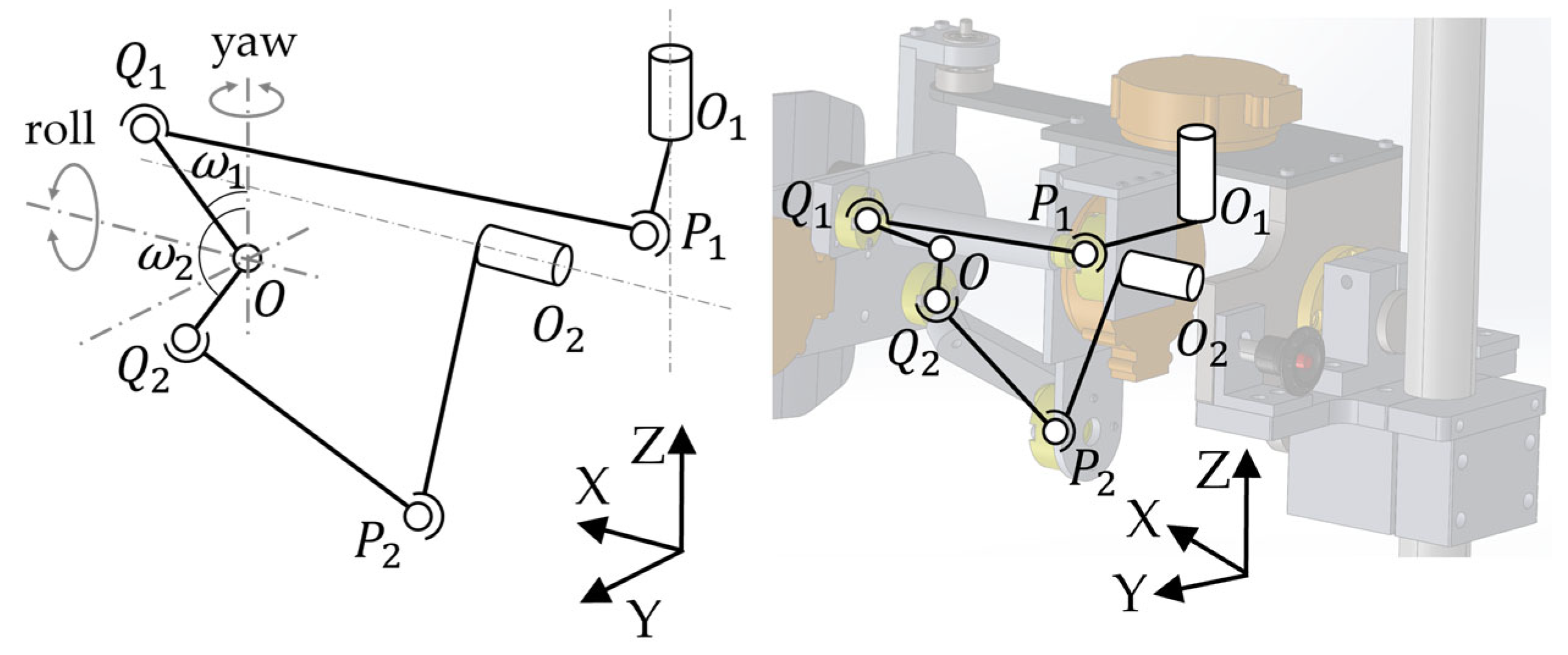
The geometric link model and its corresponding link mechanism shown in CAD are illustrated in Figure 10. Point O is defined as the origin. The scapula board, where the scapula plate is attached, can be rotated about the X-axis and Z-axis as the left half of Figure 10 shows, and these two axes intersect at O, a point on the scapula board that remains unmoved in space, just like O1 and O2. P1, P2, Q1, and Q2 all denote ball joints. Q1 and Q2 are fixed to the scapula board. The segment P1O1 is parallel to XO2Y plane and the segment P2O2 is in the YO2Z plane.
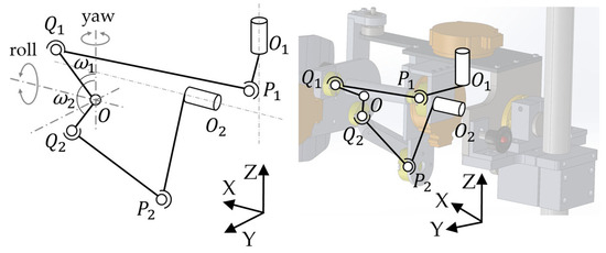
Figure 10.
Link model for scapula motion and its corresponding mechanism in CAD.
When θ1 and θ2 are the angle of the 1st and 2nd motor, respectively, and φ and ψ are the yaw and roll angle of scapula, respectively, φ is the angle of basic motion No. 1 and ψ is the angle of basic motion No. 2 in Figure 3. Hence, the desired kinematics of the links above can be defined as the relationship between θ1, θ2, and φ, ψ. Moreover, from the descriptions above, it is also clear that the segment lengths of |O1P1|, |O2P2|, |P1Q1|, |P2Q2|, |OQ1|, |OQ2|, |OO1|, and |OO2| are all constant and known.
Based on knowledge of the spherical coordinates, and can be obtained as
where ω1 and ω2 are the offset angles of segment OO1 and OO2, respectively, which are constant and known as well.
Similarly, based on knowledge of the circular coordinates, and can be obtained as
Let
Since we have
based on the basic characteristics of the vector, Equations (7) and (8) can be reorganized as
and finally as
Substituting Equations (1)–(6) into Equations (11) and (12), we have
where coefficients A, B, C, D, E, and F can be obtained as
A(φ, ψ)sinθ1 + B(φ, ψ)cosθ1 + C(φ, ψ) = 0,
D(φ, ψ)sinθ2 + E(φ, ψ)cosθ2 + F(φ, ψ) = 0,
A(φ, ψ) = 2|O1P1|(XO1 − |OQ1|sin(ψ + ω1)cosφ),
B(φ, ψ) = 2|O1P1|(YO1 − |OQ1|sin(ψ + ω1)sinφ),
C(φ, ψ) = |OO1|2 + |OQ1|2 + |O1P1|2-|Q1P1|2 − 2|OQ1|(XO1sin(ψ + ω1)cosφ + YO1sin(ψ + ω1)sinφ + ZO1cos(ψ + ω1)),
D(φ, ψ) = 2|O2P2|(YO2 − |OQ2|sin(ψ + ω2)sinφ),
E(φ, ψ) = 2|O2P2|(−ZO2 + |OQ2|cos(ψ + ω2)),
F(φ, ψ) = |OO2|2 + |OQ2|2 + |O2P2|2-|Q2P2|2 − 2|OQ2|(XO2sin(ψ + ω2)cosφ + YO2sin(ψ + ω2)sinφ + ZO2cos(ψ + ω2)).
Equations (13) and (14) are obtained as inverse kinematics, and their numerical solutions can be solved with the help of calculation software.
4. Experiments
In this section, the results of evaluation experiments regarding (a) the ROM of the developed apparatus for motions No. 1–6 in Figure 3, and (b) an angle data comparison between teaching mode and playback mode for the six motions and an arbitrary training motion combining multiple basic motions, are presented. Regarding angle data, for each motion, only the data from the motor(s) mainly involved will be presented, which are: (a) the 1st and 2nd motors for motions No. 1 and No. 2; (b) the 4th motor for motion No. 3; (c) the 3rd motor for motion No. 4; (d) the 4th motor for motion No. 5; (e) the 5th motor for motion No. 6; and (f) the 1st–5th motors for an arbitrary training motion. Snapshots of experiment videos are given in Appendix A instead of this section, in consideration of the total space they occupy.
In this article, the first author (male, in his 30 s) was chosen as the subject instead of frozen shoulder patients, and another author (male, in his 40 s) performed the CPM motion instead of a professional physical therapist. In playback mode, subjects were asked to relax, just as a patient is asked to do by a therapist in a real rehabilitation scenario.
4.1. ROM of the Developed Apparatus
Table 2.
ROM of the developed apparatus and reference values. All values are in degrees.
Consequently, the ROMs of the apparatus for three motions were equal or larger than the reference values (No. 1, No. 2, and No. 6), the ROM of one motion was slightly smaller than the reference values (No. 3), and the ROM of two motions were noticeably smaller than the reference values (No. 4, No. 5). Note that the ROM of motion No. 2 for the apparatus was designed to be symmetric (+20 deg to −20 deg), because the whole apparatus may rotate 180 deg about X-axis to apply to both the left and right scapulas of a patient, and the reference value of +20 deg–−10 deg must be satisfied for both two sides.
Although the slight lack of ROM for No. 3 may be negligible, the insufficient ROM for motions No. 4 and No. 5, due to the limitation of movable range caused by the mechanical design and the shape of “scapula plate” mentioned in Figure 4, needs to be improved.
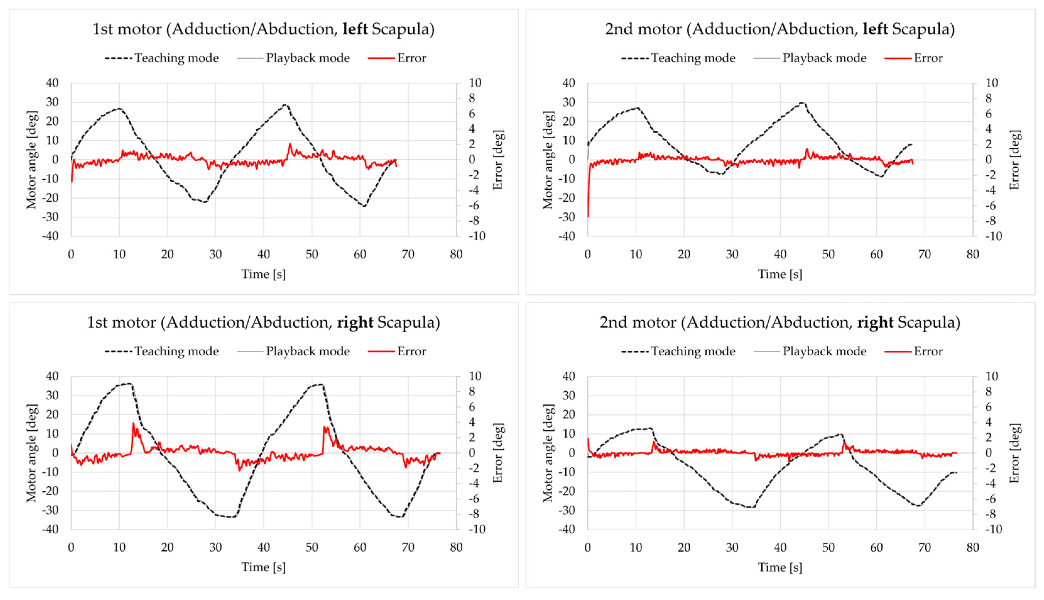
4.2. Teaching and Playback of Motion No. 1: Abduction/Adduction of Scapula
The angle of the 1st and 2nd motors in both teaching and playback mode are presented in Figure 11, along with the error value (playback–teaching). The angle data apply to the vertical axis on the left, and error data apply to the vertical axis on the right, which are the same for all the remaining figures in this section.
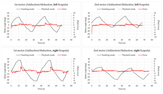
Figure 11.
Motor angle data for motion No. 1.
Except for the initial state, all errors were within the range of [−4 deg, 4 deg], which is acceptable.
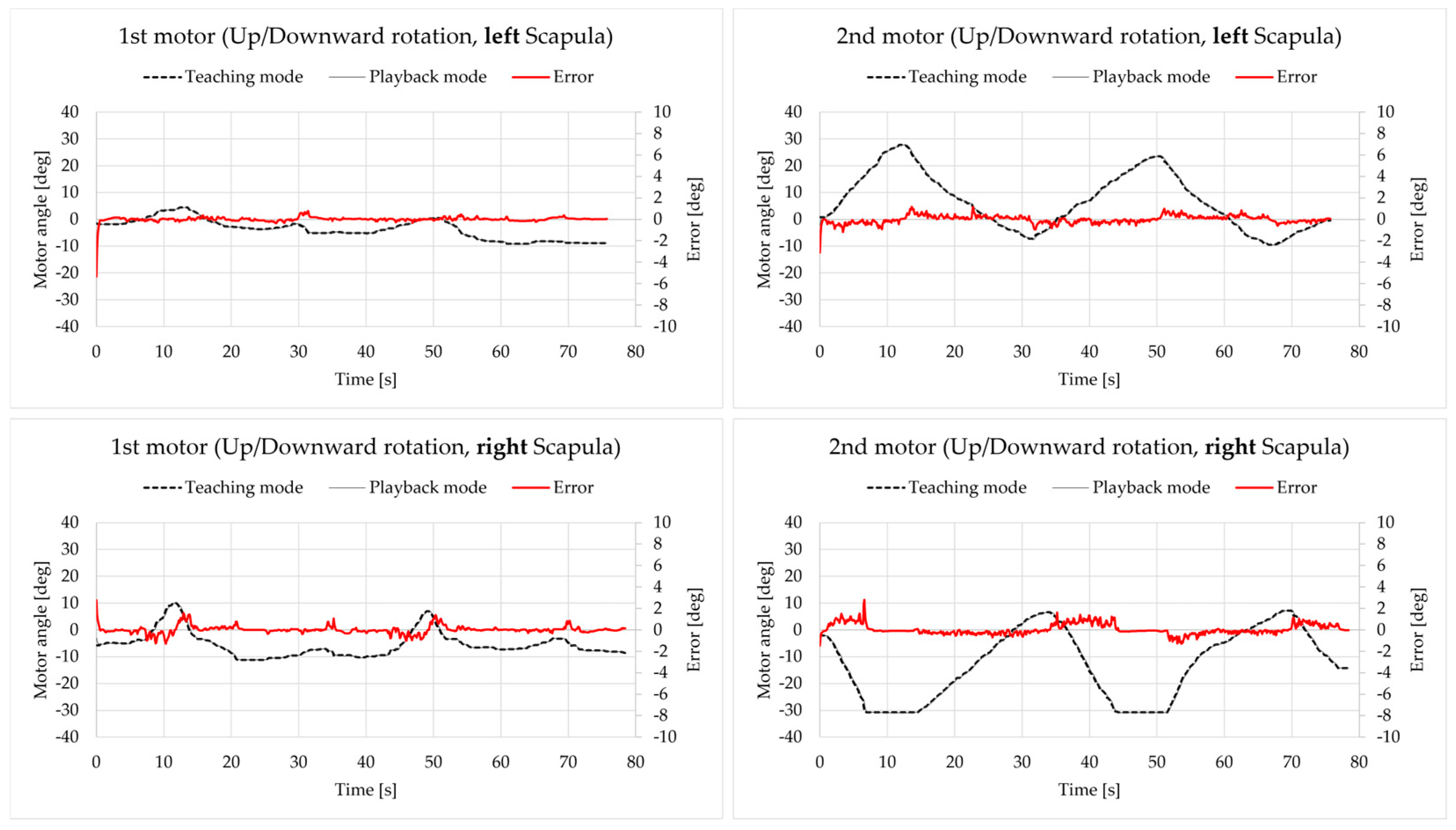
4.3. Teaching and Playback of Motion No. 2: Upward/Downward Rotation of the Scapula
The results are presented in Figure 12. Except for the initial state, all errors were within the range of [−4 deg, 4 deg], which is acceptable.
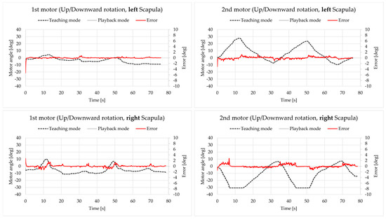
Figure 12.
Motor angle data for motion No. 2.
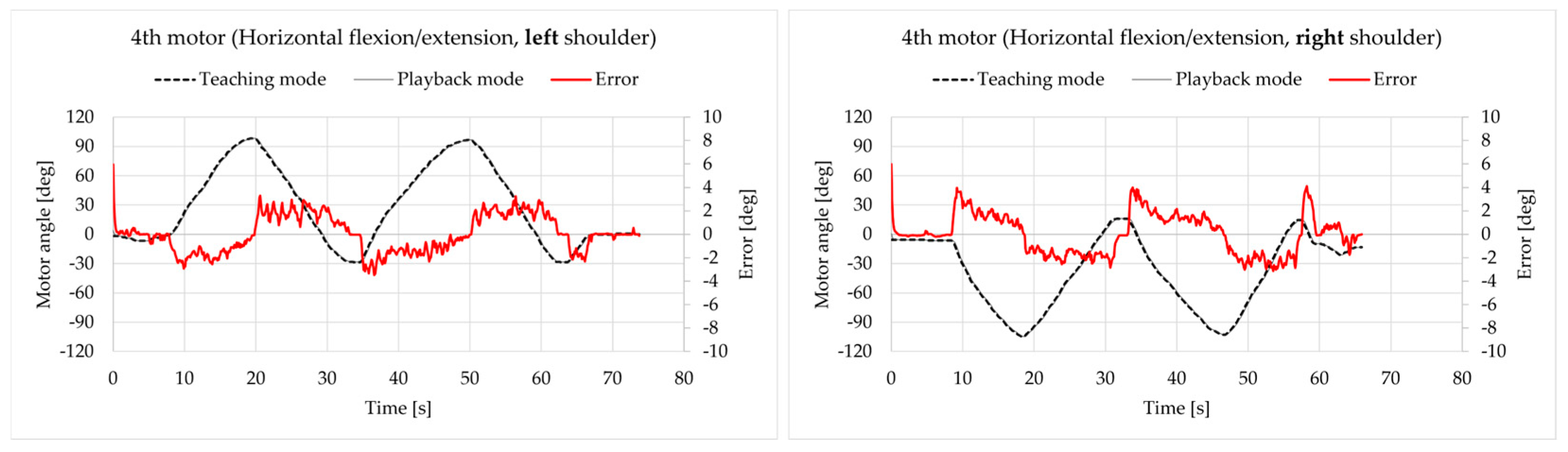
4.4. Teaching and Playback of Motion No. 3: Horizontal Flexion/Extension of the Shoulder Joint
The results are presented in Figure 13. All errors were within the range of [−5 deg, 5 deg], which is acceptable.
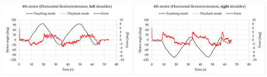
Figure 13.
Motor angle data for motion No. 3.
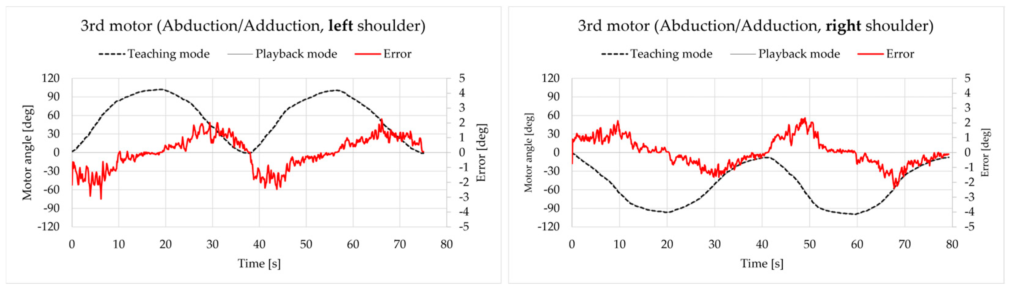
4.5. Teaching and Playback of Motion No. 4: Abduction/Adduction of the Shoulder Joint
The results are presented in Figure 14. All errors were within the range of [−4 deg, 4 deg], which is acceptable.

Figure 14.
Motor angle data for motion No. 4.
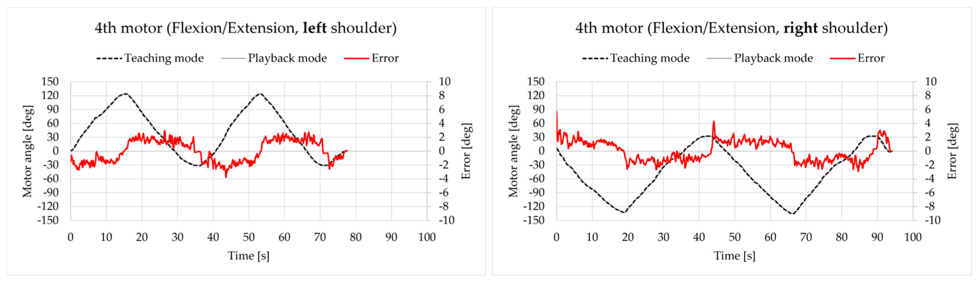
4.6. Teaching and Playback of Motion No. 5: Flexion/Extension of the Shoulder Joint
The results are presented in Figure 15. All errors were within the range of [−6 deg, 6 deg], which is a little worse than the results above but is still acceptable.
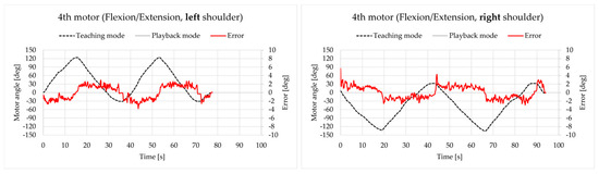
Figure 15.
Motor angle data for motion No. 5.
4.7. Teaching and Playback of Motion No. 6: External/Internal Rotation of the Shoulder Joint
The results are presented in Figure 16. Although most errors were within the range of [−5 deg, 5 deg], some peak values went beyond this range, which are approaching −8 deg and 8 deg. It seems that the tracking performance of the 5th motor is not as good as the others, and this was especially the case when there was a higher acceleration. A representative instance was the behavior of the 5th motor for the left shoulder for the period of 25 s–40 s. The authors are also considering improving the performance of motion No. 6 by replacing the existing motor for a new one, along with other measures, in the future.
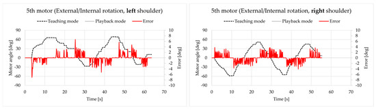
Figure 16.
Motor angle data for motion No. 6.
4.8. Teaching and Playback of an Arbitrary Training Motion
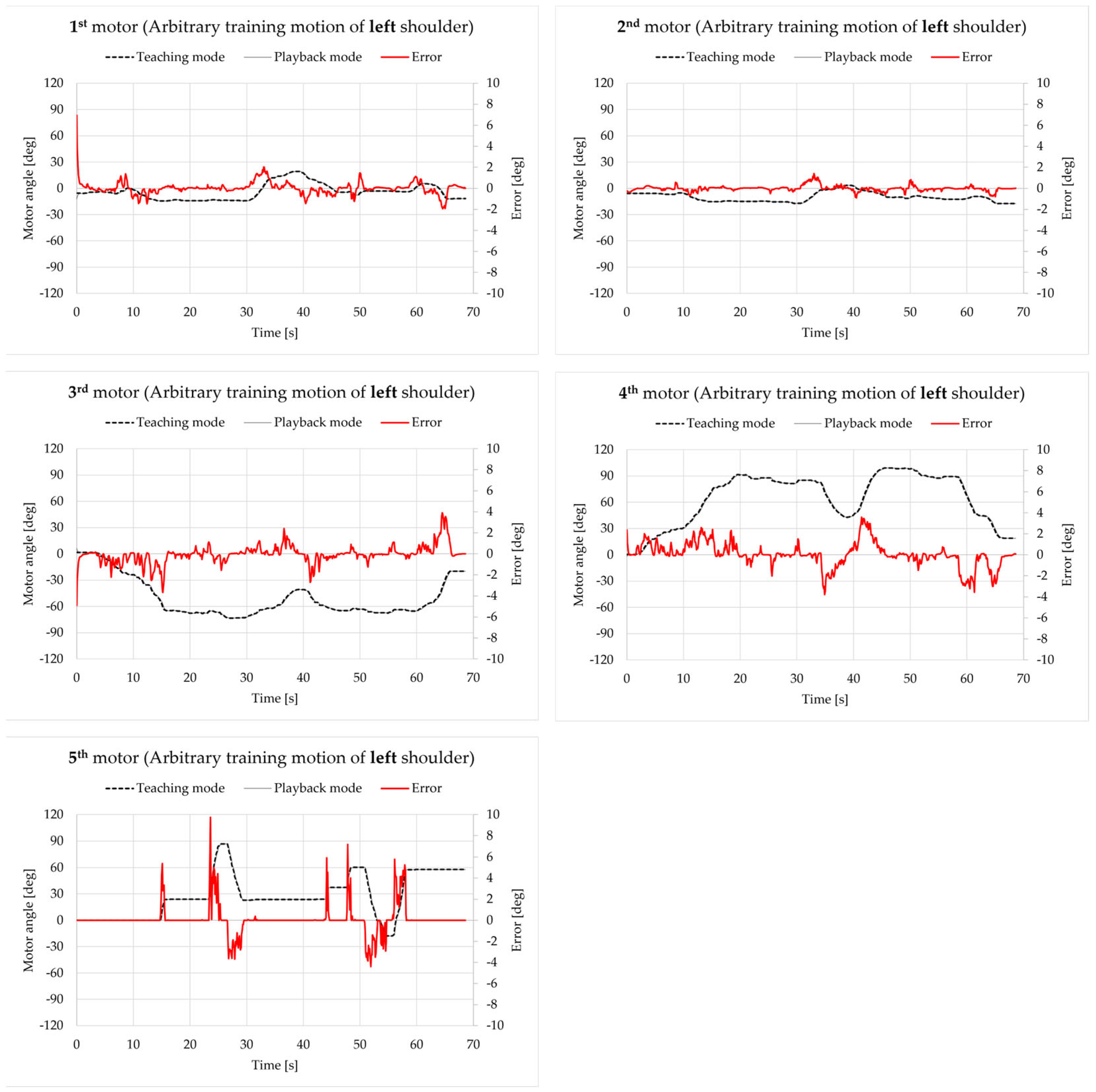
As a sum of all six basic motions described above, an arbitrary training motion was performed for both the left and right shoulders. The authors tried to have all five motors involved in this motion simulate the actual training motion. Figure 17 presents the results for the left shoulder.
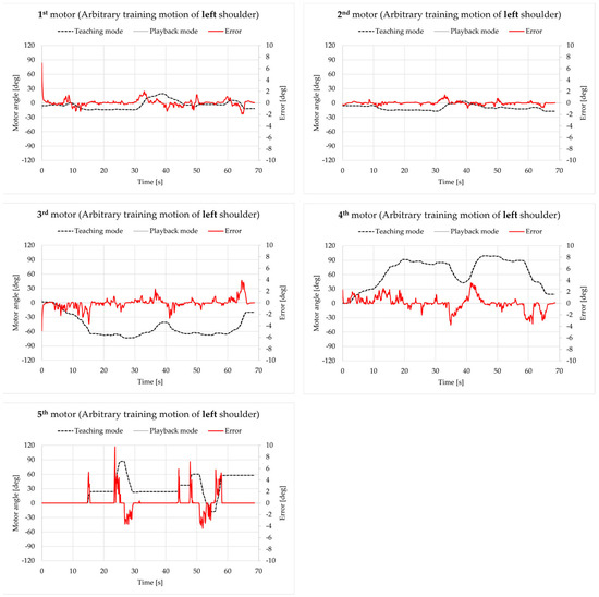
Figure 17.
Motor angle data for an arbitrary training motion on the left shoulder.
Except for the initial state, the errors of the 1st–4th motor were all within the range of [−5 deg, 5 deg], which is acceptable. However, just like the case for motion No. 6, the errors of the 5th motor, especially for the peak value, were much larger (exceeding −10 deg).
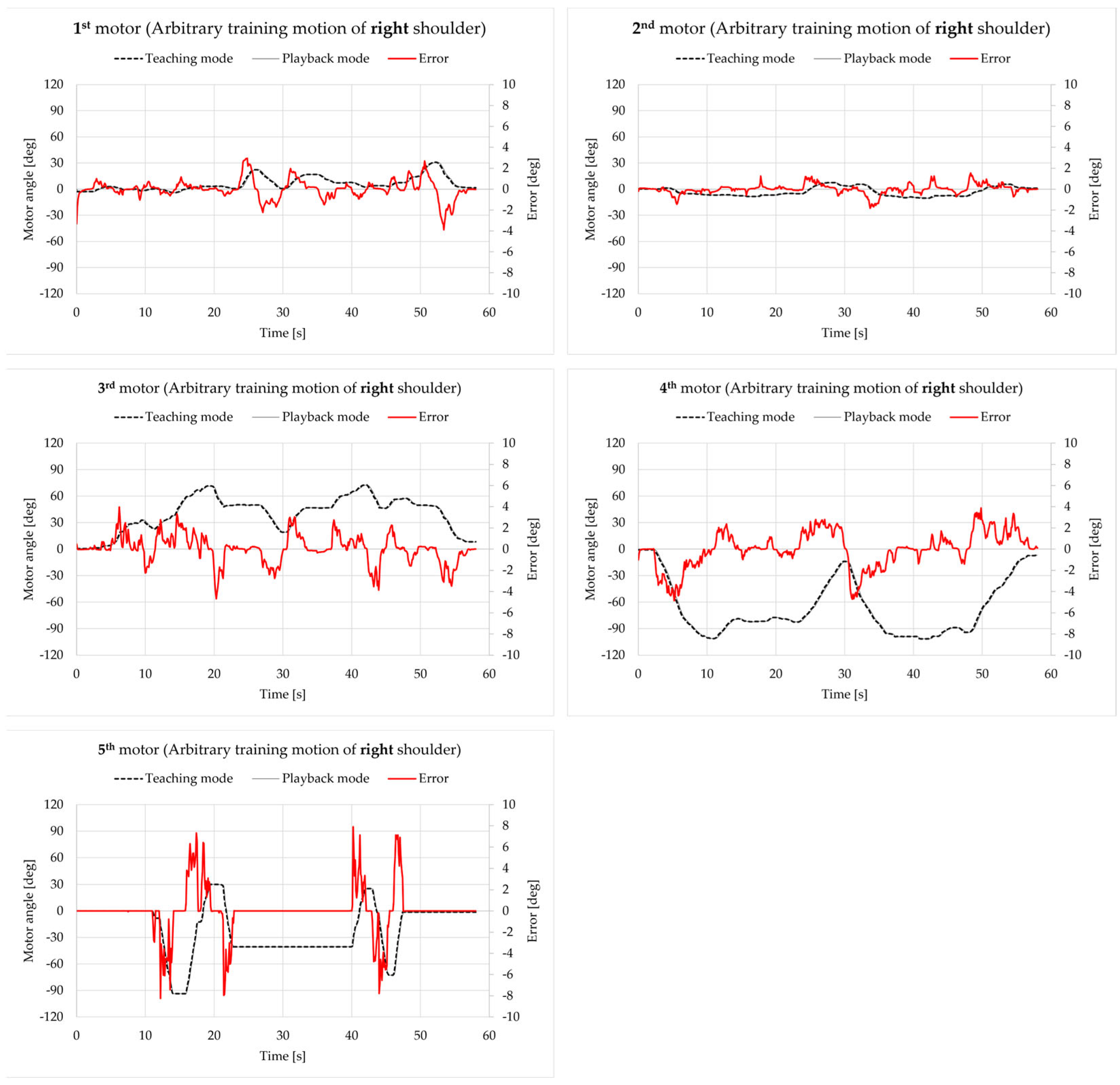
Figure 18 presents the results of the right shoulder. Except for the initial state and a peak, the errors of the 1st–4th motor were all within the range of [−6 deg, 6 deg], which is acceptable as well. Similar to the results in Figure 17, the errors of the 5th motor with the peak value up to about 10 deg were worse than the errors of the 1st–4th motor.
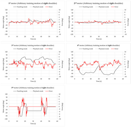
Figure 18.
Motor angle data for an arbitrary training motion on the right shoulder.
To summarize the results from Section 4.2 to Section 4.8, the errors of the 1st–4th motor were all within the range of [−6 deg, 6 deg] (excluding initial states), which are hardly noticeable and thus are acceptable, while the errors of the 5th motor went above 10 deg, which could be a potential issue. In the authors’ opinion, these errors might come from low data frequency of 10 Hz in both teaching and playback modes, and angle data may be missed between loops. Therefore, the authors plan to further improve the performance for the 5th motor and try to increase the data frequency in teaching and playback mode. Another potential issue can be seen in Figure A11, Figure A12, Figure A13 and Figure A14. When the apparatus was performing any motion involving the 5th motor, there seemed to be slips between the upper arm/elbow and the upper arm cuff; this needs to be reduced in future as well.
5. Conclusions and Future Works
This article describes a robot developed for the rehabilitation of frozen shoulder that is capable of (1) training based on the motion of the patient’s scapula and (2) recording and reproducing the training motion with high accuracy. This has not been realized by former and existing CPM machines on the market.
To begin, the entire system is introduced, including its major features (hardware, configuration, kinematics, and others). Afterwards, experimental results are shown to validate and evaluate its capabilities.
With the improvements and innovations explained in this article, the robot could be better in the following points, which are also prospective work for the authors: (1) evaluation experiments with physical therapists and patients; (2) improving the performance of the motions involving the 5th motor and increasing the data frequency of all five motors; (3) improving the design of the mechanical parts and supporting parts to expand the ROM and reduce unnecessary slip between the apparatus and the patient.
Author Contributions
Conceptualization, X.S. and H.T.; methodology, K.M. and K.I.; software, D.K.; validation, D.K.; formal analysis, X.S.; investigation, X.S.; resources, H.T.; data curation, D.K.; writing—original draft preparation, X.S.; writing—review and editing, X.S., K.M., H.K., K.I. and H.T.; visualization, X.S.; supervision, H.T.; project administration, K.M.; funding acquisition, H.K. and H.T. All authors have read and agreed to the published version of the manuscript.
Funding
This research was funded by JSPS KAKENHI Grant Number 22K12934.
Institutional Review Board Statement
The study was conducted in accordance with the Declaration of Helsinki and approved by the Institutional Ethics Committee of the University of Yamanashi (Application No.: 2024-007-2) on 2025/1/27.
Data Availability Statement
The original contributions presented in the study are included in the article, further inquiries can be directed to the corresponding author.
Acknowledgments
This article is a revised and expanded version of a paper entitled “Development of a Rehabilitation Robot for the Frozen Shoulder Considering Shoulder Girdle Motion”, which was presented at the Symposium on Mechanism Design for Robotics (MEDER 2024) held in Timisoara, Romania, 27–29 June 2024.
Conflicts of Interest
The authors declare no conflicts of interest.
Appendix A
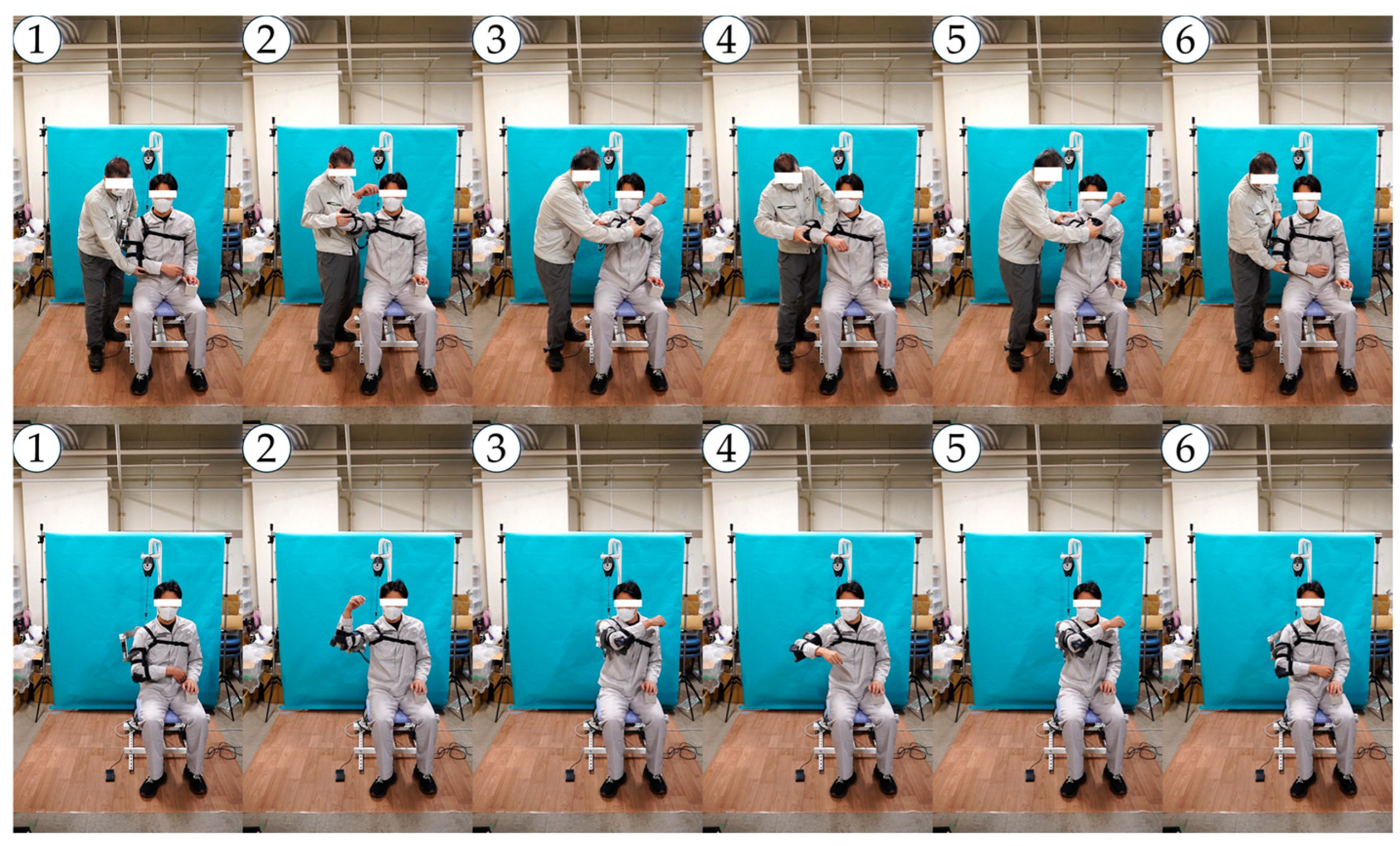
The snapshots of all experiments mentioned in this article are shown here from motion No. 1 to No. 6 and ends with snapshots of arbitrary training motions on both left and right shoulders, which are 14 cases in total. The upper row is the snapshots in teaching mode and the lower row is the snapshots in playback mode for each figure.
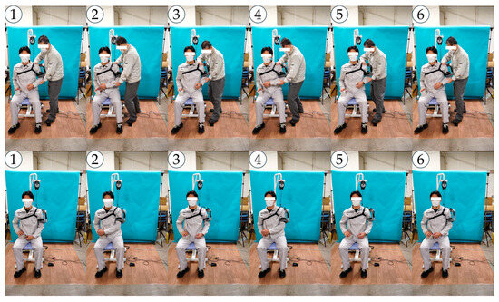
Figure A1.
Snapshots of motion No. 1 of the left shoulder.
Figure A1.
Snapshots of motion No. 1 of the left shoulder.
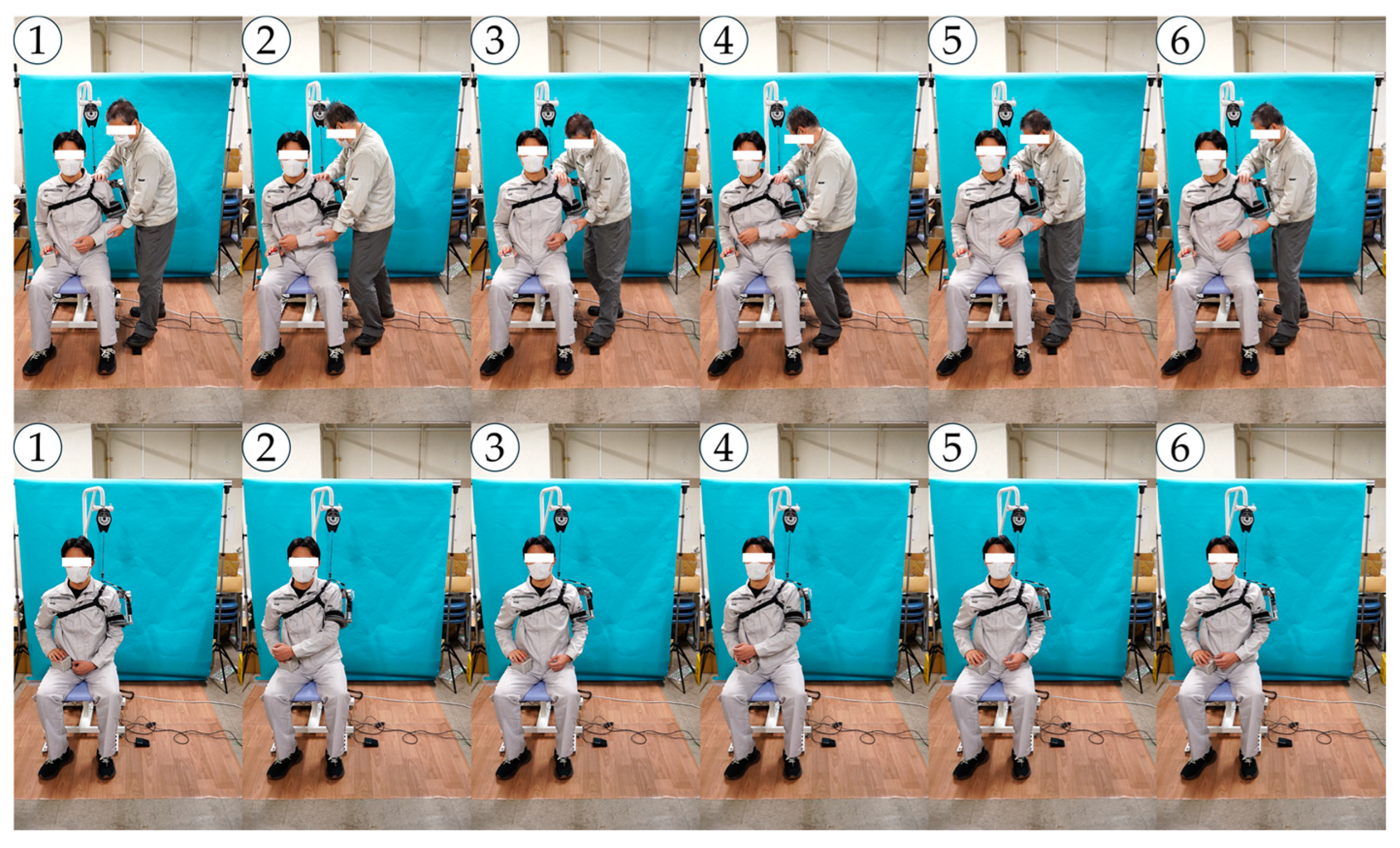
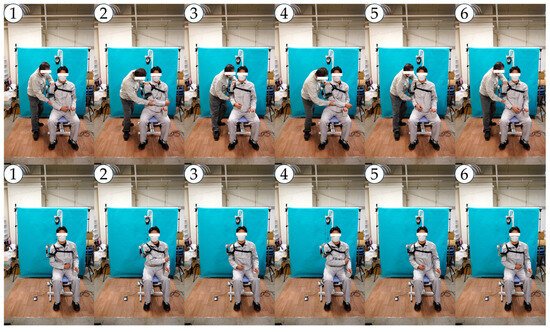
Figure A2.
Snapshots of motion No. 1 of the right shoulder.
Figure A2.
Snapshots of motion No. 1 of the right shoulder.
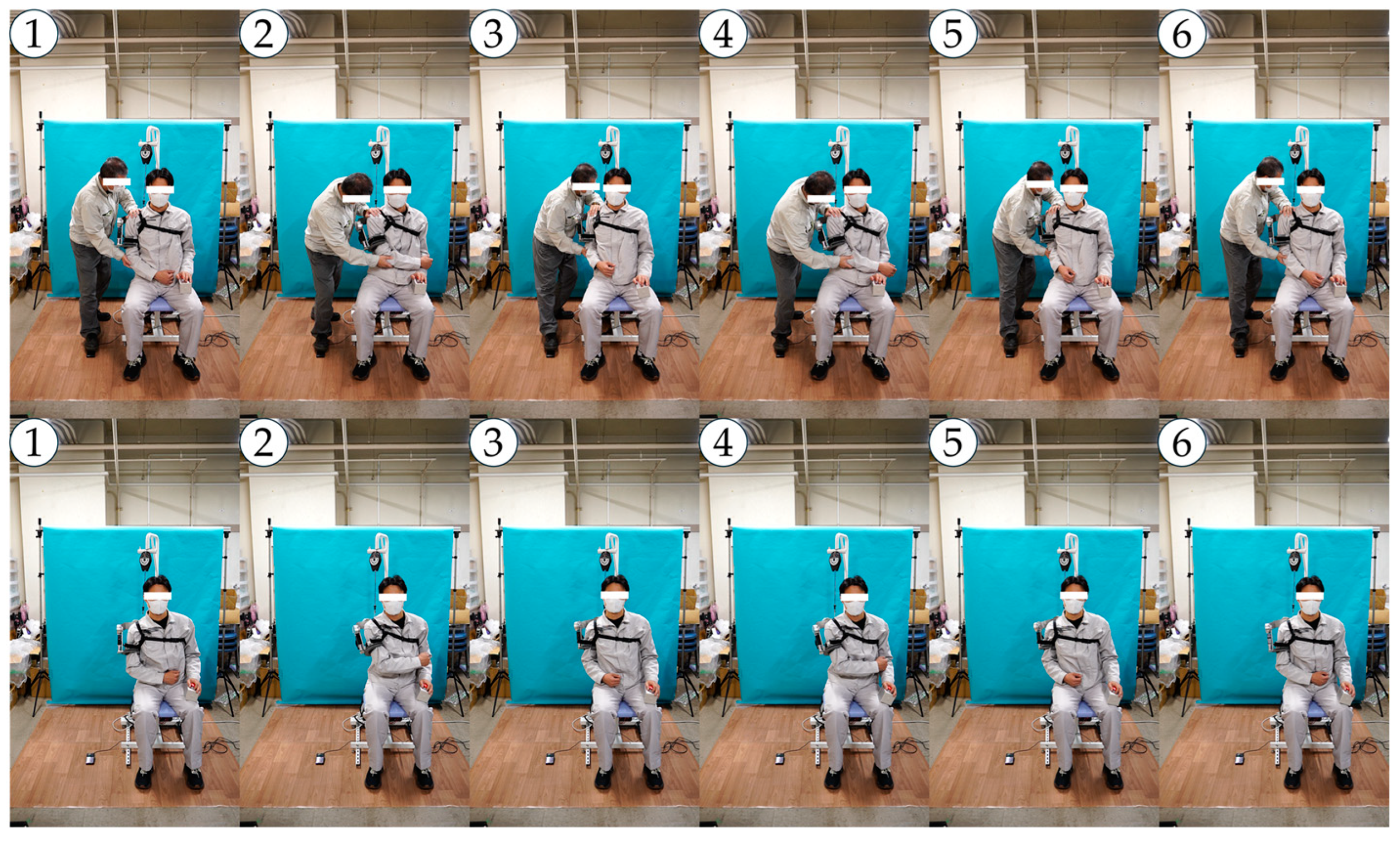
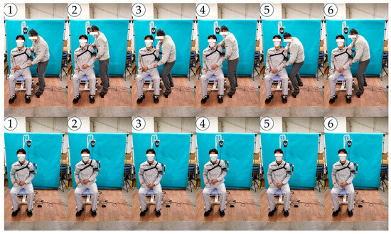
Figure A3.
Snapshots of motion No. 2 of the left shoulder.
Figure A3.
Snapshots of motion No. 2 of the left shoulder.
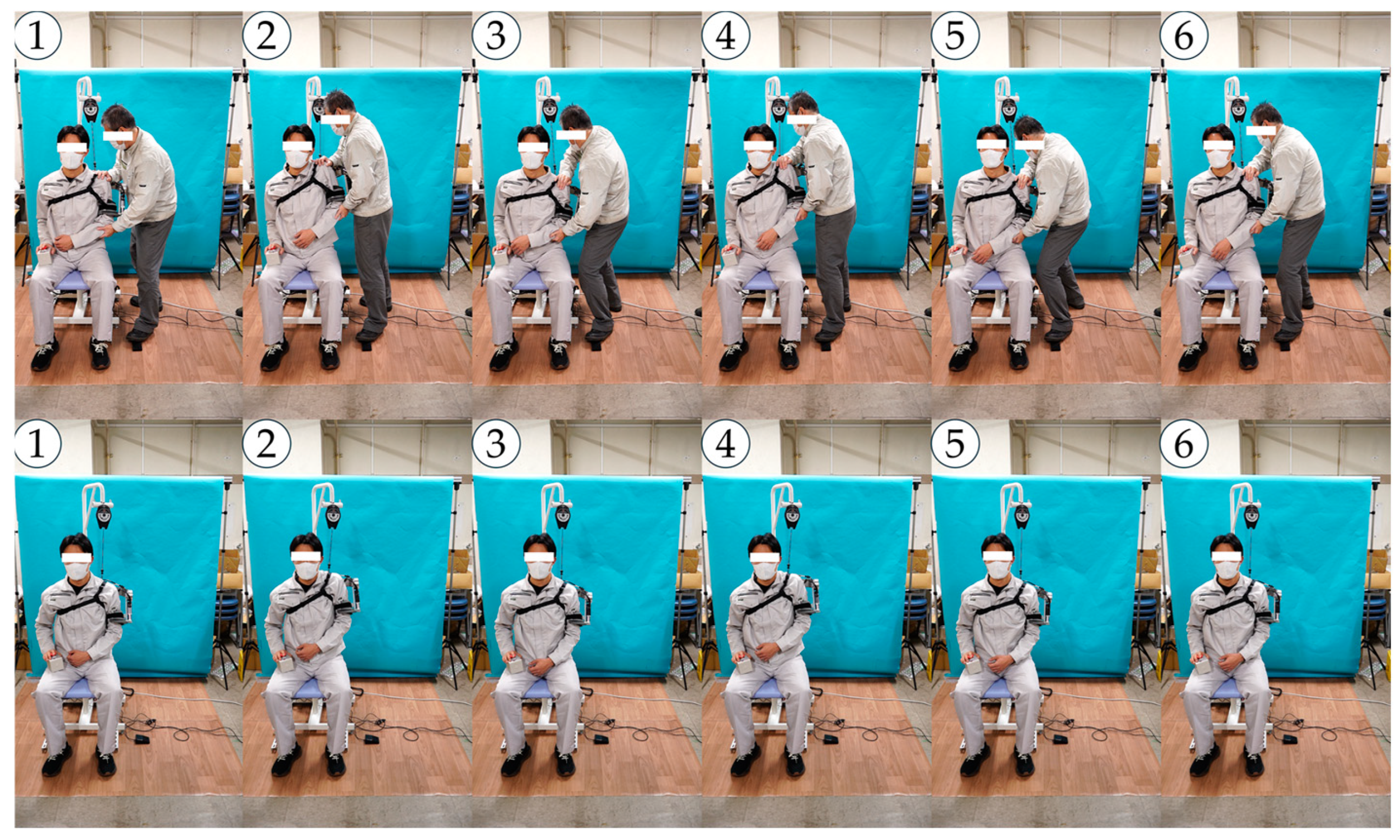
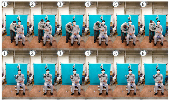
Figure A4.
Snapshots of motion No. 2 of the right shoulder.
Figure A4.
Snapshots of motion No. 2 of the right shoulder.
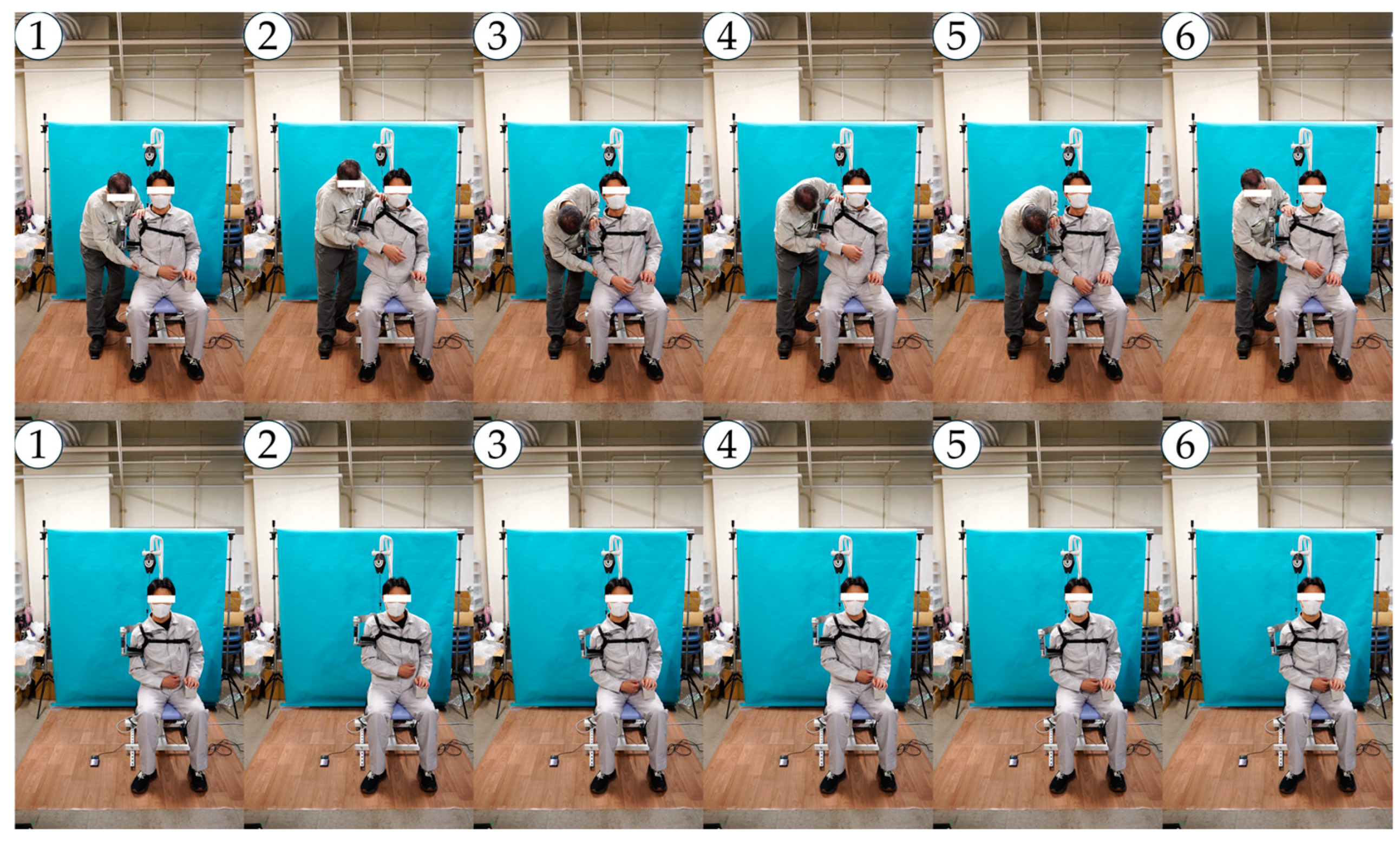
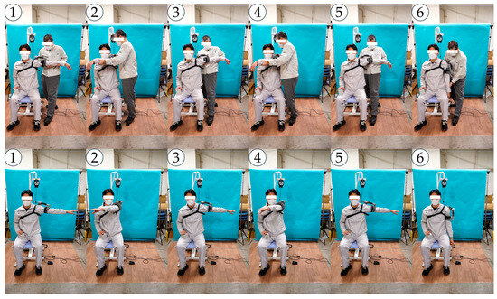
Figure A5.
Snapshots of motion No. 3 of the left shoulder.
Figure A5.
Snapshots of motion No. 3 of the left shoulder.
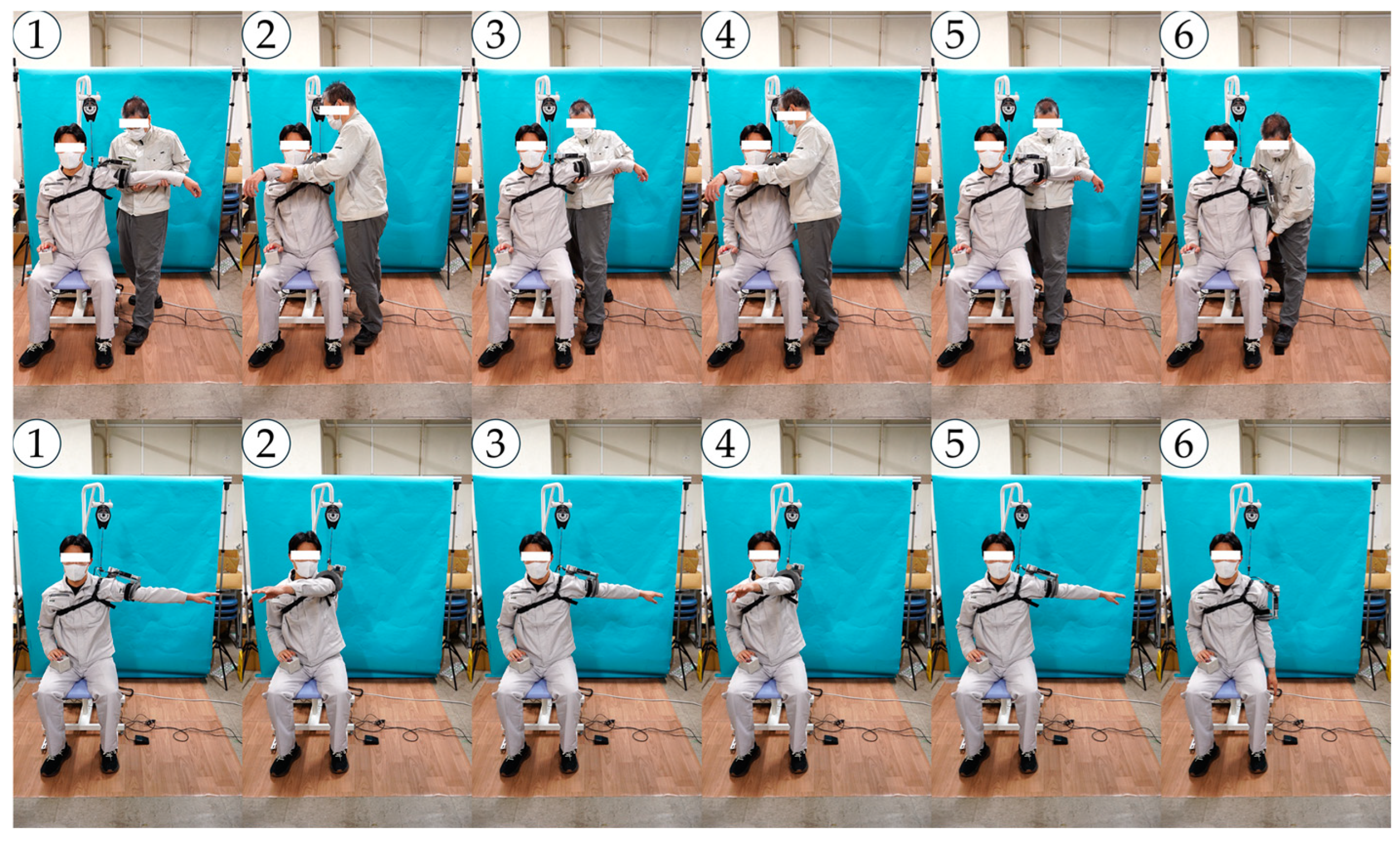
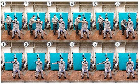
Figure A6.
Snapshots of motion No. 3 of the right shoulder.
Figure A6.
Snapshots of motion No. 3 of the right shoulder.
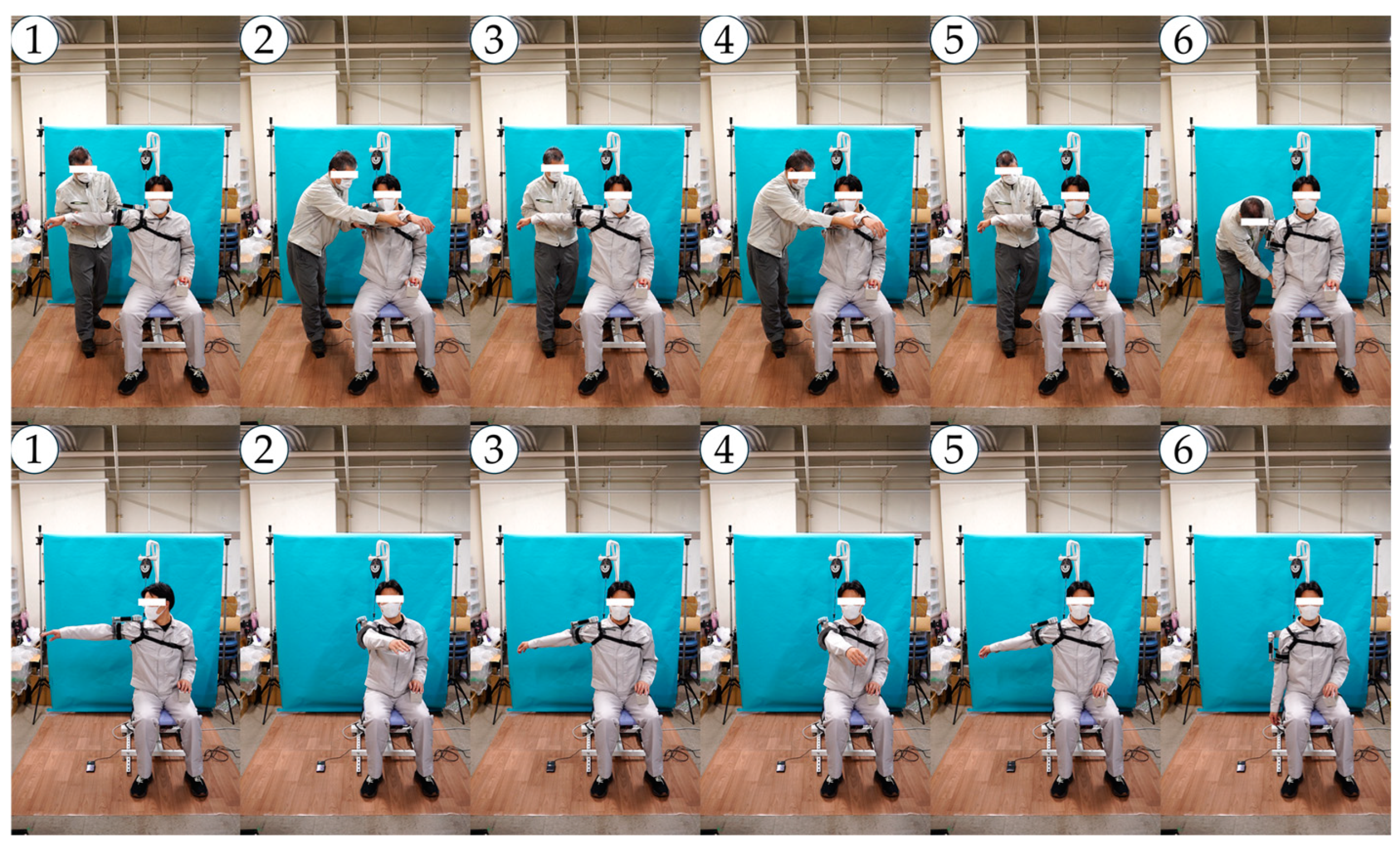
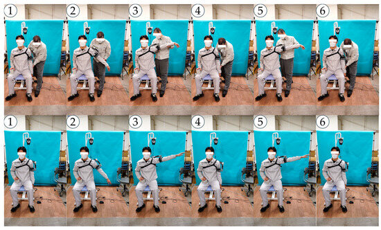
Figure A7.
Snapshots of motion No. 4 of the left shoulder.
Figure A7.
Snapshots of motion No. 4 of the left shoulder.
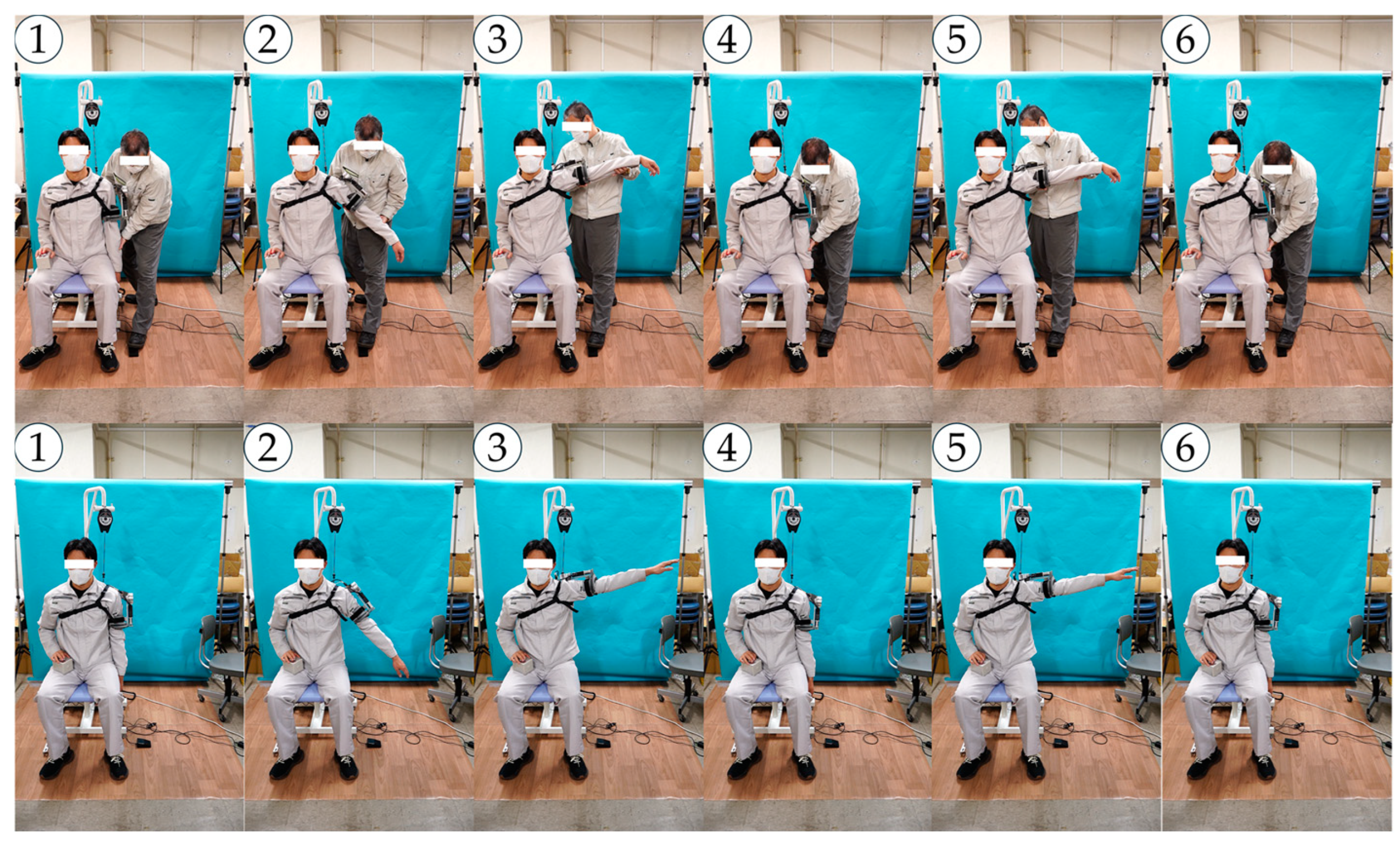
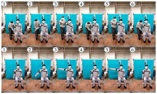
Figure A8.
Snapshots of motion No. 4 of the right shoulder.
Figure A8.
Snapshots of motion No. 4 of the right shoulder.
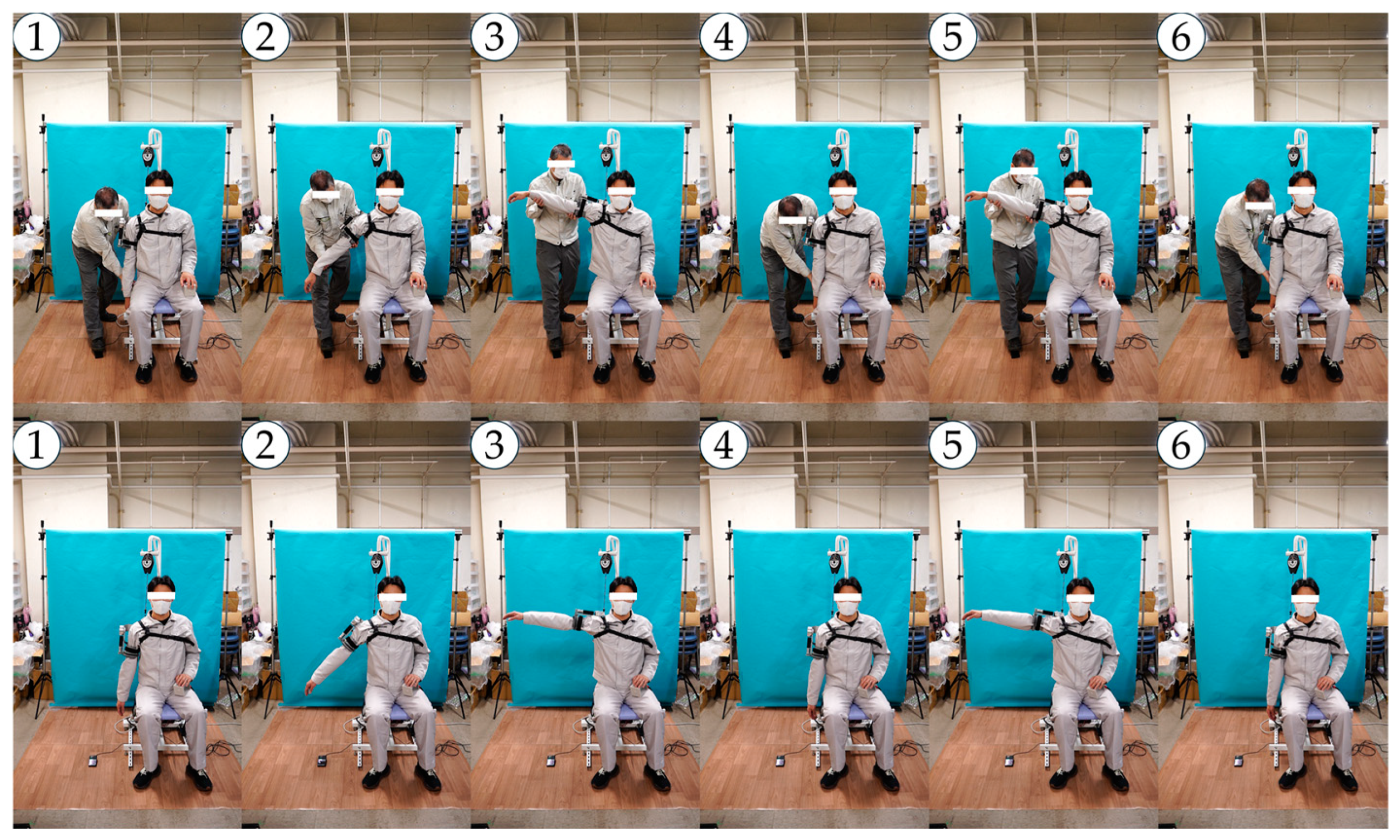

Figure A9.
Snapshots of motion No. 5 of the left shoulder.
Figure A9.
Snapshots of motion No. 5 of the left shoulder.
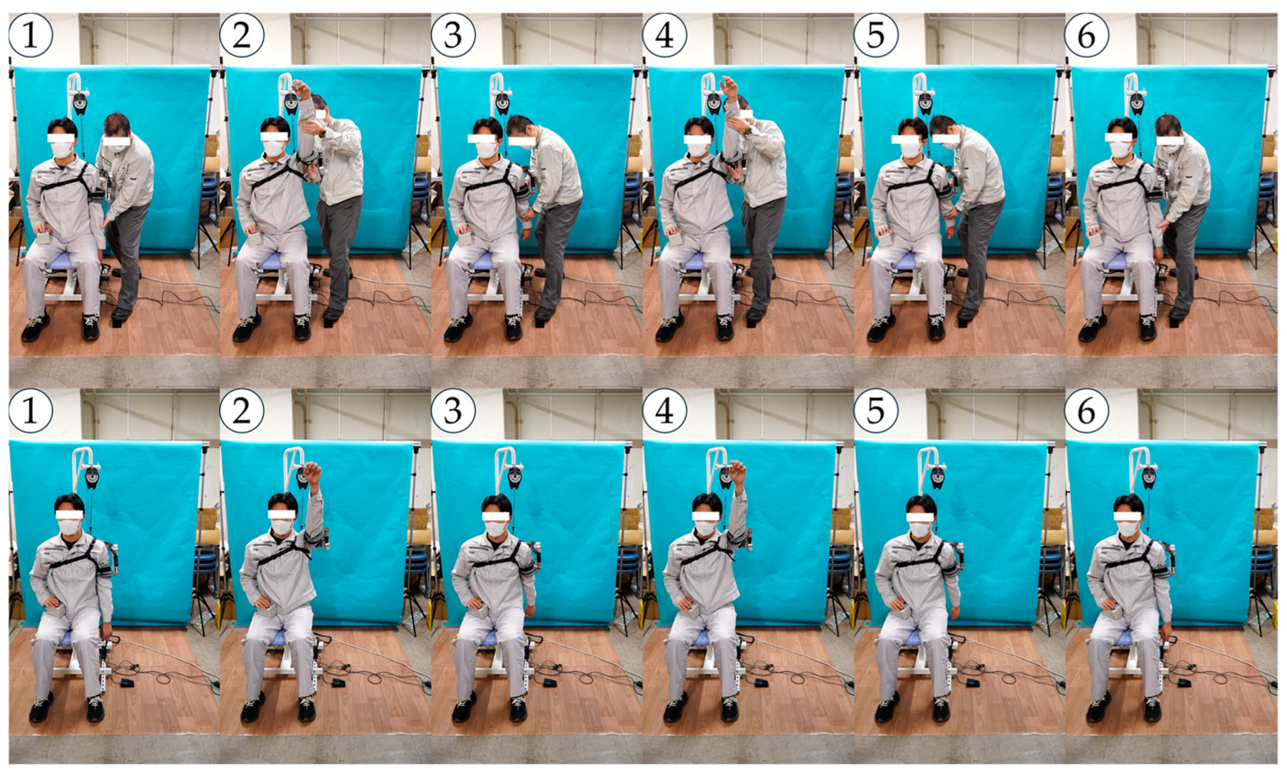
Figure A10.
Snapshots of motion No. 5 of the right shoulder.
Figure A10.
Snapshots of motion No. 5 of the right shoulder.
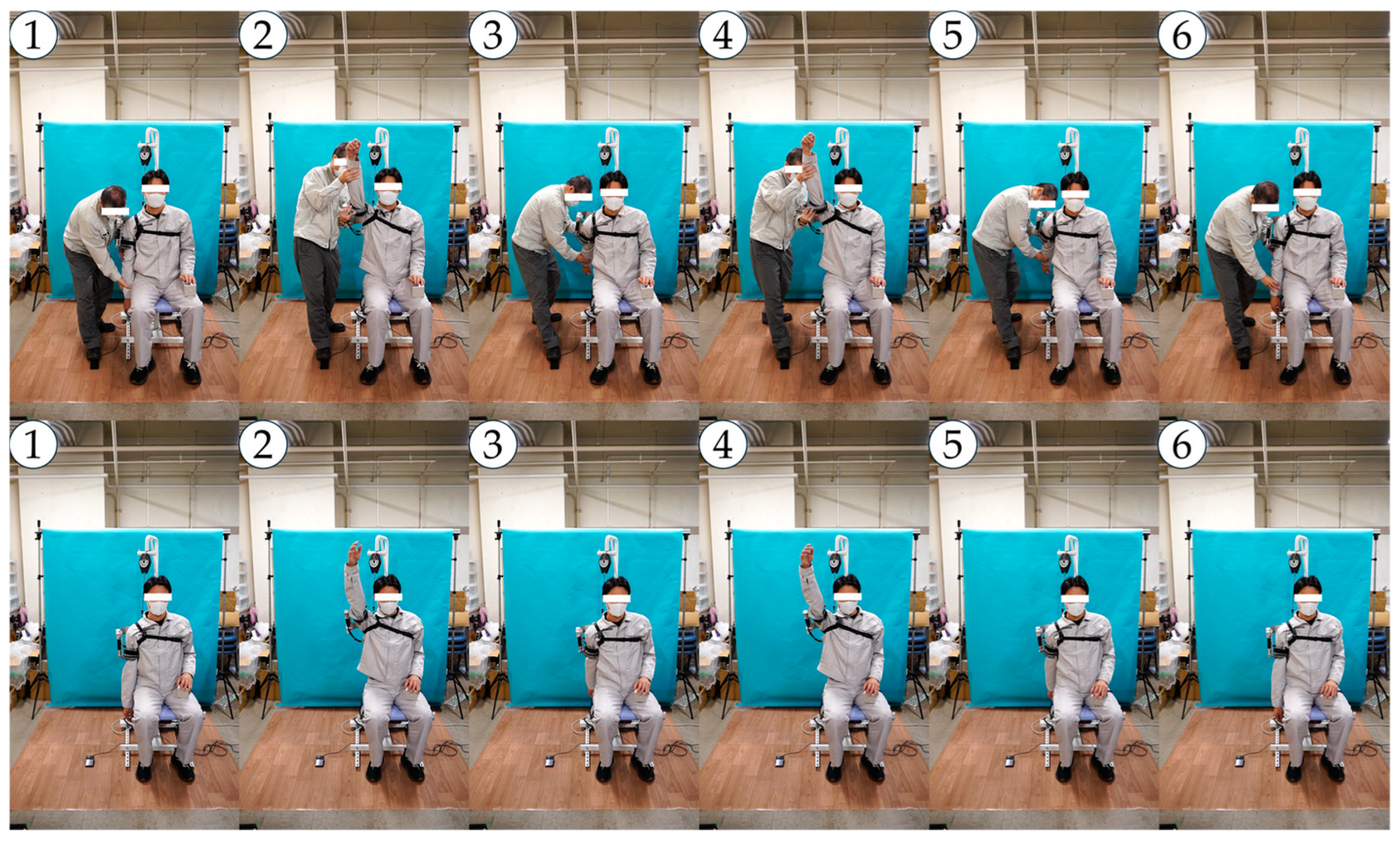
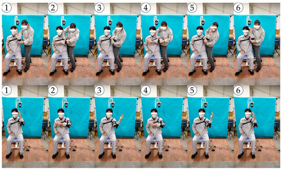
Figure A11.
Snapshots of motion No. 6 of the left shoulder.
Figure A11.
Snapshots of motion No. 6 of the left shoulder.
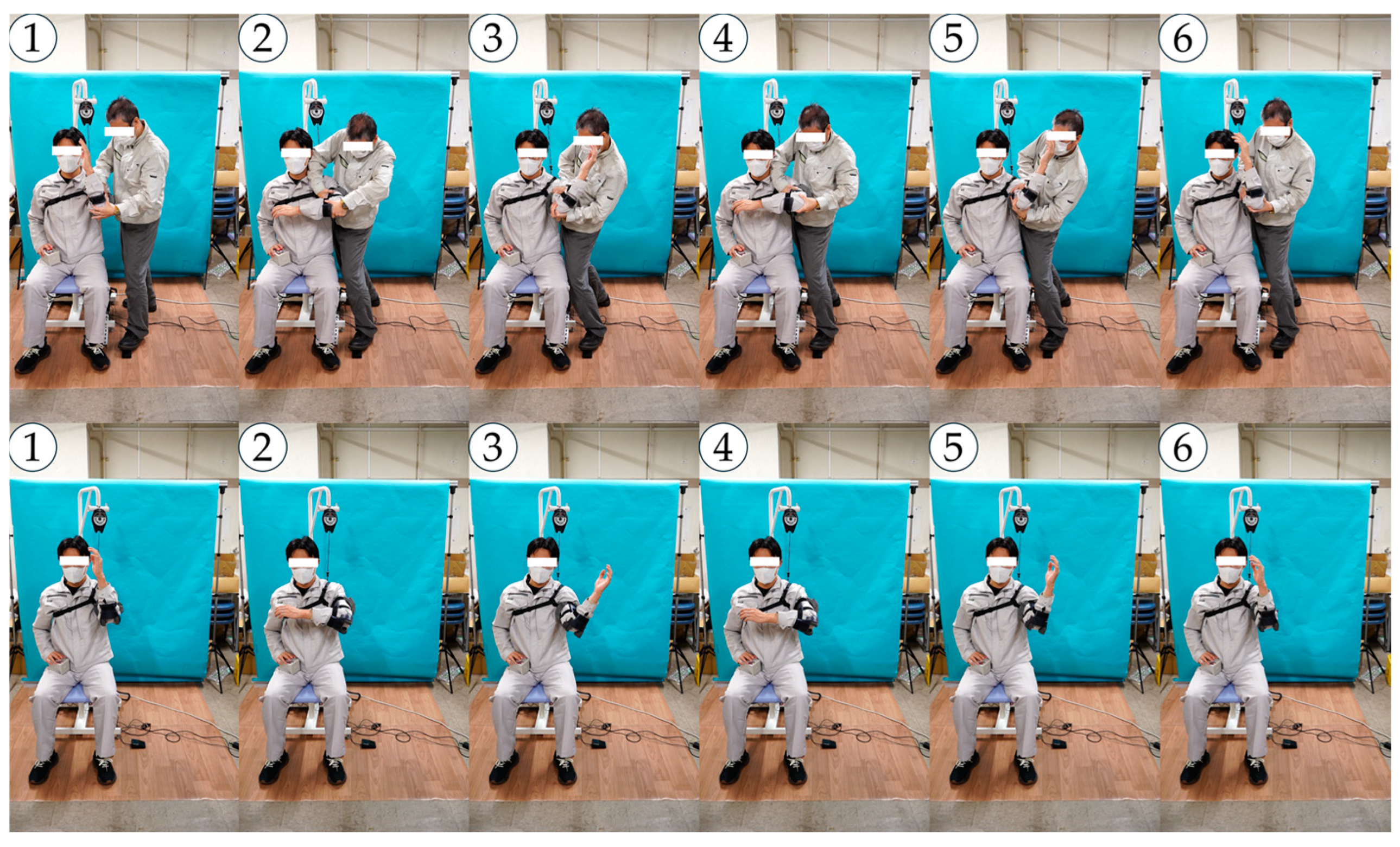
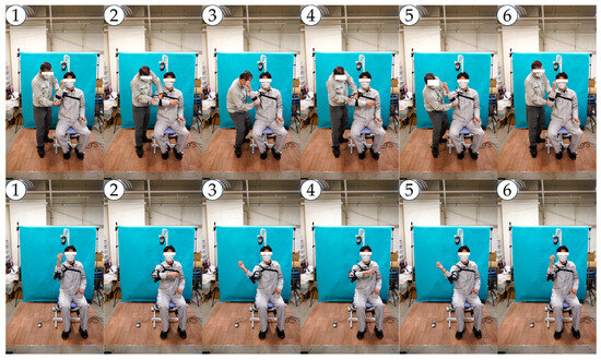
Figure A12.
Snapshots of motion No. 6 of the right shoulder.
Figure A12.
Snapshots of motion No. 6 of the right shoulder.

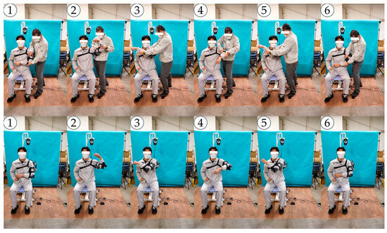
Figure A13.
Snapshots of an arbitrary training motion of the left shoulder.
Figure A13.
Snapshots of an arbitrary training motion of the left shoulder.
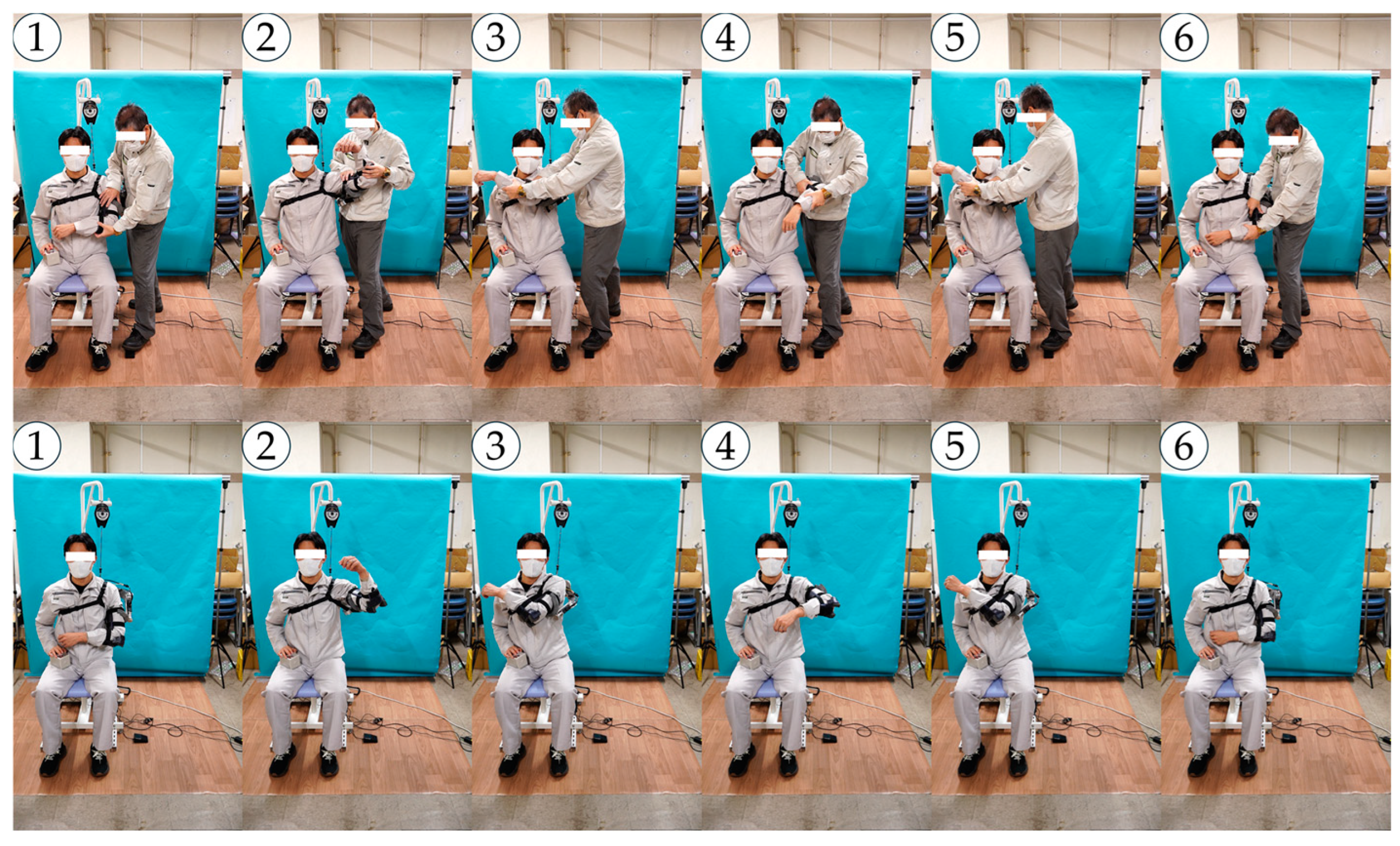
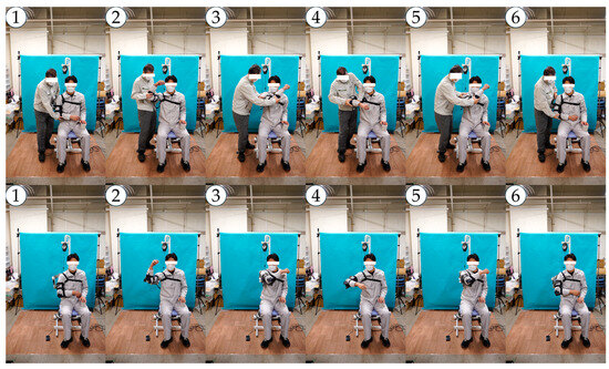
Figure A14.
Snapshots of an arbitrary training motion of the right shoulder.
Figure A14.
Snapshots of an arbitrary training motion of the right shoulder.
References
- Chan, H.; Pua, P.; How, C. Physical Therapy in the Management of Frozen Shoulder. Singap. Med. J. 2017, 58, 685–689. [Google Scholar] [CrossRef] [PubMed]
- Cho, C.-H.; Bae, K.-C.; Kim, D.-H. Treatment Strategy for Frozen Shoulder. Clin. Orthop. Surg. 2019, 11, 249. [Google Scholar] [CrossRef]
- Dundar, U.; Toktas, H.; Cakir, T.; Evcik, D.; Kavuncu, V. Continuous Passive Motion Provides Good Pain Control in Patients with Adhesive Capsulitis. Int. J. Rehabil. Res. 2009, 32, 193–198. [Google Scholar] [CrossRef]
- Salter, R.B.; Hamilton, H.W.; Wedge, J.H.; Tile, M.; Torode, I.P.; O’Driscoll, S.W.; Murnaghan, J.J.; Saringer, J.H. Clinical Application of Basic Research on Continuous Passive Motion for Disorders and Injuries of Synovial Joints: A Preliminary Report of a Feasibility Study. J. Orthop. Res. 1983, 1, 325–342. [Google Scholar] [CrossRef]
- Celik, D. Comparison of the Outcomes of Two Different Exercise Programs on Frozen Shoulder. Acta Orthop. Traumatol. Turc. 2010, 44, 285–292. [Google Scholar] [CrossRef] [PubMed]
- Kinetec Centura Shoulder CPM. Available online: https://www.medcomgroup.com/kinetec-centura-shoulder-cpm/ (accessed on 20 October 2024).
- Centura Lite—Single Motor. Available online: https://www.kinetecusa.com/shop/cpm-active/shoulder-cpms/kinetec-centura-lite-single-motor/ (accessed on 20 October 2024).
- ARTROMOT-S4. Available online: https://www.chattanoogarehab.com/artromot-s4-80-00-084c-int (accessed on 20 October 2024).
- Shoulder. Available online: https://kinexmedical.com/products/cpm/shoulder/ (accessed on 20 October 2024).
- Shoulder CPM. Available online: https://www.medcomgroup.com/shoulder-cpm/ (accessed on 20 October 2024).
- Kinetec Centura Shoulder CPM Series 1 Operations Manual.pdf. Available online: https://www.medcomgroup.com/content/Kinetec%20Centura%20Shoulder%20CPM%20Series%201%20Operations%20Manual.pdf (accessed on 20 October 2024).
- Sun, X.; Makino, K.; Kurita, K.; Kaneko, H.; Ishida, K.; Terada, H. Development of a Rehabilitation Robot for the Frozen Shoulder Considering Shoulder Girdle Motion. In Mechanism Design for Robotics; Springer: Cham, Switzerland, 2024; pp. 166–175. [Google Scholar]
- Ishida, K.; Sun, X.; Kaneko, H.; Kurita, D.; Kurita, K.; Makino, K.; Terada, H. Development of Rehabilitation Apparatus for Frozen Shoulder Adapting Each Motion based on Direct Teaching. In Proceedings of the Annual Conference of the IEEE Industrial Electronics Society (IECON2024), Chicago, IL, USA, 3–6 November 2024. [Google Scholar]
- Högfors, C.; Sigholm, G.; Herberts, P. Biomechanical Model of the Human Shoulder—I. Elements. J. Biomech. 1987, 20, 157–166. [Google Scholar] [CrossRef] [PubMed]
- Lenarcic, J.; Stanisic, M. A Humanoid Shoulder Complex and the Humeral Pointing Kinematics. IEEE Trans. Robot. Autom. 2003, 19, 499–506. [Google Scholar] [CrossRef]
- Veeger, H.E.J.; van der Helm, F.C.T. Shoulder Function: The Perfect Compromise between Mobility and Stability. J. Biomech. 2007, 40, 2119–2129. [Google Scholar] [CrossRef] [PubMed]
- Lugo, R.; Kung, P.; Ma, C.B. Shoulder Biomechanics. Eur. J. Radiol. 2008, 68, 16–24. [Google Scholar] [CrossRef] [PubMed]


Disclaimer/Publisher’s Note: The statements, opinions and data contained in all publications are solely those of the individual author(s) and contributor(s) and not of MDPI and/or the editor(s). MDPI and/or the editor(s) disclaim responsibility for any injury to people or property resulting from any ideas, methods, instructions or products referred to in the content. |
© 2025 by the authors. Licensee MDPI, Basel, Switzerland. This article is an open access article distributed under the terms and conditions of the Creative Commons Attribution (CC BY) license (https://creativecommons.org/licenses/by/4.0/).