Abstract
The helicopter vibrations generated by the main rotor/gearbox assembly are the principal cause of damage to cockpit instruments and discomfort of the crew in terms of cabin noise. The principal path of vibration transmission to the fuselage is through the gearbox rigid support struts. With the aim of reducing these vibrations, this paper presents the design of a low-weight high-performance active damper for vibration control developed by Elettronica Aster S.p.A. The system is intended to replace the conventional struts and is composed of an electro-hydraulic actuator hosted within a compliant structure. This parallel nested structure allows the system to reach a high-power density. A physics-based mathematical model was used as a design digital twin to optimize the performance to meet the strict requirements. The active damper was designed for a reference application of a 15-seat medium-sized twin-engine helicopter. The model was used to perform the tests specified in the acceptance and testing procedure document, showing the compliance with the requirements of the current design. The damper physical realization, test bench design, experimental campaign, and model validation will be presented in Part 2.
1. Introduction
The analysis of vibrations and their control/isolation techniques has always been a barycentric topic in multiple and heterogeneous engineering fields, such as mechanics, construction industry, automotive, and so forth. However, vibrations can be seen from two very different and contrasting points of view, depending on the specific application. On one hand, they can represent the desired process variable to control; on the other, they can be seen as an uncontrolled disturbance to be suppressed or isolated and that can compromise the correct and healthy operation of the components and/or the system. The latter is the most common scenario, in which the perturbing action arises at a certain frequency and can interact with the natural system frequencies, generating unexpected and undesired effects.
Vibrations’ control is thus fundamental and, for the case in which the system perceives them as disturbance, isolation and suppression can be achieved by interposing specific devices between the system and the vibration source. It is possible to classify the various damping techniques into two main categories, i.e., passive or active, with each presenting different pros and cons and being characterized by specific fundamental aspects [1].
Passive techniques include all those devices that modify the dynamic response of the system through the insertion of additional masses, as well as elastic and damping elements, in order to satisfy particular design criteria. An interesting feature of such systems is that they do not require an independent additional energy source; however, they are designed to intervene at specific frequencies and cannot adapt to a varying frequency range disturbance.
Active damping devices involve an independent energy source, which allows them to introduce into the system not negligible power with respect to that related to the vibration phenomena. These systems usually include one or multiple actuators and an active control system that, reading application-specific information obtained by suited sensors, tries to suppress vibrations generating oscillations with the same amplitude and opposite phase. Such control techniques allow these devices to adequately react to a wider range of disturbances with respect to the passive solution, making them more robust against a wider range of operational scenarios [1]. However, active dampers must be accurately designed to promptly react to sudden variations of the vibration frequency and amplitude. Besides the need for an external power source, this solution involves a more complex and expensive design, in terms of money and reliability; in fact, active dampers are composed of a greater number of mutually interactive components.
As previously mentioned, vibration control is a subject of particular interest for a broad range of applications and, in particular, for helicopters, in which, during normal operations, a wide range of vibrations with various frequencies and amplitudes is generated by the rotating parts and aerodynamic actions; these vibrations must be necessarily controlled to allow the correct functionality of the helicopter and the comfort of the crew and passengers [2]. In fact, vibrations and the associated noise [3] reduce the ride quality experienced by passengers and may cause chronic pain in the long term [4].
Besides the aforementioned distinction as active or passive, the vibration control strategies in the helicopter field can be further classified depending on the control device location with respect to the vibration source. One of the most common strategies is to operate directly on the main vibration source, the main rotor, using bifilar vibration dampers [5]; this passive absorber has been extensively and successfully used on helicopters to reduce the rotor system exciting forces before they are transmitted to the rest of the airframe. It consists of a set of U-shaped masses connected to the rotor with two hinges, which allow its oscillatory motion during the rotor operation [6]. Similarly to bifilar, pendular absorbers are also rotor-head devices composed of simple masses on short pendulums properly tuned to generate Frahm antiresonance effects [7], either inside or outside of the rotor plane, at the main rotor frequency [8]. Another common passive device is the lead-lag damper [9], a hydraulic damper mounted close to the blade attachment aimed to reduce the blade swing vibrations. Alternatively, in order to suppress vibrations in the infra-low frequency range, which is the most important for crewmen’s efficiency and safety of the equipment, tuned mass dampers can be installed in specific points of the fuselage [10,11]. However, more often, antivibration devices are installed between the fuselage and the main gearbox, with the double function of support and isolation. These devices take advantage of the dynamic antiresonant vibration isolator (DAVI) passive damper approach [12], slightly modifying and adapting its concept to fit the fuselage/gearbox interface, such as the anti-resonant isolation system (ARIS) proposed by Airbus Helicopter [13], the liquid inertia vibration eliminator (LIVE) installed on a Bell-429 [14], the SARIB system with its flapping masses [15], the system for attenuating vibration independent of tuning and damping (SAVITAD) [16], the Bell helicopter Textron mount system with four pylons and anti-torsion hydraulic systems [17], and so forth. Another interesting passive device has been designed by Wang et al. [18], consisting of a compounded periodic strut to isolate the gearbox, which allows a vibration reduction of more than 40 dB. As previously stated, passive techniques are characterized by low adaptability with respect to the flight conditions, rotor rotational frequency, and changes in the structural dynamics (i.e., payload, fuel consumption, and passengers).
To overcome these problems, active vibration control (AVC) techniques have been adopted in modern helicopters [19]; with respect to passive devices, active systems have the main advantage that their action can be modified by the control algorithm to adapt to the various working conditions; furthermore the produced forces are generated not only in relation to local motion, but as a function of many variables, also measured in other locations. One of the first pursued ideas was to eliminate the vibration directly in the source with an active rotor control, applying the high harmonic control (HHC) strategy, according to which the vibrations can be suppressed by applying a high-frequency pitch oscillation to the blades by means of non-rotating servo-actuator in series with the pitch control actuators of the swashplate [8,19]. The control algorithms to reduce vibrations have been the objective of several studies, resulting in various advanced and different techniques [20,21]. A more performant evolution of this method consisted of the individual blade control (IBC), in which each blade pitch is actuated with a dedicated actuator, rotating with the rotor itself [1,22]. However, involving safety critical actuators, these methods have found very little practical application, despite being conceptually valid. In fact, while they are optimal in steady-state flight conditions, fast transients decrement their efficiency; furthermore, the feasibility of this approach decreases with increasing flight speed, as the power required to actuate the high-frequency pitch motion sensibly increments. Another similar approach was developed to reduce the power required for actuation, that is, vibration suppression through the actuation of in-blade flaps [23,24,25]. An innovative solution has been presented within the Agusta Westland Project-Zero, where the IBC actuators not only assumed the noise control function, but also represented the primary flight controls, in a swashplate-less design with two tilt-rotors [26]. A similar approach was followed by Wang et al., who developed a swashplate-less IBC with direct drive motors [27]. Kakaley et al. [28] studied an interesting offset hub active vibration control system capable of attenuating vibrations in case of power supply loss as well, providing a reliable mechanical method of attenuating vibration.
An alternative approach is to reduce vibrations directly on the cabin structure. With this aim, circular force generators have been used on a Korean Utility helicopter [29], applying the LORD Corporation’s active vibration control systems (AVCS) [30]. A different solution is represented by the active control of structural response (ACSR) [19], in which an additional set of vibrational forces are applied to the fuselage in strategic locations with dedicated actuators and a control system [31]. In [32], a study has been carried out on the application of a robust harmonic multivariable control by means of a set of accelerometers and piezo-electric actuators distributed in specific locations of the helicopter structure in parallel with the rigid structural elements. It has been observed that the most effective location to apply such control is on the primary vibratory load path, i.e., on the struts connecting the fuselage to the gearbox.
ACSR is quite similar to the active isolation technique [1], which aims to control the fuselage vibration isolating the rotor-induced harmonics, while at the same time minimizing the static and quasi-static relative displacement between the cabin and the rotor during manoeuvres [19]. With this approach, the vibrations are suppressed interposing active actuators between the gearbox and the fuselage, in parallel with a compliant structure, which bears part of the load streamlining the actuator power requirements; it also assumes a safety role, guaranteeing a structural connection in the case of actuator failure. Usually, these actuators are electromagnetic [33] or, more often, composed of a stack of piezoelectric elements [34]. Lang et al. [35] presented a novel approach based on the adaptive harmonic feedforward/sliding-mode feedback control, which enhanced the performance of the classic HHC method. Piezoelectric actuators suffer from hysteresis problems; therefore, Meng et al. [36] studied a neural-network-based hysteresis compensation control algorithm. Thanks to their versatility, these active control strategies can be employed to reduce vibrations in both steady-state [37] and dynamic manoeuvre flight conditions [38].
The usage of the electro-hydraulic technology to isolate the cabin from the gearbox vibrations was successfully introduced by Agusta Westland a few decades ago [39]. Staple and Wells [40] integrated a hydraulic actuator in each support strut of the gearbox to reduce fuselage vibrations in an EH-101 helicopter. A similar approach with variable volume chambers and support isolators was proposed by Lord Corp [41]. Electro-hydraulic actuators have a high power density and can provide effective active isolation of the fuselage, taking advantage of the hydraulic circuit already present in the helicopter [40]. However, they did not find widespread adoption owing to their excessive weight and space requirements, not always present in all helicopter models.
Aiming to fill this technological gap, this paper describes the model-based design of an innovative lightweight active damper for vibration control (ADVC), proposed by Elettronica Aster S.p.A., in the framework of a common research project. The proposed solution is based on a parallel architecture in which an appositely designed compliant strut hosts an integrated electro-hydraulic servo actuator (EHSA) in charge of actuating the active noise control, isolating the cabin from the main rotor vibration, and thus reducing the cabin noise, increasing the crew comfort, and protecting the on-board installed equipment. The aforementioned system is intended as the key element of the helicopter active vibration damping system, aimed to replace the classic struts in every attachment location of the rotor/gearbox assembly with the fuselage, which represents the main path of vibration transmission. The system is modularly designed so that it can be easily adapted to different helicopter platforms with different characteristics, such as rotor speed, number of blades, vibration forces, and so forth. The design of the actuator has been mainly oriented toward the damping of the first vibration frequency of the main rotor, usually predominantly responsible for the system oscillations.
The novelty of the proposed solution is the fully integrated design, in which the EHSA cylinder also embodies the function of the manifold and houses all of the functional components, such as the servovalve, the mode switching valve, the electrovalve, the damping orifice, filters, and all of the auxiliary devices that will be described in detail in the following sections. This compact design, together with the usage of CAD optimization techniques and suited materials, allows it to reach a high-power density with an extremely lightweight design, which represents a key point in terms of reachable dynamics, overall helicopter weight, fuel consumption, and eventually flight autonomy. Furthermore, the obtained compact design involves a lean shape and reduced size, which allows the active damper to be mounted in narrow spaces and integrated into pre-existing layouts, replacing the classic struts without the need for structural modifications or adaptations. The generated force is directly measured within the damper itself by means of a dedicated miniaturized load cell, in order to minimize the response delay and to provide a prompter reaction for vibration suppression. While piezoelectric stacks are mounted in parallel to a rigid strut and, in the case of power loss, the active vibration control completely deactivates, the proposed solution, in the case of need or malfunction, can be put in bypass, i.e., it becomes completely transparent with only the remaining inherent damping of the compliant strut, whose configuration can be optimized by the H/C designer with the benefit of the design degrees of freedom given by the reduced dimensions of the EHSA.
In order to properly design the system and its architecture, an operative scenario was assumed considering a 15-seat medium-sized twin-engine helicopter, and a strict testing and acceptance procedure was defined. The architecture and system components were designed by means of a detailed mathematical model, which was used as a virtual test bench to study the system response to the acceptance tests. Furthermore, the model represents a digital twin, which can be useful to study the response of the system under a wide range of operative conditions to guarantee the desired performances.
In this paper, the chosen architecture of the ADVC and its components will be described first, followed by a short description of the architecture of the test bench that will be used to perform the acceptance tests on the real equipment. Then, the testing and acceptance procedure (ATP) will be outlined. Then, the detailed mathematical model will be thoroughly explained and used to simulate the active damper response to the ATP. The results will be analyzed in order to obtain a preliminary simulated validation of the feasibility of the proposed technical solution, with the goal of proceeding to the production stage and real testing.
2. Active Damper Architecture
As already stated, the active damper presented in this paper constitutes one of the four active elements of the vibration control system aimed to reduce the main rotor vibrations transmitted to the fuselage.
The proposed system is designed to replace the traditional gearbox sustaining rigid struts, shown in Figure 1, and it is composed of a parallel nested arrangement of two main elements, depicted in Figure 2; that is, the EHSA and the compliant structure. The latter, shown in Figure 2a, is required to bear the static load and to create a direct mechanical connection between the rotor/gearbox assembly and the fuselage. It is composed of two attachment hinges, a rigid hollow cylinder and a second cylinder appositely machined as shown in the picture to lend it flexibility with a linear characteristic. This element is also needed for safety reasons to ensure mechanical integrity in the case of EHSA failure. The figure also shows two additional appendices that, in normal working conditions, will not be present, but they will be necessary for the test bench to allow differential laser measurements of the relative position of the two hinges. In fact, the compliant strut shown in Figure 2 was designed to represent a controlled stiffness structure with the aim of testing and validation in the framework of a technological demonstrator, but it will be part of the design of the H/C and it is expected to be realized in composite materials.
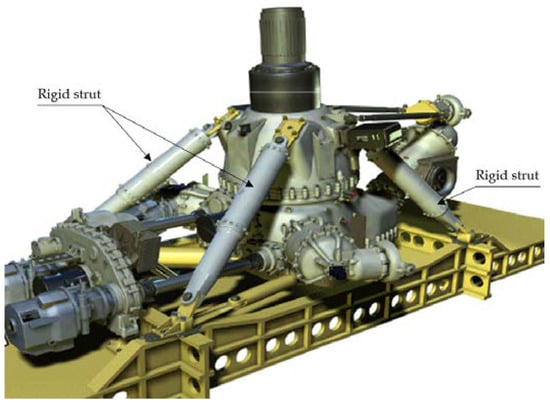
Figure 1.
Example of a rotor/gearbox assembly of a possible application, with indication of the supporting rigid struts to be replaced with the proposed ADVC.
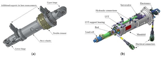
Figure 2.
The proposed active damper for vibration control (ADVC): (a) strut housing the EHSA (the external H/C compliant strut, which houses the EHSA and is part of the H/C design, was reproduced by a controlled stiffness metal strut, as shown in the figure, for laboratory tests and simulation purposes); (b) EHSA located inside the hollow strut.
The EHSA, depicted in Figure 2b, is hosted inside this compliant structure, with the cylinder connected to the lower hinge assembly and the rod to the upper hinge. The cylinder body is appositely designed to also carry out the function of the manifold of the system, connecting all the other elements. Figure 3 depicts a schematic representation of the main elements constituting the hydraulic circuit. The hydraulic cylinder is commanded by the electro-hydraulic servovalve (EHSV), which receives the electric reference signal from the embedded electronics.
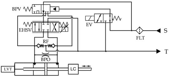
Figure 3.
Schematic representation of the EHSA.
The two chambers of the cylinder are connected through a bypass orifice (BPO), which always allows a small amount of fluid to leak between them; this allows the system to be more stable in the range of the null command and to avoid the possible hysteresis around the servovalve zero position. In real equipment, this calibrated resistance is realized by making a small puncture in the piston. This also has the effect of adding a small amount of extra damping to the system. The servovalve is connected to the supply pressure (S) through a filter (FLT) and two safety valves: the bypass valve (BPV) and the electrovalve (EV). The first is hydraulically actuated; therefore, if a drop in the supply pressure occurs, the valve closes under the action of its internal spring, isolating the system from the supply and connecting the two chambers, as shown in the bottom part of Figure 4. This means that the EHSA becomes transparent, with the strut fulfilling its structural support and, depending upon how it has been designed, providing its inherent passive damping contribution. The same scenario can occur if the electrovalve is intentionally commanded to put the actuator in bypass mode or if there is a fault in the electrical system, which causes the EV to deactivate. Two relief valves (RF) connect the two chambers to the return (T) to avoid overpressures. The system realizes a closed loop force control, using as feedback the direct force measurement obtained from the load cell (LC) mounted between the rod and its attachment to the upper hinge. The force command is not internally generated, but it comes from an external controller in charge of minimizing the fuselage vibrations commanding the four ADVCs. In addition, a linear velocity transceiver (LVT) is mounted in parallel to the cylinder and the rod to measure their relative velocity in order to help the control algorithm, e.g., allowing a feedforward branch to be added.
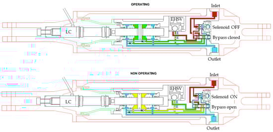
Figure 4.
Functional representation of the ADVC.
The parallel layout allows the EHSA size to be reduced as it becomes responsible only for the generation of the additional superimposing forces to suppress vibrations, while the static load is borne by the elastic structure.
3. Technical and Performance Specifications
The testing and acceptance procedure (ATP) document contains all of the tests that the ADVC must pass to be considered suitable for aircraft integration. In the first stage of the project, the technical specifications needed to make the system compliant with the ATP, listed in Table 1, were obtained by means of a model-based design approach, which involves a campaign of simulations with the dynamic model, as described in Section 4.

Table 1.
Technical and performance characteristics of the ADVC obtained from the design process.
The ATP was written for the selected reference application of a 15-seat medium-sized twin-engine helicopter with an estimated maximum take-off weight of 6000 kg. The combination of the number of blades and their rotational speed result in a vibratory disturbance at approximately 25 Hz on the cabin. The mass of the fuselage seen by every single strut was estimated to be 500 kg. Based on these macroscopic data, several tests were outlined in the ATP, starting with the basic ones (e.g., maximum pressure, leakage, and so forth), in accordance with the applicable safety standards, to those more specific for the considered application, aimed to verify and guarantee the desired performance of the ADVC.
The acceptance tests were defined to verify both static and dynamic characteristics, while the ADVC is mounted in a dedicated test bench, in which it is interposed between a fixed stimuli generator (an electrohydraulic position-controlled commercial servo-actuator) and a suspended mass of 500 kg. The concept of the test bench is also replicated in the mathematical model. Two static tests are foreseen to verify the stall load and the stiffness of the compliant structure. Three dynamic tests verify the actuator controllability and stability, the displacement transmissibility, and the ability of the ADVC to promptly react in a restricted amount of time to an impulsive disturbance, represented by a step displacement of the upper hinge. These tests will be described later in detail in Section 5.
4. Mathematical Model
The mathematical model was a key element of the design process as it helped to define the optimal characteristics of the internal components of the EHSA; it was used to test and verify the various hypotheses on both system configuration and single components’ sizes and performances. The model was used as a virtual test bench to perform the ATP tests and confirm the design choices. For this reason, it was built with the same concept as the real test bench that will be used to test the real ADVC, as shown in Figure 5.
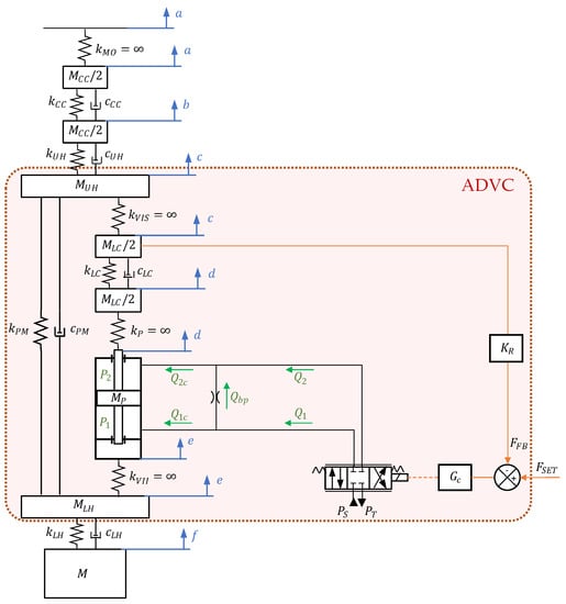
Figure 5.
Scheme of the mathematical model of the ADVC, mounted on the simulated test bench to perform ATP tests.
The model of the sole ADVC is represented by the block highlighted by the red rectangle in Figure 5, where the main elements can be observed with reference to Figure 3. The system is always simulated in normal operating mode; therefore, to speed up simulations, the bypass valve and the electrovalve were not considered. The system reflects the parallel structure, with the external compliant strut being represented by the spring-damper system (PM) on the left. The EHSA is represented by the hydraulic cylinder, the servovalve, the bypass orifice, and the controller. It is worth highlighting that the masses of the cylinder body (the manifold), the servovalve, the electronics, and the safety valves are lumped in the body of the lower hinge. Finally, the internal load cell is represented as a spring-damper system and half of its mass is attached to the piston body, while the other half is lumped into the upper hinge body. The mass is hung to the lower hinge and the upper hinge is connected, through an external load cell, to the stimuli actuator, which is not modeled and is represented directly with the imposed motion of the reference system . Therefore, the external inputs expected by the entire model are the force command signal of the EHSA; the displacement imposed by the upper actuator; and the operative test conditions, i.e., the oil temperature and supply and return pressure.
The model can be organized into three layers. The first layer is dedicated to the control and management of the model, containing all of the instructions regarding the simulation to be executed. From this layer, the user can define the type of simulation or ATP test to be run, the oil temperature, the average supply and return pressure, the intensity of the noise on acquired signals, and the servovalve current. The second layer holds the set of parameters needed by the model to represent the particular system under study, such as the geometric data, material information, and the properties and physical laws of the hydraulic oil. The latter are calculated as a function of the temperature and dispersed air percentage. The third layer represents the Simulink implementation, depicted in Figure 6, in which each subsystem corresponds to a physical component and the layout reflects the real architecture. The inputs and outputs of each subsystem also correspond to the physical quantities effectively exchanged between connected components.
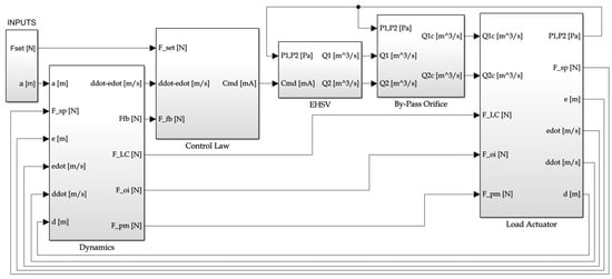
Figure 6.
Main screen of the Simulink mathematical model.
4.1. Electrohydraulic Servovalve (EHSV)
The servovalve was modeled reflecting the real characteristics of the component, following the approach presented in [42,43]. However, for simplicity, the first stage was represented with a grey-box second-order transfer function with hysteresis, dead band, and null bias, giving as output the position of the servovalve spool.
Subsequently, the control flows were calculated using the Wheatstone bridge analogy [44,45]; that is, the flows sent to the chambers ( and ) are obtained as the difference between the flows from the supply ( and ) and to the return ( and ):
The entity of each flow depends on the spool position, which opens or closes the flow passage sections. With seals being absent on the servovalve spool, a small amount of flow is always present, even when the spool completely covers the ducts, as leakage. Each flow component depends on the hydraulic resistance and pressure drop across it. Each hydraulic resistance is composed of a laminar () and a turbulent () component. The first represents the power loss associated with the passage of the fluid in the radial clearance between the spool and the sleeve (Figure 7). The second is associated with the discharge resistance in the presence of turbulent flow owing to the sharp edges of the spool.
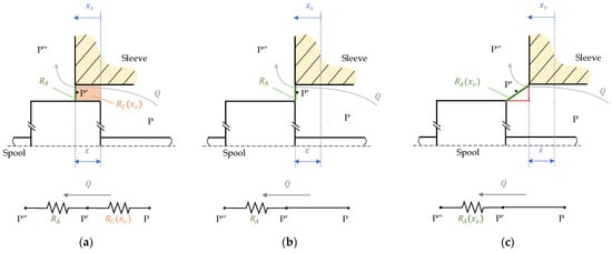
Figure 7.
Hydraulic resistances within the servovalve: (a) positive overlap; (b) zero overlap; and (c) negative overlap.
The spool continuously moves within the servovalve body (sleeve) as the input command coming from the controller varies in time. Figure 7 shows three particular conditions that can occur in each port during a simulation. Each time the spool position is lower than the design overlap ε, the scenario of Figure 7a applies. Figure 7a depicts the particular case in which the spool is in its null position and the system is designed with an overlap. Even if the spool closes the passage, a small amount of oil can pass in laminar conditions with small Raynolds’ numbers through the thin clearance created between the overlapping parts of the spool and the sleeve (the orange area in Figure 7a). At the hedges of this gap, a turbulent flow occurs. The system can then be modeled with the electrical equivalence of two resistances in series, and the flow results from the solution of the following second-order equation for the i-th port [46]:
When the spool moves, e.g., of a positive displacement , the laminar resistance varies as follows [46]:
where is the oil dynamic viscosity, is the design overlap, is the width of the spool port opening, and is the radial clearance. The sign depends on the considered port.
Each time the spool position is greater than the design overlap ε, the scenario of Figure 7c applies. In this situation, there is no more overlap between the spool and the sleeve (no orange area), thus the laminar flow disappears. Hence, the only resistance encountered by the fluid consists of a restricted section with sharp edges, represented by the turbulent term :
where is the section perpendicular to the oil path, approximated with the opening section going from the sleeve to the spool edges, as shown in Figure 7c. The area varies with , assuming a minimum of for critical or positive overlap conditions (Figure 7a,b). The discharge coefficient is a function of the Reynolds number and of the geometrical characteristics of the ports [42]. The limit situation representing the transition scenario between the two previously explained conditions is that represented in Figure 7b, i.e., when equals the design overlap ε. In this case, there is no overlap area between the spool and the sleeve (no orange area in Figure 7b), and the restricted area of the turbulent flow resistance assumes its minimum value .
4.2. Bypass Orifice
The flow rates that effectively contribute to an increase in the actuator chamber pressures are the net flow rates considering the presence of the bypass. In fact, they can be calculated as follows:
The bypass is modeled as a generic orifice, thus the flow between the chambers can be expressed as follows [45]:
where and are the oil pressures in the chambers; is the orifice passage area; is the oil density; and is the discharge coefficient, dependent on the Reynolds’ number according to [47].
4.3. Actuator
The hydraulic cylinder is modeled as a lumped parameter system in which both the piston and the cylinder have a single translational degree of freedom in the vertical direction; the coordinates describing their motion are and , respectively, according to Figure 5. The motion of the piston can be obtained from the following equation of motion:
where and are the masses of the piston and of the internal load cell, respectively; is the piston effective area; is the gravity acceleration; and is the interaction force with the ADVC upper hinge coming from the internal load cell, expressed as follows:
where and are the stiffness and damping factor, respectively, of the load cell.
The friction coefficient between the cylinder and the piston is computed according to [48], considering the geometric dimensions of the sealings and their squeeze depending on the pressure drop across them. The obtained values were used to calculate the equivalent friction force by means of a modified LuGre friction model [49]; this approach allows obtaining the friction force as a function of the rod/cylinder relative motion, starting only from their relative speed, maintaining and as absolute coordinate systems.
The pressures in the actuator chambers can be calculated by applying the mass continuity equation to the volumes of the chambers:
where is the oil bulk modulus; is the chamber volume; is the relative displacement between the rod and its housing; is the leakage between the chambers and the return; and is the internal leakage between the two chambers, calculated as the sum of the Couette flow determined by the oil entrainment during piston movement with the flow through a series of laminar and turbulent resistances, modeling the flow through the sealing element and the cylinder as well as the permeability of the seal according to [48,50].
The motion of the cylinder is described by the following equation:
where is the masses of the lower hinge, the cylinder, and all of the other components integral to the manifold and is the force transmitted to the ADVC through the lower hinge by the mass due to inertial loads:
where and are the stiffness and damping factor, respectively, of the lower hinge joint.
The force given by the compliant structure is also represented as a spring-damper action between the upper and lower hinges:
as well as that exchanged between the upper hinge and the external auxiliary load cell:
and that between the input actuator imposed position and the external load cell:
The displacement of the inertial mass is obtained by a simple equation of motion of a mass-spring-damper system with the addition of the friction force with the linear guides of the test bench.
4.4. Electronic Control Unit
The embedded electronics perform the closed loop force control, taking as feedback the force measured by the internal load cell mounted between the rod and the upper hinge. This control is modelled with a PI compensator with output saturation and clamping anti-windup. The input signals are corrupted with Gaussian random noise to simulate electromagnetic disturbances. The model considers a discrete controller, thus value and time discretization are applied, while a transport delay is added to the output to take into consideration the processing time, an aspect that becomes relevant in force control systems with high bandwidth. The signal coming from the LVT is currently not yet used, but it will be integrated into the control scheme in a future implementation.
5. Results and Preliminary Design Validation
The mathematical model has undergone ATP tests to verify the compliance of the designed system with the expected performance. As previously introduced, the ATP test reproduced with the dynamic model can be subdivided into two main categories: the static and dynamic tests. The first type aims to test the static characteristics of the two main elements, i.e., the EHSA stall load and the stiffness of the external housing, while the objective of the second typology is to verify the performance of the entire ADVC in dynamic conditions; that is, analyzing its ability to react to external disturbances and to suppress vibrations. Additionally, the ATP specifies a set of tests to be performed on the real equipment that are not considered in this paper because we aimed to test the structural resistance and proper assembly process of the ADVC, which are assumed to be ideal in the mathematical model. These tests include a physical inspection; the functionality check of the bypass and electrovalves; and the verification of leakage and seal, of the maximum pressure, of the null bias, and of the power drawn by the servovalve. In this section, the obtained results are shown and commented on in order to validate the design and to show the capabilities of the proposed active damper. The model was created in the MATLAB Simulink environment and each simulation was carried out using the ode14x fixed step solver with an integration time step of .
5.1. Stall Load Test
The first static test is the verification of the stall load. During the test duration, the stimuli actuator (represented by the coordinate in Figure 5) is kept steady, which means .
The test procedure involves a slow ramp of the force request up to 125% of the theoretically expected stall load in compression, then the force set is brought back to a null value, and then again to 125% of the extension stall load. Finally, the test concludes by zeroing the command. Positive values of the force mean compression, while negative values stand for extension of the ADVC. The feedback comes from the internal load cell, depicted with the dashed line in Figure 8. The test is considered passed if the stall load in both directions exceeds 97.5% of the theoretical value; in this case, it must be greater than 19,500 N, with the theoretical stall load being 20 kN.
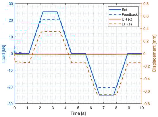
Figure 8.
Stall load test; blue lines represent the set and feedback forces, while the orange lines are the displacement of the lower (LH) and upper (UH) hinges of the ADVC.
Figure 8 depicts the positive results of the test performed with the model, showing that, following the request of 25 kN, the ADVC is able to give as output a stall load of 20,350 N and −20,388 N for compression and extension, respectively.
The figure also shows the displacement of the upper hinge (UH) and lower hinge (LH); as the simulation starts from a non-equilibrium condition, during the first instants, gravity causes the mass to drop with a consequent small extension of the ADVC and sudden reaction in the force of the EHSA. Referring to Figure 5, the upper hinge is connected to the stimuli actuator through an external load cell, which presents a very high stiffness; therefore, the UH signal remains almost steady. When the force command is imposed on the EHSA, basically only the LH moves, according to the sign convention of Figure 5 (positive upwards displacement).
5.2. Compliant Structure’s Stiffness Test
The second static test is the verification of the stiffness of the external housing. During the entire test duration, the stimuli actuator is kept steady, that is, .
The test procedure is similar to the previous one; it involves a slow ramp of the force request up to 50% of the theoretical stall load in compression (i.e., 10 kN), then the force set is brought back to a null value, and then to the same value of 10 kN in the other direction. Finally, the test concludes by zeroing the command. The test is considered passed if the measured housing stiffness, in both compression and extension cases, is within the range of of the theoretical value (i.e., ), which means it must lie between and . The force and relative displacements of the upper and lower hinges are measured by the internal load cell and by two lasers pointing to the two appendices attached to both hinges, respectively, for test purposes (shown in Figure 2). For the latter measurement, in the model, the physical coordinates and are used directly.
Figure 9 depicts the successful result of the test performed with the model. The force levels and relative displacements of the hinges are measured in the central point of the two flat force segments at . According to the results listed in Table 2, the ADVC passed the test with stiffness values of and for extension and compression, respectively.
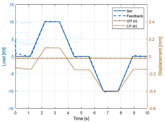
Figure 9.
Stiffness test; blue lines represent the set and feedback forces, while the orange lines are the displacement of the lower (LH) and upper (UH) hinges of the ADVC.
Table 2.
Results of the static test aimed to measure the stiffness of the external housing.
As in the previous test, the upper hinge remains steady as the stimuli actuator is not moving, while the lower hinge varies its position according to the force generated by the EHSA. The small deviation in the force between compression and extension can be ascribed to the presence of friction both between the rod and the cylinder of the EHSA and between the hung mass and its vertical guides.
5.3. Actuator Controllability
The first dynamic test is the verification of the controllability of the force generated within the ADVC. The objective of this analysis is to check the system bandwidth when the mass of 500 kg is attached. During the entire test duration, the stimuli actuator is kept steady, that is, .
The test procedure consists of applying a sinusoidal force command with a frequency of 25 Hz and an amplitude of 14 kN; the test is considered passed if the amplitude of the force read by the internal load cell is attenuated less than 3 dB with respect to those of the input and, concurrently, the phase delay remains smaller than 90°.
From the results of the test, depicted in Figure 10, the force attenuation is , compatible with the prescribed limits, with a phase delay of . The displacement of the lower hinge follows the generated force, as expected. It can also be observed that, contrary to the static tests, the position of the upper hinge moves under the action of the EHSA force because of the presence of the elasticity of the external load cell and of the hinge itself (according to the model scheme in Figure 5). In fact, because of the presence of a large amount of inertia attached to the lower hinge, the high-frequency load generated by the ADVC pushes upwards the upper hinge as well.
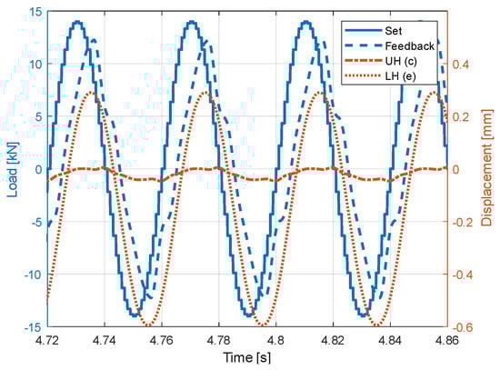
Figure 10.
Controllability test; blue lines represent the set and feedback forces, while the orange lines are the displacement of the lower (LH) and upper (UH) hinges of the ADVC.
5.4. Frequency Response of the System with the Hung Mass
As a natural progression of the previous analysis, this paragraph presents the results of a non-linear frequency response of the ADVC, considering the force control in both the open loop and closed loop for three different amplitudes. Each dot of the graphs shown in Figure 11 is extracted from a single simulation of the system with a fixed steady position of the stimuli actuator and a sinusoidal force command imposed on the EHSA. As the model is non-linear, the magnitudes of the Bode diagrams are not the same for the different input amplitudes; as expected, as the requested force increases, the system struggles to follow it, thus lowering the closed loop characteristic, slightly reducing the bandwidth.
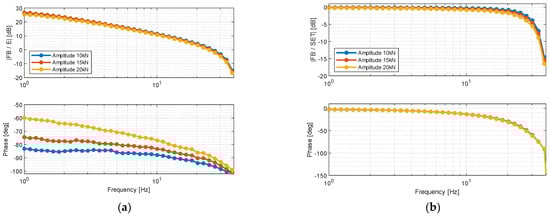
Figure 11.
Frequency response of the ADVC mounted on the ATP dedicated test bench: (a) open loop and (b) closed loop.
From Figure 11b, it can be seen that the force control bandwidths (i.e., the frequency at which the closed loop response crosses −3 dB) of the ADVC with the hung mass for amplitudes of 20, 15, and 10 kN are 26, 27, and 28.4 Hz, respectively, coherent with the results obtained from the controllability test. Analyzing the open loop plot, it is possible to obtain the stability margins; in particular, for the current configuration, they resulted in a gain margin of 17 dB and a phase margin of 92°, showing a certain safety factor of the designed control strategy against instability.
5.5. Displacement Transmissibility
The second dynamic test is the first that includes the stimuli actuator; it is used to impose a sinusoidal motion (shown in Figure 12 in green) at 25 Hz with an amplitude of 0.45 mm. The model considers a delay between the command imposed on the stimuli actuator and its actual motion, assumed equal to 8 ms; for this reason, Figure 12 shows both the command (dashed green) and the effective motion observed by the model (solid green line). To maximize the figure readability, the convention of all of the displacement signals was inverted with respect to those shown in Figure 5, resulting in downward positive displacements. The goal of the test is to command the ADVC in such a way as to minimize the displacement of the lower hinge, i.e., of the mass. The outcome is considered positive if the displacement amplitude attenuation is greater than 6 dB and if the phase delay between the displacement of the stimuli actuator and the lower hinge is lower than 70°.
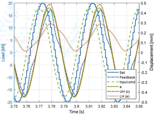
Figure 12.
Displacement transmissibility test. To maximize the figure readability, the convention of all of the displacement signals was inverted with respect to those shown in Figure 5, resulting in downward positive displacements.
To fulfill this task, the actuator is commanded with a sinusoidal force set with an amplitude of 20 kN and the same frequency of the disturbance, i.e., 25 Hz, and with a phase delay such that the actual generated force becomes phased with the external displacement input. It can be seen from Figure 12 that this approach sensibly reduces the oscillations of the lower hinge, with an attenuation of and a transmissibility phase delay of .
This test is aimed to demonstrate the ADVC capabilities, which can be exploited by the H/C designer, which, however, will be in charge of the control algorithm that generates the force set for the ADVC to suppress vibrations. During the ADVC ATP test, only a force control can be performed, thus this test follows an open loop approach to reduce the mass vibration.
5.6. Response to a Step Disturbance
The last dynamic test of the ATP consists of the verification of the ability of the ADVC to rapidly reject external disturbances. The procedure involves commanding a null force input to impose a step disturbance of 0.45 mm with the stimuli generator (orange in Figure 13), measuring the time spent by the ADVC to bring the force (blue) back to the acceptable region of (shaded green area) within a specific amount of time, that is, 50 ms since the step appliance (red line in Figure 13). Actually, because ideal steps do not actually exist, they could not be applied by the real stimuli actuator; hence, the signal shown with the dashed line was imposed as coordinate in the model, corresponding to the step response of a first-order system with a time constant of 3.1 ms, coherent with the time delay assumed between the command and the actual displacement of the stimuli generator in the transmissibility test. To be conservative, 50 ms was calculated from the ideal step appliance, while they could be assumed to be calculated from the instant in which the actual displacement of the stimuli actuator reaches, for example, 90% of the step amplitude.
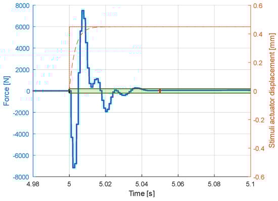
Figure 13.
Response to a step disturbance of 0.45 mm (in orange); the force (in blue) has to enter the acceptability region (shaded green) within the time of 50 ms, indicated by the red line, from the step instant.
The simulation results show that the ADVC is able to quickly react to external disturbances and reject them in a reduced amount of time.
6. Conclusions
The main source of vibrations in helicopters is the main rotor/gearbox assembly. These vibrations drastically reduce the quality of flight perceived by cabin occupants and may shorten the life of onboard equipment.
To overcome this issue, one solution is to replace the rigid struts connecting the fuselage to the main rotor/gearbox assembly with active dampers. This paper presents the lightweight design proposed by Elettronica Aster S.p.A. that consists of a parallel nested arrangement of a compliant strut and an electrohydraulic servoactuator. This solution allows the static load to be borne by the compliant external structure without compromising the mechanical connection of the rotor with the cabin, offering a failsafe system by design. In such a way, the internal actuator has only the duty of generating an additional excitation force to suppress vibrations, allowing the system to reach high power densities. Furthermore, in the case of power loss of the internal active EHSA as well, the system is completely put in bypass and the structural response remains that of the supporting struts, whose configuration, given the limited dimensions of the EHSA, can be finely tailored by the H/C designer to better suit its needs. The system contains two safety valves to handle the situations of loss of both electric and fluid power. The generated force is directly measured by a miniaturized load cell installed on the actuator rod, with consequent low delay and high bandwidth of the force-controlled system. Moreover, an LVT is mounted in parallel with the rod and the cylinder of the EHSA to allow their relative speed measures to enhance the system control.
In the first stage of the research project, the architecture and components were chosen by means of a model-based design approach. For this reason, a detailed mathematical model is presented in the paper. The system was designed for the reference application of a 15-seat medium-sized twin-engine helicopter. The model of the system was also used to verify the compliance of the active damper with the strict requirements imposed by the chosen application. Therefore, the model structure reflected the real test bench setup, thus representing a testing digital twin also used to design the test rig to perform acceptance tests.
The results of the simulations showed that the designed system is able to meet the requirements and is thus ready to move to the following extensive certification stage. The Elettronica Aster’s active damper can reach stall loads >20 kN while maintaining an extremely low dry weight of 5 kg for the EHSA, which becomes 15.9 kg when it is installed in the compliant external strut manufactured for laboratory testing. Because this strut was made from aluminum alloys and stainless steel, whereas in the actual H/C configuration, it is expected to be made in composite materials, the overall mass appears conservative for the representation of real applications. These values translate in a system with a power density of when the complete system is considered, while traditional solutions sit around [8].
The damper physical realization, test bench design, experimental campaign, certification, and ADVC and subcomponents’ model validation will be presented in Part 2.
Author Contributions
Conceptualization, A.C.B., M.G., P.G.P. and S.S.; methodology, A.C.B.; software, A.C.B.; validation, A.C.B. and S.S.; formal analysis, A.C.B. and S.S.; investigation, A.C.B. and S.S.; resources, A.C.B.; data curation, A.C.B.; writing—original draft preparation, A.C.B.; writing—review and editing, A.C.B., M.G., S.S., P.G.P. and M.S.; visualization, A.C.B.; supervision, P.G.P. and M.S.; project administration, S.S., P.G.P. and M.S.; funding acquisition, P.G.P. and M.S. All authors have read and agreed to the published version of the manuscript.
Funding
This research was partially funded by the Italian Ministry of Defense under the National Programme for Military Research (PNRM), grant number n° 806 di Rep. del 04.05.2016.
Data Availability Statement
Data sharing is not applicable to this article.
Conflicts of Interest
The authors declare no conflict of interest.
References
- Krysinski, T.; Malburet, F. Mechanical Vibrations—Active and Passive Control, 2nd ed.; ISTE Ltd.: London, UK, 2021; ISBN 9781905209293. [Google Scholar]
- Tamer, A.; Muscarello, V.; Masarati, P.; Quaranta, G. Evaluation of Vibration Reduction Devices for Helicopter Ride Quality Improvement. Aerosp. Sci. Technol. 2019, 95, 105456. [Google Scholar] [CrossRef]
- Delcor, L.; Parizet, E.; Ganivet-Ouzeneau, J.; Caillet, J. Model of Sound and Vibration Discomfort in Helicopter Cabins. Appl. Acoust. 2022, 195, 108847. [Google Scholar] [CrossRef]
- Harrer, K.L.; Yniguez, D.; Majar, M.; Ellenbecker, D.; Estrada, N.; Geiger, M. Whole Body Vibration Exposure for MH-60S Pilots. In Proceedings of the Forty Third Annual SAFE Association Symposium, Salt Lake City, UT, USA, 13–16 May 2005. [Google Scholar]
- Paul, W.F.; Mard, K.C. Vibration Damped Helicopter Rotor. U.S. Patent 3540809, 17 November 1970. [Google Scholar]
- Wachs, M.A. The Main Rotor Bifilar Absorber and Its Effect on Helicopter Reliability/Maintainability. SAE Tech. Pap. 1973, 82, 2972–2981. [Google Scholar] [CrossRef]
- Frahm, H. Device for Damping Vibrations of Bodies. U.S. Patent 989958, 18 April 1911. [Google Scholar]
- Welsh, W.A. Helicopter Vibration Reduction. In Morphing Wing Technologies: Large Commercial Aircraft and Civil Helicopters; Elsevier Ltd.: Stratford, CT, USA, 2018; pp. 865–892. ISBN 9780081009642. [Google Scholar]
- Ferris, D.L.; Smith, G.A. Helicopter Rotor Lead-Lag Damper. U.S. Patent 4105365, 8 August 1978. [Google Scholar]
- Lee, C.M.; Goverdovskiy, V.N.; Sotenko, A.V. Helicopter Vibration Isolation: Design Approach and Test Results. J. Sound Vib. 2016, 366, 15–26. [Google Scholar] [CrossRef]
- Jolly, M.R.; Rossetti, D.J.; Norris, M.A.; Miller, L.R. Hybrid Active-Passive Noise and Vibration Control System for Aircraft. U.S. Patent 5845236, 1 December 1996. [Google Scholar]
- Flannelly, W.G. Dynamic Antiresonant Vibration Isolator. U.S. Patent 3322379, 30 May 1967. [Google Scholar]
- Braun, D. Development of Antiresonance Force Isolators for Helicopter Vibration Reduction. J. Am. Helicopter Soc. 1982, 27, 37–44. [Google Scholar] [CrossRef]
- Riedel, K. Vibration Analysis and Testing of Bell 429 Helicopter. In Proceedings of the American Helicopter 66th Annual Forum, Phoenix, AZ, USA, 11–13 May 2010; American Helicopter Society International: Phoenix, AZ, USA, 2010. [Google Scholar]
- Hege, P.; Genoux, G. The Sarib Vibration Absorber. In Proceedings of the Ninth European Rotorcraft and Powered Lift Aircraft Forum, Stresa, Italy, 13–15 September 1983. [Google Scholar]
- Cresap, W.L.; Myers, A.W.; Viswanathan, S.P. Pylon Mounting System for Reducing Helicopter Vibration. U.S. Patent 4362281, 7 December 1982. [Google Scholar]
- Griffin, M.D.; Hendricks, M.W. Helicopter Transmission Mount System. U.S. Patent 9254914, 9 February 2015. [Google Scholar]
- Wang, F.; Lu, Y.; Lee, H.P.; Ma, X. Vibration and Noise Attenuation Performance of Compounded Periodic Struts for Helicopter Gearbox System. J. Sound Vib. 2019, 458, 407–425. [Google Scholar] [CrossRef]
- Pearson, J.T.; Goodall, R.M.; Lyndon, I. Active Control of Helicopter Vibration. Comput. Control Eng. J. 1994, 5, 277–284. [Google Scholar] [CrossRef]
- Lyu, W.L. Method for Eliminating Aerodynamic Lift Vibration of Rigid Rotor Helicopters Based on the Novel Sine-Trim Model. Aerosp. Sci. Technol. 2020, 98, 105655. [Google Scholar] [CrossRef]
- Mura, R.; Lovera, M. Baseline Vibration Attenuation in Helicopters: Robust MIMO-HHC Control; IFAC: New York, NY, USA, 2014; Volume 19, ISBN 9783902823625. [Google Scholar]
- Yang, R.; Gao, Y.; Wang, H.; Ni, X. Reducing Helicopter Vibration Loads by Individual Blade Control with Genetic Algorithm. Machines 2022, 10, 479. [Google Scholar] [CrossRef]
- Millott, T.; Friedmann, P. Vibration Reduction in Helicopter Rotors Using an Actively Controlled Partial Span Trailing Edge Flap Located on the Blade. Nasa Contractor Report, 1 June 1994; Volume 4611, 19940031916. [Google Scholar]
- Zhou, Z.X.; Huang, X.C.; Tian, J.J.; Hua, H.X.; Tang, M.; Wang, C. Numerical and Experimental Analysis on the Helicopter Rotor Dynamic Load Controlled by the Actively Trailing Edge Flap. Smart Mater. Struct. 2022, 31, 035023. [Google Scholar] [CrossRef]
- Viswamurthy, S.R.; Ganguli, R. Performance Sensitivity of Helicopter Global and Local Optimal Harmonic Vibration Controller. Comput. Math. Appl. 2008, 56, 2468–2480. [Google Scholar] [CrossRef]
- Gianfranceschi, M.; Jacazio, G.; Wang, J. High Bandwidth Electromechanical Actuator for Swashplateless Blade Control System. In Proceedings of the 6th International Conference on Recent Advances in Aerospace Actuation Systems and Components, Toulouse, France, 2–3 April 2014. [Google Scholar]
- Wang, J.; Wang, H.; Wu, C. Development of Swashplateless Helicopter Blade Pitch Control System Using the Limited Angle Direct-Drive Motor (LADDM). Chinese J. Aeronaut. 2015, 28, 1416–1425. [Google Scholar] [CrossRef]
- Kakaley, D.E.; Jolly, M.R.; Buckner, G.D. An Offset Hub Active Vibration Control System for Mitigating Helicopter Vibrations during Power Loss: Simulation and Experimental Demonstration. Aerosp. Sci. Technol. 2018, 77, 610–625. [Google Scholar] [CrossRef]
- Kim, D.H.; Kwak, D.I.; Song, Q. Demonstration of Active Vibration Control System on a Korean Utility Helicopter. Int. J. Aeronaut. Sp. Sci. 2019, 20, 249–259. [Google Scholar] [CrossRef]
- Swanson, D.; Black, P.; Girondin, V.; Bachmeyer, P.; Jolly, M. Active Vibration Control Using Circular Force Generators. In Proceedings of the 41st European Rotorcraft Forum 2015, ERF 2015, Munich, Germany, 1–4 September 2015; Volume 1, pp. 627–637. [Google Scholar]
- Lang, K.; Xia, P.; Shang, L. New Algorithm and Experiments for Helicopter Active Control of Structural Response. J. Aircr. 2022, 59, 1152–1161. [Google Scholar] [CrossRef]
- Duc, D.H.; Mura, R.; Piroddi, L.; Lovera, M.; Luca Ghiringhelli, G. Robust Harmonic Control: An Application to Structural Vibration Reduction in Helicopters. IFAC-PapersOnLine 2015, 28, 263–268. [Google Scholar] [CrossRef]
- Konstanzer, P.; Enenkl, B.; Aubourg, P.A.; Cranga, P. Recent Advances in Eurocopter’s Passive and Active Vibration Control. Annu. Forum Proc. AHS Int. 2008, 1, 854–871. [Google Scholar]
- Shivashankar, P.; Gopalakrishnan, S. Review on the Use of Piezoelectric Materials for Active Vibration, Noise, and Flow Control. Smart Mater. Struct. 2020, 29, 053001. [Google Scholar] [CrossRef]
- Lang, K.; Xia, P. Hybrid Active Vibration Control of Helicopter Fuselage Driven by Piezoelectric Stack Actuators. J. Aircr. 2019, 56, 719–729. [Google Scholar] [CrossRef]
- Meng, D.; Xia, P.; Lang, K.; Smith, E.C.; Rahn, C.D. Neural Network Based Hysteresis Compensation of Piezoelectric Stack Actuator Driven Active Control of Helicopter Vibration. Sens. Actuators A Phys. 2020, 302, 111809. [Google Scholar] [CrossRef]
- Arcara, P.; Bittanti, S.; Lovera, M. Periodic Control of Helicopter Rotors for Attenuation of Vibrations in Forward Flight. IEEE Trans. Control. Syst. Technol. 2000, 8, 883–894. [Google Scholar] [CrossRef]
- Qin, Y.; Lu, Y.; Ma, J.; Yue, H. Active Vibration Control of Helicopter Maneuvering Flight Using Feedforward-Robust Hybrid Control Based on Reference Signal Reconstruction. Shock Vib. 2021, 2021, 3153531. [Google Scholar] [CrossRef]
- King, S.P.; Hughes, C.I. Method and Apparatus for Reducing Vibration of a Helicopter Fuselage. U.S. Patent No. 4819182, 4 April 1989. [Google Scholar]
- Staple, A.E.; Wells, D.M. The Development and Testing of an Active Control of Structural Response System for the EH101 Helicopter. In Proceedings of the 16th European Rotorcraft Forum, London, UK, 1 January 1990. [Google Scholar]
- Mcguire, D.; Miller, L.R.; Jolly, M.R.; Badre-Alam, A. Helicopter Reduced Vibration Isolator Axial Support Strut. U.S. Patent No. 8113321, 14 February 2007. [Google Scholar]
- De Martin, A.; Jacazio, G.; Dellacasa, A.; Sorli, M. High-Fidelity Model of Electro-Hydraulic Actuators for Primary Flight Control Systems. In Proceedings of the Bath/ASME Symposium on Fluid Power and Motion Control, Bath, UK, 12 September 2018; ASME: Bath, UK, 2018; pp. 1–8. [Google Scholar] [CrossRef]
- Ritter, O.; Wende, G.; Gentile, R.; Marino, F.; Bertolino, A.C.; Raviola, A. Intelligent Diagnostics for Aircraft Hydraulic Equipment. In Proceedings of the 4th European Conference of the Prognostics and Health Management Society, Utrecht, The Nederlands, 3–6 July 2018. [Google Scholar]
- Merrit, H.E. Hydraulic Control Systems; John Wiley & Sons, Inc.: New York, NY, USA; London, UK; Sydney, Australia, 1967; ISBN 0471596175. [Google Scholar]
- Jelali, M.; Kroll, A. Hydraulic Servo-Systems: Modeling, Identification and Control; Springer-Verlag London Limited: London, UK, 2003; ISBN 978-1-4471-0099-7. [Google Scholar]
- Van Schothorst, G. Modelling of Long-Stroke Hydraulic Servo-Systems; Mechanical Maritime and Materials Engineering: Delft, The Nederlands, 1997; ISBN 9037001610. [Google Scholar]
- Idelchik, I.E. Handbook of Hydraulic Resistance; Begell House Inc.: Moscow, Russia, 2007; ISBN 9781567002515. [Google Scholar]
- Bertolino, A.C.; Gentile, R.; Jacazio, G.; Marino, F.; Sorli, M. EHSA Primary Flight Controls Seals Wear Degradation Model. In Proceedings of the IMECE2018, Pittsburgh, PA, USA, 9–15 November 2018; ASME, Ed.; ASME: Pittsburgh, PA, USA, 2018; pp. 1–12. [Google Scholar]
- Andersson, S.; Söderberg, A.; Björklund, S. Friction Models for Sliding Dry, Boundary and Mixed Lubricated Contacts. Tribol. Int. 2007, 40, 580–587. [Google Scholar] [CrossRef]
- Bertolino, A.C.; De Martin, A.; Jacazio, G.; Sorli, M. A Case Study on the Detection and Prognosis of Internal Leakages in Electro-Hydraulic Flight Control Actuators. Actuators 2021, 10, 215. [Google Scholar] [CrossRef]


Disclaimer/Publisher’s Note: The statements, opinions and data contained in all publications are solely those of the individual author(s) and contributor(s) and not of MDPI and/or the editor(s). MDPI and/or the editor(s) disclaim responsibility for any injury to people or property resulting from any ideas, methods, instructions or products referred to in the content. |
© 2023 by the authors. Licensee MDPI, Basel, Switzerland. This article is an open access article distributed under the terms and conditions of the Creative Commons Attribution (CC BY) license (https://creativecommons.org/licenses/by/4.0/).