Article

Relief Mechanism of Segmented Hole Reaming and Stress Distribution Characteristics of Drilling Holes in Deep Coal Mine

1
School of Mines, China University of Mining & Technology, Xuzhou 221116, China
2
Coal Burst Research Center of China Jiangsu, Xuzhou Coal Mining Group, Xuzhou 221018, China
3
Zhangshuanglou Coal Mine, Xuzhou Coal Mining Group, Xuzhou 221018, China
*
Author to whom correspondence should be addressed.
Processes 2022, 10(8), 1566; https://doi.org/10.3390/pr10081566
Submission received: 16 June 2022 / Revised: 19 July 2022 / Accepted: 8 August 2022 / Published: 10 August 2022

Abstract

:
As the mining depth increases, in underground tunnels, caverns or pillar goaf, a rock burst is one of the important accidents that threaten mine safety. Drilling pressure relief becomes one of the main means of preventing rock bursts, which affect the mechanical properties and stability of the coal and rock in underground excavations. However, the surrounding rock of the roadway or the coal body is usually broken, and the pressure relief of the large-diameter borehole will affect its support. A segmented hole-reaming technology is proposed and applied in a coal mine in China. A pressure-relief mechanic model of segmented hole reaming was built. The coal sample had an elastic modulus of 0.35 GPa, the UCS and UTS were 17.4 MPa and 1.41 MPa, the Poisson ratio was 0.27, the cohesive force was 2.81 MPa, and the friction was 23.7°. The pressure relief range of the boreholes with different diameters, horizontal in situ stress coefficients, cohesive forces, and friction angles were analyzed. When the drill hole was increased from 120 mm to 200 mm, the pressure relief range was increased by 57.1%. The stress distribution of the staged reaming and pressure-relief drilling was also obtained. In the vertical direction, the vertical stress of the borehole first decreased and then was restored to the original rock stress area, and in the horizontal direction, it first increased and then was restored to the original rock stress area. A CMS1-6200 segmented drilling rig was used to construct the pressure relief hole. The weight of the drilled pulverized coal was monitored at different depths. The results showed that the amount of pulverized coal in all of the drilled holes was less than 3 kg/m, indicating that the effect of reducing the pressure relief is obvious. The study is of great significance to research the pressure relief range, mechanical characteristics and stress distribution of segmented hole reaming; it also provides insight into the rock burst prevention and the design of drilling in the mine site.

1. Introduction

The deep coal resources in China account for 53% of the proven coal resources. With the mining of long-term coal resources, the coal mining depth is extended at a speed of 10–25 m per year, and the average mining depth has reached 700 m [1]. The first problem faced by the deep coal resources is the high ground stress. The rocks have the characteristics of large deformations, significant rheological properties, and short dynamic responses under high stress. Therefore, the rock-burst prevention measures are the primary guarantee for safe production in the deep mines [2,3,4]. Drilling pressure relief has become one of the main means of preventing rock bursts [5,6,7]. The study points out that a larger borehole diameter has a better pressure relief effect [8]. However, the degree of the surrounding rock fragmentation is divided into a serious fragmentation zone, a moderate fragmentation zone, and a mild fragmentation zone [9], as shown in Figure 1. In a serious fragmentation zone, the pressure relief of the large-diameter borehole causes the surrounding rock of the roadway to be further broken, resulting in damage to the roadway support components and failure of the support. The expanding ratio in the rock is considered to be the most significant factor influencing the ultimate uplift resistance of the hole digging a foundation in rock [10]. In addition, the long-term stability and safety of underground excavations are closely related to the creep characteristics under different damage states [11]. Therefore, to reduce the damage of drilling to the surrounding rock and support body, and also to reduce the pressure in the deep coal-working face, the principle of variable-diameter pressure relief drilling is to implement small-diameter drilling in the serious fragmentation zone of the roadway’s surroundings and to expand the diameter of the drilled hole in the mild fragmentation zone of the roadway’s surrounding rock. In this way, the integrity and strength of the surrounding rock of the roadway can be guaranteed, and the pressure relief effect of the borehole can be guaranteed.
Drilling pressure relief has the advantages of a simple construction process, low-pressure relief cost, easy operation, and little impact on production. It is widely used in the prevention and control of rock bursts. The uniaxial compression test is used to investigate the interaction of two pre-existing cracks with an internal hole in some typical gypsum specimens in the laboratory. The fracture pattern and the failure mechanism of the specimens were analyzed [12,13]. The different configurations of the room and pillar under uniaxial loading were investigated [14]. Wang [15] proposed a new computational method to calculate the storage elastic-energy value of the surrounding rocks, based on numerical simulation and theoretical calculation. Ning [16] put forward that, when the energy reaches a certain level, the rock burst will occur. He [17] proposed a rock-burst proneness prediction method, based on rock digital drilling. Zhang [18] proposed the stress criterion and energy criterion for rock burst occurrence. The long borehole drilling was suggested before intense supporting measures are adopted to control the pressure. He [19] proposed a method of calculating the varied stresses induced by roof breakage in the support objects and coal bodies. The drilling pressure relief technology has become one of the important means of preventing rock bursts. The main research has formed theoretical achievements, such as the drilling pressure relief principle, pressure relief range, and impact evaluation criteria.
A segmented hole-reaming technology is proposed and applied in a coal mine in China. A pressure-relief mechanic model of segmented hole reaming was built. The pressure relief range of boreholes with different diameters, horizontal in situ stress coefficients, cohesive forces, and friction angles was analyzed. The stress distribution of staged reaming and pressure relief drilling was also obtained.

2. Engineering Background

2.1. General Situation of Working Face

Zhangshuanglou Coal Mine is located in Anguo Town, Xuzhou City, Jiangsu Province. The mine field area is about 37.8 km2, the strike length is 13.5 km, and the inclination length is 2.9 km. The grade of mine geological structure, the type of hydrogeological conditions, and the impact risk is medium.
The mainly mining coal layers are the seventh and ninth layers of the Shanxi Formation. There are two coal mining faces, namely the 74,104 working face and 9201 working face. The 74,104 working face is adjacent to the goaf of the 74,102 working face, and the north is close to the boundary of the mine field. The working face elevation is from −1060 to −1180 m, and the ground elevation is +37.1 m. The inclined length of the working face is 174.6 m and the strike length is 1180 m.

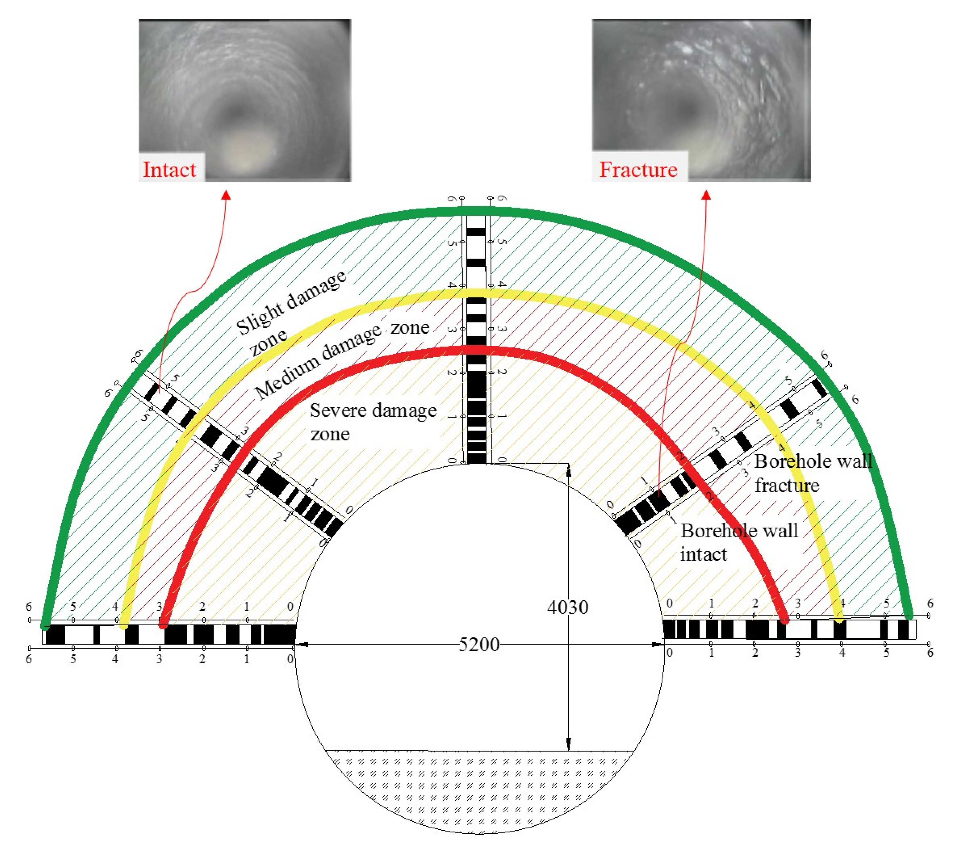
2.2. Experimental Method and Result

The samples were cored from intact coal from the 74,104 working face. The uniaxial compressive strength (UCS) and uniaxial tension strength (UTS) were tested, and the samples were cylinders with a diameter of 50 mm, a height of 100 mm, and prepared in accordance with the relevant experimental specifications recommended by the ISRM [20]. The studies have shown that the P-wave velocity is closely related to the strength of the rocks and is a good indicator of the different strength levels of the rock [21,22]. The P-wave velocity of the coal specimens was tested, and the specimens with P-wave velocities of 1630–1780 m/s were selected for the creep tests. The physical and mechanical properties of the coal samples were also obtained by the experimental test, as shown in Table 1. The coal sample had an elastic modulus of 0.35 GPa, the UCS and UTS were 17.4 MPa and 1.41 MPa, the Poisson ratio was 0.27, the cohesive force was 2.81 MPa, and the friction was 23.7°.

3. Pressure Relief Mechanical Model of Segmented Hole Reaming

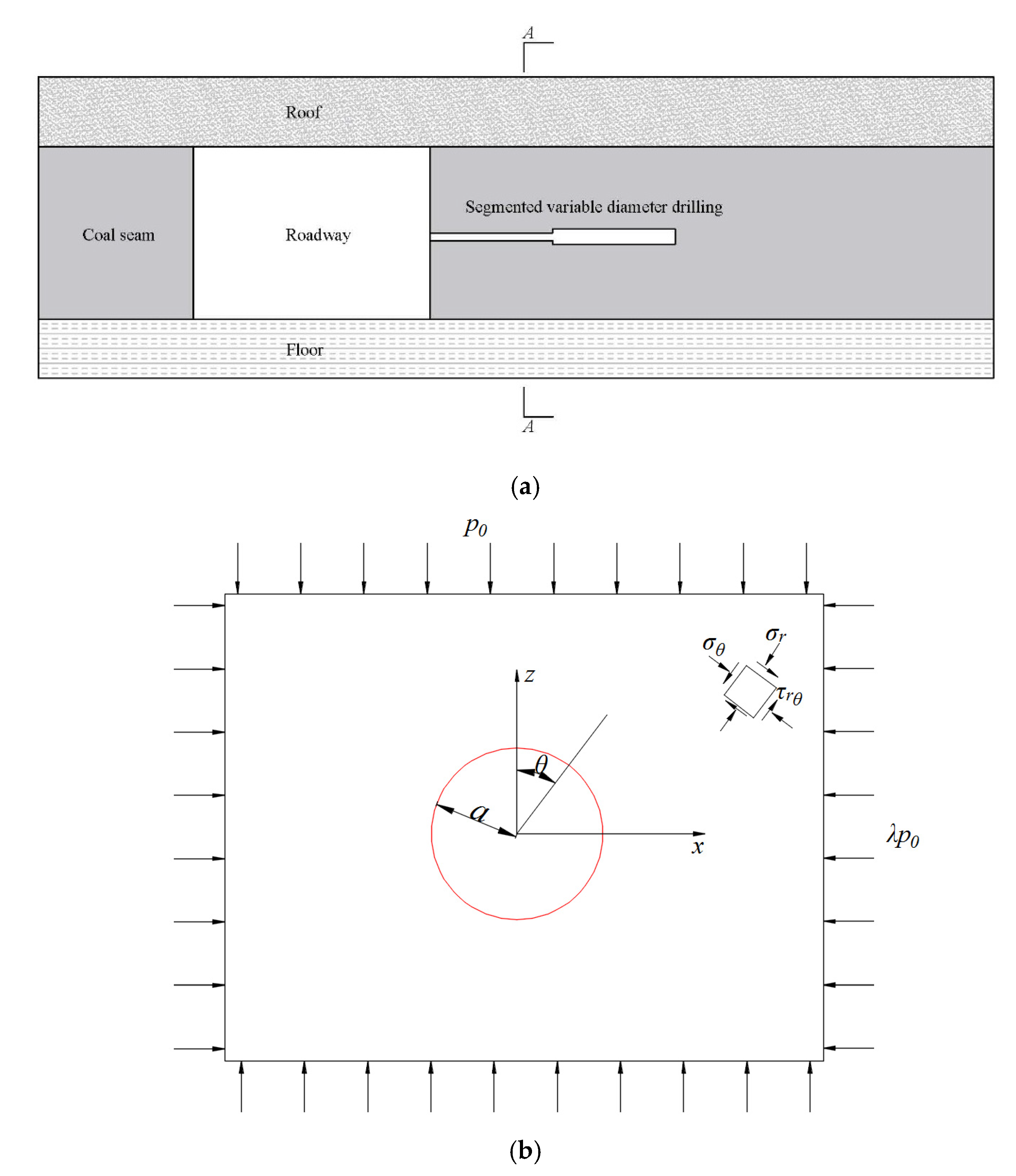
3.1. Pressure Relief Mechanical Model

Because the surrounding rock stress is a bidirectional unequal pressure, therefore the ratio of the bidirectional stress of the surrounding rock where the borehole is located is generally not equal to 1, so a bidirectional unequal pressure drilling mechanical model is established. The borehole radius is a, the vertical stress of the original rock is P0, and the lateral pressure coefficient is λ, as shown in Figure 2.

3.2. Solution of Pressure Relief Mechanic Model

Assuming that the surrounding rock mass is homogeneous and isotropic, the borehole section is round, and the burial depth and axial length are large enough. According to the superposition principle in elastic mechanics, the load is decomposed into the sum of the uniform pressure λ + 1 2 p 0 and the uniform pressure λ + 1 2 p 0 . When the four sides are uniformly distributed pressure λ + 1 2 p 0 , the stress component equation of the borehole surrounding rock in polar coordinates is [23]:
σ r = ( λ + 1 ) p 0 2 ( 1 a 2 r 2 ) σ θ = ( λ + 1 ) p 0 2 ( 1 + a 2 r 2 ) τ r θ = τ θ r = 0
When the four sides are uniformly distributed pressure λ + 1 2 p 0 , the stress component equation of the borehole surrounding rock in polar coordinates is:
σ r = ( λ + 1 ) p 0 2 ( 1 a 2 r 2 ) ( 1 3 a 2 r 2 ) cos 2 θ σ θ = ( λ + 1 ) p 0 2 ( 1 + 3 a 4 r 4 ) cos 2 θ τ r θ = ( λ + 1 ) p 0 2 ( 1 a 2 r 2 ) ( 1 + 3 a 2 r 2 ) sin 2 θ
By superimposing the stress components of the Formulas (1) and (2), the stress component of the polar borehole under the action of the bidirectional unequal compressive-stress field is obtained as:
σ r = ( 1 + λ ) P 0 2 ( 1 a 2 r 2 ) ( 1 λ ) P 0 2 ( 1 4 a 2 r 2 + 3 a 4 r 4 ) cos 2 θ σ θ = ( 1 + λ ) P 0 2 ( 1 + a 2 r 2 ) ( 1 λ ) P 0 2 ( 1 + 3 a 4 r 4 ) cos 2 θ τ r θ = ( 1 λ ) P 0 2 ( 1 + 2 a 2 r 2 3 a 4 r 4 ) sin 2 θ
The principal stress component at one point of the surrounding rock of the borehole in polar coordinates is:
σ 1 = σ r + σ θ 2 + 1 2 ( σ r σ θ ) 2 + 4 τ r θ 2 σ 3 = σ r + σ θ 2 1 2 ( σ r σ θ ) 2 + 4 τ r θ 2
The rock mass strength criterion can use the classic Mohr–Coulomb criterion, the formula is as follows:
σ 1 = 1 + sin φ 1 sin φ σ 3 + 2 C cos φ 1 sin φ
where the internal friction angle of the rock is φ; the single cohesion of the rock is C, MPa.
Putting Equation (5) into Equation (4), the yield equation of one point of the coal body around the borehole can be obtained as:
( σ r σ θ ) 2 + 4 τ r θ 2 = 2 C cos φ ( σ r + σ θ ) sin φ
Putting Equation (3) into Equation (6), the boundary line equation for the plastic failure of the surrounding rock of the borehole can be obtained as follows:
A R 2 a 2 + B R 4 a 4 + D R 6 a 6 + E R 8 a 8 = 9 ( 1 λ ) 2
where the R is the range of pressure relief area, m. The other parameters are as follows:
A = 6 ( 1 λ 2 ) cos 2 θ 12 ( 1 λ ) 2
B = ( 1 + λ ) 2 + 10 ( 1 λ ) 2 cos 2 2 θ 2 ( 1 λ ) 2 sin 2 2 θ 4 ( 1 λ 2 ) cos 2 θ 4 ( 1 λ ) 2 cos 2 2 θ sin 2 φ
D = 4 ( 1 λ ) 2 ( sin 2 2 θ cos 2 2 θ ) + 2 ( 1 λ 2 ) cos 2 θ 4 C r ( 1 λ ) 2 sin 2 φ cos 2 θ 4 ( 1 λ 2 ) cos 2 θ sin 2 φ
E = ( 1 λ ) 2 4 C 2 p 0 2 cos 2 φ ( 1 + λ ) 2 sin 2 φ 2 C p 0 ( 1 + λ ) sin 2 φ

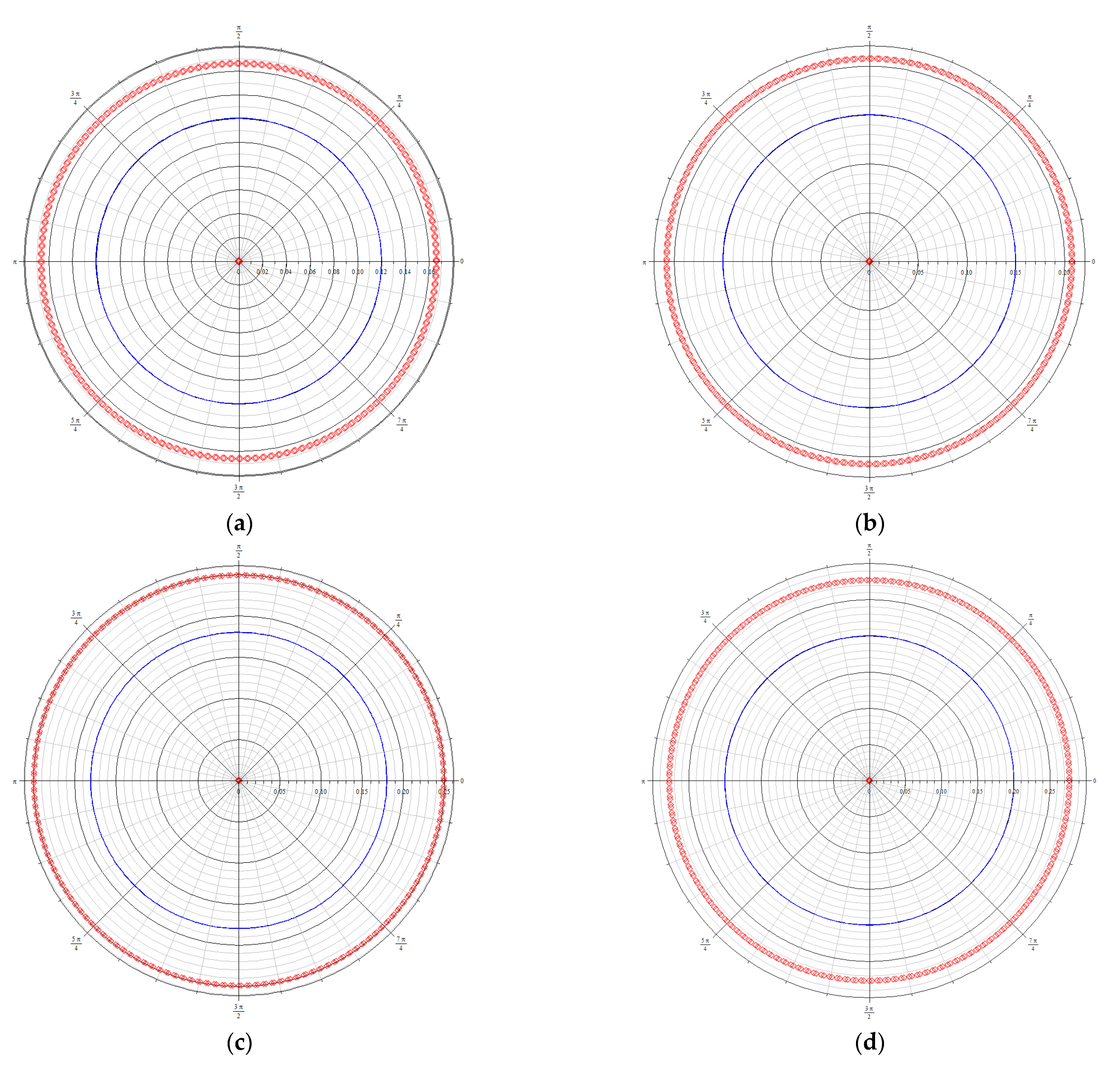
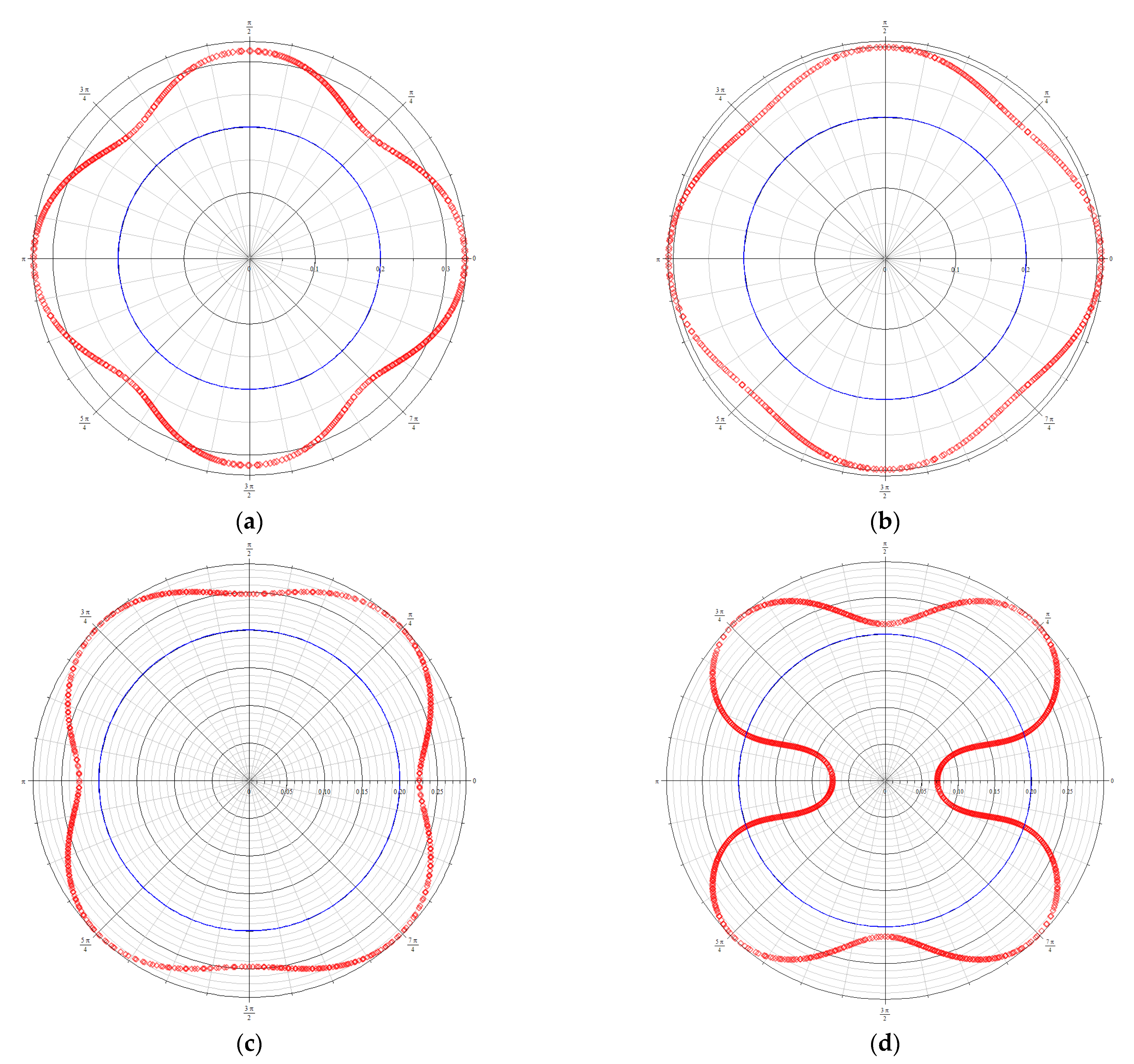
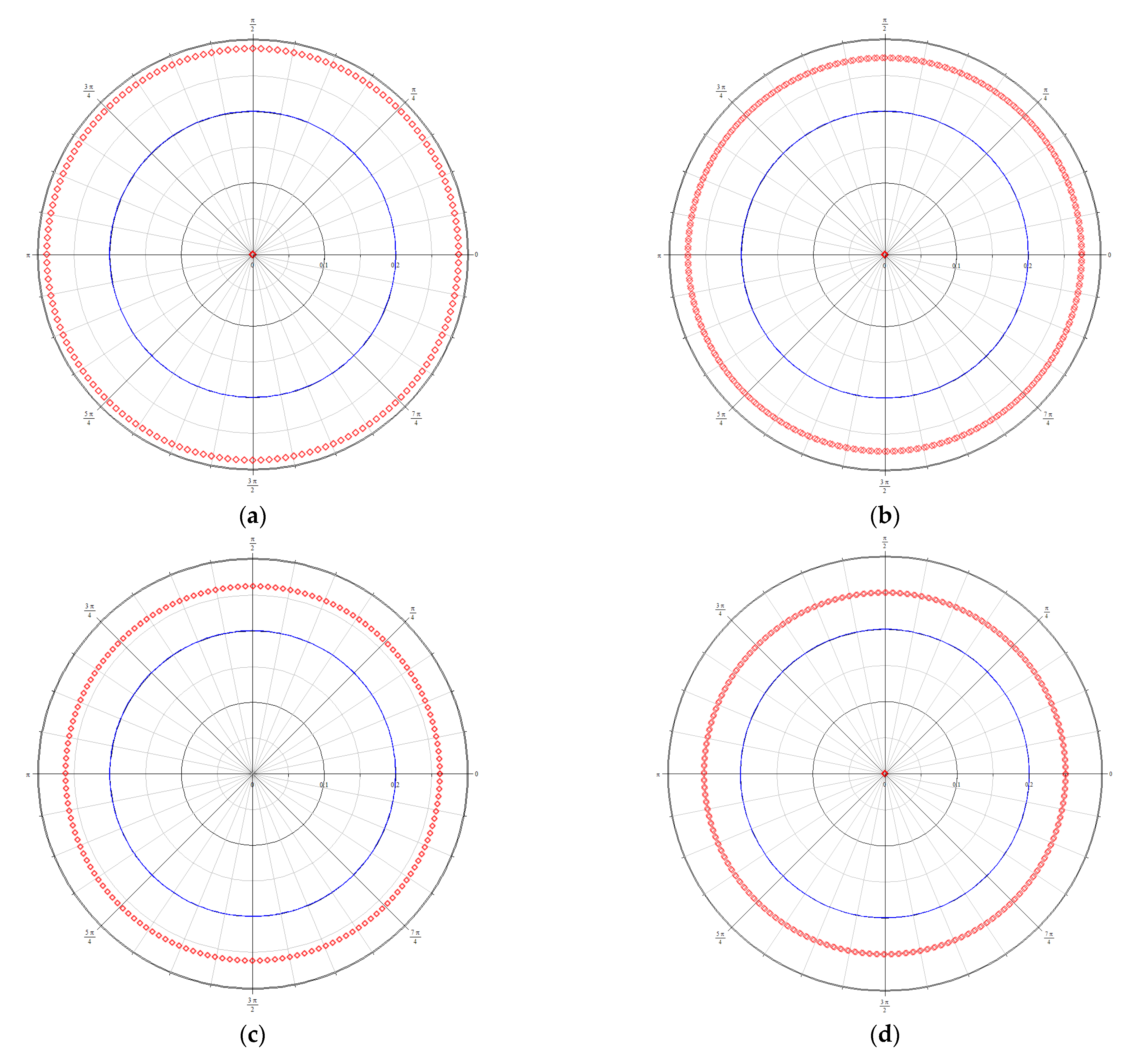
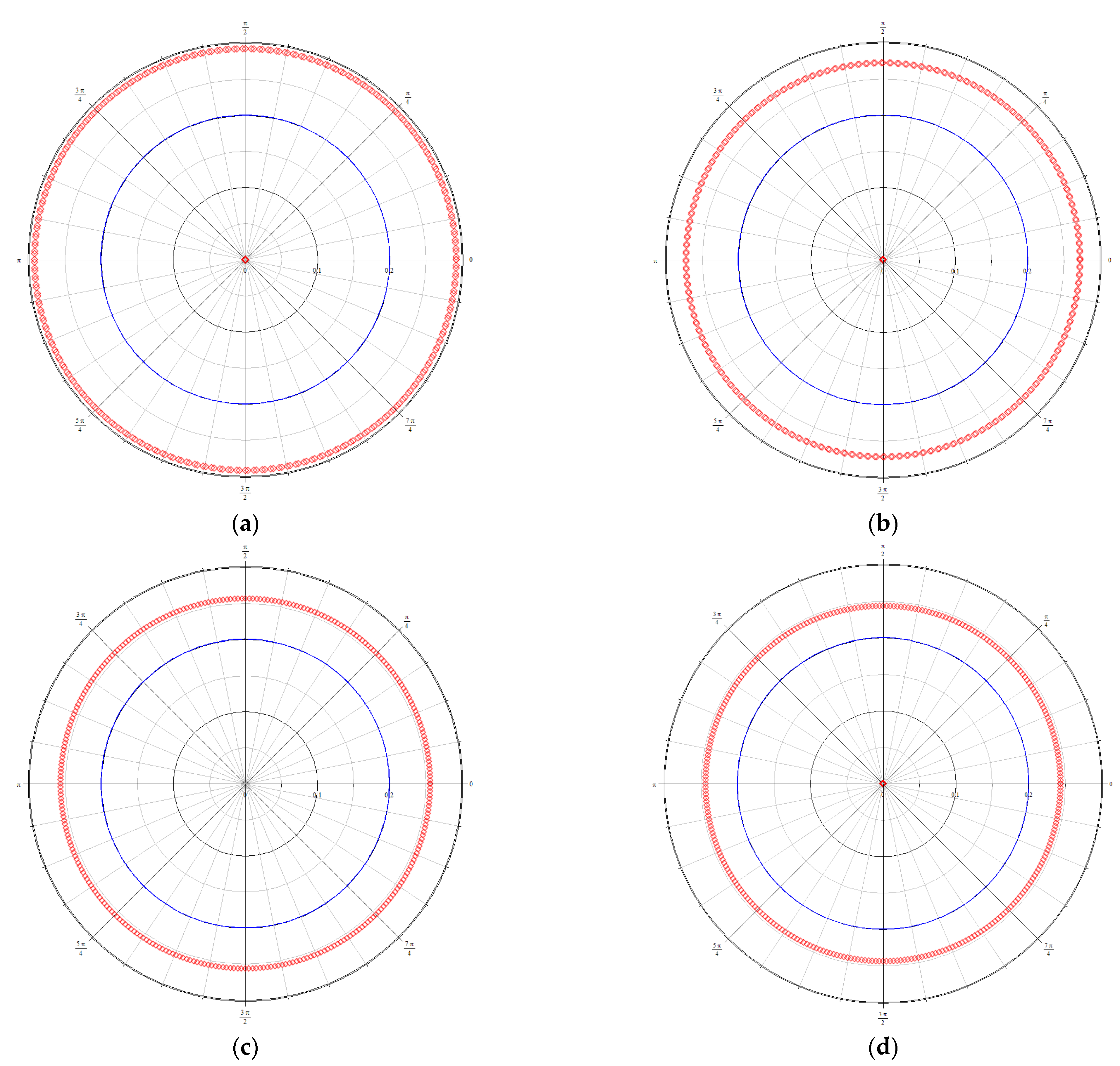
3.3. Pressure Relief Range

According to the basic geological conditions of the 74,104 working face in the Zhangshuanglou Coal Mine, the relevant parameters are put into the Formula (7). The damaged boundary line (red line) around the borehole under the different diameters (blue line) can be calculated as shown in Figure 3.
It can be seen from the pressure relief range of drilling holes with different diameters that the pressure relief range of different apertures presents a circular shape. With the increase in the borehole diameter, the pressure relief range gradually increases. When the drill hole is increased from 120 mm to 200 mm, the pressure relief range is increased by 57.1%. An elastoplastic model around the borehole considering plastic softening and dilatancy was established in the literature [24]. It is also pointed out that, with the increase in the borehole diameter, the pressure relief range is larger.
By putting different horizontal in situ stress coefficients into Equation (7), the damage boundary lines around the borehole under different in situ stress coefficients can be obtained, as shown in Figure 4.
From the range of borehole pressure relief under different horizontal in situ stress coefficients, it can be seen that the borehole pressure relief range with different horizontal in situ stress coefficients presents a “flower” shape. With the increase in the horizontal in situ stress coefficient, the pressure relief range gradually decreases. When the horizontal in situ stress coefficient increases from 0.8 to 1.2, the pressure relief range decreases by 12.4%.
Bringing different cohesive forces into Equation (7), the damage boundary lines around boreholes with different cohesion forces can be obtained, as shown in Figure 5.
It can be seen from the pressure relief range of drilling holes with different cohesion forces that the pressure relief range of the drilling holes with different cohesion forces is circular. With the increase in the horizontal in situ stress coefficient, the pressure relief range gradually decreases. When the cohesion increases from 3 Mpa to 6 Mpa, the pressure relief range decreases by 14.1%. The literature [25] analyzed the pressure relief effect of different coal body cohesion. The research showed that, when the cohesion of the coal body was smaller, the pressure relief range of the borehole was larger, which is consistent with the results of the paper.
Bringing different internal friction angles into Equation (7), the damaged boundary lines around the borehole with different internal friction angles can be obtained, as shown in Figure 6.
It can be seen, from the pressure relief range of drilling holes with different internal friction angles, that the pressure relief range of drilling holes with different internal friction angles is circular. With the increase in the internal friction angle, the pressure relief range gradually decreases. When the cohesion increases from 20° to 35°, the pressure relief range decreases by 16.3%.

4. Stress Distribution of Staged Reaming and Pressure Relief Drilling

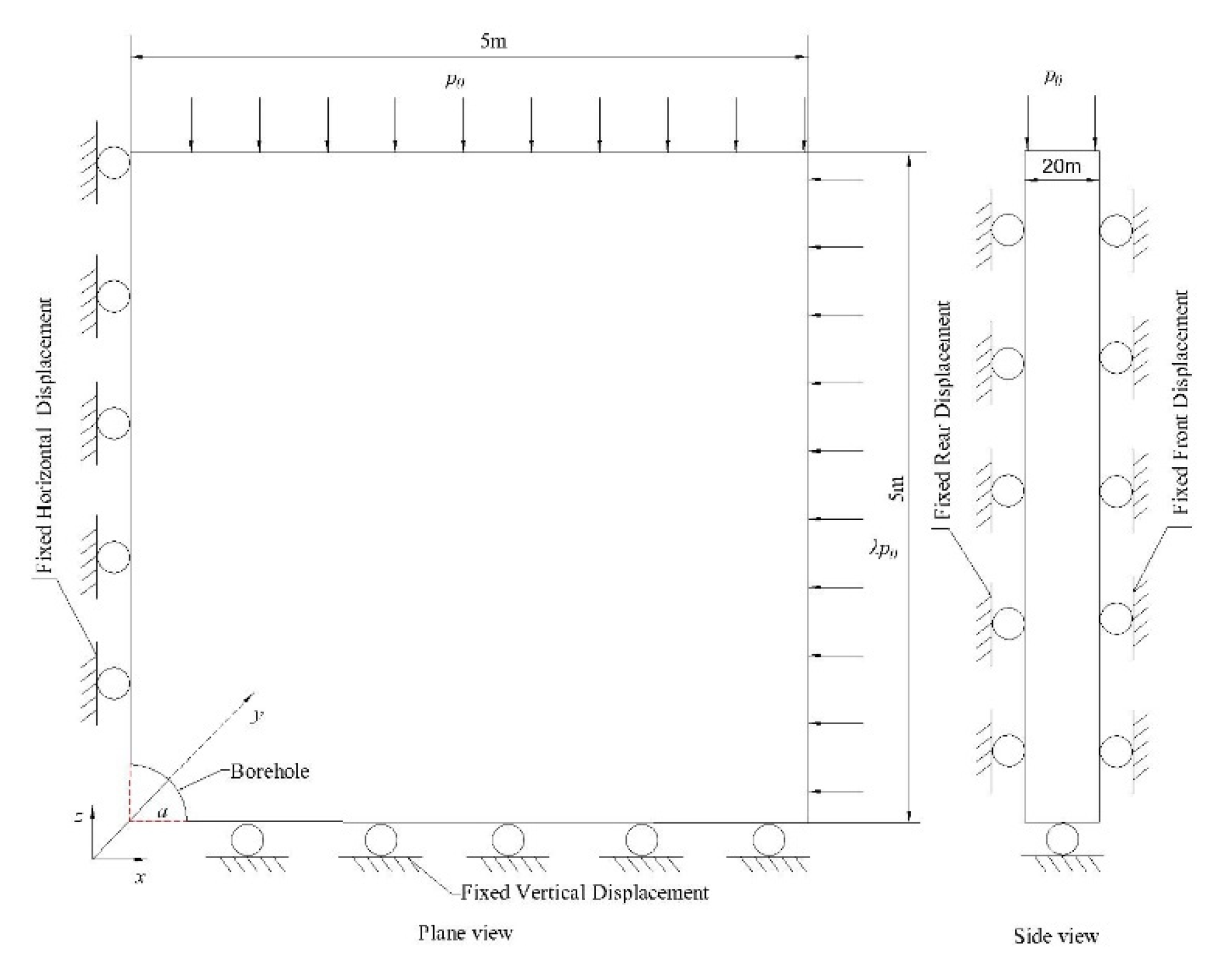
4.1. Numerical Model Establishment

The FLAC3D numerical simulation software was selected to study the effect of the borehole diameter on the pressure relief effect. Since the borehole model is axisymmetric, in order to simplify the calculation, a 1/4 model is used. Under the same other conditions, the borehole diameters were taken as 120 mm, 150 mm, 180 mm, and 200 mm, respectively. The size of the model is 5 m × 5 m × 20 m. The vertical loads and horizontal are applied to the upper and right sides, respectively, and the y displacement constraints are applied to the front and rear sides, the x displacement constraints are applied to the left sides, and the z displacement constraints are applied to the lower sides. The holes of different diameters are drilled in the middle. The schematic diagram of the force and constraints on the boundary of the model is shown in Figure 7. The Mohr–Coulomb yield criterion was used during the simulation. The specific model parameters are shown in Table 2.

4.2. Stress Distribution around Borehole

Under the condition of different borehole diameters, the stress distribution around the borehole is shown in Figure 8.
Drilling can act to fracture and soften the coal. When pressure relief drilling is carried out in the coal body, the coal body around the borehole will be fractured under the action of stress, and the fractured coal body will lose its bearing capacity, resulting in a stress reduction zone. The high-stress area in the coal body will be transferred to the deep part of the coal body, thereby reducing the damage to the surrounding rock on the roadway surface [25]. From the analysis of Figure 8, it can be seen that as the diameter of the borehole increases, the pressure relief range is also increasing. When the hole diameter is 120 mm and 200 mm, the pressure relief range is 168 mm and 288 mm, an increase of 71%. In the vertical direction, the vertical stress of the borehole first decreases and then restores to the original rock stress area, and in the horizontal direction, it first increases and then restores to the original rock stress area.

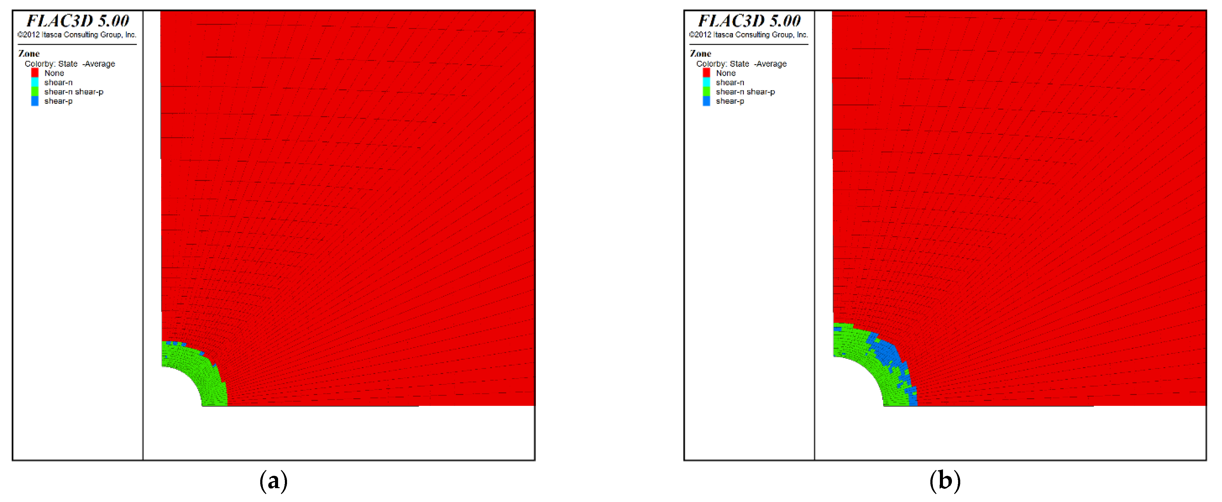
4.3. Distribution of Plastic Zone around the Borehole

Under the condition of different borehole diameters, the plastic zone around the borehole is shown in Figure 9.
When pressure relief drilling is performed in the coal body, the coal body around the borehole will rupture under the action of stress, resulting in a certain plastic region. The larger the plastic zone, the better the drilling pressure relief effect [25]. It can be seen from the analysis in Figure 9 that with the continuous increase in the borehole diameter, the area where the shear failure occurs becomes larger and larger. Larger bore diameters create more plastic failure zones inside the media, allowing for full impact pressure loads. The literature [26] analyzed the pressure relief effect when the borehole diameter was 60 mm, 80 mm, 100 mm, 120 mm, and 140 mm, and also pointed out that with the increase in the borehole diameter, the pressure relief effect is better.

4.4. Pressure Relief Effect of Subsection Reaming

The diameter of the borehole is selected from 100 mm to be drilled at a depth of 3 m, and then expanded to 200 mm and drilled at a depth of 20 m. The distribution of the stress and plastic zone around the borehole is shown in Figure 10.
From the analysis in Figure 10, it can be seen that the pressure relief range under the condition of segmental reaming is 404 mm, and the plastic zone range is 353 mm, which are both larger than the values when the diameter of the simple drilling is 200 mm. The pressure relief effect of segmental reaming is better than that of the single hole diameter, when it is 100 mm~200 mm.

5. Engineering Application

5.1. Monitoring Scheme

The pressure relief position of the variable diameter drilling is located in the mining roadway of the 74104 working face, which is 355 m away from the working face. On the mine site, a CMS1-6200 segmented drilling rig was used to construct the pressure relief hole. The construction pressure-relief hole is located in the middle of the coal wall. The hole diameter of the drilling hole is 120 mm first, and the hole is reamed after drilling for 3 m. When the diameter of the drill bit is expanded to 200 mm, the hole is drilled to 20 m. The pressure relief drilling spacing is 1 m and the length is 800 m. Meanwhile, a 42 mm check hole is implemented between the two pressure relief holes, and the drilling depth is 10 m to monitor the amount of pulverized coal in the hole and the phenomenon of stuck drilling.

5.2. Monitoring Result

The drilling cuttings method [27,28] has become an important means of predicting coal-mine rock burst. According to the 74,104 working face drilling pulverized-coal quantity-monitoring plan, the objectives are collecting the weight of the drilled pulverized coal, and obtaining the pulverized coal quantity of the drilled holes with different depths, as shown in Figure 11.
As the drill pipe drills the coal and rock mass, the drilling depth increases and the mining stress also gradually increases. The increase in the mining stress leads to the increase in the deformation of the coal body, and the larger hole diameter per unit volume causes the drill pipe to jump slightly, thereby leading to an increase in the amount of drill cuttings [25]. It can also be seen from Figure 11 that, with the increase in the drilling depth, the amount of pulverized coal gradually increases. When the drilling depth is 0 m−6 m, the amount of pulverized coal increases sharply. When the drilling depth is 6 m−10 m, the drilling pulverized coal quantity is stable. The literature [29] gives the critical value of the amount of pulverized coal in drilling, and when the maximum amount of pulverized drilling is less than 3 kg/m, there is no risk of impact. It can be seen that the amount of pulverized coal in all of the drilled holes is less than 3 kg/m, indicating that the effect of reducing the pressure relief is obvious. In addition, there are no dynamic phenomena, such as sticking, during the construction of the check hole.

6. Conclusions

(1)
A pressure relief mechanic model of segmented hole reaming was built. The boundary line equation for the plastic failure of the surrounding rock of the borehole can be obtained. When the drill hole is increased from 120 mm to 200 mm, the pressure relief range is increased by 57.1%. When the horizontal in situ stress coefficient increases from 0.8 to 1.2, the pressure relief range decreases by 12.4%;
(2)
The stress distribution of staged reaming and pressure relief drilling was also obtained. In the vertical direction, the vertical stress of the borehole first decreases and then restores to the original rock stress area, and in the horizontal direction, it first increases and then restores to the original rock stress area;
(3)
On the mine site, a CMS1-6200 segmented drilling rig was used to construct the pressure relief hole. The weight of the drilled pulverized coal was monitored at different depths. The result showed that the amount of pulverized coal in all of the drilled holes is less than 3 kg/m, indicating that the effect of reducing the pressure relief is obvious.

Author Contributions

Conceptualization, L.Z. and G.H.; methodology, P.H.; software, Y.C.; validation, S.L., B.L. and G.H.; formal analysis, P.H.; investigation, L.Z.; resources, L.Z.; data curation, G.H. and S.L.; writing—original draft preparation, P.H.; writing—review and editing, P.H.; visualization, Y.C.; supervision, B.L.; project administration, L.Z.; funding acquisition, P.H. All authors have read and agreed to the published version of the manuscript.

Funding

This research was funded by National Natural Science Foundation of China (Project No. 51608081).

Institutional Review Board Statement

Not applicable.

Informed Consent Statement

Not applicable.

Data Availability Statement

The data presented in this study are available on request from the corresponding author.

Conflicts of Interest

The authors declare no conflict of interest.

References

  1. Xie, H.; Gao, F.; Ju, Y. Research and Development of Rock Mechanics in Deep Ground Engineering. Chin. J. Rock Mech. Eng. 2015, 34, 2161–2178. [Google Scholar]
  2. He, H.; Dou, L.; Fan, J.; Du, T.; Sun, X. Deep-hole directional fracturing of thick hard roof for rockburst prevention. Tunn. Undergr. Space Technol. 2012, 32, 34–43. [Google Scholar] [CrossRef]
  3. Dou, L.-M.; Mu, Z.; Li, Z.; Cao, A.; Gong, S. Research progress of monitoring, forecasting, and prevention of rockburst in underground coal mining in China. Int. J. Coal Sci. Technol. 2014, 1, 278–288. [Google Scholar] [CrossRef] [Green Version]
  4. Liu, X.; Xu, G.; Zhang, C.; Kong, B.; Qian, J.; Zhu, D.; Wei, M. Time Effect of Water Injection on the Mechanical Properties of Coal and Its Application in Rockburst Prevention in Mining. Energies 2017, 10, 1783. [Google Scholar] [CrossRef] [Green Version]
  5. Gu, S.; Xiao, Z.; Huang, R.; Tan, Y.; Jiang, B.; Li, W. Rock Burst Danger Warning and Large Diameter Drilling Pressure–Relief Technology in Fully Mechanized Caving Island Coal Face; Atlantis Press: Paris, France, 2014. [Google Scholar]
  6. Wen, Y.; Zhang, G.; Zhang, Z. Numerical Experiments of Drilling Pressure Relief Preventing Roadway Rock Burst. Appl. Mech. Mater. 2013, 353–356, 1583–1587. [Google Scholar] [CrossRef]
  7. Zhang, S.; Li, J.; Ma, J. Roadway supporting technology applied to three soft coal seam at Yanlong mining area in China. Therm. Sci. 2019, 23, 124. [Google Scholar] [CrossRef] [Green Version]
  8. Jia, C.; Jiang, Y.; Zhang, X.; Wang, D.; Luan, H.; Wang, C. Laboratory and numerical experiments on pressure relief mechanism of large-diameter boreholes. Chin. J. Geotech. Eng. 2017, 39, 1115–1122. [Google Scholar]
  9. Wang, Q.; Pan, R.; Bei, J.; Li, S.; He, M.; Sun, H.; Wang, L.; Qin, Q.; Yu, H.; Luan, Y. Study on failure mechanism of roadway with soft rock in deep coal mine and confined concrete support system. Eng. Fail. Anal. 2017, 81, 155–177. [Google Scholar] [CrossRef]
  10. Cui, Q.; Meng, X.; Yang, S. Experimental investigation of influence of embedment depth and expanding ratio upon ultimate uplift resistance of hole digging foundation in rock. Rock Soil Mech. 2016, 37, 195–202. [Google Scholar]
  11. Huang, P.; Zhang, J.; Spearing, A.J.S.; Chai, J.; Dong, C. Experimental study of the creep properties of coal considering initial damage. Int. J. Rock Mech. Min. Sci. 2021, 139, 104629. [Google Scholar] [CrossRef]
  12. Fu, J.; Haeri, H.; Vahab, S.; Kaveh, A.; Pooyan, E.; Mohammad, F.M.; Guo, M. Extended finite element method simulation and experimental test on failure behavior of defects under uniaxial compression. Mech. Adv. Mater. Struct. 2021, 28, 2487–2502. [Google Scholar] [CrossRef]
  13. Haeri, H.; Sarfarazi, V.; Zhu, Z.; Marji, M.F. Simulating the influence of pore shape on the Brazilian tensile strength of concrete specimens using PFC2D. Comput. Concr. 2018, 22, 469–479. [Google Scholar]
  14. Vahab, S.; Shahin, F.; Kaveh, A.; Reza, B.; Wang, X. Failure Behavior of Room and Pillar with Different Room Configuration Under Uniaxial Loading Using Experimental Test and Numerical Simulation. Geotech. Geol. Eng. 2022, 40, 2881–2896. [Google Scholar]
  15. Zhang, W.; Ma, N.; Ma, J.; Li, C. Mechanism of Rock Burst Revealed by Numerical Simulation and Energy Calculation. Shock. Vib. 2020, 2020, 8862849. [Google Scholar] [CrossRef]
  16. Ning, J.; Liu, X.; Tan, Y. Mechanism of Rock-burst Prevention by Synergizing Pressure Relief and Reinforcement of Surrounding Rocks with Zonal Disintegration in Deep Coal Roadway. Disaster Adv. 2012, 5, 844–850. [Google Scholar]
  17. He, M.; Yang, B.; Zhang, Z.; Liu, X.; Li, N. Rock burst proneness prediction of rock materials based on rock digital drilling. Zhongnan Daxue Xuebao (Ziran Kexue Ban)/J. Cent. South Univ. (Sci. Technol.) 2021, 52, 2736–2747. [Google Scholar]
  18. Zhang, M.; Jiang, F. Rock burst criteria and control based on an abutment: Tress-transfer model in deep coal roadways. Energy Sci. Eng. 2020, 8, 2966–2975. [Google Scholar] [CrossRef]
  19. He, J.; Dou, L.; Cao, A.; Gong, S.; Lv, J. Rock burst induced by roof breakage and its prevention. J. Cent. South Univ. 2012, 19, 1086–1091. [Google Scholar] [CrossRef]
  20. Fairhurst, C.E.; Hudson, J.A. Draft ISRM suggested method for the complete stress-strain curve for intact rock in uniaxial compression. Int. J. Rock Mech. Min. Sci. Geomech. Abstr. 1999, 36, 281–289. [Google Scholar]
  21. Deng, H.; Li, J.; Deng, C.; Wang, L.; Lu, T. Analysis of sampling in rock mechanics test and compressive strength prediction methods. Rock Soil Mech. 2011, 32, 3399–3403. [Google Scholar]
  22. Song, Z.; Wang, J.; Jiang, A.; Liu, X.; Zhang, X. Ultrasonic tests on schist with saturated fractures under uniaxial compression. Chin. J. Rock Mech. Eng. 2014, 33, 2377–2383. [Google Scholar]
  23. Xue, Z. Elastic Mechanics; Higher Education Press: Beijing, China, 1990. [Google Scholar]
  24. Zhang, Y.; Hao, F.; Liu, C.; Liu, W. Borehole relief range considering plastic softening and dilatancy of coal. J. Liaoning Tech. Univ. (Nat. Sci.) 2013, 32, 1599–1604. [Google Scholar]
  25. Yi, E.; Mu, Z.; Dou, L.; Ju, J.; Xie, L.; Xu, D. Study on Comparison and Analysis on Pressure Releasing Effect of Boreholes in Soft and Hard Seam. Coal Sci. Technol. 2011, 39, 1–5+85. [Google Scholar]
  26. Li, Y.; Liu, S.; Cao, A.; Huang, X.; Gu, Y. Numerical analysis and application of coal pressure relief effectwith drillings in roadway. Coal Eng. 2016, 48, 50–53. [Google Scholar]
  27. Gu, S.; Wang, C.; Jiang, B.; Tan, Y.; Li, N. Field test of rock burst danger based on drilling pulverized coal parameters. Disaster Adv. 2012, 5, 237–240. [Google Scholar]
  28. Hu, S.; Lu, A.; Li, M.; Duan, T.; Chang, X. Research on the Mechanism of Rock Burst Prediction by Drilling Cutting Method. ARC J. 2017, 3, 81–88. [Google Scholar]
  29. Zhao, Y.; Jing, Z. Study on Critical Drilling Powder Amount of Rock Burst; Mine Press: Cortlandt, NY, USA, 1989; Volume 2, pp. 87–91. [Google Scholar]
Figure 1. Roadway fracture detection [9].
Processes 10 01566 g001
Figure 2. Pressure relief mechanic model. (a) Schematic diagram of segmented variable diameter drilling; (b) Mechanic model of segmented variable diameter drilling.
Processes 10 01566 g002
Figure 3. Pressure relief range of boreholes with different diameters. (a) a = 120 mm; (b) a = 150 mm; (c) a = 180 mm; (d) a = 200 mm.
Processes 10 01566 g003
Figure 4. Range of borehole pressure relief under different horizontal in situ stress coefficients. (a) λ = 0.8; (b) λ = 0.9; (c) λ = 1.1; (d) λ = 1.2.
Processes 10 01566 g004
Figure 5. Range of borehole pressure relief under different cohesive forces. (a) c = 3.0 MPa; (b) c = 4.0 Mpa; (c) c = 5.0 Mpa; (d) c = 6.0 Mpa.
Processes 10 01566 g005
Figure 6. Range of borehole pressure relief under different internal friction angles. (a) φ = 20°; (b) φ = 25°; (c) φ = 30°; (d) φ = 35°.
Processes 10 01566 g006
Figure 7. Schematic diagram of model boundary.
Processes 10 01566 g007
Figure 8. Stress distribution of rock mass with different borehole diameters. (a) 120 mm; (b) 150 mm; (c) 180 mm; (d) 200 mm.
Processes 10 01566 g008aProcesses 10 01566 g008b
Figure 9. Distribution map of the plastic zone of rock mass with different borehole diameters. (a) 120 mm; (b) 150 mm; (c) 180 mm; (d) 200 mm.
Processes 10 01566 g009aProcesses 10 01566 g009b
Figure 10. Distribution of stress and plastic zone around the borehole. (a) Distribution of stress; (b) Distribution of s plastic zone.
Processes 10 01566 g010
Figure 11. Amount of pulverized coal drilled at different depths.
Processes 10 01566 g011
Table 1. Mechanical properties of the coal samples.
Size
(mm)
Sectional Area
(cm2)
Breaking Load
(kN)
UCS
(MPa)
Average Value
(MPa)
Size
(mm)
Breaking Load
(kN)
UTS
(MPa)
Average Value
(MPa)
52.92 × 52.67 × 103.0027.8729.3815.017.4Φ49.51 × 27.532.751.401.41
52.53 × 52.58 × 102.6327.6224.5917.6Φ49.48 × 27.155.271.69
52.66 × 52.84 × 102.7127.8229.4319.6Φ49.55 × 27.184.191.13
Table 2. Model parameters.
ParameterBulk Modulus/GPaShear Modulus/GpaCohesion /MpaFriction /°Expansion Angle/°Tensile Strength/Mpa
Value3.92.82.8123.726.81.41
Publisher’s Note: MDPI stays neutral with regard to jurisdictional claims in published maps and institutional affiliations.

