Review

Application of Pure and Modified Polyvinylidene Fluoride Materials for Wastewater Treatment Using UASB Reactor Technologies: A Review

by
Mmontshi Lebohang Sikosana
1,*,
Keneiloe Khoabane Sikhwivhilu
2,
Richard Moutloali
3 and
Daniel Madyira
1
1
Department of Mechanical Engineering Science, University of Johannesburg, Johannesburg 2006, South Africa
2
Advanced Materials Division DSI/Mintek Nanotechnology Innovation Centre, Johannesburg 2194, South Africa
3
Institute for Nanotechnology and Water Sustainability, University of South Africa, Johannesburg 1709, South Africa
*
Author to whom correspondence should be addressed.
Processes 2024, 12(4), 734; https://doi.org/10.3390/pr12040734
Submission received: 19 February 2024 / Revised: 20 March 2024 / Accepted: 26 March 2024 / Published: 4 April 2024

Abstract

:
Wastewater treatment is now required because of the problems caused by water constraints. Wastewater is anaerobically digested to produce biogas, which can be used as a source of energy for things like lighting and heating. The upflow anaerobic sludge blanket (UASB) reactor has been recognized as an important wastewater treatment technology among anaerobic treatment methods. Although their treated effluent typically does not meet most discharge criteria, UASB reactors are generally stated to have a chemical oxygen demand (COD) reduction ranging from 60 to 90% for most types of wastewater. In comparison to traditional anaerobic procedures, anaerobic municipal wastewater treatment using membranes can produce higher effluent quality in terms of COD, suspended solids (SSs) and pathogen counts, as well as a steady treatment performance to fulfill strict discharge regulations. The objective of this review was to perform a literature review on parameters to consider when selecting a membrane to include in a UASB reactor. Membranes that are available in the market were compared in terms of both physical and chemical properties. Polyvinylidene fluoride (PVDF) membranes were found be superior to the others, and their modification also reduced the fouling propensity. When comparing modified PVDF (PVDF/PVDF-g-PEGMA) to pristine PVDF (116 L·m−2 h−1), a higher pure water flux (5170 L·m−2 h−1) was noted. The main drawback of such modifications could significantly increase the final membrane production costs. Research is still lacking when it comes to research on comparing the membranes and PVDF and UASB reactor technology interaction, including effects of its modification as discussed (stability, longevity of improved flux, etc.

1. Introduction

Owing to urbanization and industrialization, there is a greater need to reuse treated wastewater because of water shortages [1]. Upflow anaerobic sludge bed (UASB) reactors are a low-cost wastewater treatment technique that is widely employed, particularly in many tropical nations [2]. These systems have a number of benefits, including cheap operating costs, minimal sludge production, great efficiency in removing pollutants, and the ability to create methane for use as biofuel [3]. Many limitations exist with the UASB process, including its sensitivity to influent solids (which are removed ineffectively and prevent the formation of the granular bed), its inability to produce discharge-quality effluent (100 mg COD/L) in some countries, its inability to operate at lower temperatures, its inability to reactively remove nitrogen or phosphorus, and its difficulty in controlling the pH for high-strength wastewaters [4]. By effectively retaining biomass inside the reactor, the inclusion of membranes in UASB (AnMBRs) can create ideal conditions for the breakdown of organic matter without allowing suspended solids (SSs) to spill over [5]. In comparison to traditional anaerobic procedures, anaerobic municipal wastewater treatment using membranes can produce higher effluent quality in terms of COD, SSs, and pathogen counts, as well as steady treatment performance to fulfill strict discharge regulations [6]. The majority of wastewater treatment membranes are made from either polymeric or inorganic materials, with organic materials being more often used in the marketplace [7]. Among several polymeric membranes available for purchase are polysulfone, polyether sulfone, polyacrylonitrile, polyamide, polyimide, polyvinylidene fluoride, and polytetrafluoroethylene [8]. The most popular membrane material is polyvinylidene (PVDF), which has garnered significant interest from the scientific and industrial worlds [7,8,9].
This review’s goal was to conduct a survey of the literature on factors to take into account when choosing a membrane for a UASB reactor. Selected membranes that are available in the market were compared in terms of reported tests on both physical and chemical properties. An investigation was performed on the application of the superior membrane (PVDF) in a UASB reactor for anaerobic municipal wastewater treatment (AnPVDF/UASBR or AnMBR). AnMBR’s performances were measured in terms of the chemical oxygen demand (COD) removal and methane yield. This was then followed by investigating the modification of PVDF to reduce its fouling propensity.

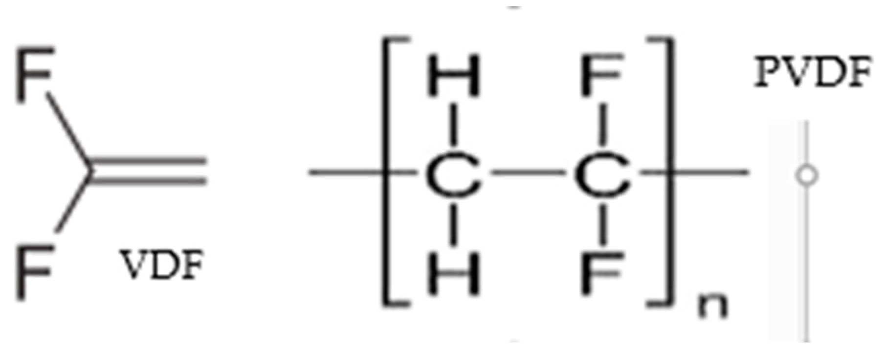
2. Polymer Physical and Chemical Tests

Figure 1 illustrates that only polytetrafluoroethylene (PTFE) breaks down at a temperature higher than PVDF among the chosen polymers. PVDF undergoes a mass loss of up to 60% at 430–459 °C under these circumstances, after which it stabilizes [10].
The research on the reactivity of peroxides from PVDF compared to those generated from polyethylene (PE) and polyvinyl chloride (PVC) after ozonization claims that PVDF radicals are more reactive than those from the other two membranes based on the dissociation rate constant (kd) and activation energy (Ea) [11]. It has been observed that PVDF has somewhat changed in color during the 20-year Florida exposure test, which is intended to evaluate a material’s ability to weather [12]. In a different study, PVDF was found to have increased gross retention by 15% over the course of four years in Florida [13]. In another instance, 20,000 h of PVDF exposure in a Weather-Ometer™ showed a marginal impact on its gross retention [14]. The majority of the other polymers are said to break down after 20,000 h of exposure in the Weather-Ometer [12]. A PVDF coating was found to be able to tolerate 3000 h of humidity exposure and salt spray in another test [15]. The prominence of PVDF in comparison to other polymeric materials may have resulted from these discoveries. Benzinger et al. [16] assessed a commercial Kynar PVDF ultrafiltration membrane at a high temperature in a thermal stability test. The scientists state that after seven months of continuous operation at 85.6 °C, there is no sign of heat damage. The comparison of three more membranes to PVDF in terms of the Florida tests, the Weather-Ometer, and gross retention is shown in Table 1.
PVDF exhibits exceptional features when compared to other polymers, including low weight (low density), excellent UV resistance, chemical and dimensional stabilities, ease of processing (melt-processable), mechanical strength, and retention of mechanical qualities [17]. PVDF is a potential option for wastewater treatment because of its resistance to strong halogenated compounds, acids, peroxides, aromatics, ozone, and other oxidants. Because of its increased toughness and ductility, the membrane itself requires less maintenance because it breaks and cracks less frequently during air-scouring and turbulent water flow operations [18]. PVDF is further discussed as the membrane of choice for the anaerobic treatment of municipal wastewater. The vinylidene fluoride (VDF) monomer (Figure 2), an odorless, colorless, combustible, and environmentally benign gas, is polymerized to create PVDF.
VDF has a boiling point of −82 °C, a freezing point of −144 °C, and a solubility of 6.4 cm3/100 g in water at 25 °C [19]. Under radical initiation methods, VDF is readily homopolymerized and copolymerized [20,21]. VDF can be added to expanding macroradicals via either conventional -CH2CF2–CH2CF2- (head-to-tail, H–T) or inverse -CH2CF2–CF2CH2- (head-to-head, H–H) and -CF2CH2–CH2CF2- (tail-to-tail, T–T) additions because of the asymmetry of the VDF monomer and because it is comparable to the hydrogen size of the fluorine atom [22]. PVDF is more common because PTFE materials are substantially more expensive than their PVDF counterparts because of their requirements for a costly thermal preparation technique [23]. Moreover, PTFE membranes have a low mechanical strength, an extremely low water permeability, and a superhydrophobic characteristic [24]. PVDF is made up of semicrystalline repeating units of -(CH2CF2)n-, as seen in Figure 2 [25].
Figure 2. VDF and PVDF’s structural formulae [20,21].
Processes 12 00734 g002

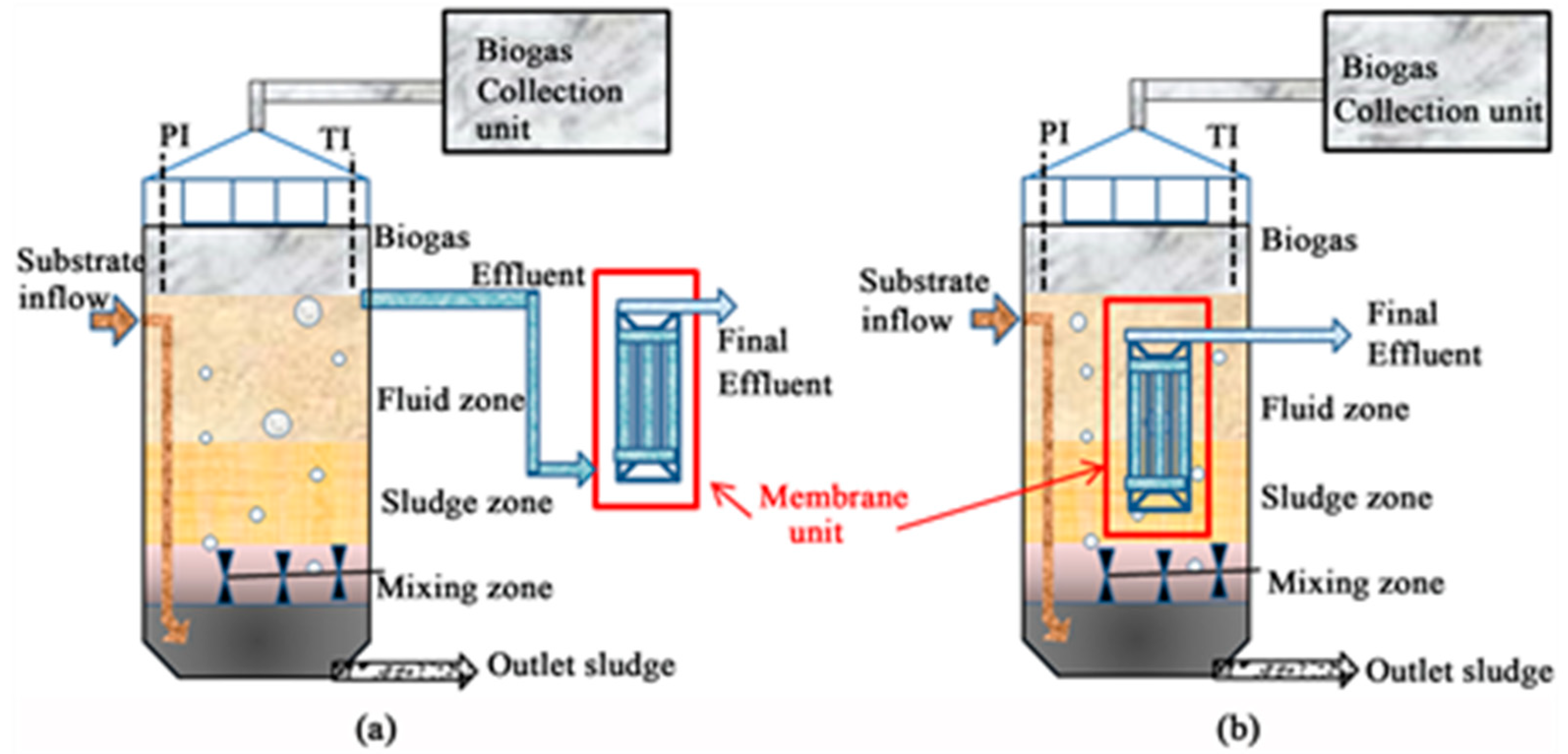
3. Typical AnPVDF/UASB Reactor Systems

Upflow anaerobic sludge beds (UASBs), hybrid UASBs, anaerobic filters, expanded granular sludge beds, and internal circulation reactors, among other commonly used anaerobic technologies, can achieve high organic-matter-removal efficiencies exceeding 90% [26]. Table 2 summarizes the advantages and disadvantages of UASB reactors [27].
By effectively retaining biomass inside the reactor, anaerobic membrane bioreactors (AnMBRs, in this case, BR denotes UASB, and M stands for membrane) can create ideal conditions for the breakdown of organic matter without allowing suspended solids (SSs) to spill over [5]. In comparison to traditional anaerobic procedures, anaerobic municipal wastewater treatment using membranes can produce higher effluent quality in terms of COD, SSs, and pathogen counts, as well as steady treatment performance to fulfill strict discharge regulations [28,29]. According to research, in many water-scarce places, AnMBR systems offer a way for treated wastewater to be used for non-potable agricultural applications [28]. The utilization of treated wastewater in agriculture typically necessitates the thorough elimination of pathogens and the provision of macronutrients [5]. Because pathogens can be retained by the membrane unit permeates of AnMBRs and macronutrients, like ammonium and orthophosphates, are not eliminated by anaerobic bioprocesses, AnMBRs are undoubtedly of interest for agricultural usage [29]. Applications of this technology are restricted by significant barriers to its utilization, including membrane fouling, poor flux, and high capital and operating expenses [30,31].
Two configurations of anaerobic membrane bioreactors (AnMBRs) are used: the submerged or immersed (right) configuration and the external, recirculated, or side-stream (left) configuration (Figure 3). In a side-stream AnMBR (Figure 3a), the permeate travels through the membrane under pressure, in contrast to a submerged AnMBR (Figure 3b), where the wastewater is removed either by suction or the head static pressure on the retentate side [32].
According to reports, oxidation occurs in natural settings to facilitate the microbial breakdown of organic material into inorganic compounds, with protons and sulfur or carbon atoms serving as the only electron sinks [33]. As shown in Figure 4, methane is the byproduct of the digestion of biodegradable organic species in an inert environment.
Figure 4 illustrates how a wide range of complex organic compounds can be converted to a variety of products by hydrolytic and fermentative microbes. In this illustration, organic acids and neutral substances bigger than methanol are converted to hydrogen and acetate by acetogenic bacteria. Methane is produced by methanogenic bacteria from acetate, hydrogen, and carbon dioxide. Removing acetate stops the solution from becoming acidic, whereas removing hydrogen causes the electrons to flow in a way that creates more oxidized intermediates. This phenomenon increases the other bacteria’s metabolic processes’ thermodynamic efficiency [33,34].
According to the following reactions (reactions 1 and 2), it is reported that 30% of the total methane produced in an anaerobic digestion comes from hydrogen and 70% comes from acetate [35]:
CH3COOH →CH4 + CO2
2H2 + CO2→CH4 + CO2
Because the creation of acetate is the rate-limiting stage in the production of methane, it is imperative that this step be satisfied by operating under favorable conditions. Methanogenesis is said to be preferred for the best methane production in the pH range from 6 to 8 [33]. It appears from earlier studies that pH levels can have a substantial impact on sludge digestion [33,36]. Wu et al.’s investigation looked into the mechanism leading to the synthesis and generation of volatile fatty acids (VFAs) [37]. The analysis of the bacterial community in a sewage sludge at various pH levels was another aspect of the experiment. The concentration of soluble protein was found to be 67.88% greater at pH 11.0 than it was at pH 3.0 by the authors. The overall VFA yield was 10.7 times higher at pH 9.0 than it was at pH 3.0. In terms of how pH affects the bacterial population, there were fewer germs in an acidic or an alkaline environment than in a neutral one. Another study looked at the impact of a pH range of 3.0–11 on primary sludge anaerobic digestion at room temperature [38]. It was shown that under alkaline conditions, the concentrations of the soluble chemical oxygen demand, soluble protein, carbohydrates, and short-chain fatty acids were much higher than those at other pH values. The digestion system’s short-chain fatty acid composition increased during the course of five days, going from 968 to 3511 mg COD/L as the pH increased from 3.0 to 10.0, respectively. This leads to the conclusion that the process by which biomass biodegrades is influenced by the pH. A helpful relationship to estimate the power that the UASB reactor system may generate per unit of methane produced is shown in Table 3. Table 3 gives an overview of the energy required and the amount of methane produced per volume from wastewater treated by UASB reactors.
The energy demand and resulting power that must be supplied are represented by the values in this table, which are used in the design of the wastewater treatment facility. According to the data in Table 3, the net energy produced is 2.6 kWh/m3 CH4. A summary of the methane output from several wastewater treatment facilities using PVDF/UASB reactor systems is shown in Table 4. The following text provides a quick summary of the parameters’ effects that are reported in Table 4 and Table 5.
Different modules viz. hollow, flat, and tubular membranes are shown in Figure 5. Table 4 and Table 5 demonstrate how hollow fiber (HF) PVDF membranes appear to be used extensively in UASB reactor systems. The low cost and high packing density of HF membrane modules are advantages [44]. According to reports, FS (flat sheet) membranes typically cost 20–25% more than HF membranes [44]. Compared to HF arrangements, FSs have an additional advantage in terms of fouling propensity and maintenance [41]. Table 4 shows a minor variance in methane outputs under the same wastewater treatment conditions but with various AnMBR configurations (external vs. submerged).
Figure 5. Hollow, flat, and tubular membranes (from left to right) [45].
Processes 12 00734 g005
Table 5. The efficacies of some wastewater anaerobic PVDF/UASB reactor systems.
ConfigurationMembrane CharacterScale
(L)
Influent COD
(mg/L)
Operation ConditionsCOD Removal
(%)
Ref.
ExtHF
0.22 µm
4330–370T: 20 °C
pH: n/a
HRT: 12 h
91.9[9]
SubHF
0.22 µm
4330–370T: 20 °C
pH: n/a
HRT: 12 h
91.3[9]
SubFS
70,000 Da
302600T: 20 and 55 °C
pH: 7
HRT: n/a
99.99[46]
SubHF
0.40 µm
942200T: 37 °C
pH: n/a
HRT: 47 d
>98[47]
SubFS
0.10 µm
1100–800T: 15 °C
pH: n/a
HRT: 0.32 d
86.2[48]
SubFS
140,000 Da
80342–527T: 30 °C
pH: 7
HRT: 10 h
90.0[41]
ExtFS
0.40 µm
80 11,224–12,898T: n/a
pH: 7.1
HRT: 40 h
90.0[42]
Notes: Ext: external; Sub: submerged; HF: hollow fiber; FS: flat sheet; HRT: hydraulic retention time.
Because there are numerous factors to take into account, including the system’s hydrodynamics and thermodynamics, it is difficult to explain this discovery. There is an observed difference in methane production that is evident for the PVDF membranes with different pore sizes and reactor configurations. In comparison to its larger-pore membrane counterpart [9] (~45%), a considerable amount of methane (~67%) was produced [41] for the smaller-pore membrane. This could be because organic material has a high pore resistance to passing through the membrane, which prevents more methanogenesis from occurring on the membrane. The properties of the feed wastewater have an impact on methane production. The reference tables, which include Table 4 and Table 5, make it clear that methane generation will increase with the influent’s COD content. Because microorganisms in a biological medium are more active at higher temperatures, the COD removal efficiency increases (Table 4). The solubilities of organic and inorganic substances, the solubility of biogas, and the settling properties of biological solids are all influenced by the temperature. Table 4 and Table 5 do not clearly show the impact of the hydraulic retention time (HRT) because of other factors, such the notable variations in the influent’s COD content. At a fixed temperature of 35 °C, the COD concentrations in the reactor and permeate increased marginally as the HRT decreased [49].

4. Brief Comparison of a PVDF/UASB System and a Conventional UASB Reactor

AnMBRs were developed as a result of the use of membranes in the wastewater treatment industry. Table 4 and Table 5 show that the AnMBR system has achieved outstanding results by eliminating several procedures that follow the standard USAB reactor. The anaerobic digestion of household wastewater was studied using a comparison between a regular UASB and an AnMBR (Table 6) [47].
Researchers have looked into how the microbial community was affected by the reactor’s arrangement. AnMBR was predicted to retain all the biomass in these reactors, although some bacteria are washed away in conventional UASBs. The membrane reportedly helped to remove dissolved methane from the liquid phase according to the authors. Totals of 8.9 and 16.3% methane for AnMBR and UASB, respectively, were found in the effluent. According to the authors, the aqueous body’s turbulent mixing occurred via the membrane biofilm. In other comparisons, the composition of CH4 was found to be 2–3 percentage points higher in the membrane module than in the UASB reactor, whereas the composition of the methane was found to be 2–3 percentage points lower in the AnMBR than in the UASB reactor’s effluent [49]. The authors ascribe the variation in the methane composition of the effluent to the 1.5–2 °C higher temperature in the AnMBR compared to the UASB reactor. Recirculation was also found to affect biogas generation in the same investigation, with 26.4 recirculated and 13.7% non-recirculated in the AnMBR. These outcomes demonstrate the membrane’s beneficial role in the total methane production (Table 6).

5. Modification of PVDF Membrane to Reduce Fouling during Wastewater Treatment

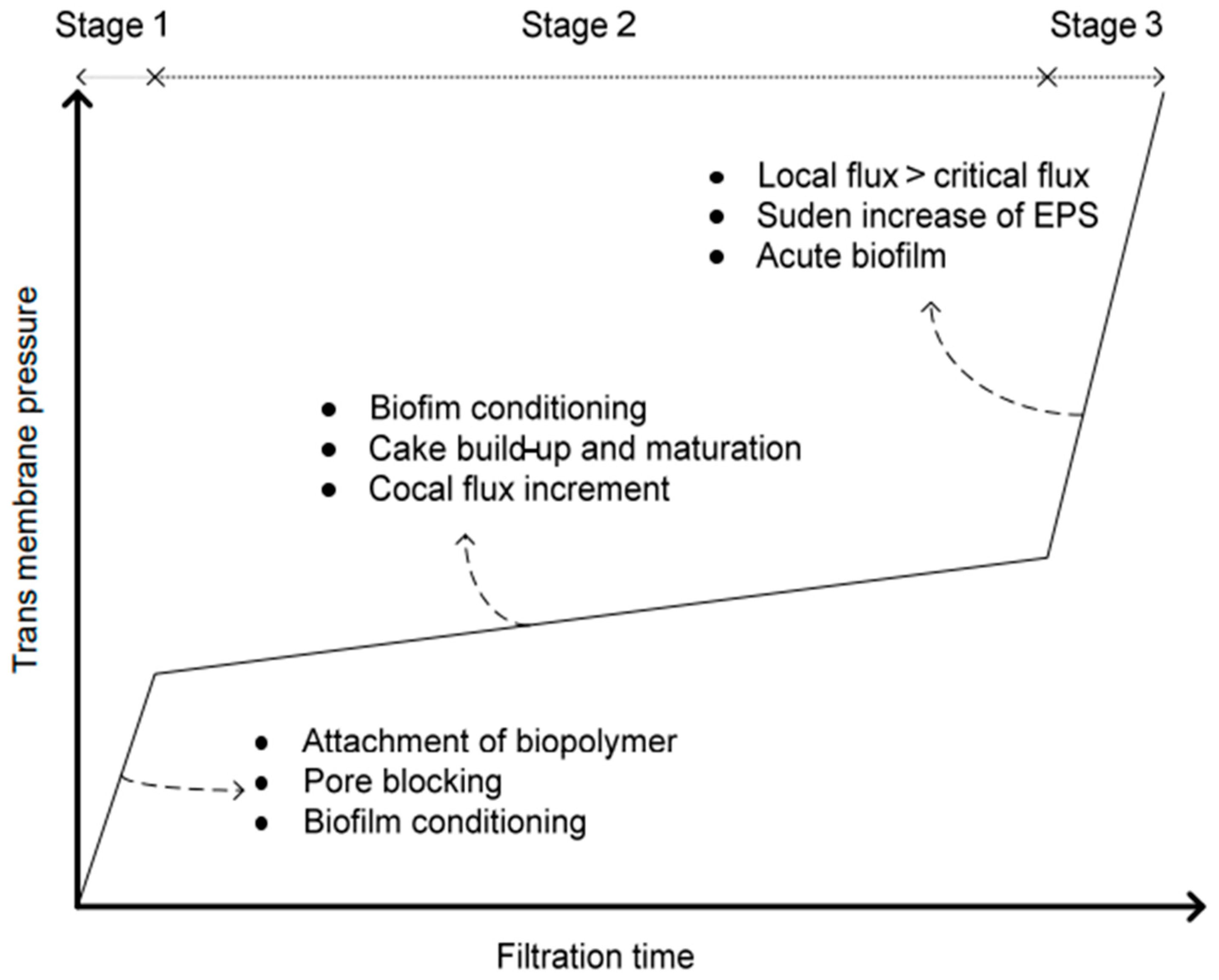
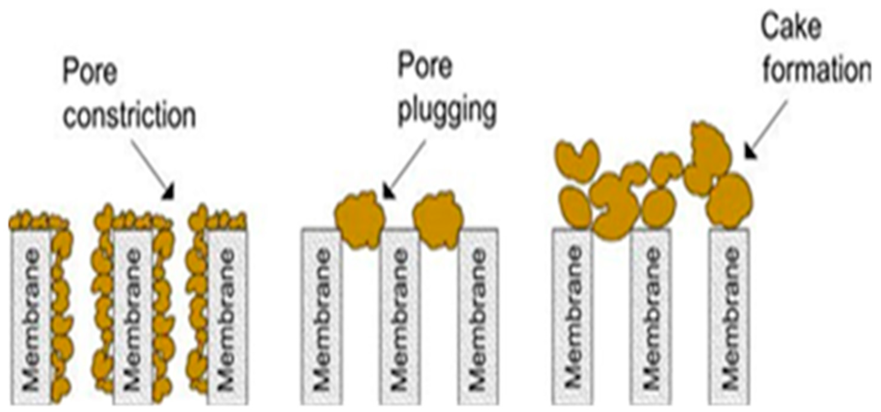
5.1. Fouling Process

The deposition of soluble and particulate contaminants into or onto pores of membranes is referred to as fouling. When using a constant pressure mode, fouling is identified by an observed drop in the flux and an increase in the TMP when running at a constant flux [50]. The majority of the time, MBRs are run in the continuous flux mode. Membrane fouling can be identified by monitoring TMP values during the filtration process [51]. The mechanism of TMP changes in three stages (Figure 6) [52]; the first stage represents pore blocking and adsorption on the surface, whereas the second stage is marked by an increase in the TMP. The TPM’s sharp increase in stage 3 indicates severe fouling [52].
Delaying the TMP leap and any associated expenses for membrane cleaning or replacing old membrane modules is essential to this style of operation [53]. Membrane fouling is categorized as either irreversible or reversible based on the results of a straightforward cleaning process, such as relaxing, air scouring, or backwashing, to recover the flux. When irreversible fouling occurs and the desired flow is not obtained, chemical membrane cleaning is used, as shown in Figure 7 [54].
Fouling is categorized as biological, organic, or inorganic fouling depending on chemical and biological properties of membrane foulants [55]. The deposition of foulants, such as bacteria, colloids, and solutes, on a membrane’s surface results in biofouling, or biological fouling, in AnMBRs and reduces their performance [53]. Biofouling is reported to contribute to about 45% of all the membrane fouling [56]. The term “inorganic fouling” describes the precipitation or deposition of a class of inorganic materials, such as cations and anions, like Mg2+, Fe3+, and Al3+ and SO42−, PO43−, and OH, respectively, on a membrane’s surface [57]. Organic fouling includes dissolved organic carbon, hydrophilic organics, humic compounds, and tiny-molecular-weight organic materials. Membrane fouling can be in the form of pore narrowing (constriction), pore clogging, or cake formation, as depicted in Figure 8 [58].
Pore constriction results from small particles adsorbing on the walls inside the pores, narrowing the size with the growth of the layer, which may end up blocking the membrane. Cake development depends on the constant deposition of foulants, whereas clogging is a result of particles with sizes larger than those of the membrane’s pores [58].

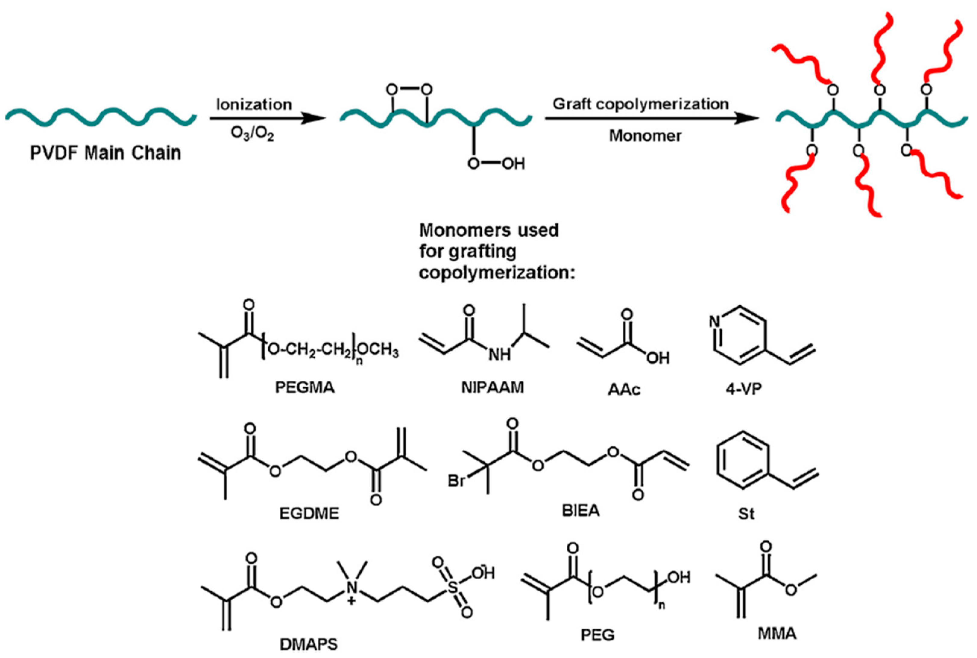
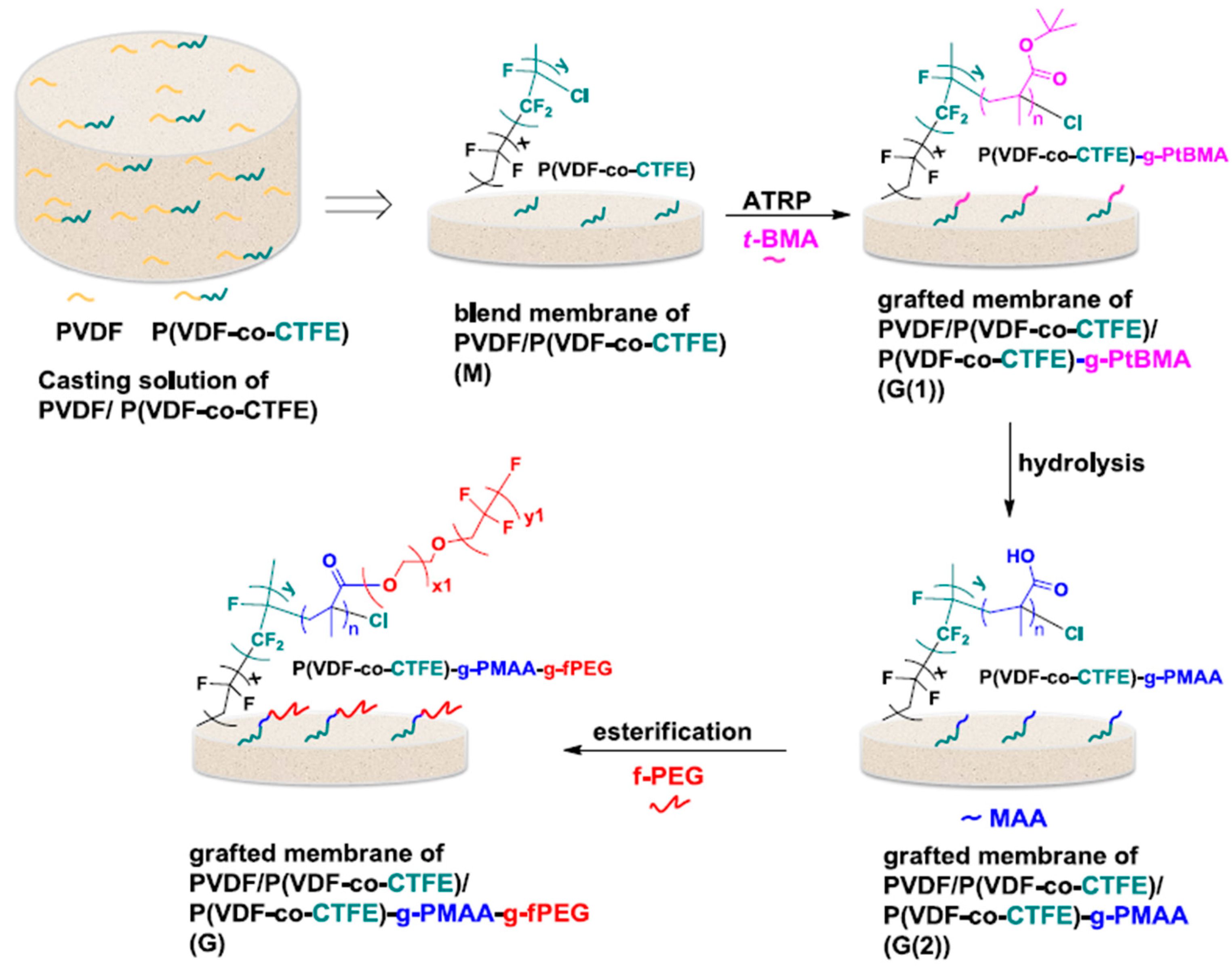
5.2. Modification of PVDF

Graft copolymers with stiff crystalline stems are anticipated to be a strong contender for the creation of well-structured porous assemblies (Scheme 1) [19].
The antifouling capabilities of poly(VDF-g-M), where ‘M’ stands for a hydrophilic monomer, were demonstrated to have improved [59]. This addition can be utilized in the production of membranes for alternative treatment methods in water and wastewater management. In order to prepare flawless and highly effective ultrafiltration membranes, it is crucial to graft hydrophilic acrylate polymers using the atom transfer radical polymerization (ATRP) procedure, as shown in Scheme 2 [60].
The perfluoroalkyl PEG surfactant was used to esterify the P(VDF-co-CTFE)-g-PMAAc membrane that was produced following the hydrolysis of poly(tert-butyl acrylate) (PtBA) grafts [61]. Additionally significant as potential antifouling membrane materials for various waste processes in the chemical, biological, and pharmaceutical industries are PVDF-g-PEGMA copolymers [62]. Earlier research has shown that PVDF-g-PEGMA can be added to PVDF-blended membranes to “PEGylate” their surface and improve their hydrophilicity and resistance to fouling. For example, PVDF membranes were produced by Hashim et al. by combining PVDF-g-PEGMA and unreacted PEGMA from the ATRP technique, which was utilized to synthesize graft copolymers with the PVDF homopolymer [63]. A few years later, the Crittenden and Chen groups succeeded in achieving at least one order of magnitude higher pure water flux (5170 L·m−2 h−1) for their own PVDF/PVDF-g-PEGMA blends despite the fact that the authors had emphasized the low number of steps required and the higher pure water flux in comparison with that of the pristine PVDF (116 L·m−2 h−1) [64]. By appropriately adjusting the PVDF/PVDF-g-PEGMA/solvent ratio in this instance, the authors observed a pillar-like structure free of defects. In a recent series of studies, the same group looked into the development mechanism of the previously stated pillar-like structures by varying the additive and solvent [65]. The researchers revealed that in order to create these unique “pillar-like” structures, 1-methyl-2-pyrrolidinone and PVDF-gPEGMA must coexist in the membrane-casting solutions. Meanwhile, the membranes described by the authors achieved a pure water reflux value of 2173 L·m−2 h−1. The authors of the same experiment came to the conclusion that more PEGMA segments can migrate to PVDF-g-PEGMA along the membrane’s surface if there is more leftover PEGMA in the casting solution. In order to improve the membrane’s flux performance for the same kind of mixtures, Crittenden and Chen’s groups were able to directly regulate the reaction time of the ATRP process, which allowed them to modify the membrane pore size [66]. The modified PVDF membranes with PVDF-g-PEGMA at different reaction times of 9 h, 19 h, and 29 h exhibited a high flux performance for pure water, which was 5445 L·m−2h−1, 1068 L·m−2h−1, and 1179 L·m−2h−1, respectively, at 0.07 MPa [66]. In that study, the membrane pore size was adjusted by controlling the reaction time of the PVDF-g-PEGMA to obtain a better membrane flux performance.

6. Concluding Remarks

It has been demonstrated that the pH level influences how much organic matter is broken down. According to the previously discussed data, a pH range of near neutral is the most appropriate, with recommended values falling between 6.3 and 7.8. It has been demonstrated that maintaining pH control within this range is achievable with the use of hydrogen carbonate as a buffer. The anaerobic process’s benefits usually become apparent when the influent concentration exceeds 250 mg COD/L. The ideal temperature falls between 35 and 38 degrees Celsius. The HRT affects how quickly things degrade, and it should not be less than two hours. The subsequent elimination of the COD and the formation of methane are influenced by additional factors, such as trace metals. The system’s final performance is mostly determined by the intended wastewater treatment output in terms of the water that is suitable for the intended use and the amount of methane that will be generated for that use (heat, power, chemicals, etc.). The higher dissolved methane recovery rate of the AnMBR compared to that of the UASB could not justify its cost, complexity, and potential downsides. The net energy generations for the AnMBR and the UASB were −0.2211 and 0.0407 kWh/m3 CH4, respectively. Therefore, it is essential to choose the reactor depending on the intended results for energy use and water quality.
PVDF has distinguished properties and exceptional performance under harsh conditions. PVDF can last at high temperatures and under volatile weather conditions, with excellent resistance to sunlight degradation and high solar transmittance rates. In addition, this chemically inert polymer is highly effective in resisting solvents, chemicals, corrosion, and water absorption. This polymer is meant to be applied where chemical resistance, mechanical strength, stain resistance, release properties, outdoor durability, thermal stability, low permeability, and adhesion are required.
This review makes it clear that little research has been conducted on how robustly different membranes compare to one another. Compared to UASB reactors without the membrane, the membrane has relatively little effect on the total amount of methane produced. Research on both the physical and chemical stabilities of modified PVDF membranes during wastewater treatment still need to be conducted. The effect of the membrane emphasizes the removal of pathogens, which was not a part of this review and will be dealt with in the future. A higher pure water flux (5170 L·m−2 h−1) was achieved for the modified PVDF (PVDF/PVDF-g-PEGMA) in comparison with the pristine PVDF (116 L·m−2 h−1). In addition to PVDF being highlighted as the preferred membrane for wastewater treatment, its modification is needed to reduce fouling. The main drawback of such modifications could significantly increase the final membrane production costs.

Author Contributions

M.L.S. conducted the literature search, review and wrote the first draft. K.K.S., R.M. and D.M. are supervisors for the PhD candidacy work that M.L.S. is responsible for reviewing the work (guiding the writing process towards submission readiness) and ensuring that funds are available as needed. All authors have read and agreed to the published version of the manuscript.

Funding

This research was funded by the University of Johannesburg, grant number [05-05-067090]. The research funded in part by the LIRA 2030 Africa Programme served as the basis for this review. In collaboration with the Network of African Science Academies, the International Science Council (ISC) acts as an implementing agent (NASAC). The Swedish International Development Cooperation Agency (SIDA) also provides support for this activity.

Data Availability Statement

Data are contained within the article.

Acknowledgments

The University of Johannesburg, Departments of Applied Chemistry, Chemical Engineering Sciences, and Mechanical Engineering Sciences provided support for which the authors are grateful. The money and authorization from the Department of Science and Innovation (DSI)/Mintek Nanotechnology Innovation Centre to present these findings are also appreciated by the authors.

Conflicts of Interest

No conflict of interest was known at the writing of this document.

References

  1. El Khateeb, M.; Hassan, G.K.; El Liethy, M.A.; El Khatib, K.M.; Abdel Shafy, H.I.; Hu, A.; Gad, M. Sustainable municipal wastewater treatment using an innovative integrated compact unit: Microbial communities, parasite removal, and techno economic analysis. Ann. Microbiol. 2023, 73, 35. [Google Scholar] [CrossRef]
  2. Arthur, P.M.; Konaté, Y.; Sawadogo, B.; Sagoe, G.; Dwumfour-Asare, B.; Ahmed, I.; Bayitse, R.; Ampomah-Benefo, K. Evaluating the Potential of Renewable Energy Sources in a Full-Scale Upflow Anaerobic Sludge Blanket Reactor Treating Municipal Wastewater in Ghana. Sustainability 2023, 15, 3743. [Google Scholar] [CrossRef]
  3. Vassalle, L.; Díez-Montero, R.; Machado, A.T.; Moreira, C.; Ferrer, I.; Mota, C.R.; Passos, F. Upflow anaerobic sludge blanket in microalgae-based sewage treatment: Codigestion for improving biogas production. Bioresour. Technol. 2020, 300, 122677. [Google Scholar] [CrossRef]
  4. Rattier, M.; Jimenez, J.A.; Miller, M.W.; Dhanasekar, A.; Willis, J.; Keller, J.; Batstone, D. Long-term comparison of pilot UASB and AnMBR systems treating domestic sewage at ambient temperatures. J. Environ. Chem. Eng. 2022, 10, 108489. [Google Scholar] [CrossRef]
  5. Ozgun, H.; Dereli, R.K.; Ersahin, M.E.; Kinaci, C.; Spanjers, N.; Van Lier, J.B. A review of anaerobic membrane bioreactors for municipal wastewater treatment: Integration options, limitations and expectations. Sep. Purif. Technol. 2013, 118, 89–104. [Google Scholar] [CrossRef]
  6. Ho, J.; Sung, S. Methanogenic activities in anaerobic membrane bioreactors (AnMBR) treating synthetic municipal wastewater. Bioresour. Technol. 2010, 101, 2191–2196. [Google Scholar] [CrossRef]
  7. Kang, G.; Cao, Y. Application and modification of poly(vinylidene fluoride) (PVDF) membranes—A review. J. Membr. Sci. 2014, 463, 145–165. [Google Scholar] [CrossRef]
  8. Judd, S.J. The status of industrial and municipal effluent treatment with membrane bioreactor technology. Chem. Eng. J. 2016, 305, 37–45. [Google Scholar] [CrossRef]
  9. Chen, C.; Guo, W.; Ngo, H.H.; Chang, S.W.; Nguyen, D.D.; Nguyen, P.D.; Bui, X.T.; Wu, Y. Impact of reactor configurations on the performance of a granular. Int. Biodeterior. Biodegrad. 2017, 121, 131–138. [Google Scholar] [CrossRef]
  10. Marshall, J.E.; Zhenova, A.; Roberts, S.; Petchey, T.; Zhu, P.; Dancer, C.E.J.; McElroy, C.R.; Kendrick, E.; Goodship, V. On the Solubility and Stability of Polyvinylidene Fluoride. Polymers 2021, 13, 1354. [Google Scholar] [CrossRef]
  11. Boutevin, B.; Pietrasanta, Y.; Robin, J.J. Synthese et application de copolymeres graffes a base de polyfluorrure de vinylidene-I. Euro Polym. 1991, 27, 815–820. [Google Scholar] [CrossRef]
  12. Wypych, W. Handbook of Material Weathering, 6th ed.; ChemTech Publishing: Toronto, ON, Canada, 2018. [Google Scholar]
  13. Scheirs, J.; Burks, S.; Locaspi, A. Developments in fluoropolymer coatings. Trends Polym. Sci. 1995, 3, 74–82. [Google Scholar]
  14. Bartoszek, E.J.; Perillon, J.L. Long-Life Coating with PVDF Polymers. Surf. Coat. J. 1995, 78, 371–376. [Google Scholar]
  15. Hopfstock, H. Paint removal composition and system. Paint. Ink Int. 1997, 10, 1–23. [Google Scholar]
  16. Benzinger, W.D.; Parekh, B.S.; Eichelberger, J.L. High temperature ultrafiltration with Kynar poly(vinylidene fluoride)membranes. Sep. Sci. Technol. 1980, 15, 1193–1204. [Google Scholar] [CrossRef]
  17. Zeus Technical Account. New Focus on PVDF; Zeus Industrial Products Inc.: Orangeburg, SC, USA, 2019. [Google Scholar]
  18. Hu, X.; An, A.K.J.; Chopra, S.S. Life Cycle Assessment of the Polyvinylidene Fluoride Polymer with Applications in Various Emerging Technologies. ACS Sustain. Chem. Eng. 2022, 10, 5708–5718. [Google Scholar] [CrossRef]
  19. Zapsas, G.; Patil, Y.; Gnanou, Y.; Ameduri, B.; Hadjichristidis, N. Poly(vinylidene fluoride)-based complex macromolecular architectures: From synthesis to properties and applications. Prog. Polym. Sci. 2020, 104, 101231. [Google Scholar] [CrossRef]
  20. Ameduri, B. From vinylidene fluoride (VDF) tothe applications of VDF-containing polymers and copolymers: Recent and future trends. Chem. Rev. 2009, 109, 6632–6686. [Google Scholar] [CrossRef]
  21. Guiot, J.; Ameduri, B.; Boutevin, B. Radical homopolymerization of vinylidene fluoride initiated by tert-butyl peroxypivalate. Investigation of the microstructure by 19F and 1H NMR spectroscopies and mechanisms. Macromolecules 2002, 35, 8694–8697. [Google Scholar] [CrossRef]
  22. Pladis, P.; Alexopoulos, A.H.; Kiparissides, C.J. Mathematical modeling and simulation of vinylidene fluoride emulsuin polymerization. Ind. Eng. Chem. 2014, 53, 7352–7364. [Google Scholar] [CrossRef]
  23. Liu, T.; Zhou, X.; Sun, Y.; Bai, R. Anticorrosion Performance of PVDF Membranes Modified by Blending PTFE Nanoemulsion and Prepared through Usual Non-Solvent-Induced Phase Inversion Method. Membranes 2021, 11, 420. [Google Scholar] [CrossRef]
  24. Park, G.C.; Kim, D. Porous PTFE reinforced SPEEK proton exchange membranes for enhanced mechanical, dimensional, and electrochemical stability. Polymer 2021, 218, 123506. [Google Scholar] [CrossRef]
  25. Saxena, P.; Shukla, P. A comparative analysis of the basic properties and applications of poly (vinylidene fuoride) (PVDF) and poly (methyl methacrylate) (PMMA). Polym. Bull. 2022, 79, 5635–5665. [Google Scholar] [CrossRef]
  26. Osman, R.M.; Hodaifa, G. An overview of anaerobic membrane bioreactors: Current developments, fouling problems, and future prospects. J. Environ. Chem. Eng. 2023, 11, 111482. [Google Scholar] [CrossRef]
  27. Daud, M.K.; Rizvi, H.; Akram, M.F.; Ali, S.; Rizwan, M.; Nafees, M.; Jin, Z.S. Review of Upflow Anaerobic Sludge Blanket Reactor Technology: Effect of Different Parameters and Developments for Domestic Wastewater Treatment. J. Chem. 2018, 2018, 1596319. [Google Scholar] [CrossRef]
  28. Martinez-Sosa, D.; Helmreich, B.; Netter, T.; Paris, S.; Bischof, F.; Horn, H. Pilot-scale anaerobic submerged membrane bioreactor (AnSMBR) treating municipal wastewater: The fouling phenomenon and long-term operation. Water Sci. Technol. 2011, 64, 1804–1811. [Google Scholar] [CrossRef]
  29. Ellouze, M.; Saddoud, A.; Dhouib, A.; Sayadi, S. Assessment of the impact of excessive chemical additions to municipal wastewaters and comparison of three technologies in the removal performance of pathogens and toxicity. Microbiol. Res. 2009, 164, 138–148. [Google Scholar] [CrossRef]
  30. Kocadagistan, E.; Topcu, N. Treatment investigation of the Erzurum City municipal wastewaters with anaerobic membrane bioreactors. Desalination 2007, 216, 367–376. [Google Scholar] [CrossRef]
  31. Zhang, X.; Wang, Z.; Wu, Z.; Lu, F.; Tong, J.; Zang, L. Formation of dynamic membrane in an anaerobic membrane bioreactor for municipal wastewater treatment. Chem. Eng. J. 2010, 165, 175–183. [Google Scholar] [CrossRef]
  32. Jain, M. Anaerobic Membrane Bioreactor as Highly Efficient and Reliable Technology for Wastewater Treatment—A Review. Adv. Chem. Eng. Sci. 2018, 8, 82–100. [Google Scholar] [CrossRef]
  33. Seghezzo, L. Anaerobic Treatment of Domestic Wastewater in Subtropical Regions; Wageningen University and Research: Wageningen, The Netherlands, 2004. [Google Scholar]
  34. Balch, W.E.; Fox, G.E.; Magrum, L.J.; Woese, C.R.; Wolfe, R.S. Methanogens: Reevaluation of a Unique Biological Group. Microb. Rev. 1979, 43, 260–296. [Google Scholar] [CrossRef]
  35. Gujer, W.; Zehnder, A.J. Conversion processes in anaerobic digestion. Water Sci. Technol. 1983, 15, 127–167. [Google Scholar] [CrossRef]
  36. Yu, H.; Wang, Z.; Wang, Q.; Wu, Z.; Ma, J. Disintegration and acidification of MBR sludge under alkaline conditions. Chem. Eng. J. 2013, 231, 206–213. [Google Scholar] [CrossRef]
  37. Wu, H.; Yang, D.; Zhou, Q.; Song, Z. The effect of pH on anaerobic fermentation of primary sludge at room temperature. J. Hazard. Mater. 2009, 172, 196–201. [Google Scholar] [CrossRef]
  38. Liu, H.; Wang, J.; Liu, X.; Fu, B.; Chen, J.; Yu, H. Acidogenic fermentation of proteinaceous sewage sludge: Effect of pH. Water Res. 2012, 46, 799–807. [Google Scholar] [CrossRef]
  39. TBW GmbH. Anaerobic Treatment of Municipal Wastewater in UASB-Reactors; Technical Information W6e, gtz; TBW GmbH: Frankfurt, Germany, 2001. [Google Scholar]
  40. Chen, R.; Nie, Y.; Kato, H.; Wu, J.; Utashiro, T.; Lu, J.; Yue, S.; Jiang, H.; Zhang, L.; Li, Y.Y. Methanogenic degradation of toilet-paper cellulose upon sewage. Bioresour. Technol. 2017, 228, 69–76. [Google Scholar] [CrossRef]
  41. Gouveia, J.; Plaza, G.; Garralon, G.; Fdz-Polanco, F.; Pena, M. Long-term operation of a pilot scale anaerobic membrane bioreactor. Bioresour. Technol. 2015, 185, 225–233. [Google Scholar] [CrossRef]
  42. Lin, H.; Chen, J.; Wang, F.; Ding, L.; Hong, H. Feasibility evaluation of submerged anaerobic membrane bioreactor for municipal secondary wastewater treatment. Desalination 2011, 280, 120–126. [Google Scholar] [CrossRef]
  43. Umaiyakunjaram, R.; Shanmugam, P. Study on submerged anaerobic membrane bioreactor (SAMBR) treating high suspended solids raw tannery wastewater for biogas production. Bioresour. Technol. 2016, 216, 785–792. [Google Scholar] [CrossRef]
  44. Le-Clech, P.; Chen, V.; Fane, T.A. Fouling in membrane bioreactors used in wastewater treatment. J. Membr. Sci. 2006, 284, 17–53. [Google Scholar] [CrossRef]
  45. Amin, S.K.; Abdallah, H.M.; Roushdy, M.H.; El-Sherbiny, C.A. An Overview of Production and Development of Ceramic Membranes. Int. J. Appl. Eng. Res. 2016, 11, 7708–7721. [Google Scholar]
  46. Lin, H.J.; Xie, K.; Mahendran, B.; Bagley, D.M.; Leung, K.T.; Liss, S.N.; Liao, B.Q. Sludge properties and their effects on membrane fouling in submerged anaerobic membrane bioreactors (SAnMBRs). Water Res. 2009, 43, 3827–3837. [Google Scholar] [CrossRef] [PubMed]
  47. Berkessa, Y.W.; Yan, B.; Li, T.; Tan, M.; She, Z.; Jegatheesan, V.; Jiang, H.; Zhang, Y. Novel anaerobic membrane bioreactor (AnMBR) design for wastewater treatment at long HRT and high solid concentration. Bioresour. Technol. 2018, 250, 281–289. [Google Scholar] [CrossRef] [PubMed]
  48. Petropoulos, E.; Yu, Y.; Tabraiz, S.; Yakubu, A.; Curtis, T.P.; Dolfing, J. High rate domestic wastewater treatment at 15 °C using anaerobic reactors inoculated with cold-adapted ediments/soils–shaping robust methanogenic communities. Environ. Sci. Water Res. Technol. 2019, 5, 70–82. [Google Scholar] [CrossRef]
  49. Hu, A.Y.; Stuckey, D.C. Activated Carbon Addition to a Submerged Anaerobic Membrane Bioreactor: Effect on Performance, Transmembrane Pressure, and Flux. J. Environ. Eng. 2007, 133, 73–80. [Google Scholar] [CrossRef]
  50. Xiong, J.; Yu, S.; Hu, Y.; Yang, Y.; Wang, X.C. Applying a dynamic membrane filtration (DMF) process for domestic wastewater preconcentration: Organics recovery and bioenergy production potential analysis. Sci. Total Environ. 2018, 680, 35–43. [Google Scholar] [CrossRef] [PubMed]
  51. Li, K.; Tan, X.; Liu, Y. Single-step fabrication of ceramic hollow fibers for oxygen permeation. J. Membr. Sci. 2006, 15, 1–5. [Google Scholar] [CrossRef]
  52. Bilad, M.R.; Baten, M.; Pollet, A.; Courtin, C.; Wouters, J.; Verbiest, T.; Vankelecom, I.F.J. A novel In-situ Enzymatic Cleaning Method for Reducing Membrane Fouling in Membrane Bioreactors (MBRs). Indones. J. Sci. Technol. 2016, 1, 1–22. [Google Scholar] [CrossRef]
  53. Meng, F.; Chae, S.-R.; Drews, A.; Kraume, M.; Shin, H.-S.; Yang, F. Recent advances in membrane bioreactors (MBRs): Membrane fouling and membrane material. Water Res. 2009, 43, 1489–1512. [Google Scholar] [CrossRef]
  54. Drews, A.; Kraume, M. Process Improvement by Application of Membrane Bioreactors. Chem. Eng. Resour. 2005, 83, 276–284. [Google Scholar] [CrossRef]
  55. Spettmann, D.; Eppmann, S.; Flemming, H.C.; Wingender, J. Simultaneous visualisation of biofouling, organic and inorganic particle fouling on separation membranes. Water Sci. Technol. 2007, 55, 207–210. [Google Scholar] [CrossRef]
  56. Komlenic, R. Rethinking the causes of membrane biofouling. Filtr. Sep. 2010, 47, 26–28. [Google Scholar] [CrossRef]
  57. Meng, F.; Zhang, H.; Yang, F.; Liu, L. Characterization of cake layer in submerged membrane bioreactor. Environ. Sci. Technol. 2007, 41, 4065–4070. [Google Scholar] [CrossRef]
  58. Erkan, H.S.; Turan, N.B.; Engin, G.O. Membrane Bioreactors for Wastewater Treatment. Compr. Anal. Chem. 2018, 81, 151–200. [Google Scholar]
  59. Ji, J.; Liu, F.; Hashim, N.A.; Abed, M.M.; Li, K. Poly(vinylidene fluoride) (PVDF) membranes for fluid separation. React. Funtional Polym. 2015, 86, 134–153. [Google Scholar] [CrossRef]
  60. Shen, S.; Hao, Y.; Zhang, Y.; Zhang, G.; Zhou, X.; Bai, R.B. Enhancing the antifouling properties of poly(vinylidene fluoride) (PVDF) membrane through a novel blending and surface-grafting modification approach. ACS Omega 2018, 3, 17403–17415. [Google Scholar] [CrossRef]
  61. Zhu, X.Y.; Loo, H.E.; Bai, R.B. A novel membrane showing both hydrophilic and oleophobic surface properties and its non-fouling performance for potential water treament applications. J. Membr. Sci. 2013, 436, 47–56. [Google Scholar] [CrossRef]
  62. Abed, M.R.; Kumbharkar, S.C.; Groth, A.M.; Li, K. Economical production of PVDF-g-POEM for use as a blend in preparation of PVDF based hydrophilic hollow fibre membranes. Sep. Purif. Technol. 2013, 106, 47–55. [Google Scholar] [CrossRef]
  63. Hashim, N.A.; Liu, F.; Li, K. A simplified method for preparation of hydrophilic PVDF membranes from an amphiphilic graft copolymer. J. Membr. Sci. 2009, 345, 134–141. [Google Scholar] [CrossRef]
  64. Liu, B.C.; Chen, C.; Li, T.; Crittenden, J.; Chen, Y.S. High performance ultrafiltration mebrane composed of PVDF blended with its derivative copolymer PVDF-g-PEGMA. J. Membr. Sci. 2013, 445, 66–75. [Google Scholar] [CrossRef]
  65. Chen, C.; Tang, L.; Liu, B.; Zhang, X.; Crittenden, J.; Chen, K.L.; Chen, Y. Forming mechanism study of unique pillar pillar-like and defect-free PVDF ultrafiltration membranes with high flux. J. Membr. Sci. 2015, 487, 1–11. [Google Scholar] [CrossRef]
  66. Wang, S.; Li, T.; Chen, C.; Liu, B.; Crittenden, J.C. PVDF ultrafiltration membranes of controlled performance via blending PVDF-g-PEGMA copolymer synthesized under different reaction times. Front. Environ. Sci. Eng. China 2018, 12, 3. [Google Scholar] [CrossRef]
Figure 1. A graph illustrating the vaporization of several polymers during pyrolysis in a vacuum [10].
Processes 12 00734 g001
Figure 3. Diagrams for an immersed AnMBR (b) and a general side-stream AnMBR (a) are available in [32].
Processes 12 00734 g003
Figure 4. Organic polymeric molecules undergo anaerobic digestion [33].
Processes 12 00734 g004
Figure 6. The mechanism and the occurrence of the TMP jump (stage 3) [52].
Processes 12 00734 g006
Figure 7. Reversible and irreversible foulings of the membrane [54].
Processes 12 00734 g007
Figure 8. Pore constriction, pore plugging (clogging), and cake formation [58].
Processes 12 00734 g008
Scheme 1. Schematic illustration for the process of ozone pretreatment and subsequent graft copolymerization of PVDF with various monomers.
Processes 12 00734 sch001
Scheme 2. Illustration of the grafting reactions on blend membrane’s surface.
Processes 12 00734 sch002
Table 1. Contrasting a few membranes with PVDF.
Material and Exposure ConditionsGross Retention
PVDF film/Florida, 20 years
PVDF film/Weather-Ometer, 20,000 h
58%
92%
Polytetrafluoroethylene (PTFE)/Florida, 10 years59%
Polyimide/Florida, 2000 h
Polyimide/Weather-Ometer, 700 h
25%
25%
Polyamide Kevlorage/Florida, 24 months
PA-6/Florida, 3.3 years
N/A
47%
N/A—not available.
Table 2. Advantages and disadvantages of UASB reactor technology [27].
Advantages
Demands less reactor volume because it offers a good removal efficiency, even at a high OLR and a low temperature;
Owing to the local availability of building materials and other elements, the construction is straightforward;
A broad range of applications, from very tiny to extremely large, and a robustness in treatment efficiency;
Methane and hydrogen gases are produced as energy. In order to lower operating expenses, the energy generated might be used to heat the boilers. Reduced energy consumption in the absence of an external temperature control system;
Reduced carbon dioxide emissions as a result of lower energy consumption and the creation of extra energy in the form of biogas, which can power the system;
Minimal sludge generation in contrast to aerobic processes. The resultant sludge is stable, has strong dewatering properties, and may be kept in storage for a long time before being utilized as an inoculum to seed UASB reactors;
Short startup period (about one week) using granular anaerobic sludge as the seed;
Able to sustain shock loads from organic sources;
The capacity to treat sewage because there are macro- and micronutrients available, and the pH stays stable without the need for chemical additions.
Disadvantages
Post-treatment is necessary because aside from helminths’ eggs, which are successfully ensnared in the sludge, pathogens are not entirely eliminated;
In situations where activated sludge is not readily available, a lengthy beginning period is necessary because of the slow growth rate of microorganisms;
Anaerobic digestion produces H2S, which can cause corrosion, odor, and toxicity;
It is possible for a sizable amount of biogas to dissolve in the effluent, which needs to be recovered.
Table 3. Gas/electricity production and energy demand of UASB with post-treatment pond [39].
Production
Methane *1
(m3CH4/kgCODremoved)
Electrical demand
(kWhel/kgCODremoved)
Energy
(kWhel/kgCODremoved)
0.20.60.08
*1 Biogas: 0.3 m3/kgCODremoved; CH4 content: 65%.
Table 4. Methane yield of some anaerobic PVDF/UASB reactor systems.
ConfigurationMembrane
Character
Scale
(L)
Influent COD
(mg/L)
Operation
Conditions
Methane Yield
(mLCH4/gCODremoval)
Ref.
ExtHF
0.22 µm
4330–370T: 20 °C
pH: n/a
HRT: 12 h
160.5[9]
SubHF
0.22 µm
4330–370T: 20 °C
pH: n/a
HRT: 12 h
156.3[9]
n/aHF
0.22 µm
3330–370T: 20 °C
pH: n/a
HRT: 12 h
133.3[40]
ESHF
0.045 µm
310621–1163T: 6–30 °C
pH: n/a
HRT: 10–13 h
235.0[41]
SubFS
140,000 Da
80342–527T: 30 °C
pH: 7
HRT: 10 h
260.0[42]
ExtFS
0.40 µm
8011,224–12,898T: n/a
pH: 7.1
HRT: 40 h
160.0[43]
Notes: Ext: external; Sub: submerged; ES: externally submerged; HF: hollow fiber; FS: flat sheet; T: temperature; HRT: hydraulic retention time; n/a: not available.
Table 6. Comparison of PVDF/UASB and conventional UASB systems.
Reactor SystemComparative Measure
PVDF/UASB
UASB
Percentage of CH4 in effluentPercentage of CH4 productionCH4 difference in effluent
8.926.4 with recirculation compared to 13.7 without for PVDF/UASB systems2–3% higher in membrane module than in UASB reactor
16.3
Disclaimer/Publisher’s Note: The statements, opinions and data contained in all publications are solely those of the individual author(s) and contributor(s) and not of MDPI and/or the editor(s). MDPI and/or the editor(s) disclaim responsibility for any injury to people or property resulting from any ideas, methods, instructions or products referred to in the content.

