
Reliability Analysis of Dynamic Sealing Performance in the Radial Hydraulic Drilling Technique


Abstract
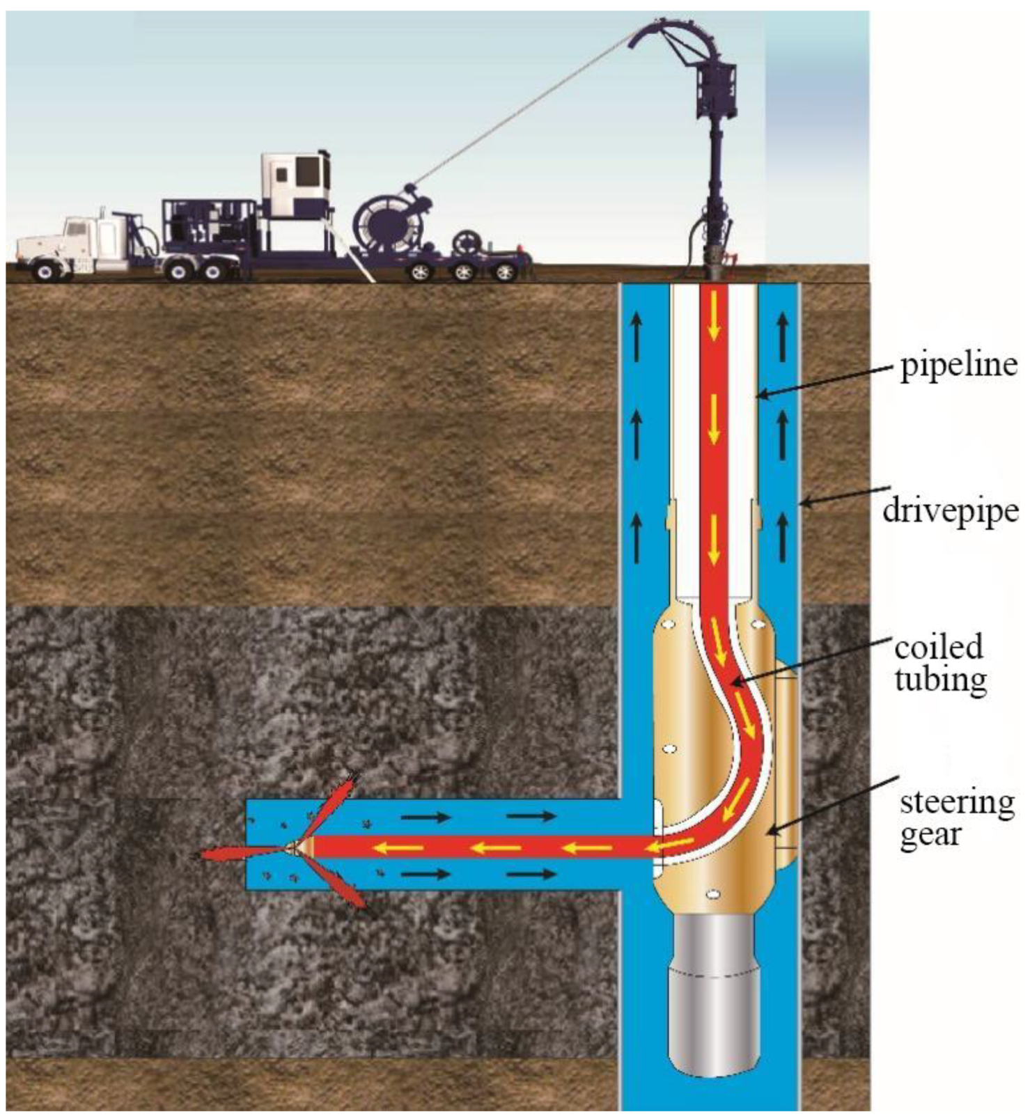
:1. Introduction
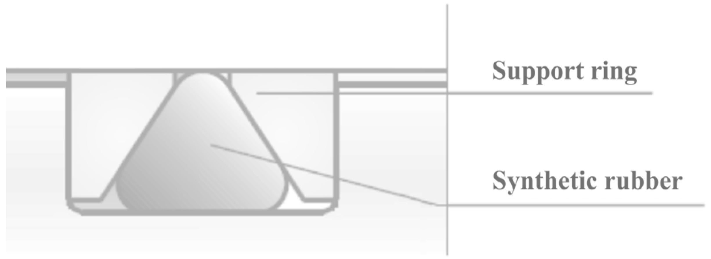
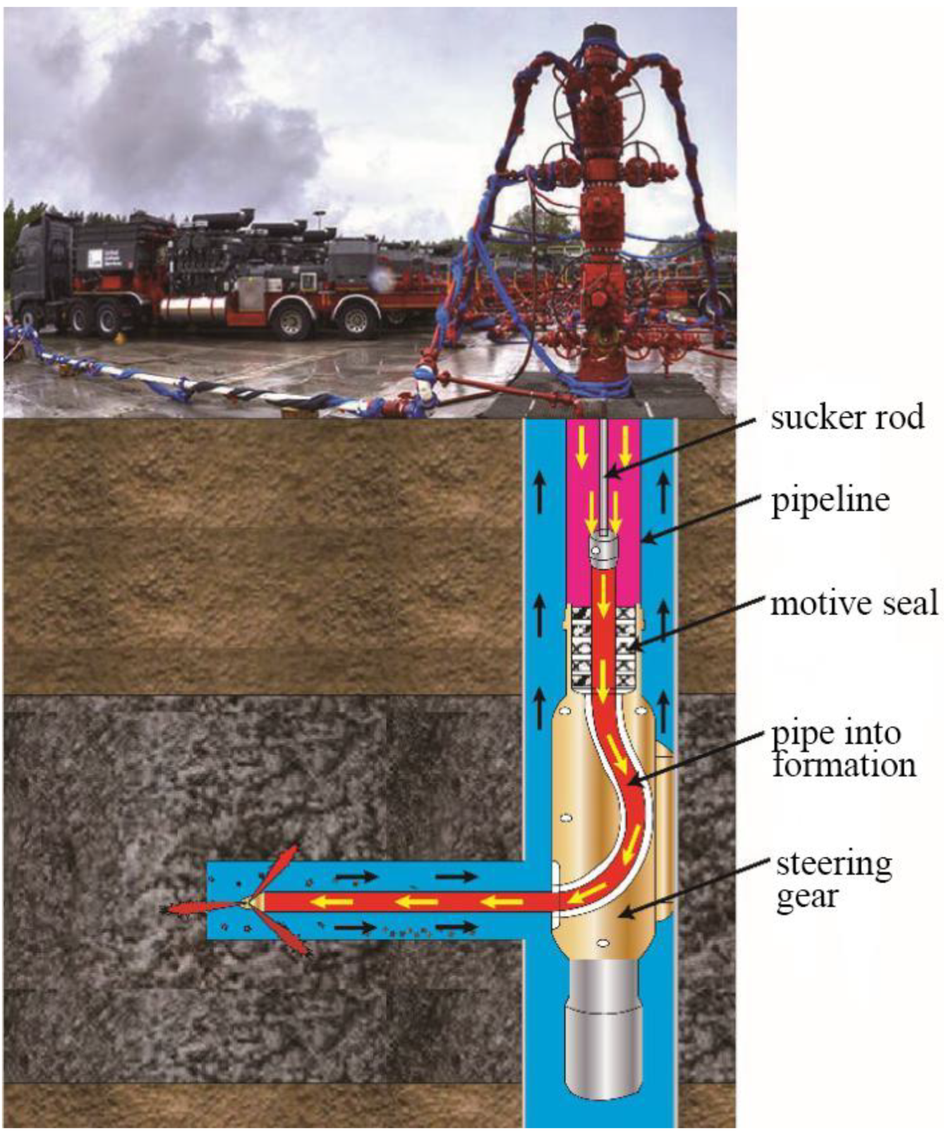
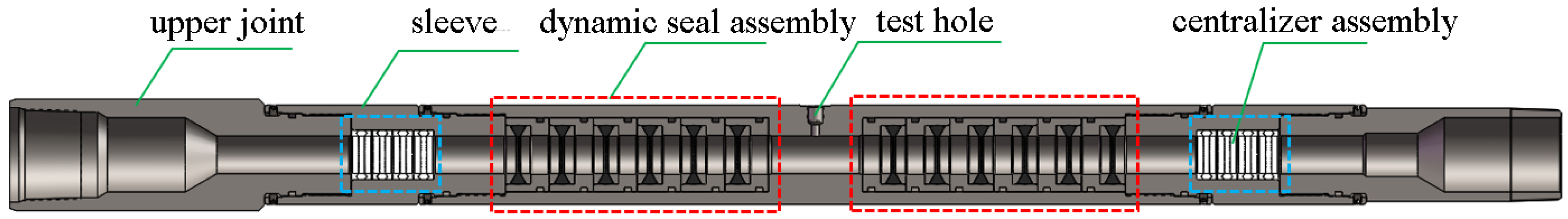
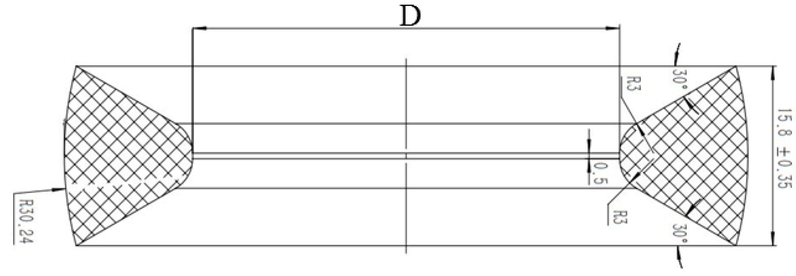
2. Dynamic Seal Structure
3. Numerical Simulation of Sealing Performance
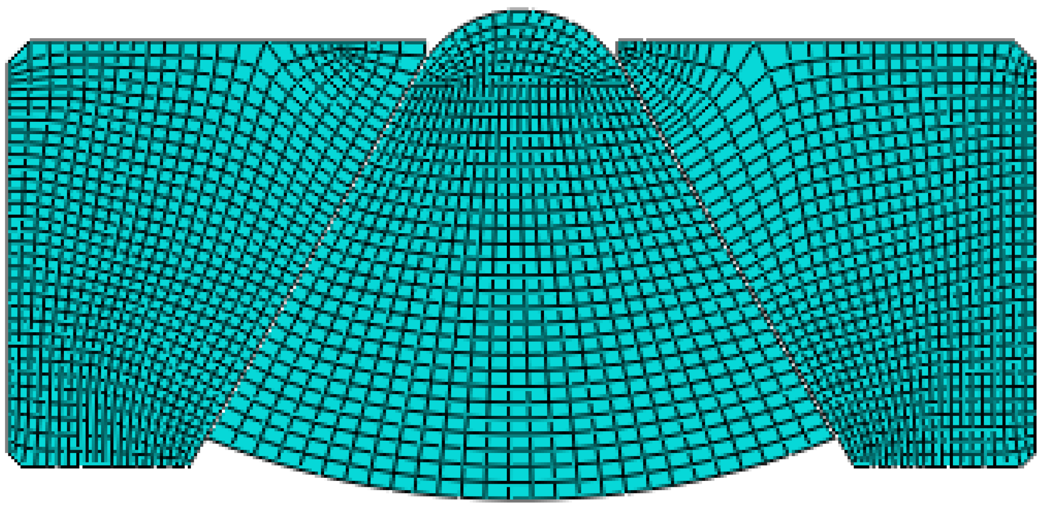
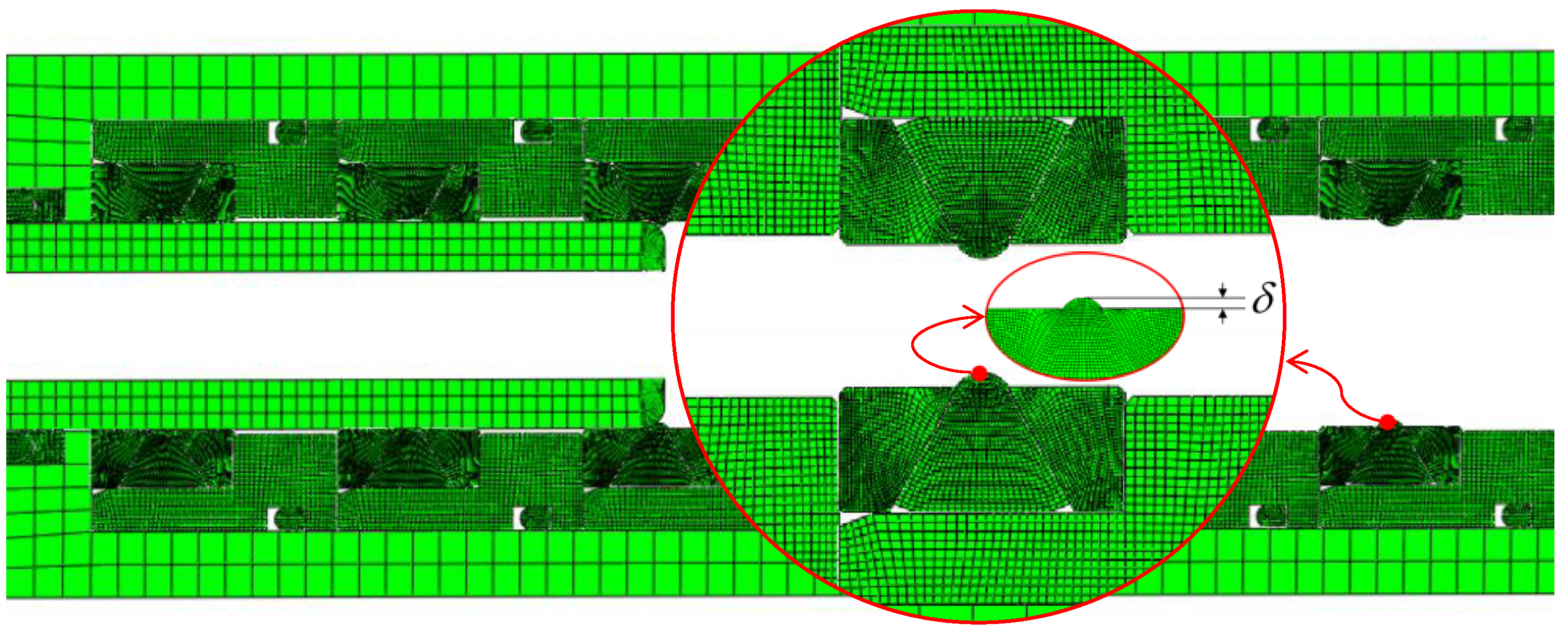
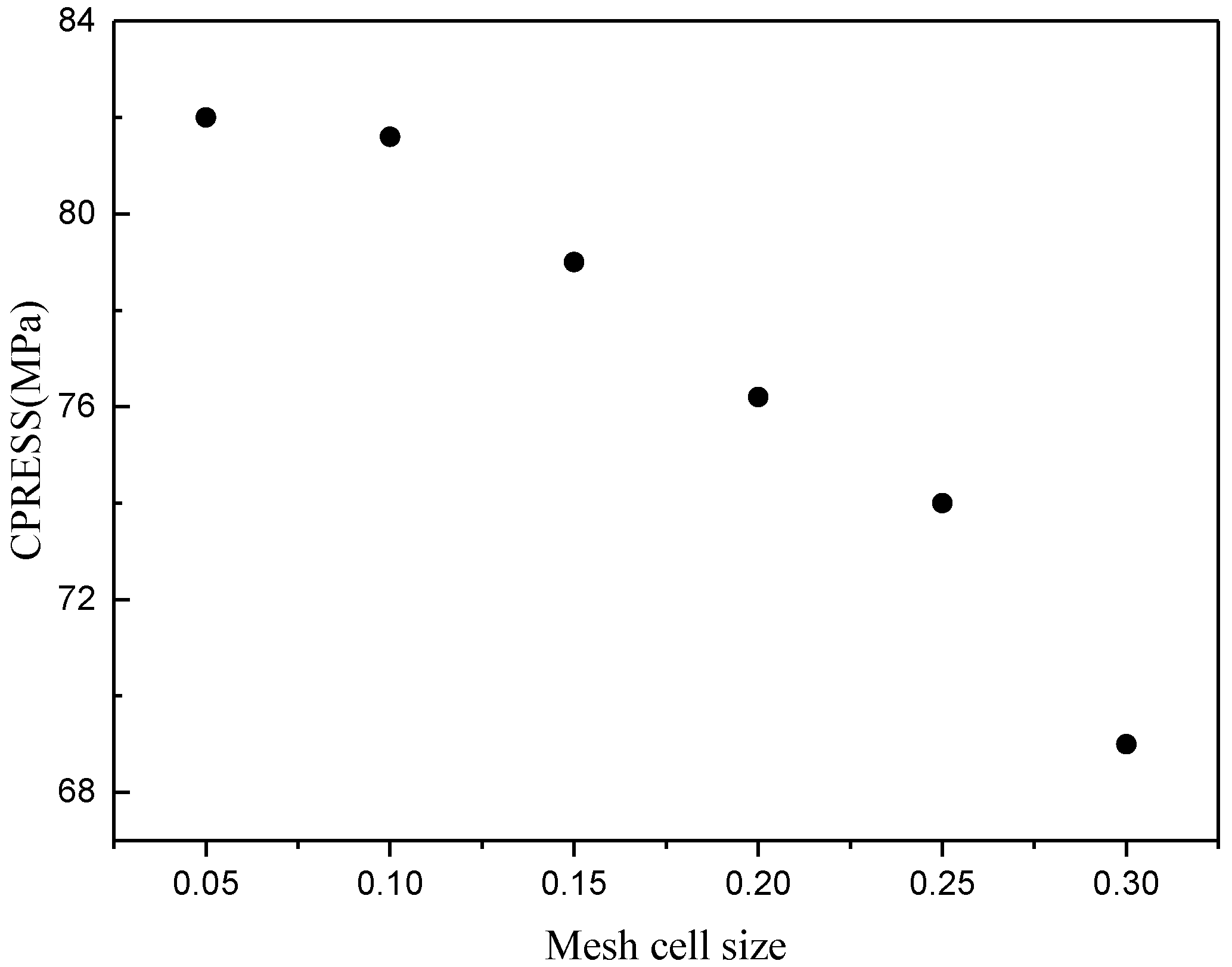
3.1. Finite Element Model
- (1)
- The material had definite elastic modulus and Poisson’s ratio;
- (2)
- The material was continuous and uniform, the creep properties of tension and compression were the same, and the creep did not change volume [29];
- (3)
- The displacement of the smooth rod caused the compression of the triangular seal;
- (4)
- The smooth rod, whose elastic modulus was more significant than rubber material, was analyzed as a rigid body.
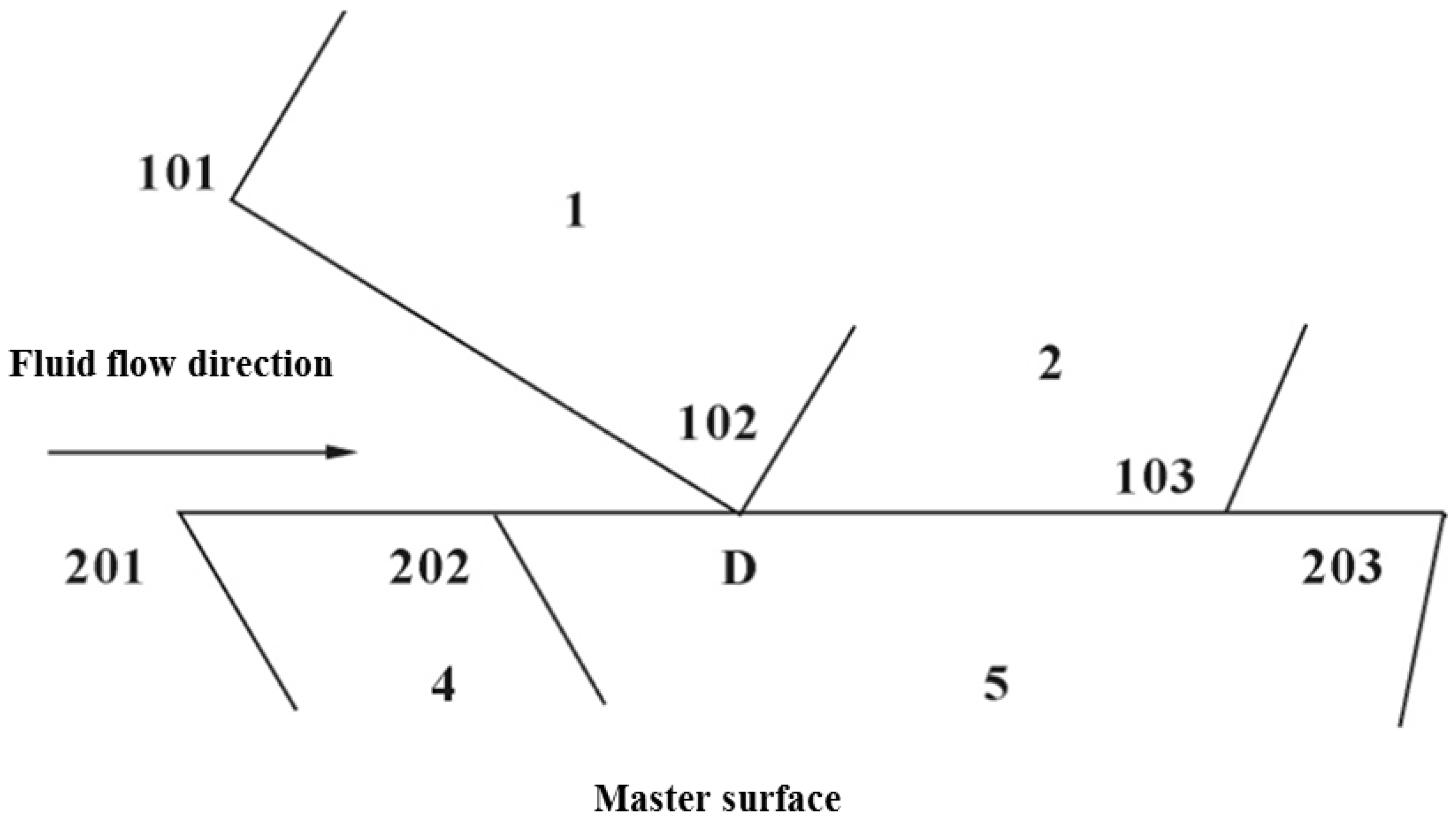
3.2. Boundary Conditions and Loading
3.3. Analysis of Numerical Results
- (1)
- Maximum shear stress: When the seal was subjected to a certain amount of compression and the shear force was more significant than the shear strength, the sealing ring would crack, resulting in shear failure.
- (2)
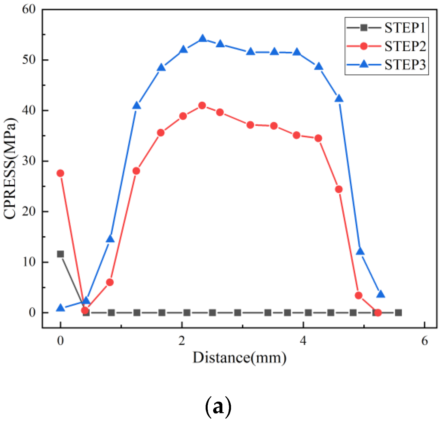
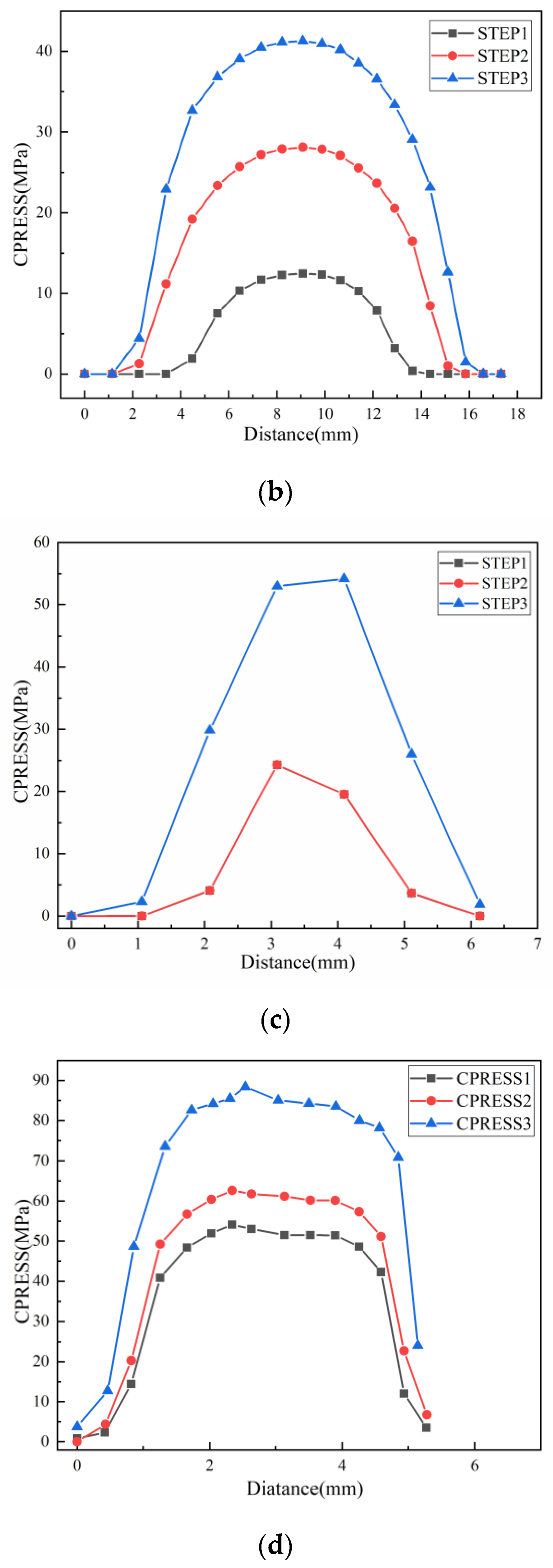
- Maximum contact stress: When the contact stress between the seal and both sides of the contact surface was greater than the pressure value of the fluid, the sealing medium could be realized. Otherwise, leakage would occur, resulting in sealing failure.
- (1)
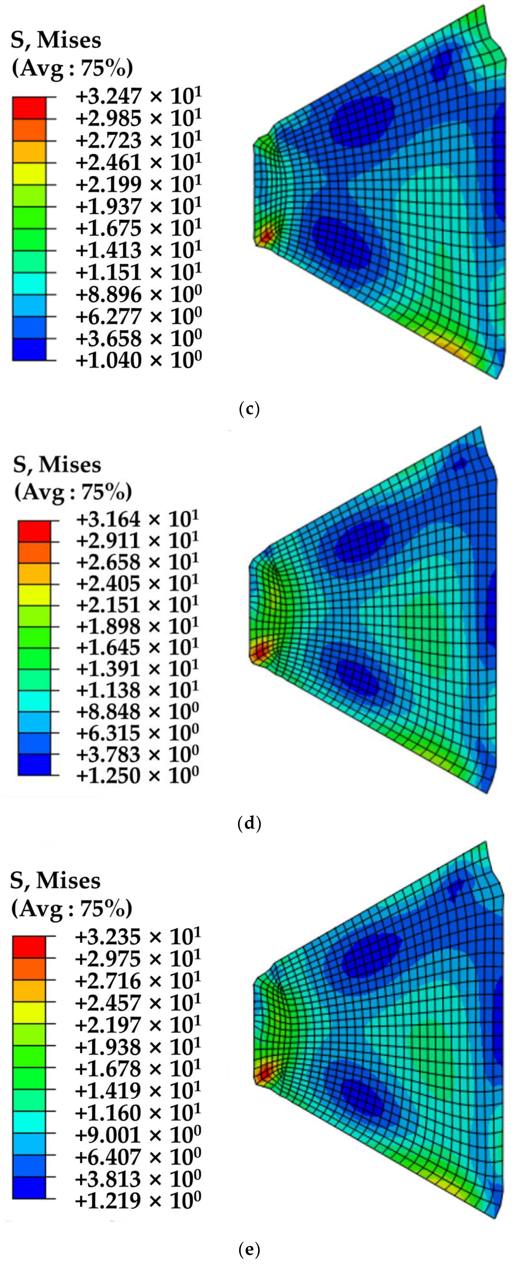
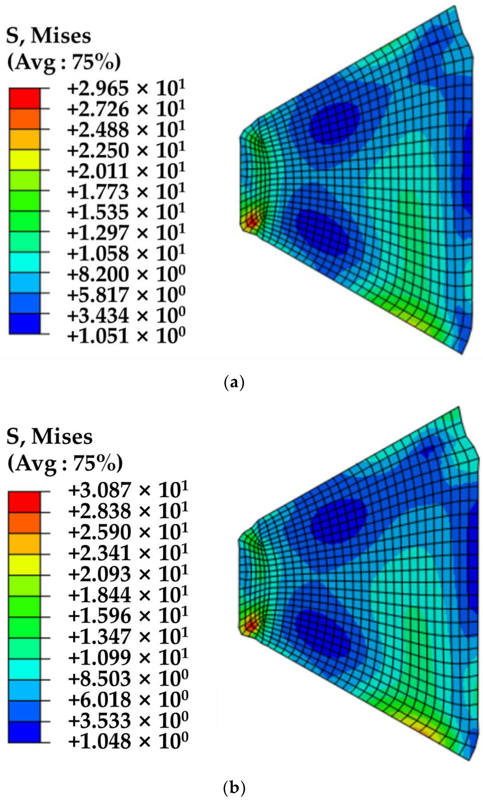
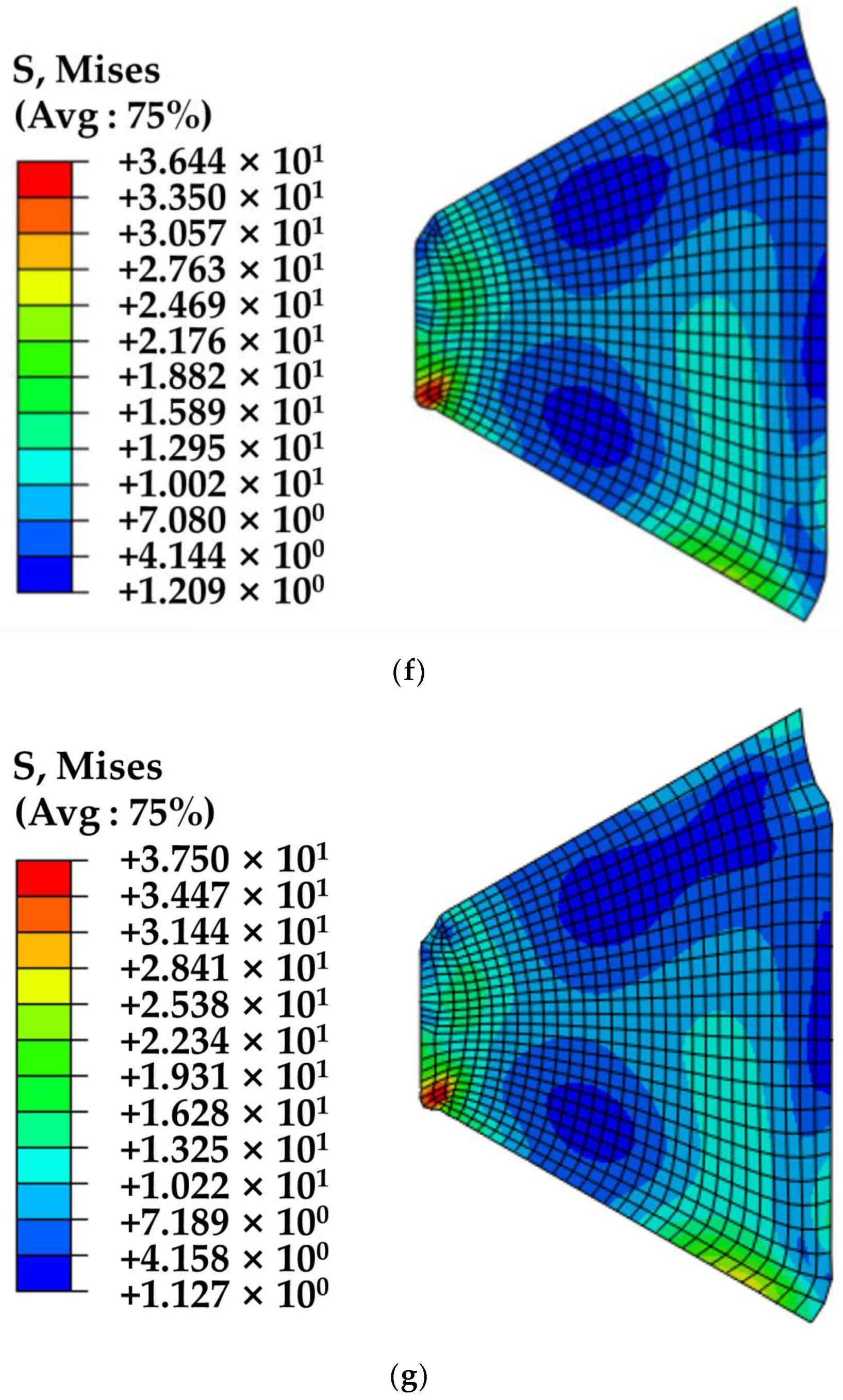
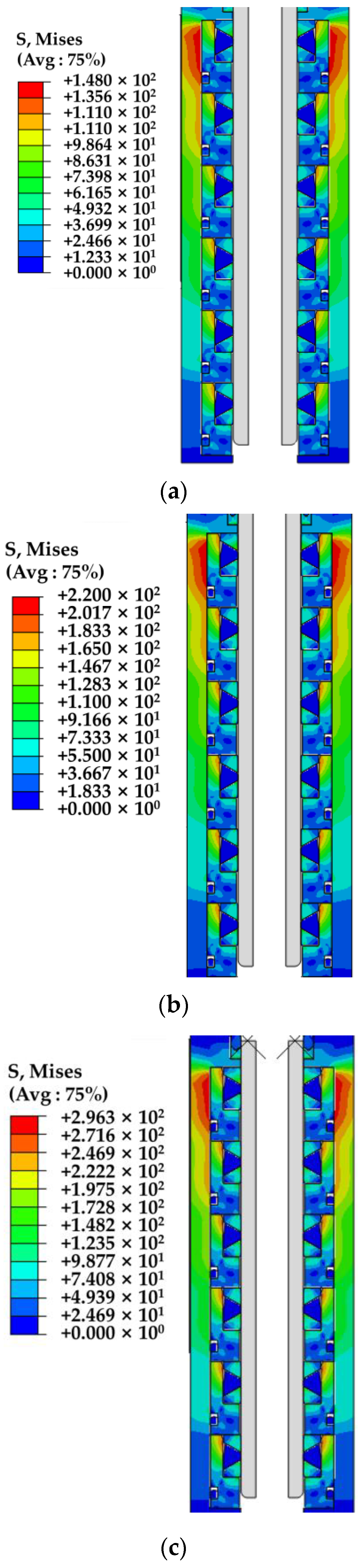
- Under the condition of a certain amount of interference, the von Mises stress of the triangular seal increases with fluid pressure. It can be seen from Figure 12 that the peak position of von Mises stress also changes with the fluid pressure, indicating that the position where the seal may crack changes with the increase in fluid pressure.
- (2)
- Under the constant fluid pressure, with the increase in interference difference, the maximum von Mises stress increases rapidly, the material “stiffness” decreases, and the risk of cracking increases, thus negatively affecting sealing performance and sealing failure. Therefore, the size of the sealing ring should be adjusted appropriately to ensure the seal’s reliability.
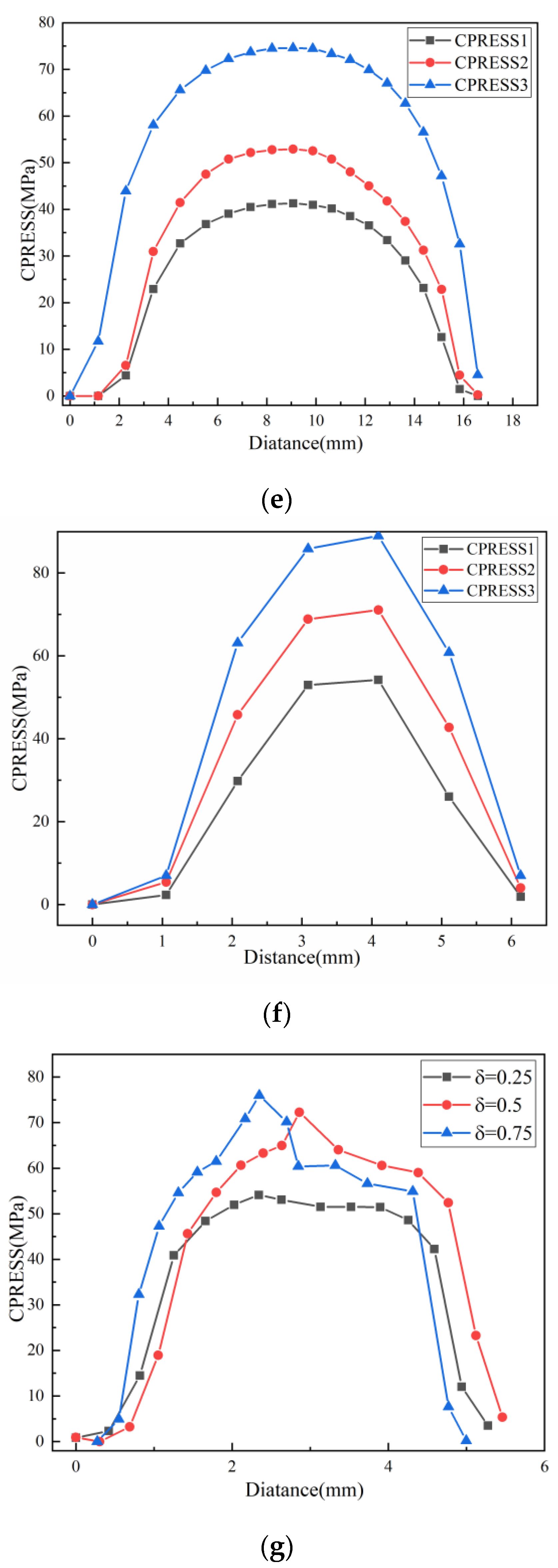
- (3)
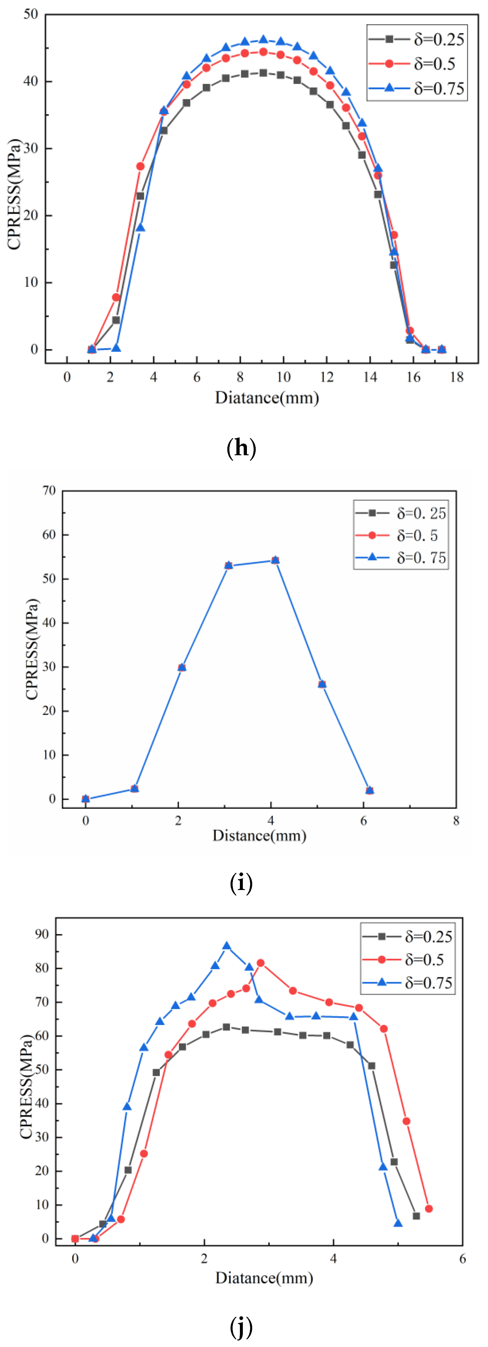
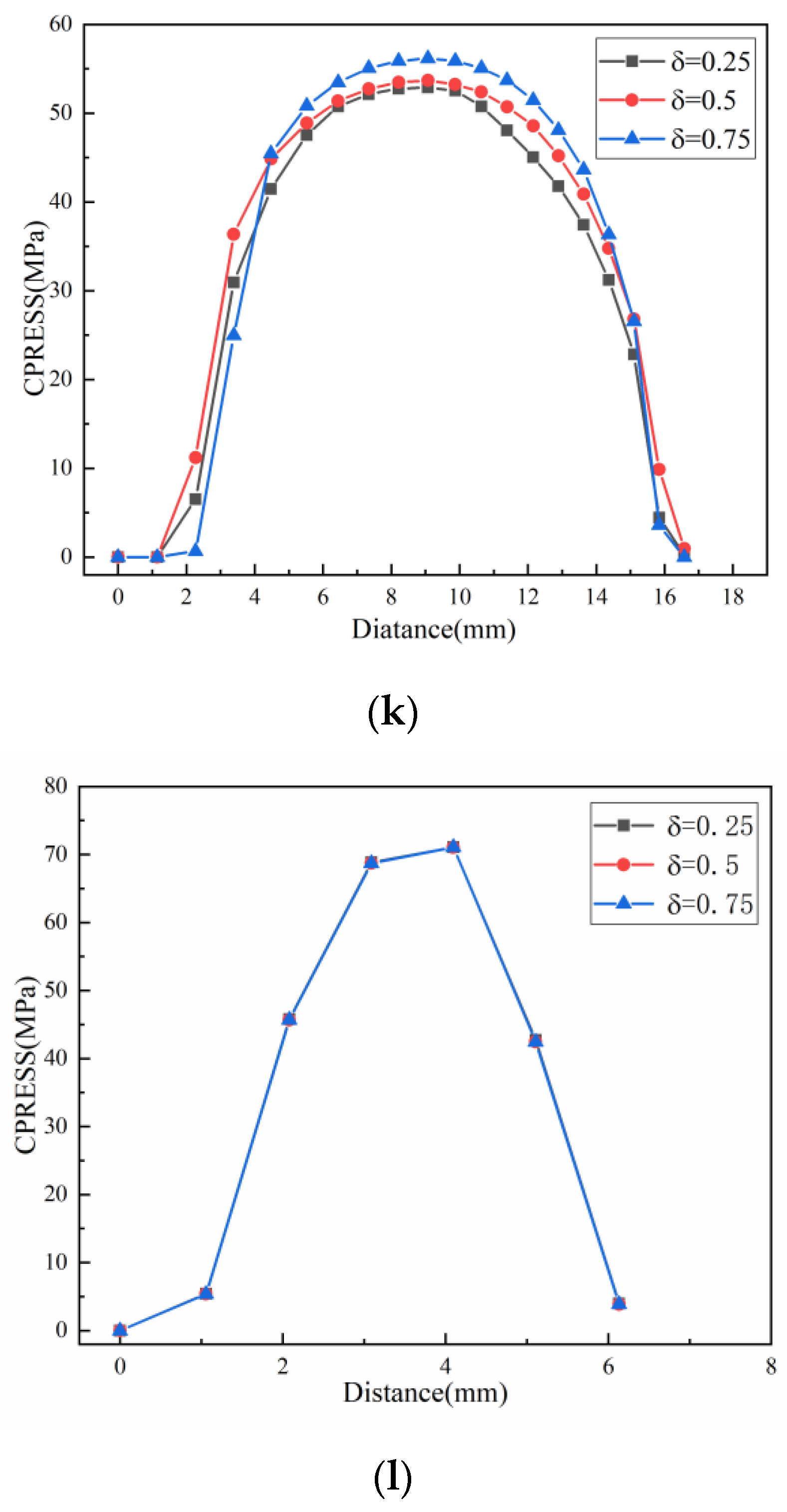
- The maximum contact pressure between the triangular seal and the smooth rod increases with interference and fluid pressure. The maximum contact pressure determines the sealing effect of the triangular seal. Under different high pressures, the maximum contact pressure is always greater than the fluid pressure, which meets the sealing condition and ensures the sealing function of the tool.
4. Dynamic Seal Test
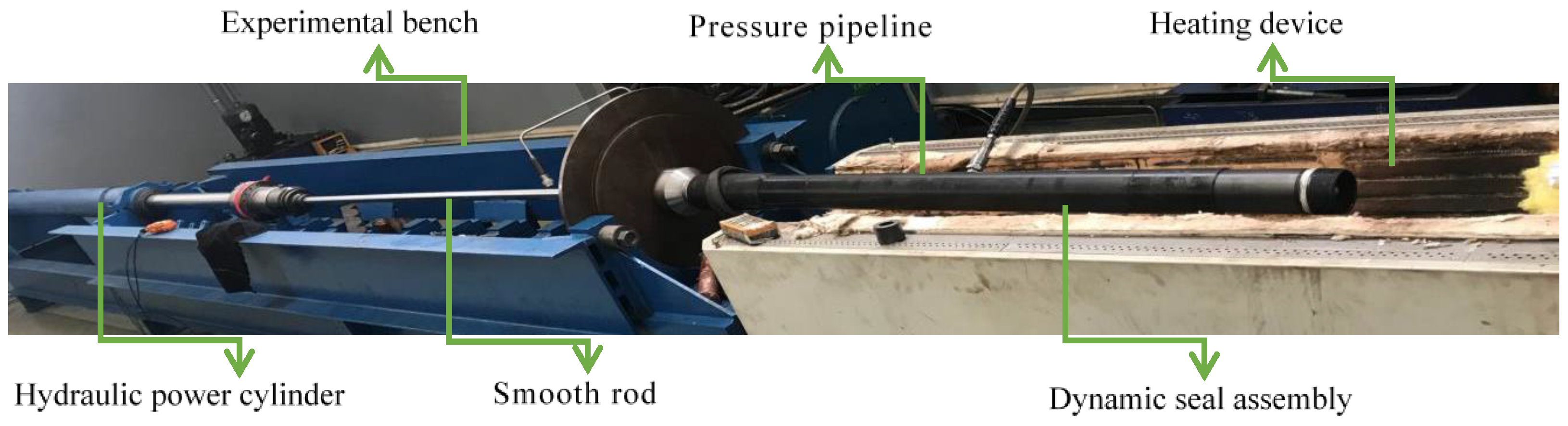
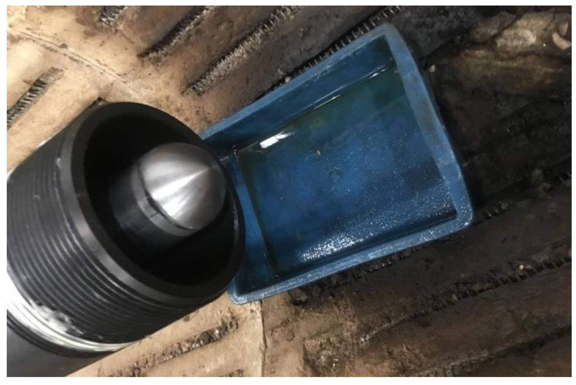
4.1. Experimental Device
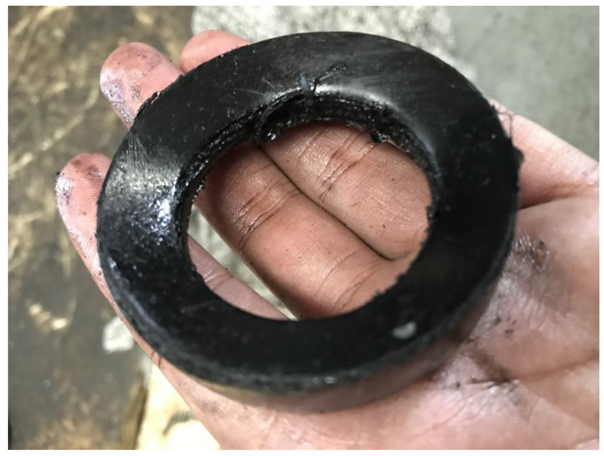
4.2. Wear Resistance Test
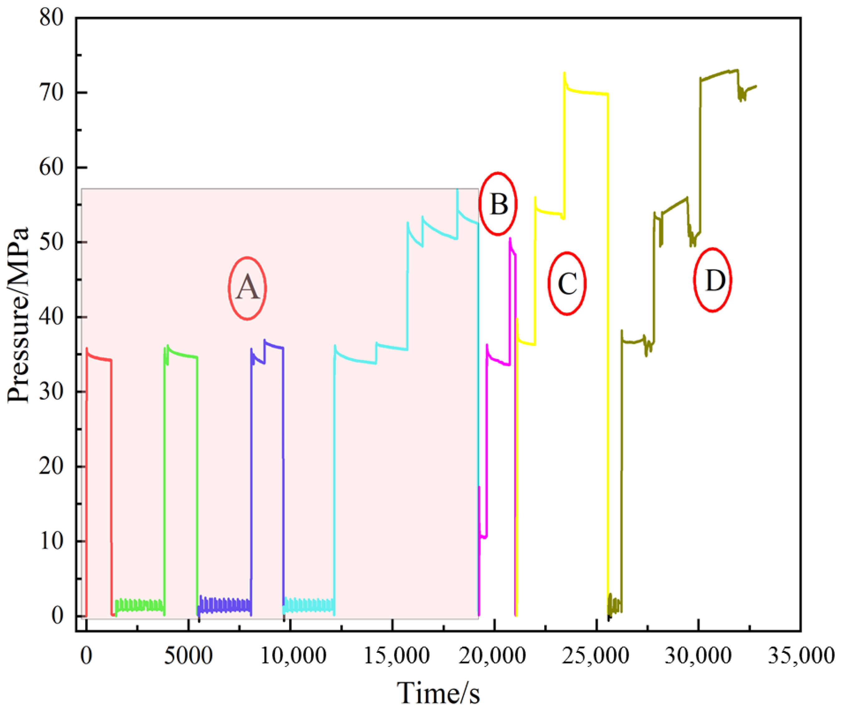
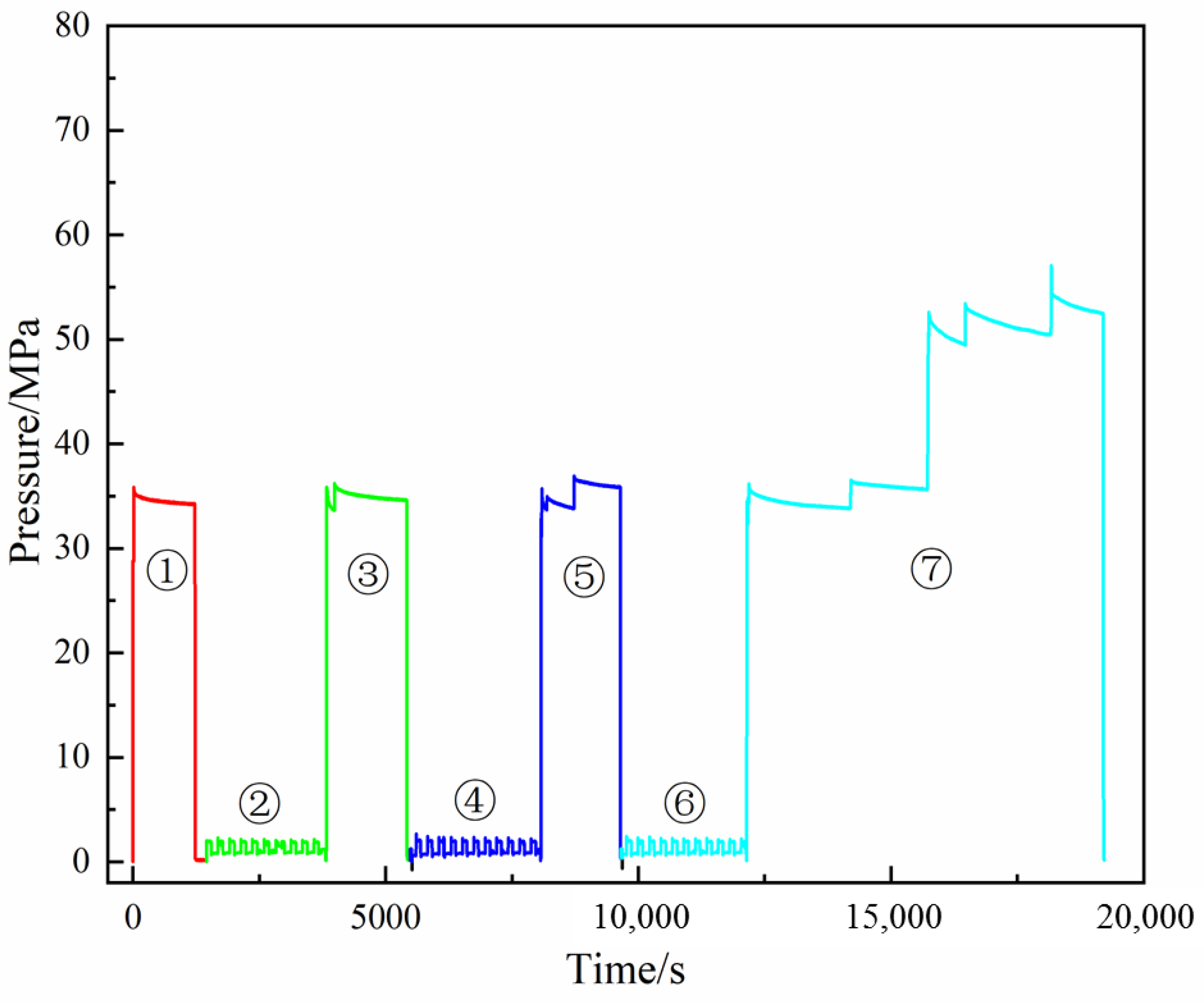
4.3. Movement Resistance Test with Pressure
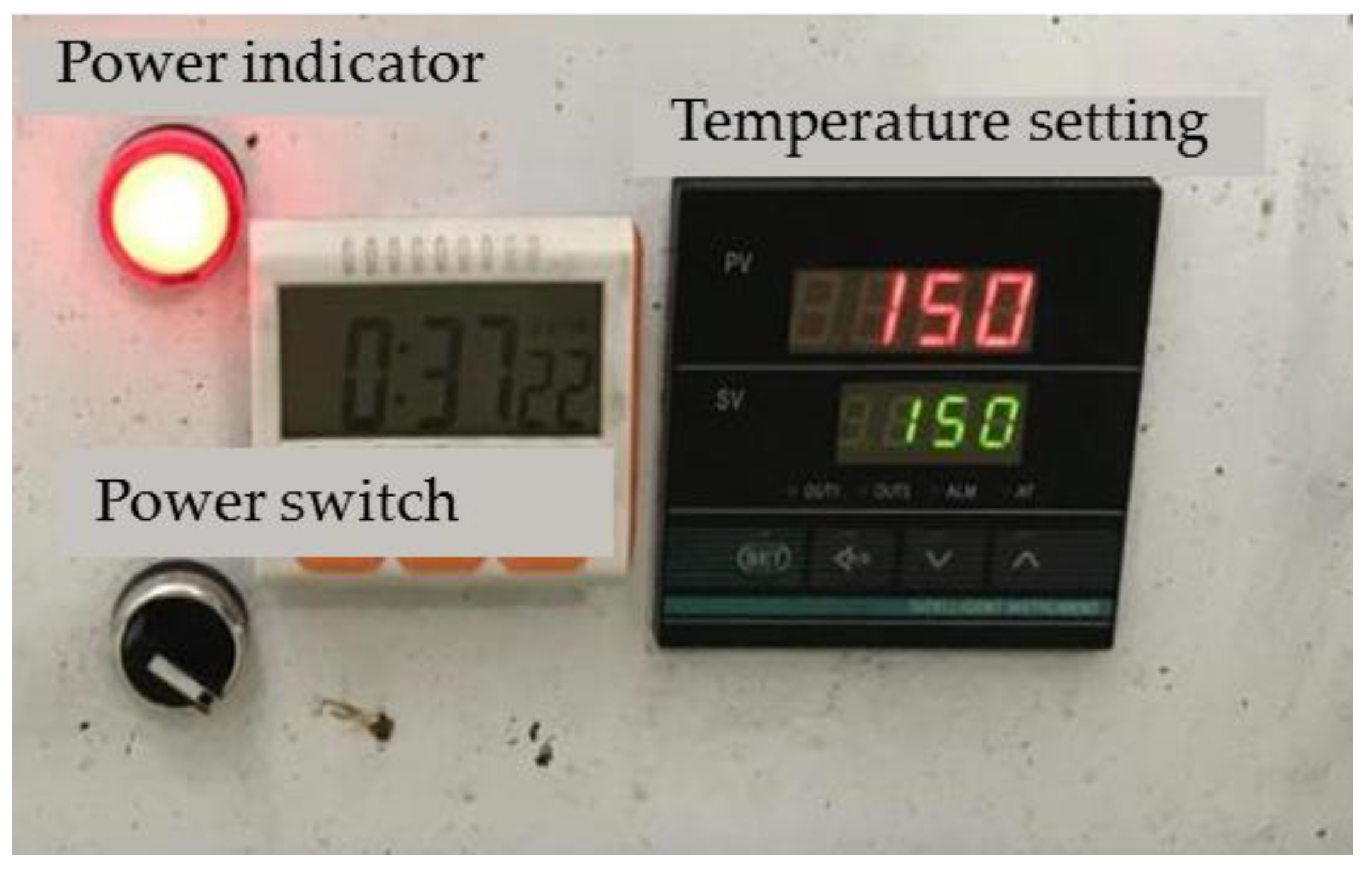
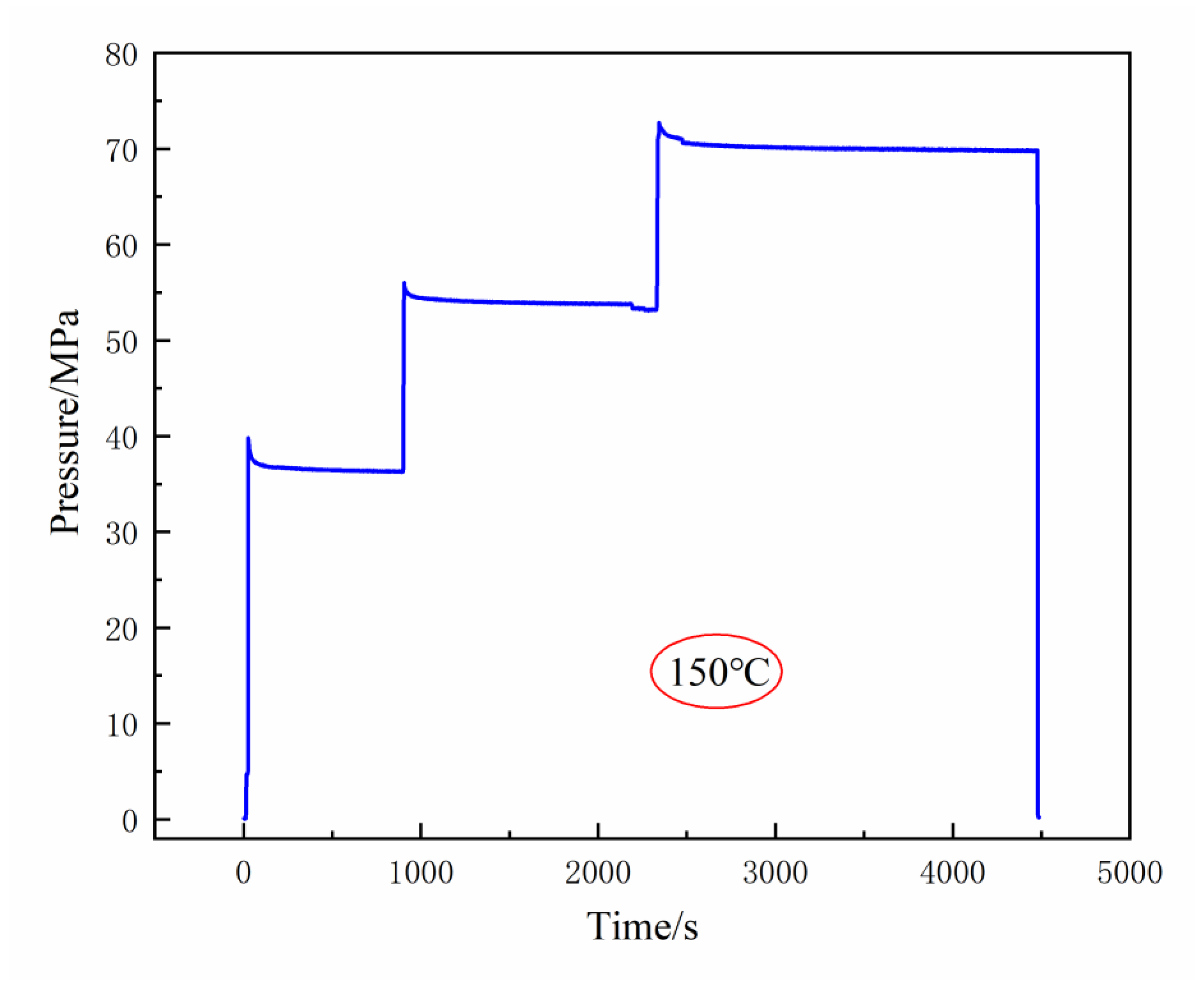
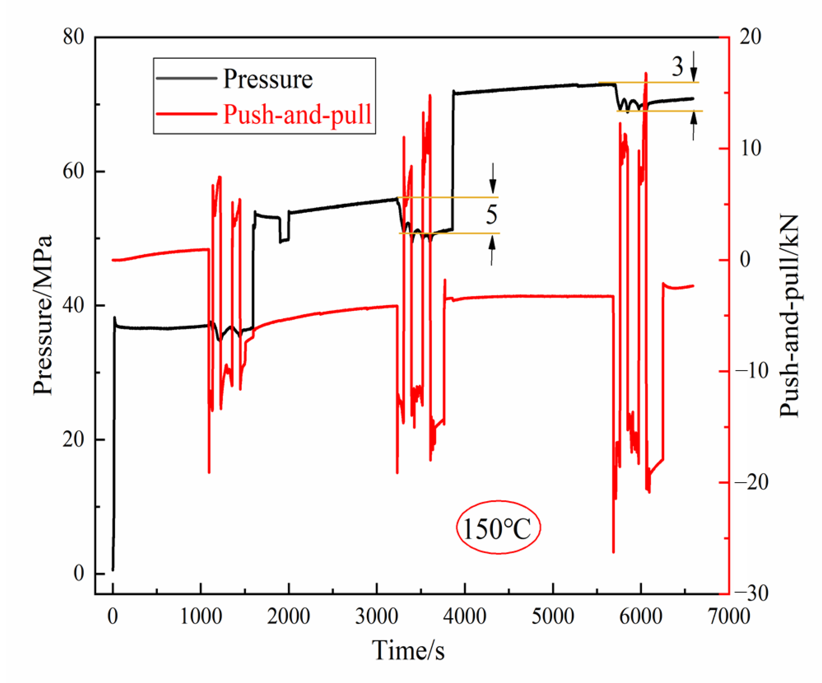
4.4. High-Temperature Pressure Seal Test
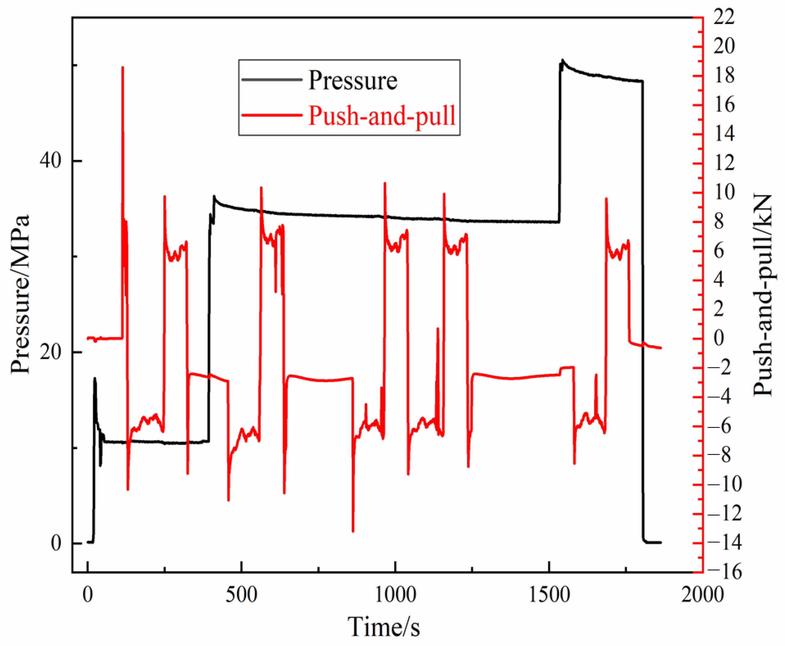
4.5. Movement Resistance Test with Temperate Pressure
5. Conclusions
Author Contributions
Funding
Data Availability Statement
Conflicts of Interest
References
- Deng, L.; Li, W.; Shu, C.X.; Xing, Z. Drilling depth analysis of hydraulic jet radial horizontal well. Sci. J. Intell. Syst. Res. 2021, 3, 31–45. [Google Scholar]
- Wang, B.; Gensheng, L.; Zhongwei, H.; Jingbin, L.; Dongbo, Z.; Hao, L. Hydraulics calculations and field application of radial jet drilling. SPE Drill. Complet. 2000, 31, 71–81. [Google Scholar]
- Huang, Z. Review of radial jet drilling and the key issues to be applied in new geo-energy exploitation. Energy Procedia 2019, 158, 5969–5974. [Google Scholar] [CrossRef]
- Dickinson, W.; Anderson, R.R.; Dickinson, R.W. The ultrashort-radius radial system. SPE Drill. Eng. 1989, 4, 247–254. [Google Scholar] [CrossRef]
- Zhang, S.; Hu, Y.; Li, G.; Tan, W.; Li, J.; Gao, Z.; Zhang, Z. Radial drilling and fracturing technology for short horizontal section of coalbed methane and its application. Coal Sci. Technol. 2016, 44, 50–53. [Google Scholar]
- Zhang, Q.; Liu, H.; Kang, X.; Liu, Y.; Dong, X.; Wang, Y.; Liu, S.; Li, G. An investigation of production performance by cyclic steam stimulation using horizontal well in heavy oil reservoirs. Energy 2021, 218, 119500. [Google Scholar] [CrossRef]
- Dong, Y.; Xu, A.Z. Application of the imitation horizontal well technique in the development of low permeability reservoirs. Adv. Mater. Res. 2013, 734–737, 1350–1353. [Google Scholar]
- Cai, W.B.; Li, Z.M.; Zhang, X.L.; Zhang, B.; Zhang, Q. Horizontal well fracturing technology for reservoirs with low permeability. Pet. Explor. Dev. Online 2009, 36, 80–85. [Google Scholar]
- Xu, Y.; Li, X.; Liu, Q.; Tan, X. Pressure performance of multi-stage fractured horizontal well considering stress sensitivity and dual permeability in fractured gas reservoirs. J. Pet. Sci. Eng. 2021, 201, 108154. [Google Scholar] [CrossRef]
- Best, D.A.; Cordell, G.M.; Hastonm, J.A. Underground test facility: Shaft/Tunnel Labo, ratory for horizontal well technology. J. Pet. Technol. 1987, 39, 603–612. [Google Scholar] [CrossRef]
- Zhang, W.; Duan, T.; Li, M.; Zhao, H.; Shang, X.; Wang, Y. Architecture characterization of ordovician fault-controlled paleokarst carbonate reservoirs in Tuoputai, Tahe oilfield, Tarim Basin, NW China. Pet. Explor. Dev. 2021, 48, 367–380. [Google Scholar] [CrossRef]
- Zheng, S.; Yang, M.; Kang, Z.; Liu, Z.; Long, X.; Liu, K.; Li, X.; Zhang, S. Controlling factors of remaining oil distribution after water flooding and enhanced oil recovery methods for fracture-cavity carbonate reservoirs in Tahe Oilfield. Pet. Explor. Dev. 2019, 46, 786–795. [Google Scholar] [CrossRef]
- Ding, Z.; Wang, R.; Chen, F.; Yang, J.; Zhu, Z.; Yang, Z.; Sun, X.; Xian, B.; Li, E.; Shi, T.; et al. Origin, hydrocarbon accumulation and oil-gas enrichment of fault-karst carbonate reservoirs: A case study of Ordovician carbonate reservoirs in South Tahe area of Halahatang oilfield, Tarim Basin. Pet. Explor. Dev. 2020, 47, 306–317. [Google Scholar] [CrossRef]
- Qin, G.H.; Gao, X.S.; Yan, Z.L. Analysis of thermal recovery horizontal well drilling technology in Gudong Nine District. Adv. Pet. Explor. Dev. 2015, 1, 111–114. [Google Scholar]
- Tian, S.; Huang, Z.; Li, G.; Lu, P.; Zhang, H.; Wang, T. Laboratory experiments on blockage removing and stimulation of CBM reservoirs by composite pulsating hydraulic fracturing of radial horizontal wells. Nat. Gas Ind. B 2019, 6, 151–158. [Google Scholar] [CrossRef]
- Sun, J. Optimization design of self-propelled hydraulic jet bit for coalbed methane. Int. Core J. Eng. 2020, 3, 46–52. [Google Scholar]
- Fan, S.; Li, Y.X.; Cao, J.Q.; Xie, J.B. Optimization technique in double stepped thin horizontal well. Adv. Mater. Res. 2013, 734–737, 1226–1229. [Google Scholar]
- Jun, Y.; Mingyue, C.; Anle, H.; Weidong, J.; Chong, L. Study and application of hydraulic jet radial drilling in Carbonate Reservoirs. Int. J. Oil Gas Coal Eng. 2018, 6, 96. [Google Scholar] [CrossRef]
- Deshpande, K.; Mirasdar, S.P.; Mhaskar, N.A.; Joshi, R.P. Composite frac plug design optimization for efficient hydraulic fracturing operations. In Proceedings of the SPE Eastern Regional Meeting, Charleston, WV, USA, 15–17 October 2019. [Google Scholar]
- Zhou, Z.; Kanglei, Z.; Jing, L. Finite element analysis of stress and contact pressure of O-ring. Lubr. Seal. 2006, 4, 86–89. [Google Scholar]
- Jung, J.K.; Kim, I.G.; Kim, K.T.; Ryu, K.S.; Chung, K.S. Evaluation techniques of hydrogen permeation in sealing rubber materials. Polym. Test. 2021, 93, 107016. [Google Scholar] [CrossRef]
- Zhou, C.; Chen, G.; Liu, P. Finite element analysis of sealing performance of rubber D-ring seal in high-pressure hydrogen storage vessel. J. Fail. Anal. Prev. 2018, 18, 846–855. [Google Scholar] [CrossRef]
- Huang, Y.; Li, Y.; Zhao, H.; Wen, H. Research on constitutive models of hydrogenated nitrile butadiene rubber for packer at different temperatures. J. Mech. Sci. Technol. 2020, 34, 155–164. [Google Scholar] [CrossRef]
- Hu, G.; Zhang, P.; Wang, G.; Zhang, M.; Li, M. The influence of rubber material on sealing performance of packing element in compression packer. J. Nat. Gas Sci. Eng. 2017, 38, 120–138. [Google Scholar] [CrossRef]
- Huang, P.; Wang, Y.S.; Li, Y.; Tao, J.Y. Analysis of low temperature compression characteristics of rubber seal strip of shelter based on ABAQUS. IOP conference series. Mater. Sci. Eng. 2021, 1043, 32050. [Google Scholar]
- Zhou, S.M.; Chen, P.; Shi, Y. Analysis on sealing performance for a new type of rubber saddle-shaped sealing ring based on AQAQUS. Procedia Eng. 2015, 130, 1000–1009. [Google Scholar] [CrossRef]
- Zhu, J.; Zou, L.Q.; Han, S.J. The modeling of rubber sealing ring of fluid dynamic pressure and finite element analysis about stress based on SolidWorks and ANSYS. Appl. Mech. Mater. 2012, 215–216, 1246–1249. [Google Scholar]
- Zheng, C.; Zheng, X.; Qin, J.; Liu, P.; Aibaibu, A.; Liu, Y. Nonlinear finite element analysis on the sealing performance of rubber packer for hydraulic fracturing. J. Nat. Gas Sci. Eng. 2021, 85, 103711. [Google Scholar] [CrossRef]
- Lee, B.S.; Rivin, E.I. Finite element analysis of load-deflection and creep characteristics of compressed rubber components for vibration control devices. J. Mech. Des. 1996, 3, 328–336. [Google Scholar] [CrossRef]
- Yi, T.; Weng, X.; Zhu, S. Static performance analysis of incompressible rubber body. J. Nav. Univ. Eng. 2002, 1, 76–80. [Google Scholar]
- Abdelal, G.F.; Robotham, A.; Carragher, P. Numerical simulation of a patent technology for sealing of deep-sea oil wells using nonlinear finite element method. J. Pet. Sci. Eng. 2015, 133, 192–200. [Google Scholar] [CrossRef]
- Kim, C.; Shim, W. Analysis of contact force and thermal behaviour of lip seals. Tribol. Int. 1997, 2, 113–119. [Google Scholar]
- Chen, T.; Ma, W.; Liu, S.; Wu, J. Analysis on mechanical influencing factors of fatigue behavior for the packer on pipe ram in snubbing unit. Eng. Fail. Anal. 2019, 103, 20–31. [Google Scholar] [CrossRef]
- Zhang, F.; Shui, H.; Yang, J. Sealing performance and fatigue life of the fracturing packer rubber of various materials. Proc. Inst. Mech. Eng. Part C J. Mech. Eng. Sci. 2019, 233, 6157–6166. [Google Scholar] [CrossRef]
- Dong, L.; Li, K.; Zhu, X.; Li, Z.; Zhang, D.; Pan, Y.; Chen, X. Study on high temperature sealing behavior of packer rubber tube based on thermal aging experiments. Eng. Fail. Anal. 2020, 108, 104321. [Google Scholar] [CrossRef]
- Liu, Y.; Lian, Z. Failure analysis on rubber sealing structure of mandrel hanger and improvement in extreme environments. Eng. Fail. Anal. 2021, 125, 105433. [Google Scholar] [CrossRef]


| Material | Density (g/mm3) | Elastic Modulus (MPa) | Poisson’s Ratio |
|---|---|---|---|
| G4140 | 7.83 × 10⁹ | 200,000 | 0.29 |
| PEEK | 1.304 × 10⁹ | 4600 | 0.38 |
| NHBR | 1 × 10⁹ | — | — |
| Interference (mm) | Maximum von Mises Stress (MPa) | ||
|---|---|---|---|
| 35 | 52 | 70 | |
| 0.25 | 29.65 | 30.87 | 32.47 |
| 0.5 | 31.64 | 32.35 | — |
| 0.75 | 36.44 | 37.50 | — |
Disclaimer/Publisher’s Note: The statements, opinions and data contained in all publications are solely those of the individual author(s) and contributor(s) and not of MDPI and/or the editor(s). MDPI and/or the editor(s) disclaim responsibility for any injury to people or property resulting from any ideas, methods, instructions or products referred to in the content. |
© 2024 by the authors. Licensee MDPI, Basel, Switzerland. This article is an open access article distributed under the terms and conditions of the Creative Commons Attribution (CC BY) license (https://creativecommons.org/licenses/by/4.0/).
Share and Cite
Chai, L.; Liu, Y.; Chen, G.; Sun, Q.; Gao, W.; Dou, Z. Reliability Analysis of Dynamic Sealing Performance in the Radial Hydraulic Drilling Technique. Processes 2024, 12, 807. https://doi.org/10.3390/pr12040807
Chai L, Liu Y, Chen G, Sun Q, Gao W, Dou Z. Reliability Analysis of Dynamic Sealing Performance in the Radial Hydraulic Drilling Technique. Processes. 2024; 12(4):807. https://doi.org/10.3390/pr12040807
Chicago/Turabian StyleChai, Lin, Yongsheng Liu, Guoqiang Chen, Qiang Sun, Wenlong Gao, and Zijun Dou. 2024. "Reliability Analysis of Dynamic Sealing Performance in the Radial Hydraulic Drilling Technique" Processes 12, no. 4: 807. https://doi.org/10.3390/pr12040807
APA StyleChai, L., Liu, Y., Chen, G., Sun, Q., Gao, W., & Dou, Z. (2024). Reliability Analysis of Dynamic Sealing Performance in the Radial Hydraulic Drilling Technique. Processes, 12(4), 807. https://doi.org/10.3390/pr12040807