Article

Two-Step Intelligent Control for a Green Flexible EV Energy Supply Station Oriented to Dual Carbon Targets

1
State Grid Shanghai Municipal Electric Power Company Electric Power Research Institute, Shanghai 200437, China
2
College of Automation Engineering, Shanghai University of Electric Power, Shanghai 200090, China
*
Author to whom correspondence should be addressed.
Processes 2021, 9(11), 1918; https://doi.org/10.3390/pr9111918
Submission received: 13 September 2021 / Revised: 15 October 2021 / Accepted: 22 October 2021 / Published: 27 October 2021
(This article belongs to the Special Issue Integrated Energy Systems towards Carbon Neutrality)

Abstract

:
As China proposes to achieve carbon peak by 2030 and carbon neutrality by 2060, as well as the huge pressure on the power grid caused by the load demand of the energy supply stations of electric vehicles (EVs), there is an urgent need to carry out comprehensive energy management and coordinated control for EVs’ energy supply stations. Therefore, this paper proposed a two-step intelligent control method known as ISOM-SAIA to solve the problem of the 24 h control and regulation of green/flexible EV energy supply stations, including four subsystems such as a photovoltaic subsystem, an energy storage subsystem, an EV charging subsystem and an EV battery changing subsystem. The proposed control method has two main innovations and contributions. One is that it reduces the computational burden by dividing the multi-dimensional mixed-integer programming problem of simultaneously optimizing the 24 h operation modes and outputs of four subsystems into two sequential tasks: the classification of data-driven operation modes and the rolling optimization of operational outputs. The other is that proper carbon transaction costs and carbon emission constraints are considered to help save costs and reduce carbon emissions. The simulation analysis conducted in this paper indicates that the proposed two-step intelligent control method can help green/flexible EV energy supply stations to optimally allocate energy flows between four subsystems, effectively respond to peak shaving and valley filling of power grid, save energy costs and reduce carbon emissions.

1. Introduction

With the increasingly prominent problems of environmental pollution and fossil fuel depletion, countries all over the world have designed different low-carbon development routines. Among them, China proposed a dual-carbon target to achieve carbon peak by 2030 and carbon neutrality by 2060. In China, energy carbon emissions account for about 80% of total carbon emissions. Therefore, the core task of China’s dual-carbon target is to promote low-carbon energy transition and revolutions, and the essential measures are to reduce fossil energy consumption and increase the proportion of renewable energy. In the field of transportation, the replacement of fuel vehicles is an inevitable trend for electric vehicles (EVs). In 2020, the stock of EVs in China was 4.5 million, more than twice the stock in 2018 [1]. The development of EVs in China is affected by mileage, cost and policy impact. Small electrical cars, E-vans and electric buses are three typical types of EV. Small electric cars are very much in line with people’s daily travel needs, especially in rural markets and third- and fourth-tier cities in China. China’s E-vans offer some leading advantages in terms of industrialization and have made great progress in their product development, market expansion and application. For example, the JD company proposes to replace all its trucks with pure electric vehicles in the next five years, and the self-built logistics industry, led by the e-commerce sector, is gradually replacing traditional fuel trucks with pure electric trucks. Therefore, with the guidance of national policies in relation to the satisfaction of end-market demand, E-vans will have a very large development space in the future. Electric buses are the main route of China’s new energy vehicles. It is reported that Shenzhen, China took the lead in realizing 100% pure electrification of urban buses in 2017. At this stage, when the on-board power supply, power, driving range, charging speed and charging capacity tend to be mature, popularizing pure electric buses to the whole country is not only an important measure to help save energy and reduce emissions, but also a key step to promote the development of the urban public transport industry.
However, the daily energy supply demand of EVs has obvious peak–valley effects, which increases the difficulty of peak shaving and valley filling within the power grid. There are two options for the energy supply of EVs: charging and battery changing. In China, EVs’ charging piles can be seen in both public parking lots and special charging stations, while shorter EVs’ battery changing services can only be provided by special battery changing stations. In order to meet the needs of different EV users as well as increasing operational flexibility through low-carbon measures, some EVs’ energy supply stations provide charging and battery changing services simultaneously, and are also equipped with photovoltaic systems and energy storage devices. These kinds of multi-functional green/flexible EV energy supply stations are referred to as EV “Photovoltaic-Storage-Charging-Change” stations.
The organic combination of photovoltaic-storage-charging-change systems can help solve the problem of the insufficient power distribution capacity of EVs’ energy supply stations, reduce the impact on the power grid, and also increase renewable energy utilization. However, due to the system’s complexity, the 24 h daily optimal control and regulation of the “Photovoltaic-Storage-Charging-Change” stations for EVs, considering additional carbon emission constraints, is relatively difficult, which is mainly shown in the following aspects:
  • The 24 h daily control and regulation problem of simultaneously optimizing operation modes and outputs for four subsystems is a mixed-integer programming problem [2], which should solve two issues. One is to determine the operation mode of each subsystem for all 24 h of a day, and the other is to determine the best output of each subsystem.
  • The dynamic characteristics of distributed energy sources including photovoltaic, energy storage, charging and battery changes in the EVs’ “Photovoltaic-Storage-Charging-Change” stations are different from each other in terms of time-scale, and are mostly nonlinear and multi-dimensional. This increases the complexity of the optimization control and regulation problem.
  • There are coupling and restriction relationships between different subsystems, which also increases their complexity.
  • Additional carbon transaction costs and carbon emission constraints also increase the complexity.
Existing research studies that are relevant to the aforementioned optimization problem of regulation and control are generally divided into two categories: artificial intelligence algorithms and analytical methods.
On the one hand, artificial intelligence algorithms, including the particle swarm and genetic algorithm, are widely used to solve distributed energy control problems with non-convex characteristics and nonlinearity [3]. Jha, M., et al. proposed a multiport converter for integrating the PV, charging docks, and energy storage device (ESD) with the grid, and proposed an intelligent energy management system by adapting particle swarm optimization for efficient switching between the sources [4]. Improved methods such as the swarm optimization searcher [5], gravitational search algorithm [6], and particle swarm algorithm [7], with time-varying acceleration constant iteration, etc., are also applied to the optimization of distributed energy sources. In addition, deep learning and other intelligent algorithms are used by some researchers to solve the problem. For example, Ndiaye, El Hadji Mbaye, et al. proposed an intelligent algorithm based on adaptive neuro-fuzzy inference system to control a photovoltaic generator (PVG) connected to a load and a battery, which allows the PV system to function normally by charging and discharging the battery whatever the weather conditions [8]. Qu Kaiping, et al. used the interior point method and the knowledge transfer Q algorithm to form a cascade algorithm to deal with the non-convex energy equation of the distributed energy network [9]. Liu Xiaokang took the generalized heterogeneous multi-agent system as the object, carried out research on two aspects of cooperative control and its application in the DC microgrid, and designed an optimal power control strategy based on reinforcement learning [10]. MyungJae Shin, et al. proposed a multi-agent-based energy management deep reinforcement learning method, established a distributed power generation model for EV charging stations containing photovoltaic systems and energy storage systems, and obtained a targeted power load dispatching plan to reduce operating costs [11].
One the other hand, two types of analytical methods are involved in this research field: the stepwise decomposition solution and the unified solution. The stepwise decomposition solution mainly optimizes and solves each independent subsystem, and then couples the information of each system, and finally iteratively solves the optimal solution that satisfies the conditions. The unified solution starts from the overall model, and uses linearization-related techniques to approximate the original optimization problem to a mixed integer programming or linear programming problem, which mainly includes methods such as 0-1 variables and convex relaxation techniques. Given that EV energy supply stations are connected to the power grid, some researchers used hierarchical control, improved droop control [12] or sequence arrangement control strategies [13], distributed algorithms, consensus algorithms [14], and heuristic algorithms [15] to guide the charging load of EV energy supply stations. Researchers who were focused on system frequency stability realized overall load variance and charging cost reduction in [16,17], and realized peak shaving and valley filling in [18,19]. Meng Chao, et al. aimed at the collaborative control problem of nonlinear multi-agent systems. They proved that followers can approach the leader’s output infinitely, not only meeting the predetermined performance but also keeping the error within the specified range with high accuracy [20]. In the EV to grid(V2G) area, combined with the charging load model and the charging optimization model, some researchers formulated multi-agent charging management model [21], and built a dynamic multi-agent collaboration framework [22,23]. With the idea of aggregation, a model was constructed through dynamic programming algorithms [24] and probability statistics [25] to ensure an optimal balance between charging costs and grid revenue. Other researchers also focus on the configuration of multiple energy sources. In [26], Vavilapalli, S., et al. proposed a Power Balancing Control (PBC) method for the configuration of a grid energy storage system for photo voltaic (PV) applications with three different power sources to operate the system in three different modes of operation, and conducted a Hardware-In-the-Loop (HIL) simulation to prove the effectiveness of the proposed PBC algorithm.
To sum up, there have been many researches contributing to the optimization of configuration, energy management and real-time control of integrated energy systems with multiple energy sources. Generally, most studies focus on theoretical research, and the effectiveness of the proposed methods in these studies are mainly verified by simulations. In this paper, a real pilot green/flexible EV “Photovoltaic-Storage-Charging-Change” energy supply station in Shanghai, China is taken as the research object. To solve the realistic 24 h daily optimal control and regulation problem of the green/flexible EV “Photovoltaic-Storage-Charging-Change” station as well as supporting the dual carbon target, a two-step intelligent control method referred to as ISOM-SAIA is proposed in this paper. The proposed ISOM-SAIA algorithm is a combination of a data-driven intelligent classification method for improving a self-organizing map (SOM) proposed in [27] and a rolling optimization method for combining the simulated annealing method (SA) [28,29] and the immune algorithm (IA) [30,31,32]. It classifies the operation modes of all subsystems, for each hour, by ISOM in the first step, and then calculates the optimal operation outputs of all subsystems for each hour over a day by SAIA in the second step. The performance of the peak shaving and valley filling of the power grid, as well as the energy costs and carbon emission reduction of the proposed two-step ISOM-SAIA control method, are verified by simulation studies.
The paper is organized as follows. Section 2 presents the system architecture and control model description of EVs’ “Photovoltaic-Storage-Charging-Change” stations. Section 3 gives the formation law of the proposed two-step intelligent control method for EVs’ “Photovoltaic-Storage-Charging-Change” stations, in terms of its orientation to the dual carbon target. In Section 4, the proposed two-step intelligent control is illustrated by a numerical case study. The conclusions are given in Section 5.

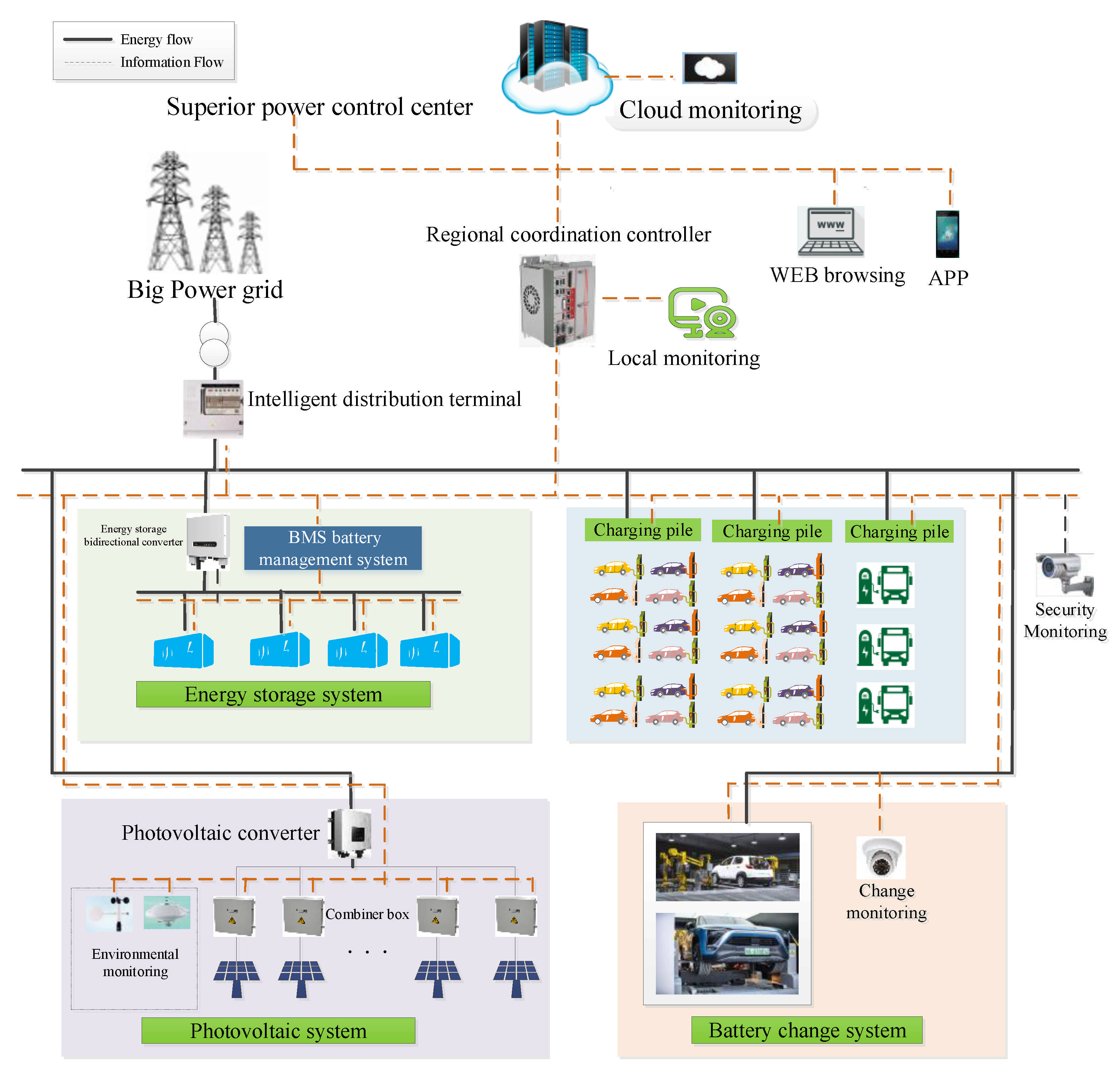
2. “Photovoltaic-Storage-Charging-Change” System Architecture and Control Model Description

2.1. “Photovoltaic-Storage-Charging-Change” System Architecture

The system architecture of an EV “Photovoltaic-Storage-Charging-Change” station discussed in this paper is shown in Figure 1. It mainly includes four parts: the photovoltaic system, the energy storage system, the charging system, and the battery changing system. Detailed information of these parts is given as follows:
(a) Photovoltaic system
The photovoltaic system mainly includes photovoltaic modules, photovoltaic inverters, and other major equipment. The electricity generated by photovoltaics can be transmitted to the energy storage system, charging piles, and the battery changing system, as well as to the main power grid. In this paper, the photovoltaic power generation model only considers the impact of light intensity and ambient temperature, as shown in Formulas (1) and (2) [33].
P p v i = P s t e G i G s t e 1 + k T p t i T s t e i
T p t i = T e t i + 30 × G i 1000
where P p v i —photovoltaic system power generation at time i, kW; P s t e —rated output power of a single photovoltaic panel in a standard test environment, kW; T s t e —rated temperature of a single photovoltaic panel in a standard test environment, °C; G i —light intensity at time i, kW/m2; G s t e —the light intensity under the standard test environment, which is 1 kW/m2; T p t i —photovoltaic system temperature at time i, °C; T e t i —environmental temperature at time i, °C.
(b) Energy storage system
The energy storage system includes devices such as energy storage converters and Lithium iron phosphate battery systems. It is mainly responsible for absorbing photovoltaic power generation as well as providing a backup energy source to satisfy peak energy demands. The energy storage system model, as shown in Formula (3), only considers system states such as current charging and discharging modes, and the residual power of each item of energy storage equipment, while ignoring the internal power electronic control. The limitation of the charging and discharging processes of the lithium iron phosphate battery pack in the energy storage system is that its maximum charging and discharging power cannot exceed its maximum rate.
P d i s i = P d i s c i ω c i η d i s c + P d i s d i ω d i η d i s d
where P d i s i —total charging and discharging power of the energy storage system at the time i, kW; P d i s c i —charging power of the energy storage system at the time i, kW; P d i s d i —discharging power of the energy storage system at the time i, kW; ω c i —charge state of the energy storage system at the time i, if charging, ω c i = 1 ; ω d i —discharge state of the energy storage system at the time i, if discharging, ω d i = 1 .
(c) Charging system
Charging piles in the charging system are used as energy interactions between EVs and the power grid. Under normal conditions, EVs take power from grid through charging piles. When the power grid is short of power, EVs can also be used as an adjustable load to transmit electric energy to the power grid through V2G technology. The remaining electricity and charging demand of EV at any time of the day are represented by Formula (4) [34].
S E V i + 1 = S E V i + λ c p P E V i Δ t P E V , d c p i Δ t
where S E V i + 1 —remaining EV battery power at time i + 1, % ; S E V i —remaining EV battery power at time i, % ; λ c p —charging efficiency of the EV; Δ t —time interval, min; P E V , d c p i —the power consumption of the EV at the time i, kW.
(d) Change system
Battery changing is a supplementary option for EV charging. At present, the shortest charging time by high-power fast charging piles for EVs is about 30 min to 2 h, which is too long for general EV users. However, an automatic battery changing process includes removing the low-power battery from EVs and loading a fully charged one. The whole process only takes 3 to 5 min based on the operation experiences of a pilot station in Shanghai, China. Therefore, battery changing is an important supplementary option for EV users, in addition to charging.
In the battery changing system, there is a certain amount of fully charged batteries in stock to ensure that EV users can exchange fully charged batteries at any time. The low-power batteries replaced from EVs are charged on the battery rack and can be reused for changing after it is fully charged. Therefore, the batteries in the battery changing system can be used as backup energy storage to relieve energy supply tension. The model of the battery changing system is described in Formulas (5)–(8):
P e s i = n = 1 156 P n , e s i λ c e s ω n , e s i
S N , e s i = Q e s 0 P E V , d c p i Δ t
S e s i = N = 0 N E V S N , e s i ,   N = 0 , 1 , 2 , , N E V
S t e s i + 1 = S t e s i + P e s i Δ T S e s i
where P e s i —total charging power of the battery changing system at time i, kW; n —the number of chargers in the battery changing system; P n , e s i —the charging power of the nth charger at time i, kW; λ c e s —the charging efficiency of the charging compartment to the battery to be replaced; ω n , e s i —the state of the nth charger at time i, charging is 1 and discharging is −1, otherwise it is 0; N —the number of EVs that need to be replaced; S N , e s i —the EV’s electric quantity that is replaced at time i; Q e s 0 —initial power; S e s i —total power of the EV that is replaced at time i; S t e s i + 1 —total amount of change electricity required by the EV at time i + 1; S t e s i —total amount of change electricity required by the EV at time i; Δ T —time interval, m i n .

2.2. Control Model of “Photovoltaic-Storage-Charging-Change” Integrated System

The “Photovoltaic-Storage-Charging-Change” integrated system is a comprehensive green/flexible EV energy supply system that integrates the photovoltaic subsystem, the energy storage subsystem, the charging subsystem, and the battery changing subsystem. The 24 h daily control objective of this integrated system is to meet the EVs’ energy demands by coordinating different subsystems at the lowest cost. The control model of the “Photovoltaic-Storage-Charging-Change” integrated system includes regular operation constraints, carbon emissions constraints, as well as the optimization objective function.
A. Regular operation constraints
In the operation of the “Photovoltaic-Storage-Charging-Change” integrated system, the internal constraints of each subsystem need to be met.
(a) Photovoltaic output constraints:
P p v , m i n P p v i P p v , m a x
(b) Energy storage system constraints [35]:
20 % S d i s , m a x S d i s i 90 % S d i s , m a x
S d i s i + 1 = S d i s i η d i s P d i s i S d i s , m a x
0 P d i s c i γ d i s c S d i s s γ d i s c S d i s s P d i s d i 0
(c) Charging system constraints [36]:
S E V , m i n S E V i S E V , m a x
Δ P E V i = 1 λ c p α E V P E V i 1
η m i n P E V i P E V i η m a x P E V i
i = 1 T P E V i = i = 1 T P E V i
(d) Changing system constraints:
η c e s , m i n P e s , m a x λ c e s P n , e s i Δ T η c e s , m a x P e s , m a x
where P p v i —the power generation of the photovoltaic system at the time i, kW; P d i s d i —the discharge power of the energy storage system at the time i, kW;   P d i s c t —charging power of the energy storage system at the time i, kW; η d i s c —charge efficiency of the energy storage system; η d i s d —discharge efficiency of the energy storage system; S d i s i —capacity of the energy storage system at the time i, kWh; S d i s , m a x —maximum capacity of the energy storage system, kWh; S d i s s —rated capacity of the lithium iron phosphate battery pack of the energy storage system, kWh; γ d i s c —maximum allowable charge rate of the lithium iron phosphate battery pack of the energy storage system; γ d i s d —maximum discharge rate of the lithium iron phosphate battery pack of the energy storage system;   S E V , m i n —the lower limit of battery storage energy, % ; S E V , m a x —the upper limit of battery storage energy, % ; α E V —power adjustment coefficient; η m i n —minimum charging margin in disordered charging mode; η m a x —maximum charging margin in disordered charging mode; P E V i —power value of orderly charging of EVs at the time i, kW; P E V i —power value of disorderly charging of EVs at the time i, kW.   η c e s , m i n —the minimum margin for replaced battery in the charging compartment of the battery changing system; P e s , m a x —maximum charging power of the charging compartment, kW; η c e s , m a x —the maximum margin for replaced battery in the charging compartment of the battery changing system.
B. Carbon transaction costs and carbon emission constrains
In the operation of the “Photovoltaic-Storage-Charging-Change” integrated system, carbon transaction costs are especially considered in this paper as shown in Formula (18) [37].
C e i = σ i Q e t Q q t
where   C e i is the carbon transaction cost, σ i is the carbon transaction price of the sub system at time i, Q i e t is subsystem carbon emissions at time i, Q i q t   is subsystem’s carbon emission allowance at time i.
On the basis of Formulas (9)–(17), the maximum carbon emission quota constraints of the “Photovoltaic-Storage-Charging-Change” integrated system are considered in this paper, as shown in Formulas (19) and (20) [38]:
C C O 2 = t i t j P G γ C O 2 π C O 2
C C O 2 C m a x
where γ C O 2 , π C O 2 are the average proportion of carbon-containing power sources in the distribution network and the carbon emission coefficient per kWh.
C. Optimization objective function
The optimization objective function considers energy costs, carbon transaction costs, and the net balance of energy supply and demand, as shown in Formulas (21)–(24):
m i n F = λ 1 F 1 + λ 2 F 2
F 1 = t i t j C n P n , i P R E S i + C w P n , i + C e x c i t i + C d c i + C e i
F 2 = 1 T t i t j P R E S i 2
P R E S i = P G i + μ p v P p v i N p v + μ d i s d P d i s d i N d i s μ c p P c p i N c p P l o a d i E l o a d i μ d i s c P d i s c i N d i s μ e s P e s i N e s
where P R E S i —net power of the integrated system of “Photovoltaic-Storage-Charging-Change” at the time i, kW; P G i —power provided by the distribution network to the system at time i, kW; μ p v —transmission efficiency of photovoltaic system, %; μ d i s d —the discharge efficiency of the storage system, %; μ c p —the transmission efficiency of the charging system, %; P c p i —the power generated by the charging system at the time i, kW; N p v —the number of power generation units in the photovoltaic system; N d i s d —the number of energy storage units in the energy storage system; N c p —the number of AC/DC charging piles in the charging system; N e s —the number of batteries in the battery changing compartment; μ d i s c —charging efficiency of the energy storage system, %; μ e s —charging efficiency of the battery in the battery exchange system,   % ; P e s i —the charging power of the battery at the time i, kW; P l o a d i —total load in the integrated urban “Photovoltaic-Storage-Charging-Change” system at the time i, kW; E l o a d i —the conventional power load of the charging pile in the integration of urban “Photovoltaic-Storage-Charging-Change” at the time i, kW; C n P n , i —the power generation cost of the nth type of power generation unit; C w P n , i —the maintenance cost of the nth type of power generation unit; C e x c i t i —the cost for motivating users to participate in the dispatch; C d c i —the cost for the power station to purchase electricity from the grid; λ 1 , λ 2 —the weighting factors, λ 1 + λ 2 = 1 .
In order to overcome the possible error of subjective experience in weighting, the entropy weight method is applied to the weight in this paper. For a detailed description of the entropy weight method, please refer to the literature [39].

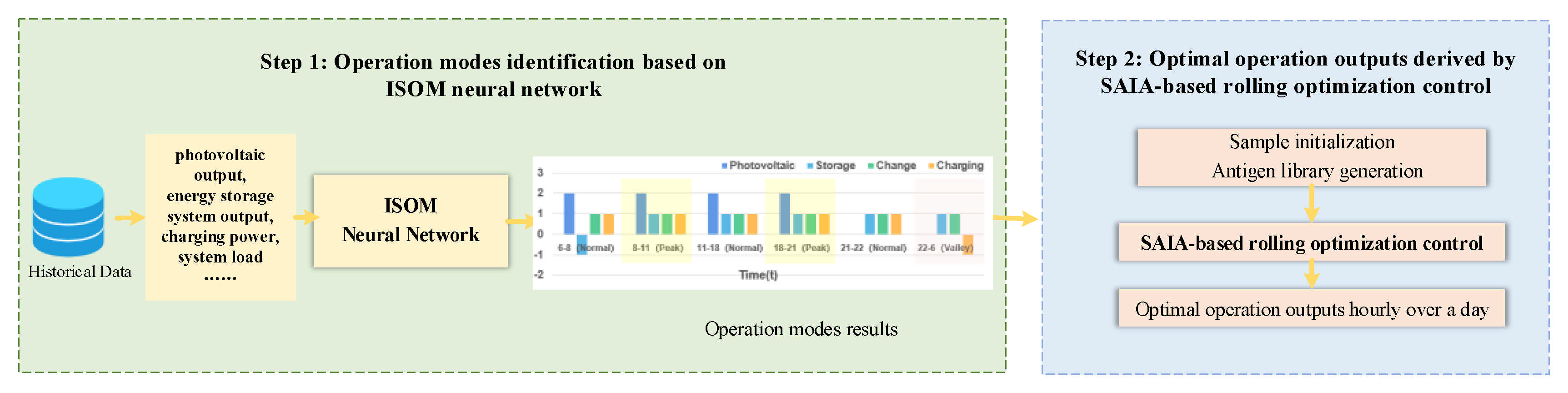
3. Two-Step Intelligent Control of “Photovoltaic-Storage-Charging-Change” System Based on ISOM-SAIA

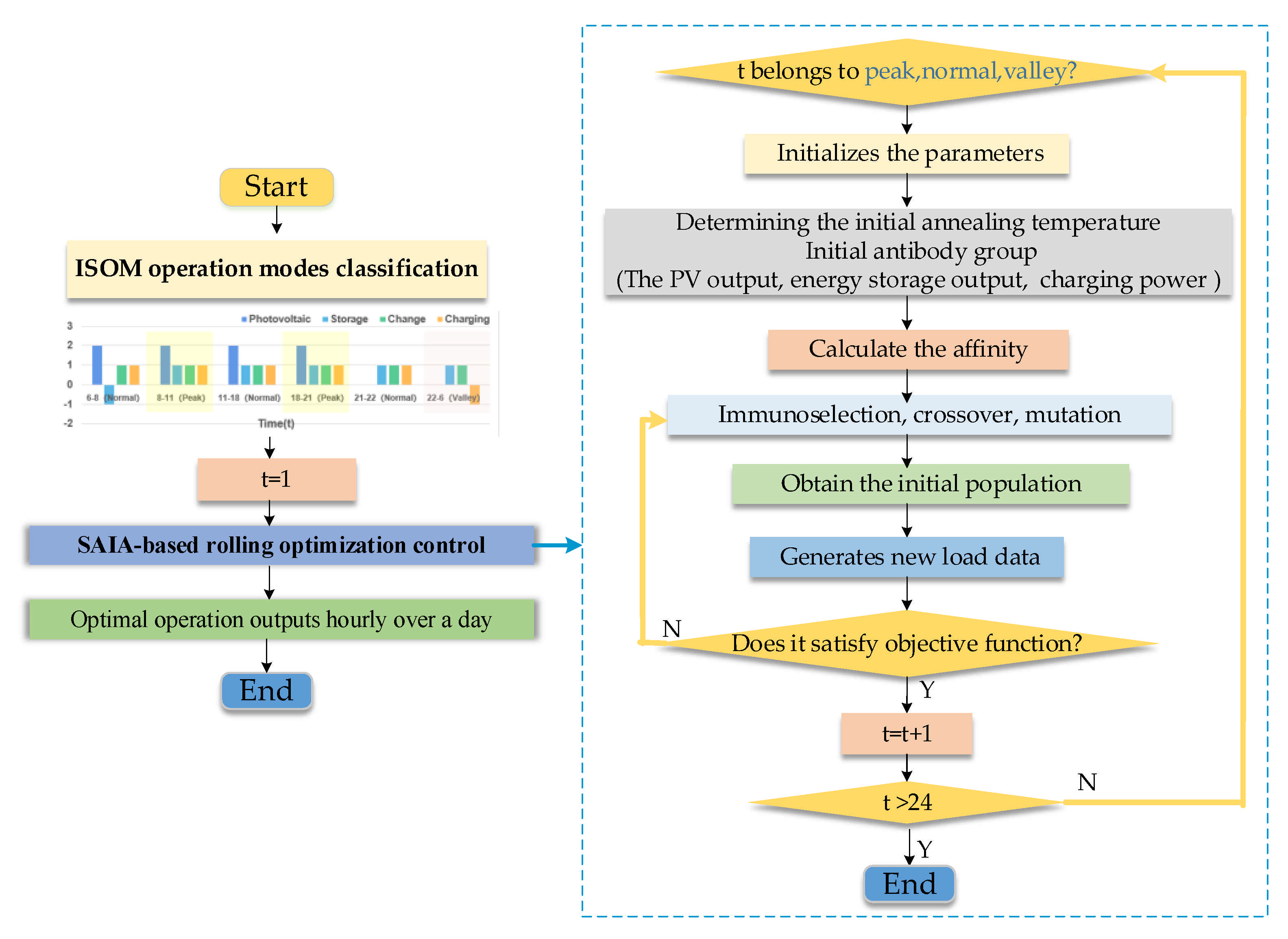
3.1. Overall Architecture of Two-Step Intelligent Control ISOM-SAIA

The overall architecture of two-step intelligent control (ISOM-SAIA) for the integrated EV “Photovoltaic-Storage-Charging-Change” system is shown in Figure 2. The tasks of the two-step intelligent control are to classify the operation modes of all subsystems for each hour using a data-driven intelligent classification method known as the improved self-organizing mapping neural network (ISOM) in the first step, and then calculate the optimal operation outputs of all subsystems for each hour over a day using a rolling optimization method, called simulated annealing immune control (SAIA), in the second step.

3.2. Step 1: Classification of Operation Modes Based on ISOM

The first step of the two-step intelligent control for the integrated EV “Photovoltaic-Storage-Charging-Change” system is to classify the operation modes of all subsystems in each hour of a day based on a data-driven intelligent clustering method known as the improved self-organizing map neural network (ISOM). The ISOM neural network consists of three layers: the input layer, the competition layer and the output layer. The nodes in all layers are connected by weights: ω i j i = 1 , , n ; j = 1 , , m . The input data of ISOM neural network include the system time, EV charging quantity, energy storage SOC, and changed battery SOC, etc. The outputs of the ISOM neural network are the matching operation modes (charging, discharging, optional, not working) of all subsystems in three special time periods of the day (peak periods, flat periods, valley periods). As shown in Figure 3, the ISOM neural network classification procedure is given as follows:
(a) Perform normalized clustering processing on input data sample x i = x 1 , x 2 , , x n . The state variables, represented by x i , are the system time, EV charging quantity, energy storage system, battery SOC, etc.;
(b) Initialize the connection weights of ISOM neural network and locate it in the middle area of the input data, set the time count t = 0, determine the learning rate, and the learning radius r;
(c) Calculate the Euclidean distance between the input sample processed in step (a) and the neurons in the competition layer according to Equation (25);
d j = i = 1 n ( x i k ω i j ) 2
(d) Select the neuron of the competition layer with the smallest Euclidean distance as the winning neuron to replace the original neuron;
(e) Adjust the weights between the input layer and the competition layer, and the weights between the competition layer and output layer according to Equations (26) and (27);
ω i j = ω i j + ξ 1 x i ω i j
ω j k = ω j k + ξ 2 y k ω j k
where y k is the category of different control modes (k = 1, 2, 3, …).
(f) If there are still input data samples, then t = t + 1, and return to step (c), otherwise go to (g).
(g) Output the matching operation modes (power output, power input, optional, and not working) of all subsystems in three special time periods of the day (peak periods, flat periods, valley periods).

3.3. Step 2: SAIA-Based Rolling Optimization Control

The second step of the two-step intelligent control for the integrated EV “Photovoltaic-Storage-Charging-Change” system is to derive the optimal operation outputs of all subsystems in each hour of a day with a rolling optimization process based on a simulated annealing immune algorithm (SAIA) combined with a simulated annealing (SA) and immune algorithm (IA). Figure 4 shows the flow chart of SAIA-based rolling optimization control procedure, which has three main procedures—(a), (b) and (c)—as follows.
(a)
Based on the classification results from Step 1 in Section 3.2, the operation modes of four subsystems in each time period of peak, flat, and valley are obtained.
(b)
Starting from t = 1, check which special time period t belongs to, and derive the optimal operation output of all subsystems using the SAIA algorithm based on the objective function and constraints given in Formulas (9)–(24). The SAIA optimization calculation process is given from (1) to (8) as follows:
(1) Let the total population be N , the number of memory cell antibodies be N m , the crossover probability be P c , the mutation probability be   P m , the temperature cooling coefficient be   C , the number of memory cells be g, and the initial annealing temperature be   T ;
(2) The system time, EV energy supply loads, and system operating status are used as antigens to initialize the parameters;
(3) Randomly generate N N m antibodies, mainly using photovoltaics, energy storage, charging piles, etc. as the initial antibody group objects, and form the initial population together with   N m antibodies in the memory unit; if the memory unit is empty, randomly generate   N antibodies to form the initial population, make   k = 0 ;
(4) Calculate the actual load value of each antibody P i (photovoltaic system output, energy storage system output, electric vehicle charging power, rechargeable battery charging power, etc.), according to Formulas (3) and (4) to determine the current temperature of the system operation requirements and control output Affinity   TF P i between each other, save   N m antibodies in the memory unit P g ;
TF P i = e f P i f P g / t i = 1 N e f P i f P g / t
(5) Implement the immune selection, crossover, and mutation operations to determine the type of control strategy;
(6) Perform the simulated annealing operation of fixed-step sampling on the parameters of energy equipment, such as the photovoltaic, energy storage, charging and swapping parameters, in the population, and new antibodies are generated. If the result satisfies Formulas (3)–(5), it is updated and the new load value is calculated; Otherwise, it remains unchanged;
min [ 1 , exp ( Δ / T k ) random 0 , 1 ]
where T k —annealing temperature in k.
(7) Determine whether the algorithm convergence criterion is satisfied. If it is satisfied, perform the de-temperature operation, output the control strategy result, and end the algorithm; otherwise, return to step (5);
(8) Let k = k + 1 , input the Formulas (3)–(6) to the de-temperature operation.
T k = C g T k 1 , C 0 , 1
(c)
If t < 24 h, t = t + 1; otherwise, the algorithm ends and derives the optimal operation modes of all subsystems in each hour of a day.

4. Simulation Analysis

4.1. Data Source and System Parameters of “Photovoltaic-Storage-Charging-Change” System

The data source of the simulation analysis in this section comes from a demonstration project of an EV “Photovoltaic-Storage-Charging-Change” station in Shanghai, China. It is equipped with four subsystems: photovoltaic, energy storage, charging, and battery changing. In addition, it provides both fast charging and battery changing services for EVs. The installed capacity, power generation costs, and maintenance costs of each subsystem are shown in Table 1.
The typical daily EV charging and battery changing load curves of the green/flexible EV energy supply station in summer and winter are shown in Figure 5.

4.2. Tests for Two-Step Intelligent Control of “Photovoltaic-Storage-Charging-Change” System

4.2.1. Tests for Step 1: Classification of Daily Operation Modes Based on ISOM Neural Network

In this section, the EVs’ daily energy demands and the system parameters of the EVs’ “Photovoltaic-Storage-Charging-Change” system, as shown in Section 4.1, are used in the tests of the first step of two-step intelligent control method proposed in this paper. Each subsystem of the EVs’ “Photovoltaic-Storage-Charging-Change” system has four operation modes. They are, respectively, the power output state (indicated by 2), the power input state (indicated by −1), the power output or input state (indicated by 1), and the not-working state (indicated by 0).
Based on the method for the classification of ISOM-based operation modes given in Section 3.2, the hourly operation modes of all subsystems in the “Photovoltaic-Storage-Charging-Change” system are derived and shown in Figure 6. From Figure 6, the operation modes of all subsystem during different time periods are basically clear: the photovoltaic subsystem can only output electric power during the daytime; the energy storage system can output power to relieve the high EV energy demand during some peak periods, and can input power during normal and valley periods; the battery changing subsystem is optional for power output or input during the entirety of the day; the charging subsystem is optimal for power output or input during most hours of the day, and can only input power during several normal and valley periods.

4.2.2. Tests for Step 2: Optimal Daily Operation Outputs by SAIA-Based Rolling Optimization

In this section, the second step of the two-step intelligent control method proposed in Section 3.3 of this paper is tested based on the operation mode classification result derived from Section 4.2.1.
The optimal operation outputs of each subsystem and the total power of the integrated system purchased from grid for all hours of a typical summer day and a typical winter day are derived via the SAIA-based rolling optimization control method, and are shown in Figure 7. In order to test the performance of the proposed two-step intelligent control method in terms of the peak shaving and valley filling of a power grid, as well as energy costs and carbon emission reduction, the following simulation analysis is carried out.
A.
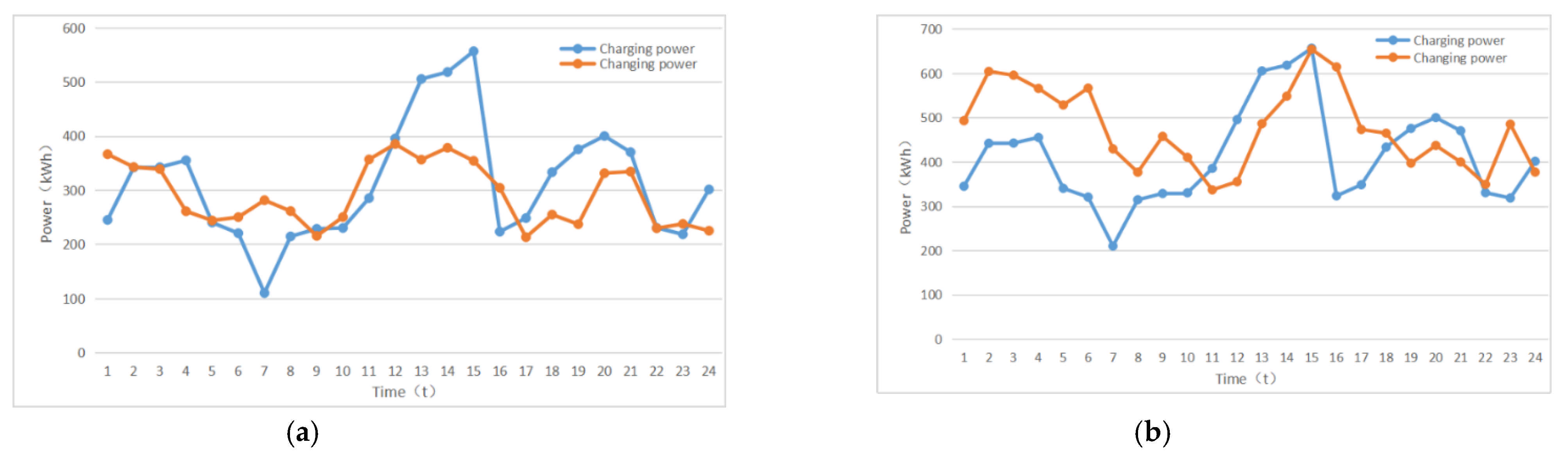
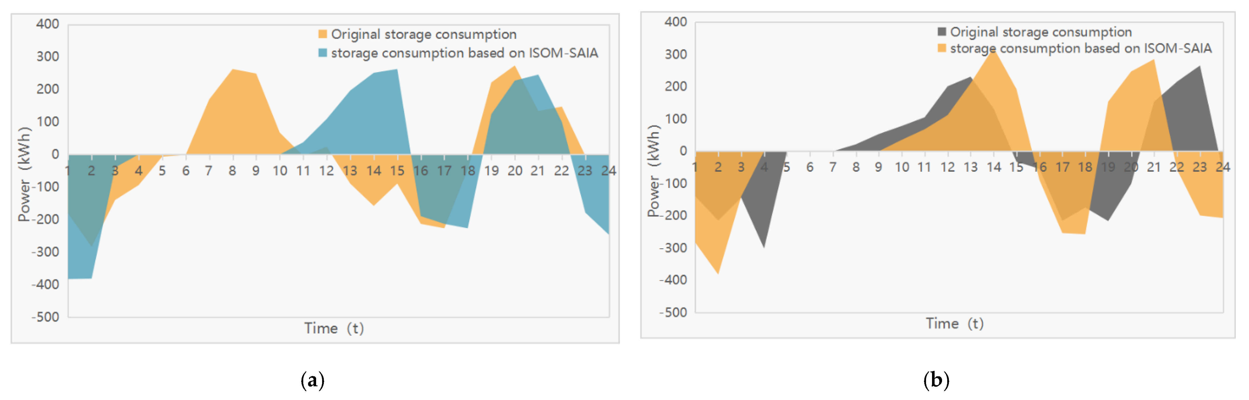
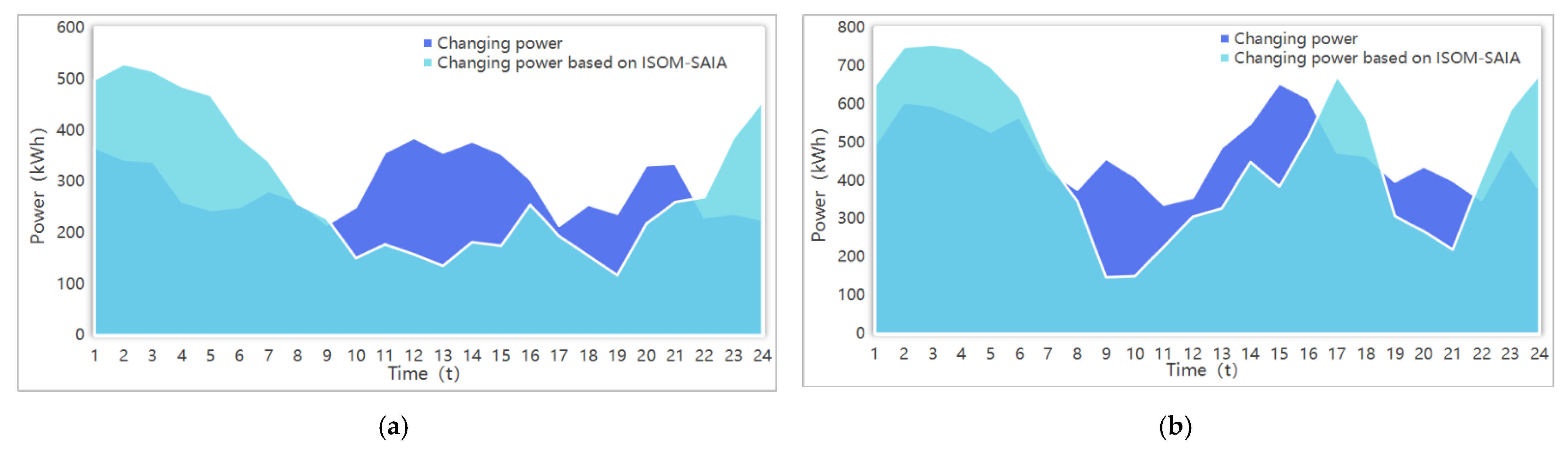
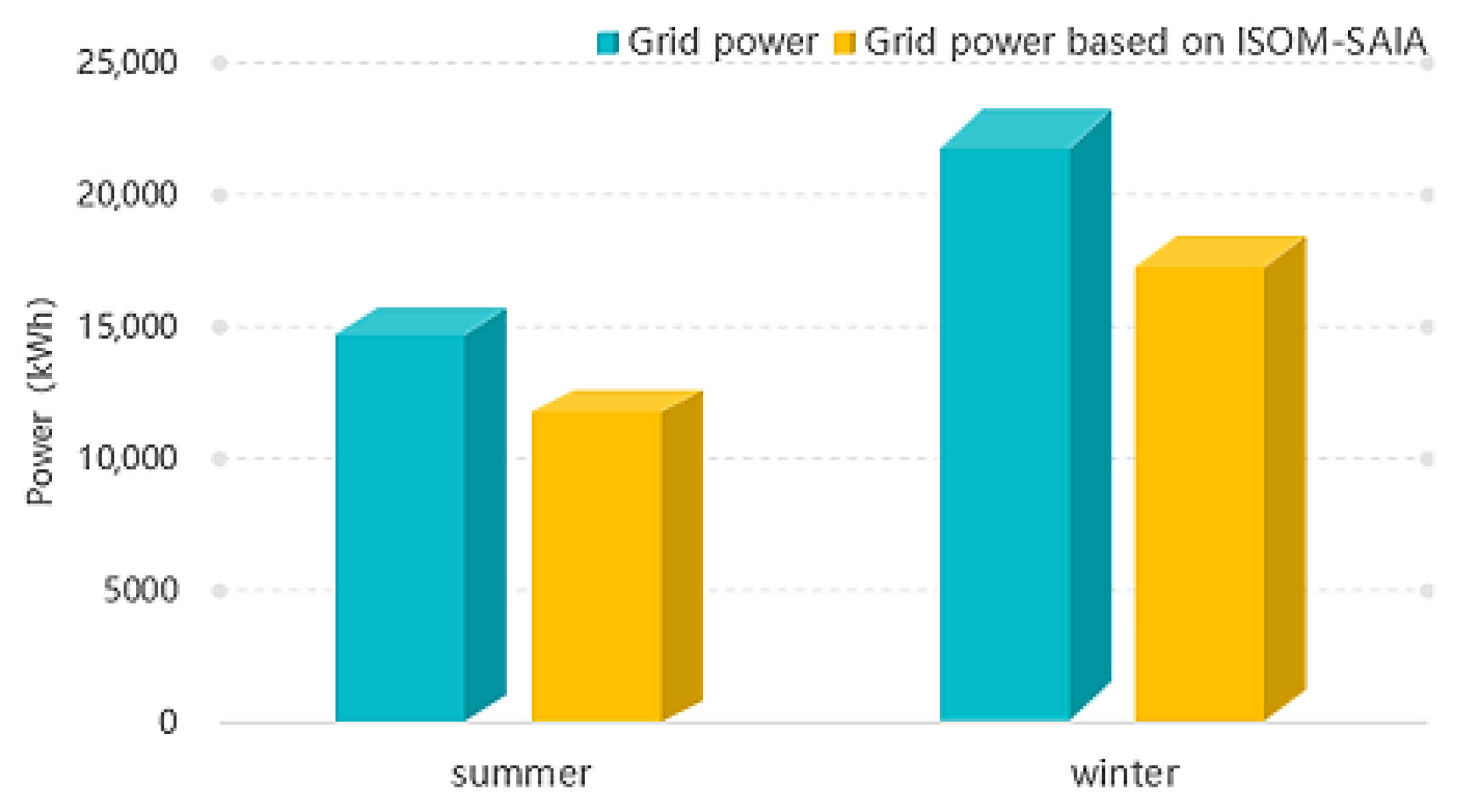
Simulation analysis of power grid peak shaving and valley filling performance
In Figure 8 and Figure 9, the operation outputs of the battery changing subsystem and the energy storage subsystem derived by the proposed two-step intelligent control ISOM-SAIA are compared with original operation records. Both subsystems contribute to the peak shaving and valley filling of the grid. Figure 10 provides more detailed statistics on the performance of peak shaving and valley filling of power grid: the peak load reduction can reach 2387.57 kWh and the valley filling is 2132.68 kWh on a typical day in summer; the peak load reduction can reach 1663.18 kWh and the valley filling 2346.73 kWh on a typical day in winter.
B.
Simulation analysis of carbon transaction costs and carbon emission constraints
In order to test the performance of the carbon transaction cost and carbon emission constraints (Formulas (18)–(20)) considered in the proposed ISOM-SAIA two-step intelligent control method, Figure 11 compares the power purchased from power grid of the EV “Photovoltaic-Storage-Charging-Change” station on a typical day with and without carbon constraints. It indicates that after considering the carbon transaction costs and carbon emission constraints, the total electricity purchased by the EV energy supply station from the grid is reduced from the original 15,738.32 kWh to 12,629.64 kWh on a typical summer day, and it drops from 23,215.62 kWh to 18,428.3 kWh on a typical winter day, while meeting the same daily EV energy demand. It can save 17,634.68 yuan on a typical summer day, and 10,453.82 yuan on a typical winter day.
Due to the high proportion of fossil-fuel fired power generation in the power grid, the carbon emissions per kilowatt hour of power purchased from grid are higher than those of photovoltaic power generation in the EV energy supply station. Therefore, when meeting the same EV energy demand, reducing the proportion of the grid-source power in the EV energy supply station can reduce both the energy costs and carbon emissions. Therefore, the carbon transaction costs and carbon emission constraints considered in the proposed two-step intelligent control method can help to achieve both economic and environmental benefits.
In addition, to further study the sensitivity of the maximum carbon emission limit, the overall operation benefits of the EV “Photovoltaic-Storage-Charging-Change” station, under different carbon emission limits, are analyzed and shown in Figure 12. It indicates that different carbon emission limits can have a significant effect on the benefits of the system. Therefore, it is necessary to select an appropriate carbon emission limit when implementing the proposed two-step intelligent control ISOM-SAIA for the EV “Photovoltaic-Storage-Charging-Change” station to ensure both high environmental and economic benefits.

5. Conclusions

A two-step intelligent control method, ISOM-SAIA, is proposed in this paper to solve the problem of the 24 h control and regulation of a green/flexible EV energy supply station including four subsystems such as a photovoltaic subsystem, an energy storage subsystem, an EV charging subsystem, and an EV battery changing subsystem, under China’s Dual Carbon Target. The innovations and contributions of this paper are listed as follows:
(1) The two-step intelligent control method, ISOM-SAIA, proposed in this paper effectively reduces the computation burden of solving the multi-dimensional mixed-integer programming problem of the simultaneous optimization of 24 h operation modes and outputs of four subsystems in the green/flexible EV energy supply station into two steps: step 1 for the data-driven classification of operation modes, and step 2 for the rolling optimization of operation outputs.
(2) Proper carbon transaction costs and carbon emission constraints are considered in the proposed control method, and the simulation results indicate that the added carbon transaction costs and carbon emission constraints can help to save costs and reduce carbon emissions for the green/flexible EV energy supply station.
In conclusion, the two-step intelligent control method, ISOM-SAIA, proposed in this paper is a useful control method for the 24 h control and regulation of integrated green/flexible EV energy supply stations. It can help the stations to optimally allocate energy flows between four subsystems, effectively respond to the peak shaving and valley filling of the power grid, save energy costs, and reduce carbon emissions.

Author Contributions

Conceptualization, S.S. and C.F.; Methodology, C.F., H.W. and H.Z.; Resources, S.S., D.P. and H.Z.; Software, C.F., H.W. and Y.L.; Validation, C.F., J.L., Y.L. and D.P.; Writing—original draft, S.S., J.L. and H.Z.; Writing—review and editing, S.S. and H.Z. All authors have read and agreed to the published version of the manuscript.

Funding

This work is supported by the Science and Technology Project of the State Grid Corporation of China (No. 52094019007G), and the Shanghai Rising-Star Program (No. 20QB1400300).

Institutional Review Board Statement

Not applicable.

Informed Consent Statement

Not applicable.

Conflicts of Interest

The authors declare no conflict of interest.

References

  1. IEA. Global EV Outlook 2021; IEA: Paris, France, 2021; Available online: https://www.iea.org/reports/global-ev-outlook-2021 (accessed on 31 July 2021).
  2. Xu, L.; Zhang, J.; Bao, Z.; Cao, Y. A comparative study between IPSO and MIP for co-ordinated scheduling of electricity and heat within a microgrid. Trans. Inst. Meas. Control 2013, 35, 444–456. [Google Scholar] [CrossRef]
  3. Yang, T.; Zhao, L.; Wang, C. Review on application of artificial intelligence in power system and integrated energy system. Autom. Electr. Power Syst. 2019, 43, 2–14. [Google Scholar]
  4. Jha, M.; Blaabjerg, F.; Khan, M.A.; Bharath Kurukuru, V.S.; Haque, A. Intelligent Control of Converter for Electric Vehicles Charging Station. Energies 2019, 12, 2334. [Google Scholar] [CrossRef] [Green Version]
  5. Beigvand, S.D.; Abdi, H.; La Scala, M. Combined heat and power economic dispatch problem using gravitational search algorithm. Electr. Power Syst. Res. 2016, 33, 160–172. [Google Scholar] [CrossRef]
  6. Jiang, X.; Jing, Z.; Li, Y.; Wu, Q.; Tang, W. Modelling and operation optimization of an integrated energy based direct district water-heating system. Energy 2014, 64, 375–388. [Google Scholar] [CrossRef]
  7. Meng, A.; Mei, P.; Lu, H. Crisscross optimization algorithm for combined heat and power economic dispatch. Power Syst. Prot. Control 2016, 44, 90–97. [Google Scholar]
  8. Ndiaye, E.H.M.; Ndiaye, A.; Faye, M.; Gueye, S. Intelligent Control of a Photovoltaic Generator for Charging and Discharging Battery Using Adaptive Neuro-Fuzzy Inference System. Int. J. Photoenergy 2020, 2020, 8649868. [Google Scholar] [CrossRef]
  9. Qu, K.; Zhang, X.; Yu, T.; Han, C.J. Knowledge transfer based Q-learning algorithm for optimal dispatch of multi-energy system. Autom. Electr. Power Syst. 2017, 41, 18–25. [Google Scholar]
  10. Liu, X. Heterogeneous Multi-Agent Cooperative Control and Its Application in DC Microgrid; Huazhong University of Science and Technology: Wuhan, China, 2019. [Google Scholar]
  11. Meng, Y.; Cao, Y.; Zeng, J. Design and Implementation of Intelligent Management System for Electric Vehicle Charging Station. Instrum. Technol. 2016, 33, 22–24. [Google Scholar]
  12. Zhang, Y.; Luo, H.; Wang, Y. Research on Hybrid Energy Storage Power Distribution and Bus Voltage Stabilization of Photovoltaic DC Microgrid Based on Fuzzy-Sag Control. Electr. Meas. Instrum. 2020, 1–9. Available online: http://kns.cnki.net/kcms/detail/23.1202.TH.20200806.1637.014.html (accessed on 26 March 2021).
  13. Qu, F.; Zhao, J.; Cai, Z.; Hu, C.; Dai, S.; Sun, Q. Cooperative optimization control strategy of electric vehicle and temperature-controlled load virtual power plant. J. Electr. Power Syst. Autom. 2021, 33, 48–56. [Google Scholar]
  14. Tang, M.; Qu, X.; Yao, R.; Zhang, Y.; Chen, W.; Jia, K. Multi-photovoltaic Coordinated Control Strategy in DC Distribution Network Based on Discrete Consensus Algorithm. Autom. Electr. Power Syst. 2020, 44, 89–95. [Google Scholar]
  15. Blasius, E.; Federau, E.; Janik, P.; Leonowicz, Z. Heuristic Storage System Sizing for Optimal Operation of Electric Vehicles Powered by Photovoltaic Charging Station. Int. J. Photoenergy 2016, 2016, 3980284. [Google Scholar] [CrossRef] [Green Version]
  16. Zhang, X.; Li, L.; Fu, Y. Stability Analysis and Regional Cooperative Control of Controllable Inertia Optical Storage Interconnection System. High Volt. Technol. 2021, 47, 1694–1705. [Google Scholar]
  17. Jiang, Y. Simulation of electric vehicle charging load cooperative control based on microgrid. Comput. Simul. 2020, 37, 87–90. [Google Scholar]
  18. Ramadhani, U.H.; Shepero, M.; Munkhammar, J.; Widén, J.; Etherden, N. Review of probabilistic load flow approaches for power distribution systems with photovoltaic generation and electric vehicle charging. Int. J. Electr. Power Energy Syst. 2020, 120, 106003. [Google Scholar] [CrossRef]
  19. Shimazu, T.; Takahashi, A.; Shimofuji, K.; Funabiki, S.; Nagata, T. Reactive power control of power conditioning systems to avoid voltage deviation in high-voltage distribution systems caused by both of photovoltaic generation and electric vehicle charging. Electr. Eng. Jpn. 2018, 138, 416–422. [Google Scholar]
  20. Meng, C.; Jiang, Y.; Dai, J. Study on the scheduled performance control of a class of nonlinear multi-agent systems. J. Nanchang Hangkong Univ. 2019, 33, 1–6. [Google Scholar]
  21. Xu, S.; Yan, Z.; Feng, D.; Zhang, L. Electric vehicle charging collaborative control strategy based on multi-agent. Electr. Power Autom. Equip. 2014, 34, 7–13. [Google Scholar]
  22. Hao, R.; Ai, Q.; Zhu, Y. Energy Internet collaborative optimization control based on multi-agent consistency. Autom. Electr. Power Syst. 2017, 41, 10–17. [Google Scholar]
  23. Zhou, Y.; Wang, K.; Li, G.; Han, B.; Liu, Z. Distributed hierarchical control strategy of microgrid based on multi-agent consensus algorithm. Autom. Electr. Power Syst. 2017, 41, 142–149. [Google Scholar]
  24. Mesbahi, T.; Bartholomeüs, P.; Rizoug, N.; Sadoun, R.; Khenfri, F.; Le Moigne, P. Advanced Model of Hybrid Energy Storage System Integrating Lithium-Ion Battery and Supercapacitor for Electric Vehicle Applications. IEEE Trans. Ind. Electron. 2021, 68, 3962–3972. [Google Scholar] [CrossRef]
  25. Shin, M.; Choi, D.; Kim, J. Cooperative Management for PV/ESS-Enabled Electric Vehicle Charging Stations: A Multiagent Deep Reinforcement Learning Approach. IEEE Trans. Ind. Inform. 2020, 16, 3493–3503. [Google Scholar] [CrossRef]
  26. Vavilapalli, S.; Padmanaban, S.; Subramaniam, U.; Mihet-Popa, L. Power Balancing Control for Grid Energy Storage System in Photovoltaic Applications-Real Time Digital Simulation Implementation. Energies 2017, 10, 928. [Google Scholar] [CrossRef] [Green Version]
  27. Kohonen, T. Self-organized formation of topologically correct feature maps. Biol. Cybern. 1982, 43, 59–69. [Google Scholar] [CrossRef]
  28. Musharavati, F.; Hamouda, A.S.M. Enhanced simulated-annealing-based algorithms and their applications to process planning in reconfigurable manufacturing systems. Adv. Eng. Softw. 2012, 45, 80–90. [Google Scholar] [CrossRef]
  29. Trung, N.T.; Anh, D.T. Comparing Three Improved Variants of Simulated Annealing for Optimizing Dorm Room Assignments. In Proceedings of the IEEE-RIVF International Conference on Computing and Communication Technologies, Danang, Vietnam, 13–17 July 2009. [Google Scholar]
  30. Zhang, Y.; Liu, C. An Improved Evolution Algorithm of Immune Detectors for Network Data Analysis. In Proceedings of the International Conference on Intelligent Computing and Human-Computer Interaction (ICHCI), Sanya, China, 4–6 December 2020. [Google Scholar]
  31. Jiang, J.; Song, C.; Ping, H.; Zhang, C. Convergence Analysis of Self-adaptive Immune Particle Swarm Optimization Algorithm. In Proceedings of the 15th International Symposium on Neural Networks (ISNN), Minsk, Belarus, 25–28 June 2018. [Google Scholar]
  32. Shi, J.; Su, Y.D.; Xie, M. Research on Application of IGA (Immune Genetic Algorithm) to the Solution of Course-Timetabling Problem. In Proceedings of the 4th International Conference on Computer Science and Education, Nanning, China, 25–28 July 2009. [Google Scholar]
  33. Yang, Y. Research on Control Strategy of Power Electronic Transformer with Access of Photovoltaic-Storage System and Charging Station; North China Electric Power University: Beijing, China, 2020. [Google Scholar]
  34. Ni, C.; Liu, X. Battery Capacity Optimal Configuration and Economical Analysis of Energy Storage Photovoltaic System. Zhejiang Electr. Power 2019, 38, 1–10. [Google Scholar]
  35. Chen, T.; Xu, X.; Yan, Z.; Zhu, Y. Optimal operation based on deep reinforcement learning for energy storage system in photovoltaic-storage charging station. Electric Power Autom. Equip. 2021, 41, 1–9. [Google Scholar]
  36. Shang, Z.; Wang, G. Research on Day-ahead Optimal Economic Dispatching Strategy for Micro-energy-grid and Analysis of Electric Energy Storage Strategy. Electr. Power Sci. Eng. 2020, 36, 9–16. [Google Scholar]
  37. Tang, W.; Zhang, Y.; Xuan, D.; Jiang, D. Low-carbon Park Economic Operation Scheduling Strategy Taking into Account the Tiered Carbon Trading Mechanism. Distrib. Util. 2021, 38, 10–18. [Google Scholar]
  38. Mei, G.; Gong, J.; Zhang, Y. Scheduling Strategy for Multi-energy Complementary Virtual Power Plant Considering the Correlation Between Wind and Solar Output and Carbon Emission Quota. Proc. CSU-EPSA 2021, 33, 62–69. [Google Scholar]
  39. Hananeh, F.; Alireza, Z.; Shahram, J. The role of demand response in single and multi-objective wind-thermal generation scheduling: A stochastic programming. Energy 2014, 64, 853–867. [Google Scholar]
Figure 1. “Photovoltaic-Storage-Charging-Change” integrated system architecture.
Processes 09 01918 g001
Figure 2. Overall architecture of two-step intelligent control based on ISOM-SAIA.
Processes 09 01918 g002
Figure 3. ISOM-based operation mode classification process.
Processes 09 01918 g003
Figure 4. SAIA-based rolling optimization control procedure.
Processes 09 01918 g004
Figure 5. (a) EV energy demand curve of charging and battery changing on a typical day in summer; (b) EV energy demand curve of charging and battery changing on a typical day in winter.
Processes 09 01918 g005
Figure 6. Daily operation mode classification results based on ISOM neural network: (a) in summer; (b) in winter.
Processes 09 01918 g006
Figure 7. Results of coordinated regulation of various systems on a typical day: (a) in summer; (b) in winter.
Processes 09 01918 g007
Figure 8. Comparison of power outputs of energy storage subsystem on a typical day: (a) in summer; (b) in winter.
Processes 09 01918 g008
Figure 9. Comparison of power consumption of battery changing subsystem on a typical day: (a) in summer; (b) in winter.
Processes 09 01918 g009
Figure 10. Comparison of the results of peak shaving and valley filling: (a) in summer; (b) in winter.
Processes 09 01918 g010
Figure 11. Power purchased from grid on a typical day.
Processes 09 01918 g011
Figure 12. System benefits under different maximum carbon emission limits.
Processes 09 01918 g012
Table 1. Parameters of each power generation unit.
TypeInstalled Capacity
(kWh)
Power Generation Cost
(Yuan kWh)
Maintenance Cost
(Yuan kWh)
Photovoltaic100.410.0401
Energy Storage10000.680.0843
Charging System40000.560.0512
Battery Changing System23400.680.0753
Publisher’s Note: MDPI stays neutral with regard to jurisdictional claims in published maps and institutional affiliations.

