
A Study on the Mechanical Properties of Unbolted and Bolted Composite Rock Masses Under the Influence of Different Grain Sizes

Abstract
1. Introduction
2. Preparation and Testing Protocol for Composite Rock Specimens
2.1. Preparation of Composite Rock Specimens
2.2. Test Platform and Test Process
3. Analysis of Test Results of Composite Rock Mass
3.1. Mechanical Properties of Composite Rock Mass
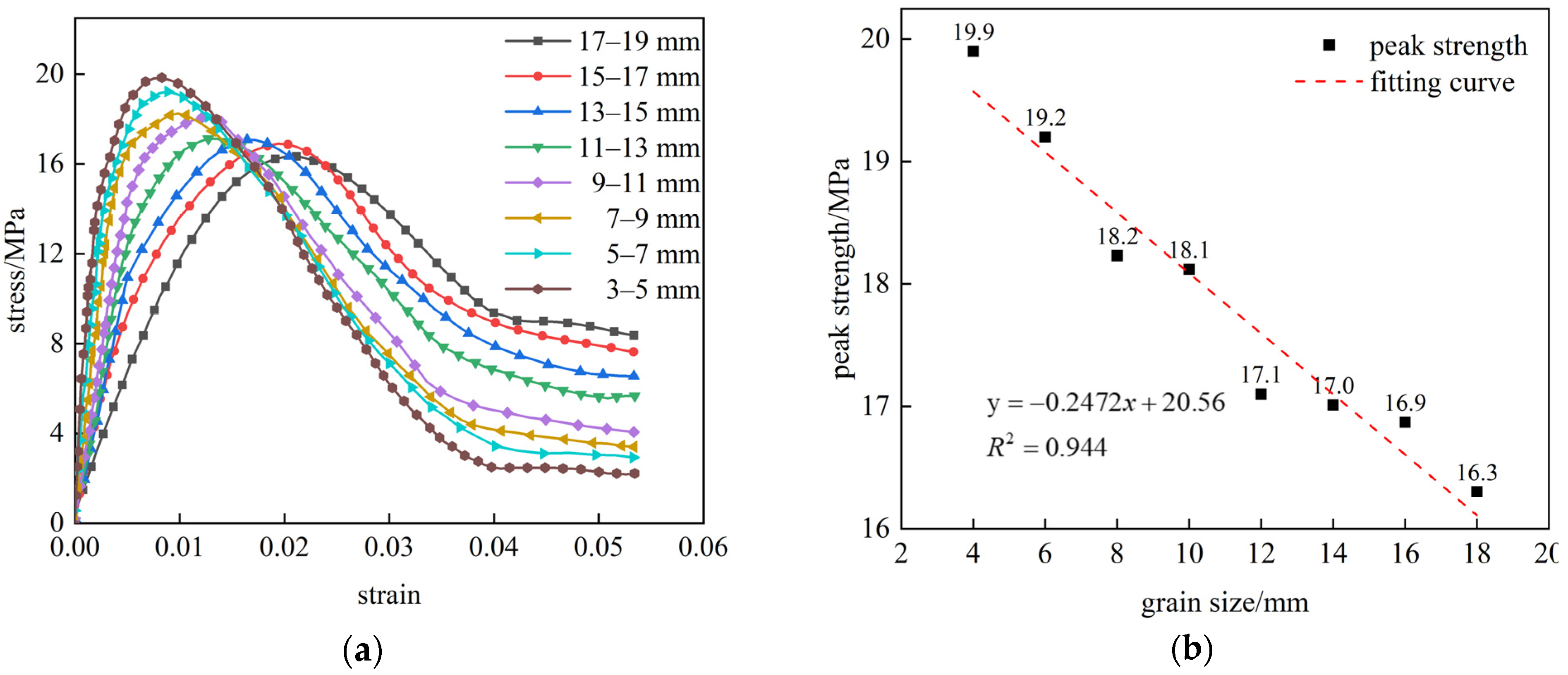
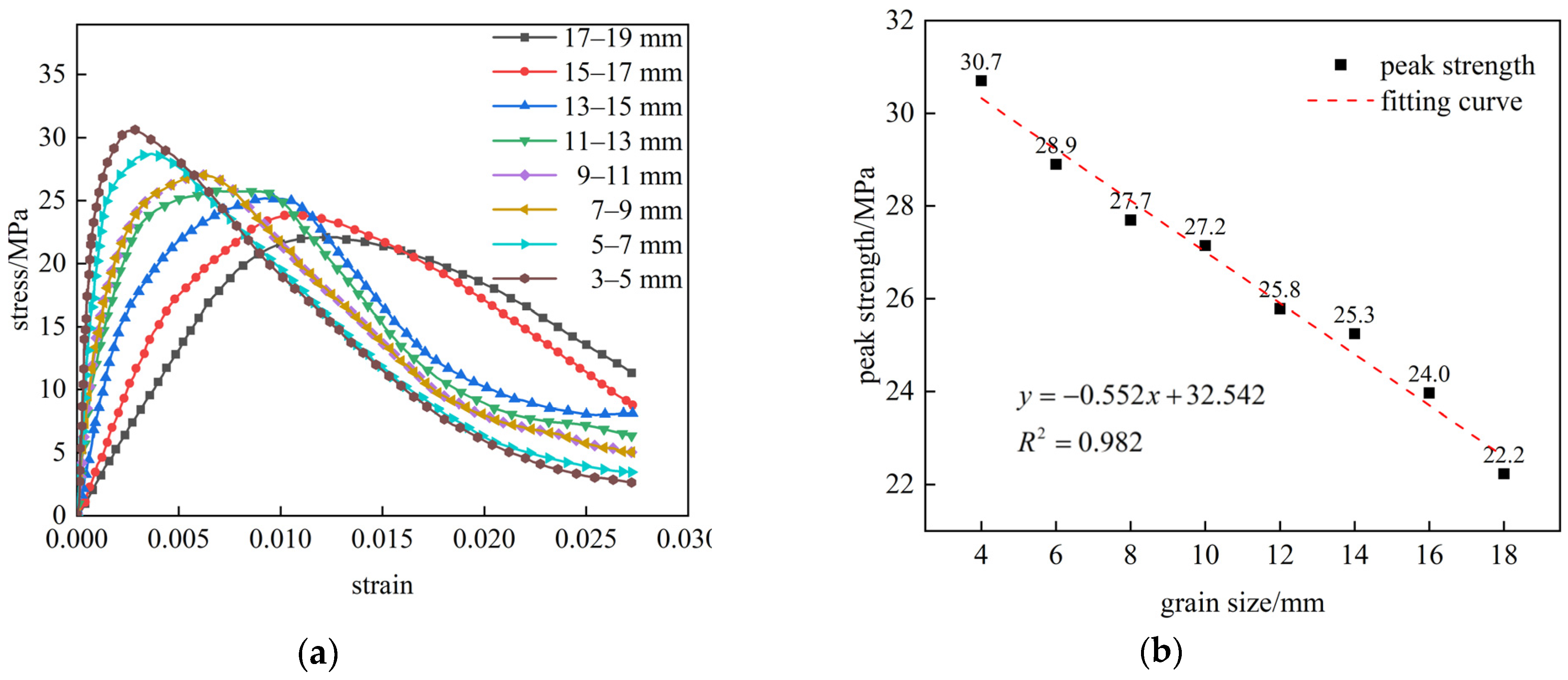
3.1.1. Stress–Strain Curve
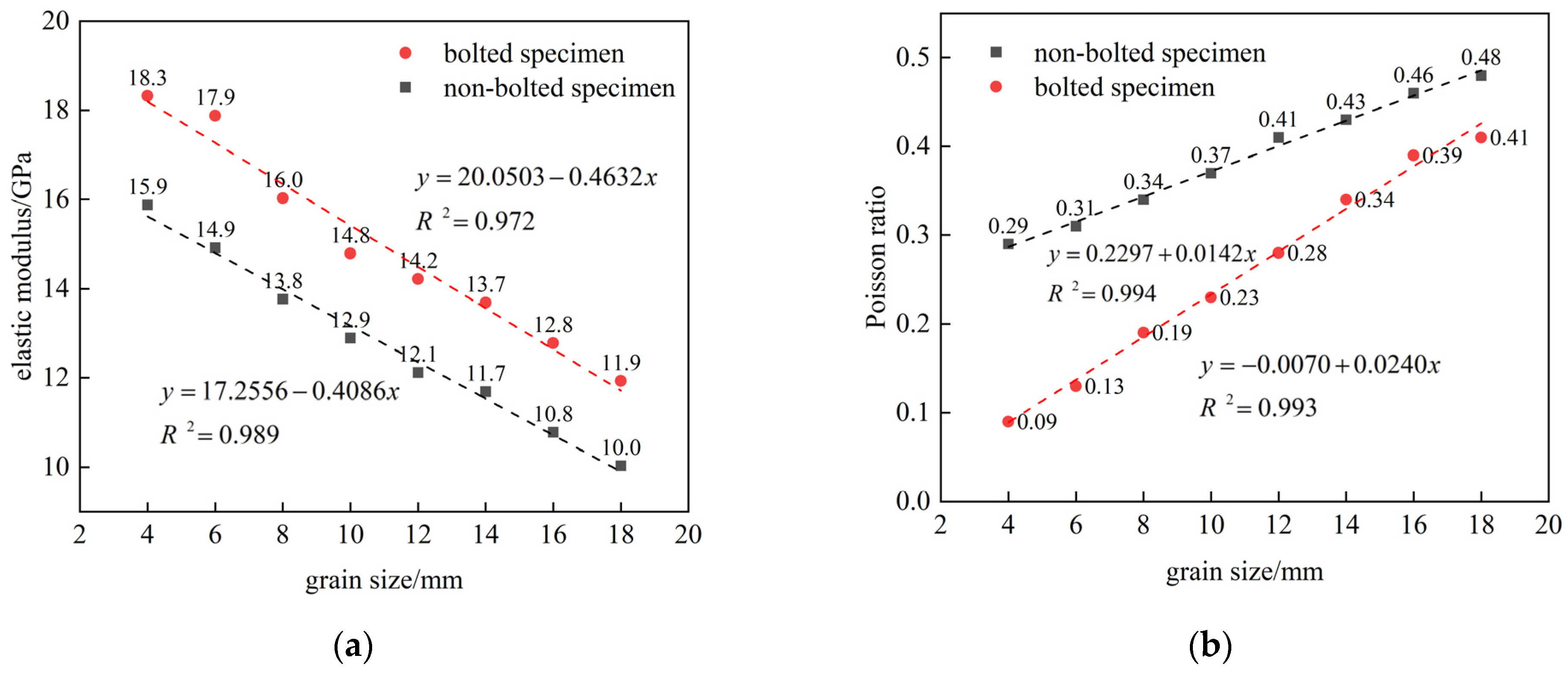
3.1.2. Elastic Modulus and Poisson’s Ratio
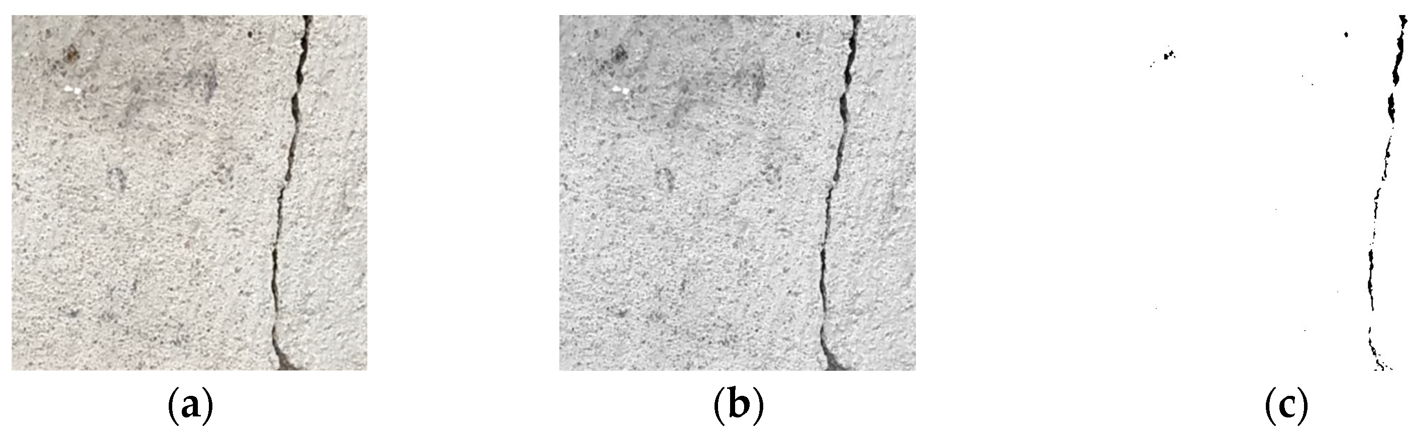
3.2. Analysis of Crack Propagation in Composite Rock Mass
3.2.1. Crack Propagation of Unbolted Composite Rock Mass
3.2.2. Crack Propagation of Bolted Composite Rock Mass
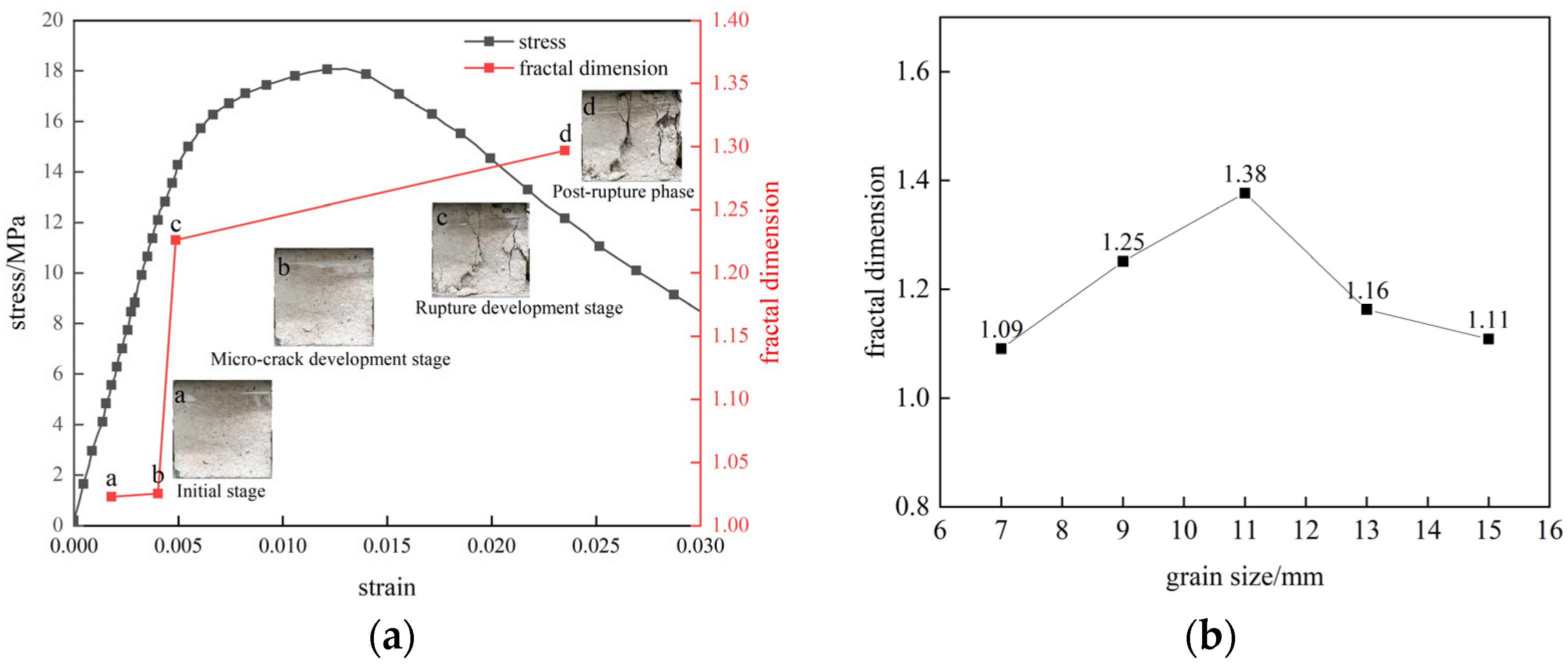
3.2.3. Study on Fractal Characteristics of Combined Rock Mass Fractures
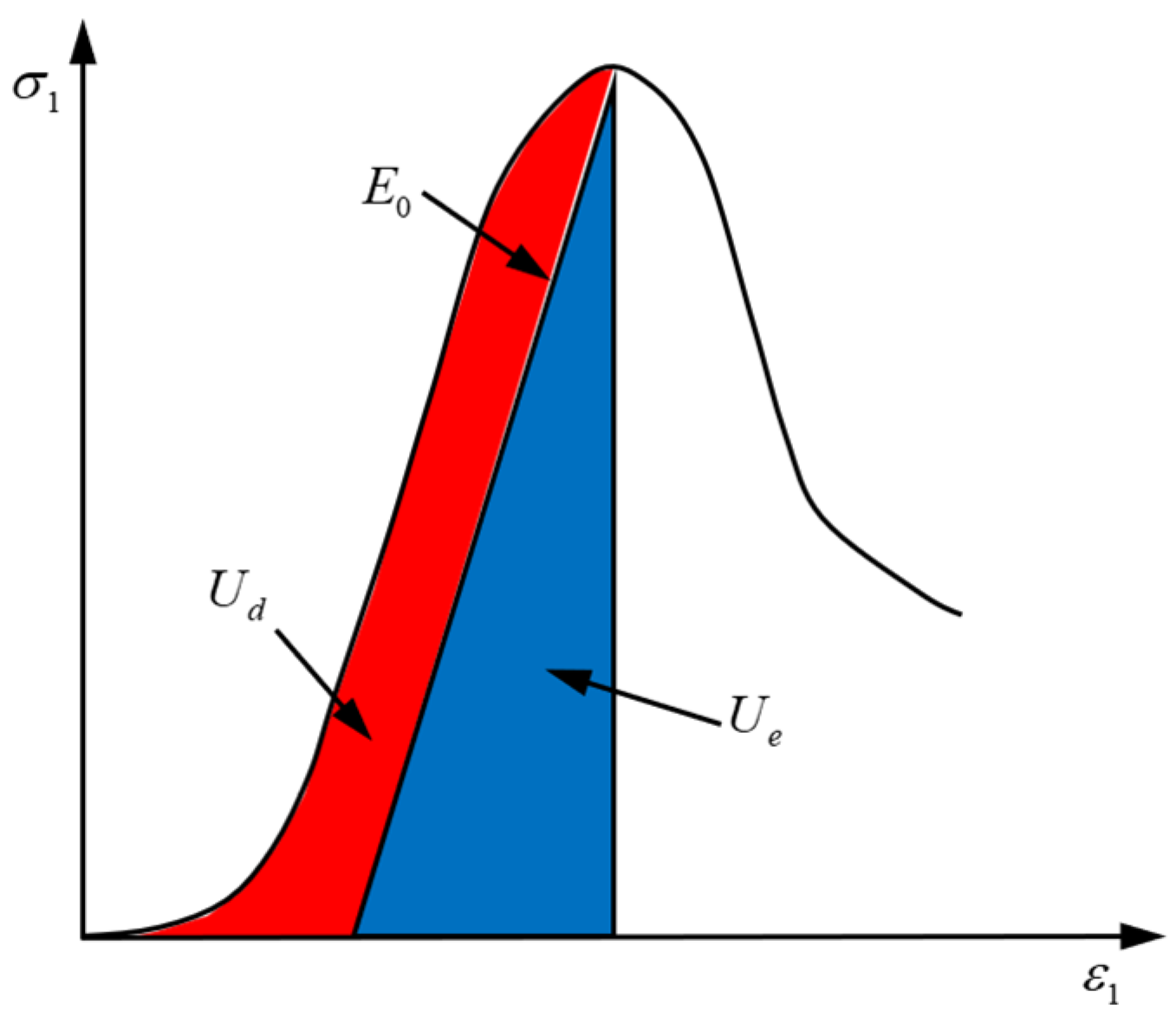
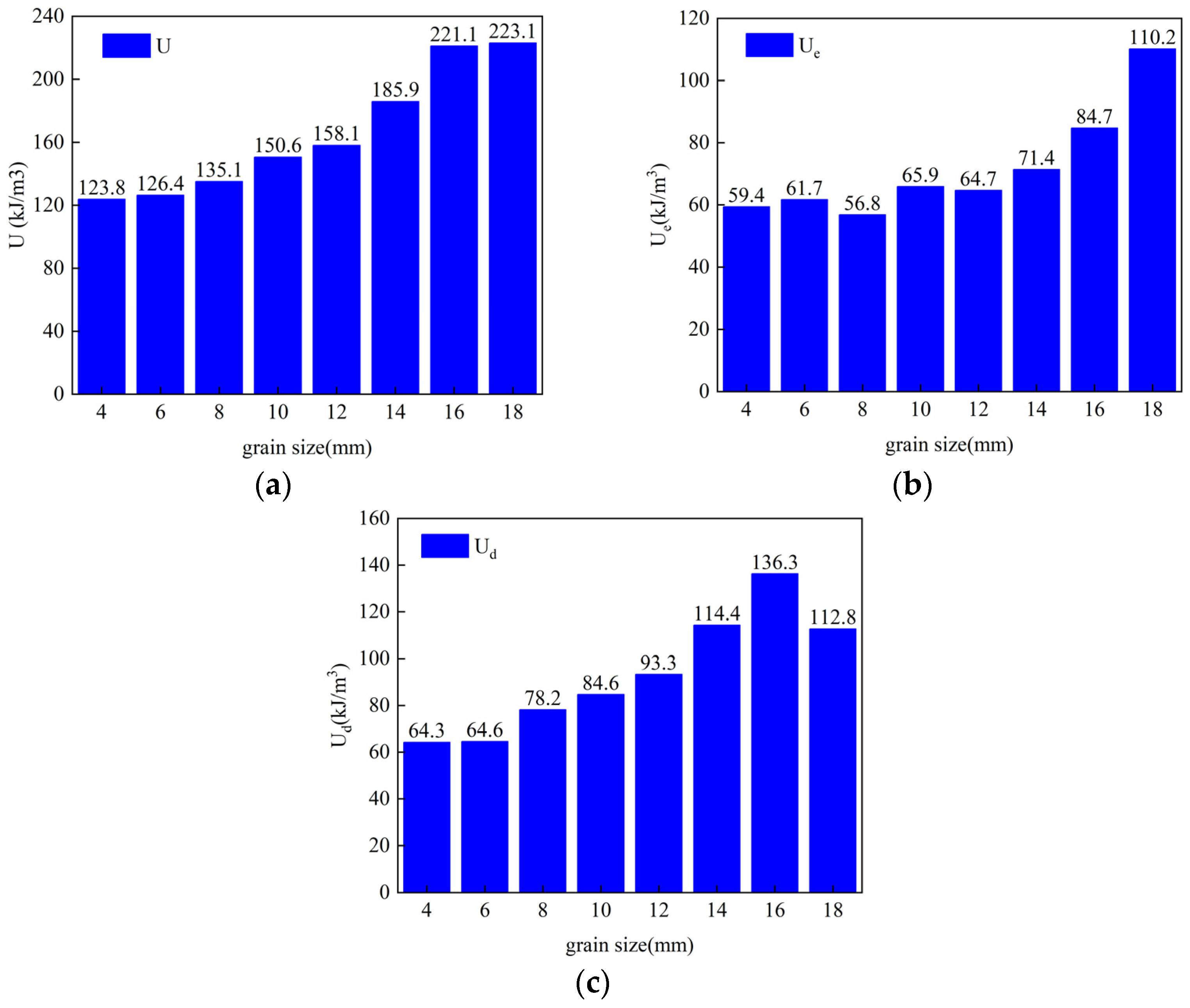
3.3. Energy Evolution of Combined Rock Mass
4. Discussion
- (1)
- For the grouted fractured zones with smaller rock block sizes, the bearing structure exhibits higher strength and greater pressure resistance. However, its post-failure residual strength is low, though still retaining some load-bearing capacity. Reduced friction and interlocking between the small blocks result in weaker overall bearing capacity, consistent with the large-deformation roadway behavior;
- (2)
- Compared to the small grains, the grouted structures with larger rock blocks show lower initial strength and pressure resistance. However, their post-failure residual strength is higher due to enhanced friction and interlocking between the larger blocks, improving the overall bearing capacity;
- (3)
- The prestressed rockbolts significantly enhance the mechanical performance of the bearing structure, suppressing the crack propagation within the anchored zone through weakening, deflection, and arrest effects.
5. Conclusions
- (1)
- Both the non-bolted and bolted composite rock masses exhibited a gradual decrease in the peak strength with increasing grain size, while their post-peak residual strengths progressively increased. The prestressed rock bolts effectively enhanced both the peak and post-peak residual strengths of the composite rock masses. Compared to the bolted specimens, the non-bolted composite rock masses demonstrated a progressively slower decline rate in the post-peak strength stages as the grain size increased, accompanied by more pronounced plastic characteristics;
- (2)
- The elastic modulus of both non-bolted and bolted composite rock masses decreases with increasing grain size, while their Poisson’s ratio increases. Bolted composite rock masses exhibit significantly higher elastic moduli than non-bolted counterparts;
- (3)
- The crack propagation in the composite rock masses evolves through tensile cracks to tensile–shear mixed and shear cracks. With increasing particle size, the shear crack dominance becomes more pronounced. The prestressed bolts exhibit suppressive effects on the crack development within the anchored zones through mechanisms of weakening, deflection, and crack arrest. The variations in the fractal dimension align with the rock crack propagation processes, demonstrating that higher specimen damage levels correspond to greater fractal dimension values;
- (4)
- The total input energy for both the non-bolted and bolted composite rock masses increases with grain size. The bolted specimens demonstrate stronger bearing capacity, higher compressive strength, and reduced energy parameters compared to the non-bolted ones.
Author Contributions
Funding
Data Availability Statement
Conflicts of Interest
References
- Chen, J.; He, H.; Zhang, Y. Dynamic and static analysis of mechanism of loosen zone in surrounding rock of tunnels. Chin. J. Geotech. Eng. 2011, 33, 1964–1968. [Google Scholar]
- Cheng, X.; Li, S.; Gong, X. Experimental study on damage and failure characteristics of similar materials with prefabricated fracture sandstone. Coal Sci. Technol. 2022, 50, 171–178. [Google Scholar] [CrossRef]
- Xu, Y.; Luan, Z.; Xu, X.; Wang, L.; Cui, L.; Miao, C.; Sun, X. Numerical simulation study on tensile-compressive mechanical characteristics of deep pre-cracked anchored soft rock. J. Min. Saf. Eng. 2024, 41, 1134–1147. [Google Scholar] [CrossRef]
- Chen, G.; Tang, W.; Li, T.; Wang, C.; Wang, E.; Zhang, G. Mechanical response and instability model of fractured coal-rock combined body. Rock. Soil. Mech. 2024, 45, 2633–2652. [Google Scholar] [CrossRef]
- Zhang, B.; Liang, Q.; Baotang, S.; Meng, F.; Zhang, W. Experimental study on fracture propagation law of precast rock mass of combined rock mass. Chin. J. Rock. Mech. Eng. 2024, 43, 3690–3699. [Google Scholar] [CrossRef]
- Dinç Göğüş, Ö.; Avşar, E.; Develi, K.; Çalık, A. Quantifying the Rock Damage Intensity Controlled by Mineral Compositions: Insights from Fractal Analyses. Fractal Fract. 2023, 7, 383. [Google Scholar] [CrossRef]
- Wang, L.; Ni, P.; Xie, W.; Wang, S.; Kou, K.; Zhao, K. Microscopic-macroscopic crack evolution mechanism of yellow sandstone with different particle sizes. Rock. Soil. Mech. 2022, 43, 373–381. [Google Scholar] [CrossRef]
- Wu, X.; Wang, F.; Xi, X.; Guo, Q.; Sun, J.; Wang, X. Experimental investigation on the strength characteristics and fracture mechanism of rock with orthogonally crossed cracks. J. China Coal Soc. 2020, 45, 2681–2690. [Google Scholar] [CrossRef]
- Li, Y.; Pan, Y.; Li, Z. Analysis of mechanism of zonal disintegration of rocks. Chin. J. Geotech. Eng. 2006, 1124–1128. [Google Scholar] [CrossRef]
- Li, Y.; Zhang, D.; Song, Y.; Fang, Q.; Chen, F. Experimental research of progressive damage of surrounding rock for soft fractured deep tunnel. Chin. J. Rock. Mech. Eng. 2012, 31, 1138–1147. [Google Scholar]
- Elices, M.; Rocco, C.G. Effect of Aggregate Size on the Fracture and Mechanical Properties of a Simple Concrete. Eng. Fract. Mech. 2008, 75, 3839–3851. [Google Scholar] [CrossRef]
- Cheng, A.; Shu, P.; Zhang, Y.; Wang, P.; Wang, M. Acoustic emission characteristics and damage constitution of backfill-surrounding rock combination. J. Min. Saf. Eng. 2020, 37, 1238–1245. [Google Scholar] [CrossRef]
- Jing, H.; Yin, Q.; Zhu, D.; Sun, Y.; Wang, B. Experimental study on the whole process of instability and failure of anchorage structure in surrounding rock of deep-buried roadway. J. China Coal Soc. 2020, 45, 889–901. [Google Scholar] [CrossRef]
- Su, C.; Gu, M.; Tang, X.; Guo, W. Experiment Study of Compaction Characteristics of Crushed Stones from Coal Seam Roof. Chin. J. Rock. Mech. Eng. 2012, 31, 18–26. [Google Scholar]
- Zhou, H.; Xu, R.; Zhang, C.; Shen, Z.; Meng, F.; Liu, H. Experimental study of crack prevention effect of pre-stressed bolt anchoring. Chin. J. Rock. Mech. Eng. 2015, 34, 2027–2037. [Google Scholar] [CrossRef]
- Yang, P.; Miao, S.; Li, K.; Shang, X.; Li, P.; Cai, M. The Fractal Dimension, Structure Characteristics, and Damage Effects of Multi-Scale Cracks on Sandstone under Triaxial Compression. Fractal Fract. 2025, 9, 51. [Google Scholar] [CrossRef]
- Lei, S.; Hao, D.; Cao, S. Study on Uniaxial Compression Deformation and Fracture Development Characteristics of Weak Interlayer Coal–Rock Combination. Fractal Fract. 2023, 7, 731. [Google Scholar] [CrossRef]
- Pan, C.; Liu, C.; Zhao, G.; Yuan, W.; Wang, X.; Meng, X. Fractal Characteristics and Energy Evolution Analysis of Rocks under True Triaxial Unloading Conditions. Fractal Fract. 2024, 8, 387. [Google Scholar] [CrossRef]
- Zhang, W.; Yu, J.; Ren, J.; Li, C.; Ma, J. Experimental Study on the Butterfly Shape of the Plastic Zone around a Hole near Rock Failure. Fractal Fract. 2024, 8, 215. [Google Scholar] [CrossRef]
- Tang, L.; Tu, S.; Tu, H.; Miao, K.; Li, W.; Zhao, H.; Ma, J.; Zhang, L. Compressive Failure Characteristics of a Coal–Rock Combination at Different Angles: Experimental Study and Fractal Analysis. Fractal Fract. 2024, 8, 240. [Google Scholar] [CrossRef]
- Feng, G.; Liu, C.-B.; Wang, J.-L.; Tao, Y.; Duan, Z.-P.; Xiang, W.-N. Experimental Study on the Fracture Toughness of Granite Affected by Coupled Mechanical-Thermo. Lithosphere 2022, 2022, 5715093. [Google Scholar] [CrossRef]
- Lyu, Q.; Wang, K.; Hu, C.; Dick, J.M.; Shi, J.; Tan, J. Experimental Study on the Mechanical Properties of Shale after Long-Term of Immersion in Fracturing Fluids with Different pH. Rock. Mech. Rock. Eng. 2022, 55, 5047–5061. [Google Scholar] [CrossRef]
- Xie, H.; Gao, F.; Zhou, H.; Zuo, J. Fractal Fracture and Fragmentation in Rocks. J. Disaster Prev. Mitig. Eng. 2003, 1–9. [Google Scholar] [CrossRef]
- Huang, D.; Huang, R.; Zhang, Y. Experimental Investigations On Static Loading Rate Effects On Mechanical Properties And Energy Mechanism Of Coarse Crystal Grain Marble Under Uniaxial Compression. Chin. J. Rock. Mech. Eng. 2012, 31, 245–255. [Google Scholar]


| Number | (a) Initial Cracks | (b) Peak Stress Stage | (c) End of Loading | (d) Side Failure of Specimen |
|---|---|---|---|---|
| SJ-01 |  |  | 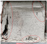 | 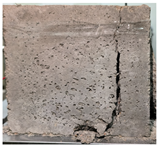 |
| SJ-02 |  |  | 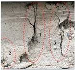 | 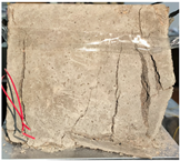 |
| SJ-03 | 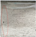 | 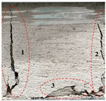 | 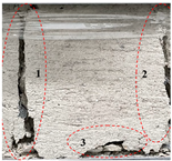 | 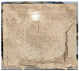 |
| SJ-04 | 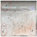 | 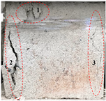 | 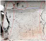 | 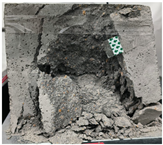 |
| SJ-05 | 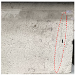 |  |  |  |
| Number | (a) Initial Cracks | (b) Peak Stress Stage | (c) End of Loading | (d) Side Failure of Specimen |
|---|---|---|---|---|
| LJ-01 |  |  |  |  |
| LJ-02 |  | 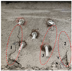 | 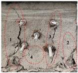 |  |
| LJ-03 | 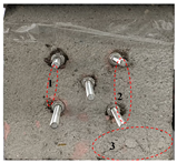 | 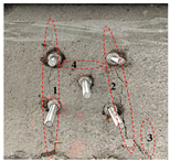 | 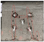 |  |
| LJ-04 | 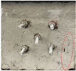 |  |  | 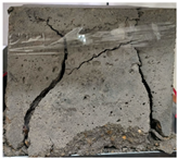 |
| LJ-05 |  | 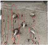 |  |  |
Disclaimer/Publisher’s Note: The statements, opinions and data contained in all publications are solely those of the individual author(s) and contributor(s) and not of MDPI and/or the editor(s). MDPI and/or the editor(s) disclaim responsibility for any injury to people or property resulting from any ideas, methods, instructions or products referred to in the content. |
© 2025 by the authors. Licensee MDPI, Basel, Switzerland. This article is an open access article distributed under the terms and conditions of the Creative Commons Attribution (CC BY) license (https://creativecommons.org/licenses/by/4.0/).
Share and Cite
Yuan, C.; Huang, X.; Wan, W.; Xu, Y. A Study on the Mechanical Properties of Unbolted and Bolted Composite Rock Masses Under the Influence of Different Grain Sizes. Fractal Fract. 2025, 9, 232. https://doi.org/10.3390/fractalfract9040232
Yuan C, Huang X, Wan W, Xu Y. A Study on the Mechanical Properties of Unbolted and Bolted Composite Rock Masses Under the Influence of Different Grain Sizes. Fractal and Fractional. 2025; 9(4):232. https://doi.org/10.3390/fractalfract9040232
Chicago/Turabian StyleYuan, Chao, Xuanqi Huang, Weijun Wan, and Yueyang Xu. 2025. "A Study on the Mechanical Properties of Unbolted and Bolted Composite Rock Masses Under the Influence of Different Grain Sizes" Fractal and Fractional 9, no. 4: 232. https://doi.org/10.3390/fractalfract9040232
APA StyleYuan, C., Huang, X., Wan, W., & Xu, Y. (2025). A Study on the Mechanical Properties of Unbolted and Bolted Composite Rock Masses Under the Influence of Different Grain Sizes. Fractal and Fractional, 9(4), 232. https://doi.org/10.3390/fractalfract9040232